

Page 1
02
satellite navigator
467020
Software rel. 3.0X
installation
Page 2

•
= Generic danger
= Warning
LEGEND SYMBOLS
This manual is an integral part of the equipment to which it refers and must accompany the equipment in
case of sale or change of ownership. Keep it for future reference; ARAG reserves the right to modify the
specications and instructions regarding the product at any time and without prior notice.
Page 3

Contents
•
Legend symbols...............................................................................................................2
1 Product description .........................................................................................................4
1.1 Intended use ............................................................................................................4
2 Precautions ......................................................................................................................4
3 Contents of the package .................................................................................................4
4 Installation ........................................................................................................................ 5
4.1 Introduction ..............................................................................................................5
4.2 System configuration ...............................................................................................5
4.3 General precautions for locating the SKIPPER LT and cable runs ..........................6
4.4 Overall dimensions ..................................................................................................7
4.5 SKIPPER LT navigator position ...............................................................................7
4.6 Locating the antenna ...............................................................................................8
4.7 Electrical connections - general diagram ............................................................... 10
4.8 Connection to the GPS antenna ............................................................................ 10
4.9 Treatment status signal .......................................................................................... 11
4.10 Connection to the power source ............................................................................ 11
5 Maintenance / diagnostics / repairs .............................................................................12
5.1 Troubleshooting .....................................................................................................12
6 Technical data ...............................................................................................................12
7 Disposal at the end of service ...................................................................................... 12
8 Use of the enclosed CD-ROM (Appendix) ...................................................................13
9 Guarantee terms.............................................................................................................14
3
Page 4
1 Product descriPtion
SKIPPER LT is a satellite navigation system that can be used for agricultural spraying and navigation
applications, once connected to the external GPS antenna.
1.1 Intended use
This device is designed to work on agricultural machinery for crop spraying
applications.
The machine is designed and built in compliance with EN ISO 14982 standard
(Electromagnetic compatibility - Forestry and farming machines), harmonized with
2004/108/EC Directive.
SKIPPER LT is not a road navigator and should only be used for eld mapping.
2 Precautions
• Do not expose the device to jets of water.
• Do not use solvents or benzene for cleaning the exterior of the housing.
• Do not use direct jets of water for cleaning the device.
• Make sure the power voltage meets the device’s rated power requirement (12 Vdc).
• If doing arc-welding, disconnect the three connectors from the back of the SKIPPER
LT device and disconnect its power cable.
• Only use original ARAG accessories and spare parts.
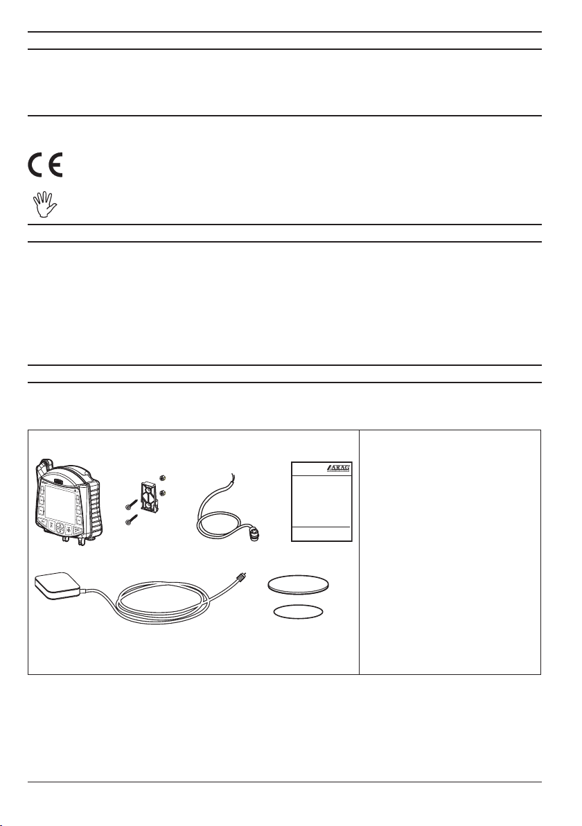
3 contents of the Package
The following table lists the components contained in the SKIPPER LT GPS guidance system
package:
Fig. 1
1
2
3
5 6
4
4
UTILISATIONETENTRETIEN
BEDIENUNGUND WARTUNG
USOEMANUTENZIONE
OWNER’SMANUAL
USOYMANTENIMIENTO
USOEMANUTENÇÃO
1 SKIPPER LT satellite navigator
SKIPPER
2 Mounting bracket kit
3 Power supply cable
4 Instruction manual and CD-ROM
5 GPS Antenna
6 Antenna base
7 Both sides adhesive tape for
antenna base
7
Legend:
Page 5
4 installation
4.1 Introduction
Installation of the SKIPPER LT system does not require specialist knowledge.
We recommend however that this be done by a qualied technician in as much as the installation
also requires electrical connections to be made.
ARAG IS NOT LIABLE FOR ANY DAMAGE CONSEQUENT ON INSTALLATION BY
UNQUALIFIED PERSONS.
IF CASE OF DAMAGE TO THE SYSTEM CAUSED BY INCORRECT INSTALLATION OR
CONNECTIONS, THE WARRANTY IS AUTOMATICALLY VOIDED.
CAUTION! DO NOT CONNECT ANY ANTENNA DIFFERING FROM THE RECOMMENDED ONE (art. no. 520110.600).
ARAG WILL BE HELD HARMLESS FROM ANY LIABILITY IN CASE OF PRODUCT
DAMAGES, FAULTS AND RISKS OF ANY KIND CAUSED BY THE CONNECTION OF
THE MODULE WITH NON-ORIGINAL ANTENNAS OR ANTENNAS NOT SUPPLIED BY
ARAG.
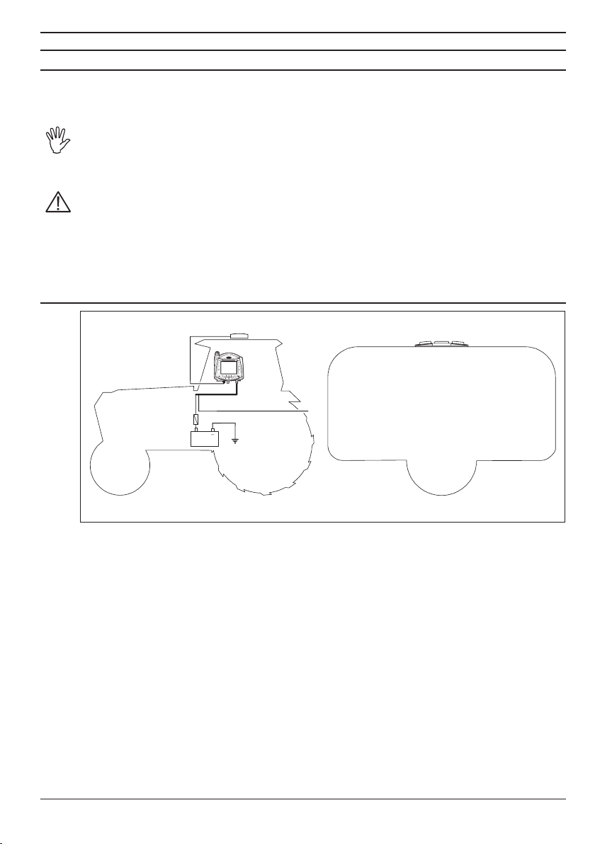
4.2 System conguration
B
Fi g. 2
C
+
12 Vdc
A
Legend:
a SKIPPER LT satellite navigator
B GPS antenna
c Battery
D
d Treatment status signal +12 Vdc
(from main control valve)
5
Page 6

4.3 General precautions for locating the SKIPPER LT and cable runs
Positioning the SKIPPER LT device in the cab:
- DO NOT place the navigator in areas subject to excessive vibrations and shocks or
close to moving parts which might cause damages;
- Mount the remote control unit in a visible position, without obstructing the opera-
tor’s view, and within easy reach by hand;
- Take care to position the device away from moving parts to avoid accidental operation of its keys.
Inserting the connectors:
- Fit supplied O-rings into connectors and then connect paying special attention to
the notch. Press gently and then tighten the ring nut.
CAUTION: do not use tools to tighten down the connector locking collars.
- Do not force the connectors by pushing too hard or bending them: the contacts
can be damaged and monitor operation compromised.
Securing the cables:
- Note the various connections required for the SKIPPER LT system to operate, the
necessary length of the cables, and ensure that there is sufficient space for the cable
runs and connectors:
- Route the cables in such a way that twisting and machine movements cannot damage or break them;
- Route the cables in such a way that they cannot come into contact with moving
parts;
- If, due to limited space, the cabling has to run around a corner, make sure that the
bend is not too sharp as this may cause the cable to break.
Use ONLY the cables and accessories listed in the catalogue; these have the correct
specications for their intended application.
6
Page 7

4.4 Overall dimensions
161.6
65.3
2
2
1
162.0
1 USB HOST port (pendrive, etc...)
2 GPS Antenna
3 Power supply
Fig. 3
4.5 SKIPPER LT navigator position
Carefully read all instructions as described in par. 4.3 - General precautions for correct SKIPPER LT and cable positioning before positioning the satellite navigator.
Position SKIPPER LT centrally into the cab so that it does not impair driving visibility while allowing
data check during treatment.
1
2
1) Install the mount slide in the cab with
the provided bolts, in a location which
is within easy reach and visible to the
operator, and away from moving parts.
2) Fit the satellite navigator by pushing
it onto the mount slide and pushing
down until it locks in place.
Legend:
3
Fi g. 4
7
Page 8

4.6 Locating the antenna
The user must position the GPS antenna as indicated in this manual.
Installing the antenna:
Installation of the antenna on agricultural equipment must observe certain basic requirements:
• it must be installed on the highest point of the machine (including trailer): the skywards reception
angle must be as unobstructed as possible.
Fig. 5
Fig. 6
The antenna must be installed on the lengthwise axis of the machine.
Fig. 7 Fig. 8
8
Page 9

Antenna fastening:
The antenna has a magnetic base and should be positioned on a at metal surface (e.g. farm machine roof). In case of plastic roof, use the supplied metal plate and sticker.
Remove one of the protective lms from the sticker and stick it onto the metal plate. Then remove
the other protective lm and position the plate where the antenna is being tted after cleaning the
whole area.
It is important that the metal plate and the antenna are positioned onto a at surface
free from any objects which might reduce adhesive adherence.
metal plate
sticker
Fig. 9
Check for proper metal plate xing at regular intervals so to avoid its accidental
detachment.
9
Page 10

4.7 Electrical connections - general diagram
A
B
WIRE COLOR
(POWER CABLE)
black negative
red positive
green treatment status signal
6m
RESPECTIVE
CONNECTION
E
3A
D
+
C
Fi g. 10
a Satellite navigator
B GPS Antenna
c Battery
d Automotive fuse - 3 A
e Treatment status signal +12 Vdc (from main control valve)
4.8 Connection to the GPS antenna
Only use the specic ARAG GPS antenna to be used in connection with SKIPPER LT.
ARAG shall not be held liable for loss or damage due to use of different types of
antenna.
Before making the connection, carefully read par. 4.3 - General precautions for locating the SKIPPER LT and cable runs.
Connect the external GPS antenna to Skipper LT.
The connection points are given in par. 4.7 - Electrical connections - general diagram.
10
Page 11

4.9 Treatment status signal
If the machine is equipped with a treatment control, such as a switch on the control valve, the
SKIPPER LT can be connected to a corresponding treatment status signal, so that it receives a
+12 Vdc signal directly from the control itself when treatment starts.
We recommend that the control be connected to the main control valve positive pole.
Since the current in question is very low, the cable connection to the control need not be of any
special cross-section.
CAUTION: the connection to the treatment control must be done by a qualied technician.
ARAG is not liable for damage to the system, persons, animals or things due to
incorrect connection of the above control or modications to the system, cabling,
connectors or any other components required to make the connection.
• If the treatment start control connection is not made, the operational status of the equipment must
be entered into the SKIPPER LT manually with the key USER.
4.10 Connection to the power source
CAUTION!
To avoid short circuits, do not connect the power cable connector before the installation is completed.
Before powering up the guidance monitor and remote control unit, make sure the
engine battery voltage rating is correct (12 Vdc).
SKIPPER LT is powered directly by the vehicle battery (12 Vdc): SKIPPER LT should ALWAYS be
switched on from the satellite navigator, whereas it should be switched off by means of the appropriate button on the control panel.
The vehicle battery may go at if SKIPPER LT stays on for a long time when the engine is not running: in case of long stops - with engine OFF - disconnect SKIPPER LT
from the battery (rif. Fig. 10).
CAUTION:
• The power circuit must ALWAYS be tted with a 3 Amp automotive fuse.
• All battery connections must be made with cables with a minimum cross section
of 1 mm
2
.
• Use cables with suitable terminals to ensure correct connection of each individual
wire.
11
Page 12

5 Maintenance / diagnostics / rePairs
- Clean only with a soft wet cloth.
- DO NOT use detergents or aggressive products.
- DO NOT aim water jets directly at the navigator.
5.1 Troubleshooting
ProBleM cause solution
The display does not switch on No power supply • Check power supply connection.
No signal enabling treatment to
SKIPPER LT
Display shows message
The GPS receiver doesn't give
valid data
Display shows message
Differential correction not
available
Tab. 1
Power cable improperly
connected
Improper set-up • Check set-up (par. 4.7).
Wrong GPS antenna cable connection
Satellite connection in progress • Wait for connection to be established.
DGPS signal not available in the
work area
DGPS connection in progress • Wait for connection to be established.
• Check green lead connection to power
cable (par. 4.7).
• Check connection with GPS antenna
(par. 4.7).
• Disable DGPS.
6 technical data
Description SKIPPER LT
Display LCD 4", 65000 colors, 420 cd/m
Power supply 9 - 15 Vdc
Working temperature
Storage temperature
Weight 550 g
1 USB 1.1 port HOST
Treatment input Active high (+12 Vdc)
Tab. 2
0 °C ÷ 45 °C
+32 °F ÷ +113 °F
-20 °C ÷ 60 °C
-4 °F ÷ +140 °F
2
7 disPosal at the end of service
Dispose of the system in compliance with the established legislation in the country of use.
12
Page 13

8 use of the enclosed cd-roM (aPPendiX)
The product you purchased comes with a CD-ROM containing the manuals for installation, use and
maintenance in all available languages at the time of purchase.
The CD-ROM is compatible with all Microsoft® WindowsTM systems and, if autorun function is enabled,
it is loaded automatically upon insertion.
*
Press on the button corresponding to the language of the manual you wish to view (Adobe® Reader
must be already installed on the PC).
If Adobe® Reader®, is not installed on your PC, you can install it** by pressing “Install” and following
on-screen instructions.
If the CD-ROM does not run automatically:
Using My Computer, open the CD-ROM and double click on the autorun le.
*
For Mac® users:
You can directly open the manuals from the CD-ROM by clicking on the corresponding PDF le icon.
*
®
Pictures are indicative and can vary
*
according to the product used.
Adobe Reader is an Adobe Systems Incorporated trademark.
**The CD-ROM includes the English version 8.1 of the Adobe® Reader® software.
Other versions and/or languages can be downloaded from www.adobe.com.
13
Windows is a Microsoft Corporation trademark.
Mac is a registered name of Apple Incorporated.
Page 14

9 guarantee terMs
1. ARAG s.r.l. guarantees this apparatus for a period of 360 day (1 year) from the date of sale
to the client user (date of the goods delivery note). The components of the apparatus, that
in the unappealable opinion of ARAG are faulty due to an original defect in the material or
production process, will be repaired or replaced free of charge at the nearest Assistance
Centre operating at the moment the request for intervention is made.
The following costs are excluded:
- disassembly and reassembly of the apparatus from the original system;
- transport of the apparatus to the Assistance Centre.
2. The following are not covered by the guarantee:
- damage caused by transport (scratches, dints and similar);
- damage due to incorrect installation or to faults originating from insufficient or inadequate
characteristics of the electrical system, or to alterations resulting from environmental, climatic or other conditions;
- damage due to the use of unsuitable chemical products, for spraying, watering, weedkilling or any other crop treatment, that may damage the apparatus;
- malfunctioning caused by negligence, mishandling, lack of know how, repairs or modications carried out by unauthorised personnel;
- incorrect installation and regulation;
- damage or malfunction caused by the lack of ordinary maintenance, such as cleaning of
lters, nozzles, etc.;
- anything that can be considered to be normal wear and tear.
3. Repairing the apparatus will be carried out within time limits compatible with the organisational needs of the Assistance Centre.
No guarantee conditions will be recognised for those units or components that have not
been previously washed and cleaned to remove residue of the products used.
4. Repairs carried out under guarantee are guaranteed for one year (360 days) from the
replacement or repair date.
5. ARAG will not recognise any further expressed or intended guarantees, apart from those
listed here.
No representative or retailer is authorised to take on any other responsibility relative to
ARAG products.
The period of the guarantees recognised by law, including the commercial guarantees and
allowances for special purposes are limited, in length of time, to the validities given here. In
no case will ARAG recognise loss of prots, either direct, indirect, special or subsequent to
any damage.
6. The parts replaced under guarantee remain the property of ARAG.
7. All safety information present in the sales documents regarding limits in use, performance
and product characteristics must be transferred to the end user as a responsibility of the
purchaser.
8. Any controversy must be presented to the Reggio Emilia Law Court.
14
Page 15

Conformity Declaration
ARAG s.r.l.
Via Palladio, 5/A
42048 Rubiera (RE) - Italy
P.IVA 01801480359
Dichiara
che il prodotto
descrizione: Navigatore satellitare
modello: Skipper LT
codice: 467020
risponde ai requisiti di conformità contemplati nelle seguente Direttiva Europea:
2004/108/CE e successive modificazioni
(Compatibilità Elettromagnetica)
Riferimenti alle Norme Applicate:
EN ISO 14982:2001
(Macchine agricole e forestali - Compatibilità elettromagnetica
Metodi di prova e criteri di accettazione)
Rubiera, 09 Febbraio 2009
Giovanni Montorsi
(Presidente)
Page 16

Only use original ARAG accessories and spare parts, to maintain safety conditions foreseen by the constructor.
Always refer to the ARAG spare parts catalogue.
42048 RUBIERA (Reggio Emilia) - ITALY
Via Palladio, 5/A
Tel. 0522 622011
Fax 0522 628944
http://www.aragnet.com
info@aragnet.com
D20202_GB-m03 04/2013
 Loading...