


SERIE 4663

ELECTRIC CONTROL BOX
7 - 9 WAY
46635763B
46635963B
INSTALLATION, USE AND MAINTENANCE

• LEGEND SYMBOLS
= Generic danger
= Warning
This manual is an integral part of the equipment to which it refers and must accompany the equipment in
case of sale or change of ownership. Keep it for future reference; ARAG reserves the right to modify the
specifications and instructions regarding the product at any time and without prior notice.

INDEX
• Legend symbols .............................................................................................................................. 2
• Foreword and guide to the manual .............................................................................................. 4
• Using the manual ............................................................................................................................ 4
• Restrictions ...................................................................................................................................... 4
• Responsibilities ...............................................................................................................................4
1 Risks and precautions before assembly .................................................................................... 5
2 Intended use ..................................................................................................................................... 5
3 Contents of the package ................................................................................................................ 5
4 Location on the machine ............................................................................................................... 6
4.1 Location of the control box .................................................................................................... 6
4.1.1 Location advice and precautions ...................................................................................... 6
4.1.2 Mounting the bracket .......................................................................................................... 6
4.2 Overall dimensions ................................................................................................................ 7
4.3 Recommended system configuration ................................................................................... 7
5 Location of the control unit on the agricultural machine ........................................................ 8
6 Routing the cables .......................................................................................................................... 8
6.1 Routing recommendations .................................................................................................... 8
6.2 Connections ........................................................................................................................... 8
6.2.1 Cable markings ................................................................................................................... 8
6.2.2 Fitting the connectors to the control box .......................................................................... 9
6.2.3 Connecting SICMA connector ........................................................................................... 9
6.2.4 Connection of control unit connectors .............................................................................. 9
6.2.5 Sensor connections .......................................................................................................... 10
6.2.6 Power connection ............................................................................................................. 10
6.2.7 Operating modes .............................................................................................................. 11
6.2.8 Setting “M” or “P” operation mode ................................................................................ 11
7 Computer control and display .................................................................................................... 12
7.1 Control panel ........................................................................................................................ 12
7.2 Using the switches ............................................................................................................... 12
8 Digital display - pressure display .............................................................................................. 13
8.1 Notes on programming ........................................................................................................ 13
8.2 Setting before use ................................................................................................................ 13
8.2.1 “OPT” advanced menu .................................................................................................... 13
8.2.2 “UNIT” unit of measure ..................................................................................................... 13
8.3 Programming ........................................................................................................................ 14
8.3.1 Setting the full scale .......................................................................................................... 14
8.4 Use ........................................................................................................................................ 14
8.4.1 Displaying data .................................................................................................................. 14
8.4.2 Adjusting the value of 0 .................................................................................................... 14
9 Using the control box ................................................................................................................... 15
9.1 Adjustment of the control unit ............................................................................................. 15
10 Maintenance / diagnostics / repairs ........................................................................................... 16
10.1 Precautions .......................................................................................................................... 16
10.2 Troubleshooting ................................................................................................................... 16
10.3 Defective operating .............................................................................................................. 16
11 Control box - specifications ........................................................................................................ 17
12 End of life disposal ....................................................................................................................... 17
13 Accessories .................................................................................................................................... 17
14 Guarantee terms ............................................................................................................................ 18
3

• FOREWORD AND GUIDE TO THE MANUAL
This manual contains the information needed to assemble and connect the series 4663 control
boxes.
All other information is provided on special sheets, to be used only by the installer, which include
speci c data for each single model.
• USING THE MANUAL
This manual contains information reserved for the installation technician, and hence makes use
of technical terminology without the explanations which would otherwise be required by the end
user.
INSTALLATION IS TO BE DONE ONLY BY AUTHORISED AND TRAINED TECHNICAL
STAFF. THE MANUFACTURER IS NOT LIABLE FOR USE OF THIS MANUAL BY UNAUTHORIZED AND UNQUALIFIED PERSONS.
• RESTRICTIONS
Assembly steps are described with reference to a “generic” control box and therefore no speci c
models will be referenced unless a speci c installation operation involves a single model.
• RESPONSIBILITIES
The installation technician is responsible for implementing the installation procedure in a professional
manner so as to guarantee perfect functionality of the computer, whether supplied solely with
ARAG components or with components from other manufacturers.
ARAG recommends using its own components for the installation of the control systems.
If the installation technician should decide to use components provided by other manufacturers,
even if this should not require the modi cation of the cabling or other systems, he does so at his
own exclusive risk and liability.
The installation technician is responsible for compatibility with components and accessories provided by other manufacturers.
If, as a consequence of the above recommendations, the computer or other ARAG components
installed in combination with components provided by other manufacturers should suffer damage
of any kind, no form of liability, whether direct or indirect, will be recognized by ARAG.
4
1 RISKS AND PRECAUTIONS BEFORE ASSEMBLY
All installation work must be done with the battery disconnected, using suitable
tools and any individual protection equipment deemed necessary.
Use ONLY clean water for treatment tests and simulations: using chemicals
during simulated treatment runs can seriously injure persons in the vicinity.
2 INTENDED USE
The control box is a device which, when connected to a valve or suitable control unit, makes it
possible to control all phases of treatment in agricultural applications directly from the cab of the
agricultural machine in which it is installed.
This device is designed to work on agricultural machinery for crop spraying applications.
The unit is designed and constructed to comply with directive 89/336/EEC
of 03/05/1989 and all its subsequent modi cations, and to EN ISO 14982
(Electromagnetic compatibility - agricultural and forestry equipment).
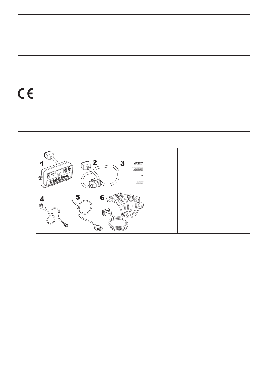
3 CONTENTS OF THE PACKAGE
The following table lists the components contained in the control box package:
Fig. 1
1 Control box
Legend:
2 Extension cable
3 Instructions
4 Digital display cable
5 Power cable
6 Terminal cable for valve
connection
5

4 LOCATION ON THE MACHINE
4.1 Location of the control box
4.1.1 Location advice and precautions
• Control boxes are intended to be located on the machine in the control cab, in a visible and easyto-reach position so as to allow the operator to control the spray area during operation without
blocking his view.
• Note the various connections required for the device to operate, the necessary length of the cables,
and ensure that there is suf cient space for the cable runs and connectors.
• Do not locate the control box near to moving parts or in areas subject to harsh
vibrations or collisions to avoid damaging the box or activating the switches
involuntarily.
4.1.2 Mounting the bracket
The control box must be mounted on a bracket installed at the desired location, using the latter as
a drilling template (Fig. 2).
The bracket can be removed by undoing the knobs (take care not to lose the nuts and washers)
and installed with M8 bolts (not supplied).
If the bracket has been removed, mount it securely in position, install the box to it and lock down
the mounting knobs.
Do not use any system other than the provided bracket for mounting the control box.
6
 Loading...