


digi


CELL POWERED VERSION
4628405
4628506
4628707
Software rel. 1.0X
INSTALLATION, USE AND MAINTENANCE

LEGEND SYMBOLS
 = Generic danger
 = Warning
This manual is an integral part of the equipment to which it refers and must accompany the equipment in case of sale or change of ownership. Keep it for future reference; ARAG reserves the right to modify the specifications and instructions regarding the product at any time and without prior notice.

|
|
|
CONTENTS |
1 |
Product description........................................................................................................................................................... |
4 |
|
|
1.1 |
Intended use............................................................................................................................................................... |
4 |
2 |
Flowmeter assembly.......................................................................................................................................................... |
4 |
|
|
2.1 |
Monitor rotation........................................................................................................................................................... |
5 |
|
2.2 |
Dimensions (mm)........................................................................................................................................................ |
6 |
|
2.3 |
Hydraulic connections................................................................................................................................................. |
6 |
|
2.3.1 Hydraulic connection for brass/fork connections....................................................................................................... |
6 |
|
|
2.4 |
Power supply............................................................................................................................................................... |
7 |
|
2.4.1 Battery replacement................................................................................................................................................... |
7 |
|
3 |
Controls in the menu......................................................................................................................................................... |
8 |
|
|
Menu structure................................................................................................................................................................... |
9 |
|
4 |
Preliminary setup for use................................................................................................................................................ |
10 |
|
|
4.1 |
Calibration................................................................................................................................................................. |
10 |
|
4.1.1 |
Automatic calibration................................................................................................................................................. |
10 |
|
4.1.2 |
Manual calibration..................................................................................................................................................... |
11 |
|
4.2 |
Flowrate alarms........................................................................................................................................................ |
12 |
|
4.3 |
Display...................................................................................................................................................................... |
12 |
|
4.4 |
Energy saving........................................................................................................................................................... |
13 |
|
4.5 |
Options..................................................................................................................................................................... |
13 |
|
4.5.1 |
Language.................................................................................................................................................................. |
13 |
|
4.5.2 Units of measurement............................................................................................................................................... |
14 |
|
|
4.5.2.1 Rate units of measurement.................................................................................................................................... |
14 |
|
|
4.5.2.2 Volume units of measurement................................................................................................................................ |
14 |
|
|
4.6 |
Test........................................................................................................................................................................... |
15 |
|
4.6.1 |
Display test............................................................................................................................................................... |
15 |
|
4.6.2 Keys test................................................................................................................................................................... |
15 |
|
5 |
Use |
............................................................................................................................................................................... |
16 |
|
5.1 |
Partial totalizer reset................................................................................................................................................. |
16 |
6 |
Cleaning and repair.......................................................................................................................................................... |
17 |
|
|
6.1 |
Troubleshooting......................................................................................................................................................... |
17 |
|
6.2 |
Paddle cleaning and replacement............................................................................................................................. |
18 |
|
6.3 |
OR replacement........................................................................................................................................................ |
19 |
7 |
Technical data ................................................................................................................................................................. |
20 |
|
8 |
Disposal at the end of service ....................................................................................................................................... |
20 |
|
9 |
Guarantee terms............................................................................................................................................................... |
22 |
|
3
INTRODUCTION
1 PRODUCT DESCRIPTION
DigiWolf is a battery powered paddle flowmeter capable of measuring the rate of a fluid in a hydraulic circuit, and it can display the results of these measurements.
1.1Intended use
This device is designed to work on agricultural machinery for crop spraying applications.
The machine is designed and built in compliance with EN ISO 14982 standard (Electromagnetic compatibility - Forestry and farming machines), harmonized with 2004/108/EC Directive.
The flowmeter must not be used to measure the passage of hydrocarbons, flammable, explosive or toxic liquids. The flowmeter is not suitable for contact with liquids for human consumption.
2 Flowmeter ASSEMBLY
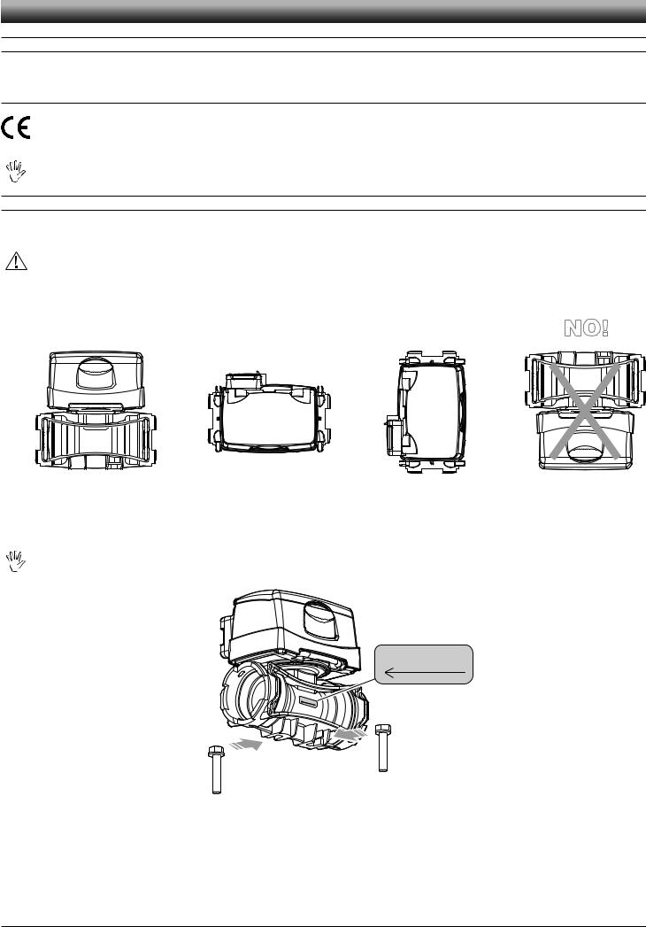
Install the flowmeter at least 20 cm from the elements that could cause turbulence inside the tubes (valves, bends, constrictions, etc.). The flowmeter can be installed in a vertical or horizontal position.
CAUTION:
-Do not install the flowmeter with the connector facing downwards (Fig. 1).
-The system must have a filtering element with a filter of at least 50 mesh, together with a safety valve to limit use pressure at the specified max. valve (Tab. 2 - Par. 2.3.1).
OK |
OK |
OK |
NO! |
Fig. 1
Assemble the flowmeter using the suitable mounting parts (Fig. 2): fit the bolts (M8) in their seats, then make them slide to their stop position to prevent them from coming out.
The flowmeter body must be assembled with the arrow on the label facing the flow direction.
APPROXIMATE CONSTANT
XXX
APPROXIMATE |
CONSTANT |
|
|
XXX |
|
Fig. 2
4

INSTALLATION
2.1Monitor rotation
In case of vertical assembly, to simplify the use of the DigiWolf it is possible to rotate the monitor by 90° with respect to the body (Fig. 3).
Fig. 3
1) Remove the fork from the monitor using a screwdriver. 2) Remove the monitor from the flowmeter body.
Fig. 4
If the monitor is turned upside down, the letters A and B can be seen: these correspond to the two possible monitor positions (parallel and perpendicular to the body).
DigiWolf is supplied with the sensor in position A (parallel to the body).
Fig. 5
With the aid of a screwdriver, loosen the screw locking the sensor without removing it.
Fig. 6
Rotate the sensor anti-clockwise until reaching B stop position.
Tighten back the screw without forcing it. The monitor is ready to be fitted in perpendicular position to the body.
Fit the monitor back on the flowmeter body.
Fig. 7
5
INSTALLATION
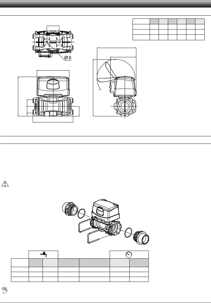
2.2Dimensions (mm)
E |
CODE |
A |
B |
C |
D |
E |
T |
|
4628405 |
140 |
128 |
205 |
31 |
41 |
T5 |
|
4628506 |
145 |
148 |
210 |
36 |
45 |
T6 |
|
4628707 |
157 |
162 |
222 |
41 |
45 |
T7 |
|
143 |
|
|
|
|
|
Tab. 1 |
95
120
C
A
T
D
Fig. 8
B
2.3Hydraulic connections
2.3.1Hydraulic connection for brass/fork connections
Avoid bends and constrictions before connections and on tubes.
Use ARAG connections with their suitable OR with MALE CONNECTIONS [T connections - General Catalogue (Tab. 2)].
The tubes must be able to stand a pressure of at least twice the max. operation pressure of the flowmeter (Tab. 2) CONSIDERING THE OPERATION PRESSURES WITHIN THE SYSTEM.
Hose tail tightening must be done using the suitable metal clamps to ensure perfect mechanical sealing, even at high pressures. The connection with threaded connectors must be done paying attention to operation pressure.
CAUTION: For the implementation on already operating systems it is necessary to follow all safety rules described herein. System assembly and start-up must be carried out by expert personnel according to the safety rules so as to ensure the same safety level of the system the flowmeter is going to be installed in.
After connection, check for the perfect sealing of the tubes and fork connections.
|
|
|
|
|
|
|
|
Fig. 9 |
CODE |
l/min. |
US GPM |
Connection |
Ø equivalent (inch) |
Max. p |
Max. p |
|
|
(bar) |
(PSI) |
|
||||||
|
|
|
|
|
|
|
||
4628405 |
10-200 |
2.6-53 |
T5 F |
1 |
1/4" |
20 |
290 |
|
4628506 |
20-400 |
5-106 |
T6 F |
1 |
1/2" |
12 |
174 |
|
4628707 |
40-800 |
10-210 |
T7 F |
|
2" |
7 |
130 |
Tab. 2 |
|
|
|
|
|
|
|
|
|
The diameter in inches (Ø equivalent) is given only as an indication of the typical passage of the flowmeter body. Actually, it is possible to choose different sizes depending on the fork connection used.
6
INSTALLATION
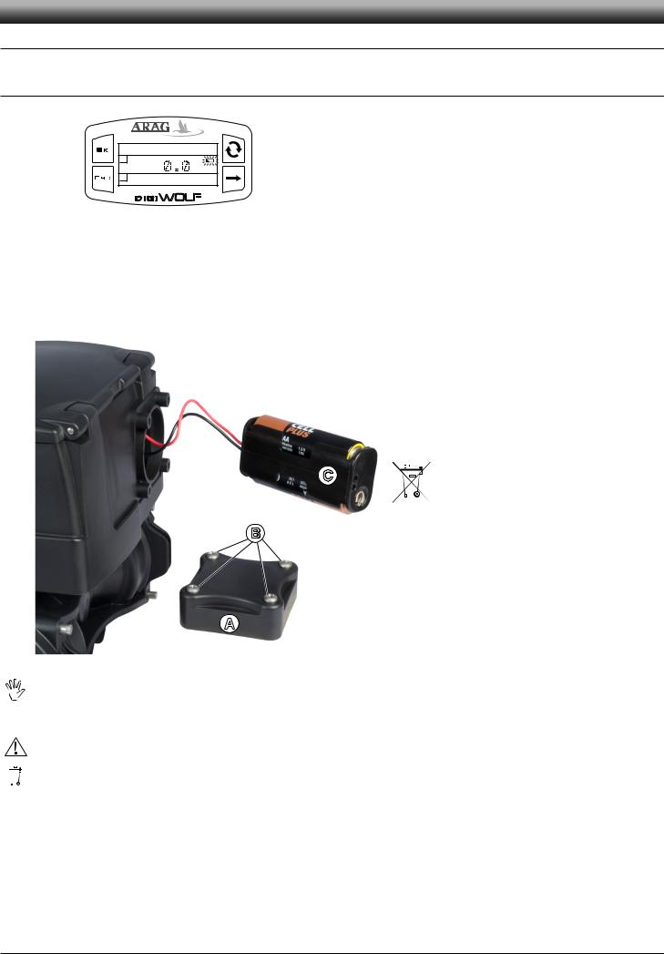
2.4Power supply
DigiWolf is powered by 2 AA batteries type LR6 (alkaline) or FR6 (Li-Fe S2).
2.4.1Battery replacement
0.0 l/min
1
2 |
0.0 l |
|
When the batteries are low, the symbol  will blink on the display.
Fig. 10
To insert or replace the batteries, proceed as follows:
1)Remove the lid of the battery compartment (A) loosening the 4 screws (B);
2)Remove the battery support (C) and replace the batteries, respecting their polarity (as indicated).
3)Fit the support back in its housing and refit the lid by tightening the 4 screws without forcing them, taking care not to crush or break the wires in the battery case and that the lid seal remains in its seat.
C
B
Fig. 11
A
To avoid damaging the device, replace low batteries as soon as this symbol is displayed  . Remember to remove the batteries when the device is not going to be in use for a long period.
Use only the recommended type of batteries. Do not use combinations of different types of batteries (old and new, carbon and alkaline, etc.). Do not try to recharge the batteries.
ARAG is not liable for damage to the equipment, persons, animals or things caused by failure to observe the above instructions.
Do not dispose of exhausted batteries in the environment. Dispose of in a suitable container.
7
SETUP
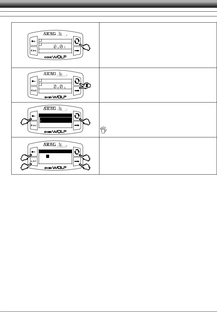
3 CONTROLS IN THE MENU
|
|
|
|
SWITCH ON |
|
|
|
|
The display turns on automatically at liquid passage. If you need to switch on the |
|
1 |
0.0 l |
|
device to check or modify data, press OK. |
|
|
|
DigiWolf switches on and displays the figure shown. |
|
|
2 |
|
|
|
|
|
0.0 l/min |
Press the key to see the succession of different values written in full (central part |
|
|
|
of the display). |
||
|
|
|
|
|
|
|
|
|
At first device switch on, or after battery replacement, the device will briefly |
Fig. 12 |
|
|
|
display its name and software version. |
|
|
|
|
|
|
1 |
0.0 l |
|
ACCESS TO SETUP MENU |
|
2 |
|
|
|
|
|
0.0 l/min |
Press the keys for 2 seconds at the same time to access setup menu. |
|
|
|
|
||
Fig. 13 |
|
|
|
|
|
|
|
|
SELECTION AND ACCESS TO MENU ITEMS |
|
Setup menu |
|
A Press in succession to move through items (the selected item is highlighted with |
|
|
Calibration |
|
|
|
|
|
|
a black band) |
|
B |
Display |
|
A |
|
|
|
|
B Press to access the selected item |
|
|
Flowrate alarms |
|
|
|
|
|
|
|
Three dots under an item show the presence of another setup menu. |
Fig. 14 |
|
|
|
|
|
|
|
|
MODIFYING DATA |
|
Flowrate constant |
A Press to toggle from one digit to another |
||
|
|
|
|
|
C |
00123 |
B |
B Press in succession to modify the value of the digit highlighted by the cursor |
|
|
|
|||
|
Min value |
|
1 |
C Press to confirm the change. The display goes back to the previous screen. |
|
Max value |
50000 |
||
D |
|
|
A |
D Press to exit current page without confirming changes. |
Fig. 15 |
|
|
|
|
8
 Loading...