


02
300S Bravo series computer MULTI-ROW SPRAYER
•DIRECT CONNECTION: 46731xXX
•RCU: 46733XXX
Software rel. 3.xx
installaTion

•Legend symbols
 = Generic danger
 = Warning
This manual is an integral part of the equipment to which it refers and must accompany the equipment in case of sale or change of ownership. Keep it for future reference; ARAG reserves the right to modify the specifications and instructions regarding the product at any time and without prior notice.

|
|
Contents |
|
• |
Legend symbols............................................................................................................... |
2 |
|
• |
Manual foreword and use................................................................................................ |
4 |
|
• |
Manual use modes........................................................................................................... |
4 |
|
• |
Limitations........................................................................................................................ |
4 |
|
• |
Responsibility................................................................................................................... |
4 |
|
1 |
Risks and protections before assembly......................................................................... |
4 |
|
2 |
Bravo DSB......................................................................................................................... |
4 |
|
3 |
Intended use..................................................................................................................... |
5 |
|
4 |
Precautions....................................................................................................................... |
5 |
|
5 |
Package content............................................................................................................... |
6 |
|
6 |
Position on farming machine.......................................................................................... |
7 |
|
|
6.1 |
System recommended composition......................................................................... |
7 |
|
6.2 |
Monitor and control unit positioning........................................................................ |
10 |
|
6.3 |
Bracket fixing.......................................................................................................... |
11 |
|
6.4 |
Control unit (RCU) fixing........................................................................................ |
11 |
|
6.5 |
Control unit position................................................................................................ |
12 |
|
6.6 |
Hydraulic unit positioning....................................................................................... |
12 |
7 |
Computer connection to the farming machine............................................................ |
12 |
|
|
7.1 |
General precautions for a correct harness position................................................ |
12 |
|
7.2 |
Power supply connection........................................................................................ |
13 |
8 |
Harness connection to the control unit, the hydraulic unit and the |
. |
|
|
available functions......................................................................................................... |
14 |
|
|
8.1 |
Multicore connector connection (only for versions with direct connection)............. |
14 |
|
8.2 |
Remote control unit (RCU) connection................................................................... |
14 |
|
8.3 |
Control unit valve connection................................................................................. |
14 |
|
8.4 |
Hydraulic valves connection................................................................................... |
15 |
|
8.5 |
Connection of sensors and other available functions............................................. |
16 |
|
8.6 |
SD memory card.................................................................................................... |
18 |
9 |
Maintenance / Diagnostics / Repairs............................................................................ |
19 |
|
|
9.1 |
Troubleshooting...................................................................................................... |
19 |
|
9.2 |
Computer technical data......................................................................................... |
19 |
10 |
Guarantee terms............................................................................................................. |
22 |
|
11 |
Disposal at the end of service....................................................................................... |
22 |
|
3

•Manual foreword and use
This manual provides instructions to assemble, connect and set the computers of the BRAVO 300S family.
Any other information is provided in specific sheets to be used exclusively by the installer, containing specific information of each computer model.
•Manual use modes
The section of this manual dedicated to the installation contains information for installers. For this reason we have used technical terms without providing explanations which would be necessary for end users only.
THE INSTALLATION MUST BE CARRIED OUT BY AUTHORISED AND SKILLED PERSONNEL ONLY.ARAG IS NOT RESPONSIBLE FOR ANY OPERATION SPECIFIED INTHIS MANUAL CARRIED OUT BY UNAUTHORISED OR UNSKILLED PERSONNEL.
•Limitations
The descriptions of the assembly phases refer to a "general" computer, so specific models will not be mentioned, unless a certain installation procedure concerns exclusively one computer type.
•Responsibility
The installer must carry out workmanlike installations and ensure to the end user the perfect operation of the whole system both with ARAG components only and other brands' components.
ARAG always recommends using its components to install control systems.
The installer will be held responsible for any malfunction if he decides to use other brands' components even without actually changing the system parts or harness.
The compatibility check with components and accessories of other manufacturers shall be carried out by the installer.
If the computer or the ARAG components installed together with other brands' components get damaged because of what stated above, no direct or indirect warranty will be provided.
1Risks and protections before assembly
All installation works must be done with battery disconnected, using suitable tools and any individual protection equipment deemed necessary.
Use ONLY clean water for treatment tests and simulations: using chemicals during simulated treatment runs can seriously injure persons in the vicinity.
2Bravo DSB
ARAG has designed and manufactured a diagnostics system for Bravo series computers and the systems they may be connected to.
BRAVO DSB (code 467003) provides reliable diagnostics of computer, control unit or the whole system to troubleshoot any potential problems experienced with the BRAVO DSB system.
4

3Intended use
Bravo 300S is a computer which, when connected to a valve or suitable control unit, makes it possible to control all phases of treatment in agricultural applications directly from the cabin of the farming machine it is installed in.
This device is designed to work on agricultural machinery for crop spraying applications.
The machine is designed and built in compliance with EN ISO 14982 standard (Electromagnetic compatibility - Forestry and farming machines), harmonized with 2004/108/EC Directive.
4Precautions
•Do not aim water jets at the equipment.
•Do not use solvents or fuel to clean the case outer surface.
•Do not clean equipment with direct water jets.
•Comply with the specified power voltage (12 Vdc).
•In case of voltaic arc welding, remove connectors from BRAVO 300S and disconnect the power cables.
•Only use ARAG genuine spare parts and accessories.
5

5Package content
The table below indicates the components that you will find in the BRAVO 300S computer package:
BRAVO 300S COMPUTER WITH DIRECT CONNECTION
Legend:
1 Bravo 300S
2 Instruction manual
3 Power cable
4 SD memory card
5 Fixing kit
6 Power supply connector
7 Complete harness to connect valves and sensors
8 Inductive speed sensor
9 Section valve connector seals
Fig. 1a
BRAVO 300S COMPUTER WITH RCU
Fig. 1b
1Bravo 300S
2Instruction manual
3Control unit (RCU) with harnesses 3a Connection cable to the hydraulic unit 3b Connection cable to the control unit
3c Connection cable to power supply and sensors
3d Connection cable to monitor
Legend:
4SD memory card
5Fixing kit
6Inductive speed sensor
7a Section valve connector seals
7b Hydraulic valve connector seals
8 Power supply connector
6

6Position on farming machine
6.1System recommended composition
DIRECT CONNECTION
Assembly diagram for multi-row sprayer with diaphragm pump - System with main valve
|
|
Legend: |
* * |
A |
Bravo 300S |
|
B |
Battery |
|
D |
Filling pump |
|
F |
Flowmeter |
|
G |
Main valve |
|
M |
Pressure sensor |
|
P |
Control valve |
|
R |
Foam marker |
|
S |
Speed sensor |
|
T |
Filling flowmeter / Pump |
|
|
Protector / RPM Sensor |
|
X |
Level sensor |
|
1÷5 |
Section valves |
Fig. 2
DIRECT CONNECTION
Assembly diagram for multi-row sprayer with diaphragm pump - System with drain valve
* |
Legend:
ABravo 300S
BBattery
DFilling pump
|
|
|
|
|
|
|
|
|
|
|
|
|
F |
Flowmeter |
|
|
|
|
|
|
|
|
|
|
|
|
|
G |
Drain valve |
|
|
|
|
|
|
|
|
|
|
|
|
|
||
|
|
|
|
|
|
|
|
|
|
|
|
|
M |
Drain valve |
|
|
|
|
|
|
|
|
|
|
|
|
|
P |
Control valve |
|
|
|
|
|
|
|
||||||||
|
|
|
|
|
|
|
||||||||
|
|
|
|
|
|
|
||||||||
|
|
|
|
|
|
|
|
|
|
|
|
|
||
|
|
|
|
|
|
|
|
|
|
|
|
|
R |
Foam marker |
SSpeed sensor
TFilling flowmeter / Pump Protector / RPM Sensor
X Level sensor 1÷5 Section valves
Fig. 3
The computer must be directly connected to the farming machine battery. * Do not connect the computer to key-operated switch (15/54).
7
DIRECT CONNECTION
Assembly diagram for multi-row sprayer with centrifugal pump
* |
|
Legend: |
|
A |
Bravo 300S |
||
|
|||
|
B |
Battery |
|
|
D |
Filling pump |
|
|
F |
Flowmeter |
|
|
M |
Pressure sensor |
|
|
P |
Control valve |
|
|
R |
Foam marker |
|
|
S |
Speed sensor |
|
|
T |
Filling flowmeter / |
|
|
|
RPM Sensor |
|
|
X |
Level sensor |
|
|
1÷5 |
Section valves |
Fig. 4
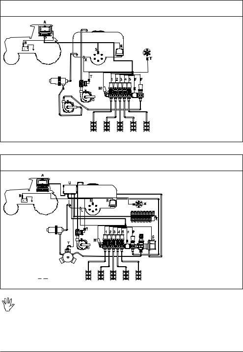
RCU
Assembly diagram for multi-row sprayer with diaphragm pump - System with main valve
* |
Fig. 5
Legend:
ABravo 300S
BBattery
D Filling pump
EHydraulic unit
F |
Flowmeter |
G |
Main valve |
L |
Level sensor |
M |
Pressure sensor |
P |
Control valve |
R |
Foam marker |
SSpeed sensor
TFilling flowmeter / Pump Protector
URCU
X RPM sensor 1÷5 Section valves
The computer must be directly connected to the farming machine battery. * Do not connect the computer to key-operated switch (15/54).
8
 Loading...