

Page 1

ELECTRIC CONTROL BOX
7 - 9 WAY
46635763B
46635963B
INSTALLATION, USE AND MAINTENANCE
Page 2

• LEGEND SYMBOLS
= Generic danger
= Warning
This manual is an integral part of the equipment to which it refers and must accompany the equipment in
case of sale or change of ownership. Keep it for future reference; ARAG reserves the right to modify the
specifications and instructions regarding the product at any time and without prior notice.
Page 3

INDEX
• Legend symbols .............................................................................................................................. 2
• Foreword and guide to the manual .............................................................................................. 4
• Using the manual ............................................................................................................................ 4
• Restrictions ...................................................................................................................................... 4
• Responsibilities ...............................................................................................................................4
1 Risks and precautions before assembly .................................................................................... 5
2 Intended use ..................................................................................................................................... 5
3 Contents of the package ................................................................................................................ 5
4 Location on the machine ............................................................................................................... 6
4.1 Location of the control box .................................................................................................... 6
4.1.1 Location advice and precautions ...................................................................................... 6
4.1.2 Mounting the bracket .......................................................................................................... 6
4.2 Overall dimensions ................................................................................................................ 7
4.3 Recommended system configuration ................................................................................... 7
5 Location of the control unit on the agricultural machine ........................................................ 8
6 Routing the cables .......................................................................................................................... 8
6.1 Routing recommendations .................................................................................................... 8
6.2 Connections ........................................................................................................................... 8
6.2.1 Cable markings ................................................................................................................... 8
6.2.2 Fitting the connectors to the control box .......................................................................... 9
6.2.3 Connecting SICMA connector ........................................................................................... 9
6.2.4 Connection of control unit connectors .............................................................................. 9
6.2.5 Sensor connections .......................................................................................................... 10
6.2.6 Power connection ............................................................................................................. 10
6.2.7 Operating modes .............................................................................................................. 11
6.2.8 Setting “M” or “P” operation mode ................................................................................ 11
7 Computer control and display .................................................................................................... 12
7.1 Control panel ........................................................................................................................ 12
7.2 Using the switches ............................................................................................................... 12
8 Digital display - pressure display .............................................................................................. 13
8.1 Notes on programming ........................................................................................................ 13
8.2 Setting before use ................................................................................................................ 13
8.2.1 “OPT” advanced menu .................................................................................................... 13
8.2.2 “UNIT” unit of measure ..................................................................................................... 13
8.3 Programming ........................................................................................................................ 14
8.3.1 Setting the full scale .......................................................................................................... 14
8.4 Use ........................................................................................................................................ 14
8.4.1 Displaying data .................................................................................................................. 14
8.4.2 Adjusting the value of 0 .................................................................................................... 14
9 Using the control box ................................................................................................................... 15
9.1 Adjustment of the control unit ............................................................................................. 15
10 Maintenance / diagnostics / repairs ........................................................................................... 16
10.1 Precautions .......................................................................................................................... 16
10.2 Troubleshooting ................................................................................................................... 16
10.3 Defective operating .............................................................................................................. 16
11 Control box - specifications ........................................................................................................ 17
12 End of life disposal ....................................................................................................................... 17
13 Accessories .................................................................................................................................... 17
14 Guarantee terms ............................................................................................................................ 18
3
Page 4

• FOREWORD AND GUIDE TO THE MANUAL
This manual contains the information needed to assemble and connect the series 4663 control
boxes.
All other information is provided on special sheets, to be used only by the installer, which include
speci c data for each single model.
• USING THE MANUAL
This manual contains information reserved for the installation technician, and hence makes use
of technical terminology without the explanations which would otherwise be required by the end
user.
INSTALLATION IS TO BE DONE ONLY BY AUTHORISED AND TRAINED TECHNICAL
STAFF. THE MANUFACTURER IS NOT LIABLE FOR USE OF THIS MANUAL BY UNAUTHORIZED AND UNQUALIFIED PERSONS.
• RESTRICTIONS
Assembly steps are described with reference to a “generic” control box and therefore no speci c
models will be referenced unless a speci c installation operation involves a single model.
• RESPONSIBILITIES
The installation technician is responsible for implementing the installation procedure in a professional
manner so as to guarantee perfect functionality of the computer, whether supplied solely with
ARAG components or with components from other manufacturers.
ARAG recommends using its own components for the installation of the control systems.
If the installation technician should decide to use components provided by other manufacturers,
even if this should not require the modi cation of the cabling or other systems, he does so at his
own exclusive risk and liability.
The installation technician is responsible for compatibility with components and accessories provided by other manufacturers.
If, as a consequence of the above recommendations, the computer or other ARAG components
installed in combination with components provided by other manufacturers should suffer damage
of any kind, no form of liability, whether direct or indirect, will be recognized by ARAG.
4
Page 5
1 RISKS AND PRECAUTIONS BEFORE ASSEMBLY
All installation work must be done with the battery disconnected, using suitable
tools and any individual protection equipment deemed necessary.
Use ONLY clean water for treatment tests and simulations: using chemicals
during simulated treatment runs can seriously injure persons in the vicinity.
2 INTENDED USE
The control box is a device which, when connected to a valve or suitable control unit, makes it
possible to control all phases of treatment in agricultural applications directly from the cab of the
agricultural machine in which it is installed.
This device is designed to work on agricultural machinery for crop spraying applications.
The unit is designed and constructed to comply with directive 89/336/EEC
of 03/05/1989 and all its subsequent modi cations, and to EN ISO 14982
(Electromagnetic compatibility - agricultural and forestry equipment).
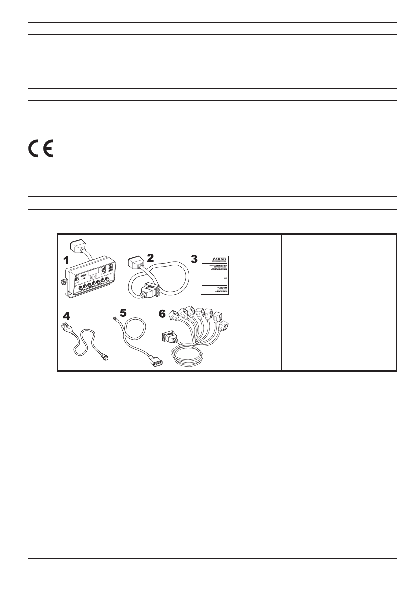
3 CONTENTS OF THE PACKAGE
The following table lists the components contained in the control box package:
Fig. 1
1 Control box
Legend:
2 Extension cable
3 Instructions
4 Digital display cable
5 Power cable
6 Terminal cable for valve
connection
5
Page 6

4 LOCATION ON THE MACHINE
4.1 Location of the control box
4.1.1 Location advice and precautions
• Control boxes are intended to be located on the machine in the control cab, in a visible and easyto-reach position so as to allow the operator to control the spray area during operation without
blocking his view.
• Note the various connections required for the device to operate, the necessary length of the cables,
and ensure that there is suf cient space for the cable runs and connectors.
• Do not locate the control box near to moving parts or in areas subject to harsh
vibrations or collisions to avoid damaging the box or activating the switches
involuntarily.
4.1.2 Mounting the bracket
The control box must be mounted on a bracket installed at the desired location, using the latter as
a drilling template (Fig. 2).
The bracket can be removed by undoing the knobs (take care not to lose the nuts and washers)
and installed with M8 bolts (not supplied).
If the bracket has been removed, mount it securely in position, install the box to it and lock down
the mounting knobs.
Do not use any system other than the provided bracket for mounting the control box.
6
Page 7

4.2 Overall dimensions
Fig. 2
4.3 Recommended system con guration
Assembly diagram for crop sprayers with membrane pump
Tab. 1
Legend:
A Control box
B Terminal cable
D Display connection
E Extension cable
G Main valve
K Starter key
M Pressure sensor
P Proportional valve
Z Extension
1÷9 Section valves
7
Page 8

5 LOCATION OF THE CONTROL UNIT ON THE AGRICULTURAL MACHINE
The control unit must be installed with the special brackets supplied and mounted to the unit, positioning it as shown in the provided manual.
MAKE SURE TO FOLLOW ALL THE SAFETY INSTRUCTIONS GIVEN IN THE
CONTROL UNIT’S MANUAL
6 ROUTING THE CABLES
6.1 Routing recommendations
If, due to limited space, the cabling has to run around a corner, make sure that the bend is
•
not too sharp as this may cause breakage of the cables;
Make sure the cabling cannot come into contact with moving parts;
•
Route the cables in such a way that twisting and machine movements cannot damage or
•
break them;
Take care not to break, pull, tear or cut the cables.
•
Routing the cables to protect against water in ltrations:
The branch of the cables running to the valves must always be DOWNWARDS at the end
(Fig. 3).
Fig. 3
• Use only the cables provided with the ARAG control box.
• Use of unsuitable cables or cables not provided by ARAG automatically voids the
warranty.
• ARAG is not liable for damage to the equipment, persons or animals caused by
failure to observe the above instructions.
6.2 Connections
6.2.1 Cable markings
Tab. 2 gives all the instructions for connecting the cables to the available services.
CABLE MARKING CONNECTION
Extension cable
1-7
Terminal cable for
1-9
valve connection
Power
Tab. 2
Digital display signal cable
CAUTION: ALWAYS use the extension cable.
Without this cable the valves will not function correctly.
8
-
Section valve cables
Section valves
G
P
-
-
Main valve
Valvola proporzionale
12 Vdc power
Sensor wiring harness
Page 9

6.2.2 Fitting the connectors to the control box
1 Control unit connection (SICMA con-
nector for intermediate cable).
2 Digiblock connector (polarised con-
nector with locking collar).
3 Power socket (polarised AMP connec-
tor with locking tab. Press to lock).
Fig. 4
Legend:
Fitting the cables to the connection points: do not force the connectors by pushing
too hard or bending them; the contacts can be damaged and control box operation
compromised.
6.2.3 Connecting SICMA connector
Fig. 5
• Open purple connector slide (1, Fig. 5).
• Position the connector (2) onto its socket (3) and press without forcing.
• Close purple cursor slide (4) until it is fully locked.
If it is hard to be connected, check connector position.
6.2.4 Connection of control unit connectors
Fig. 6
• Remove the protective cap (1 in Fig. 6) from the valve.
• Position the gasket (2) tting it on the connector (3), then connect the connector by pressing it
down completely (4): be careful not to bend the electrical contacts on the valve while
inserting it.
• Screw in the screw (5) until thoroughly tightened.
9
Page 10

6.2.5 Sensor connections
Fasten connectors according to the abbreviations indicated in the main assembly diagram
(par. 4.3).
The cables are marked to indicate the service to which they connect.
Table 1 gives full indications for the connections.
The sensor connection instructions are provided with the respective products.
Connect the ow meter or transducer connector with the correct polarity; insert in the correct way
and push in until the tab clicks.
Fig. 7
Use ONLY the accessories listed in the catalogue; these have the correct
speci cations for their intended application.
6.2.6 Power connection
CAUTION: Before powering up the control box and control unit, make sure the battery voltage is as speci ed (12 Vdc).
Power up the control box with the starter key, using the provided power cable
(component 5 - Tab. 1).
If the 15/54 contact (services) of the start key can bear a continuous load of 10A, install the
•
connections indicated in Fig. 8, with a 10A fuse on the power cable.
•
Otherwise install a relay as indicated in Fig. 9, and install a 10 A fuse on the power cable.
•
Use cables whose section is a minimum of 2.5 mm2.
Direct connection
Fig. 8
Fig. 9
Connection via relay
CAUTION:
• To avoid short circuits, do not connect the power cable before the installation is
completed.
• Use cables with suitable terminals to ensure correct connection of each individual
wire.
10
Page 11

6.2.7 Operating modes
Control boxes can operate in “M” or “P” mode, depending on power cable connection (par.
6.2.8).
• “M” mode of operation:
Section valves are closed or opened from the main switch provided that section valve switches
are set in the appropriate position; in other words, if section switches are set to OFF (lever down),
operating the main switch does not affect the sections. If one or more section valve switches are set
to ON (lever up), opening or closing the main switch opens or closes the section valves as well.
• “P” mode of operation:
section valves are operated independently.
Main switch control functions do not affect section valve opening or closing.
6.2.8 Setting “M” or “P” operation mode
The power cable has an additional wire for operating mode setting (par. 6.2.7).
Operation mode depends on the type of connection:
Fig. 10
Fig. 11
11
Page 12

7 COMPUTER CONTROL AND DISPLAY
7.1 Control panel
Fig. 12
7.2 Using the switches
Control box ON/OFF switch
• Move the switch up (led on) to power the control box on.
• Move the switch down (led off) to power the control box off.
WARNING: If the control box is left on, it may drain the battery.
Control valve switch
• to open the control valve, move the switch up (led on).
• to close the control valve, move the switch down (led off).
Section valve switches
• To open the section valve, move the corresponding switch up (led on).
• To close the section valve, move the corresponding switch down (led off).
The section valve control depend on the type of operation enabled with the computer: for full details,
refer to Par. 6.2.7 - Operating modes.
Proportional control valve switch
The lever is normally in the center.
• to increase the amount of liquid to be delivered (pressure increase in control unit)
move the switch up.
• to decrease the amount of liquid to be delivered (pressure decrease in control unit)
move the switch down.
Control box display will show instant pressure value.
WARNING: To display pressure value, a pressure sensor should be installed (par. 6.2.5).
Tab. 3
A Switches controlling control box and
spraying stages (par. 7.2).
B Pressure display and display setting
keys (ch. 8).
12
Page 13

8 DIGITAL DISPLAY - PRESSURE DISPLAY
8.1 Notes on programming
After having modi ed a parameter in the “OPT” advanced menu, to return to the main menu
•
turn the device OFF and then ON again.
When you are modifying a parameter or are in a menu other than the main menu and you do
•
not press a key within 10 seconds, the display will automatically return to the main menu.
When modifying a numerical value, keep the key pressed to enable quick-modi cation.
•
8.2 Setting before use
8.2.1 “OPT” advanced menu
On control box installation, some settings are necessary for correct spraying
data display:
Unit of measure
•
To access the advanced menu keep the key pressed while switching ON the
device until the “OPT” screen appears.
8.2.2 “UNIT” unit of measure
The units of measurement for data display can be selected onto the control box display:
EU = Europe (bar). [Prede ned setting]
•
•
US = USA (psi).
Access the “OPT” advanced menu as shown in par. 8.2.1.
1) The display alternatively ashes the set unit of measure and the word “UNIT”.
2) To modify the value, keep the keys pressed simultaneously until the “SET” screen appears.
3) Press to select the unit of measure you wish to use.
4) To con rm the setting, keep the keys pressed simultaneously until the “SAVE” screen appears.
The display alternatively ashes the set unit of measure and the word “UNIT”.
13
Page 14

8.3 Programming
8.3.1 Setting the full scale
Before starting spraying, the control box needs some machine values, which are essential to data
correct display during machine operation:
Pressure transducer full-scale value (0,1 ÷ 999,9 - EU: bar - US: psi).
•
1) After having been turned ON, the device displays the instantaneous pressure value.
2) To modify the value, keep the keys pressed simultaneously until the “SET” screen appears.
3) Set the full-scale value of the pressure transducer using the [TOT] key to increase it and the [RESET] key
to decrease it; keep the keys pressed to enable quick-modi cation.
4) To con rm the setting, keep the keys pressed simultaneously until the “SAVE” screen appears.
8.4 Use
8.4.1 Displaying data
The following parameters can be displayed during operation:
Instantaneous pressure = 0,0 ÷ 999,9 (EU: bar - US: psi).
•
8.4.2 Adjusting the value of 0
After having turned ON the device, the measured pressure value is displayed, preceded by information regarding the software version and unit of measure.
If the device displays a value different from 0 when there is no pressure in the circuit, it will be
necessary to adjust the 0.
1) Turn ON the device, the data regarding the instantaneous pressure is displayed after showing the set unit
of measure.
2) Press the [RESET] key until “RST” appears.
3) The reset value of the instantaneous pressure is displayed.
14
Page 15

9 USING THE CONTROL BOX
CAUTION:
The control box is equipped with an internal self-resetting safety device that cuts the
power in case of operational defects or problems.
If the safety device starts up, all the warning lights on the box go out, but since no
other signal is provided for, the operator must pay attention that the box is still active and that when a command is selected on the box the action is performed by the
system. If the control box goes off due to the safety device and the operator wishes
to stop spraying (if in operation), he must do so by acting on the pump.
If the internal safety device starts up, it is necessary to remove power from the box
(by turning off the tractor) and wait at least 20 seconds before restarting.
Should the problem persist, contact the nearest aftersales service.
9.1 Adjustment of the control unit
Connection, adjustment and operation of the control unit are described in the operation and
maintenance manual provided with the unit.
15
Page 16

10 MAINTENANCE / DIAGNOSTICS / REPAIRS
10.1 Precautions
•
Never expose the equipment to water jets.
•
Never use solvents or petrol to clean the external parts of the container.
•
Comply with the speci c power supply voltage (12 Vdc).
•
In case of electric arc welding, make sure that the power supply to the device is
disconnected; if necessary, disconnect the power supply cables.
Use only original ARAG spare parts or accessories.
•
10.2 Troubleshooting
DEFECT CAUSE REMEDY
The control lamps light up
but the valves do not respond
to the controls.
The control lamps are off
and the valves do not operate.
The switches are set to OFF
(tabs down) but the valves are
open.
The display does not turn on. No power supply. Check connections on the power cable.
The display shows incorrect
data.
The display shows the video page
Connectors disconnected. Connect the connettors.
Internal fuse tripped.
Power cable fuse burnt out.
No power supply. Check connections on the power cable.
Inverted power cable. Check connections on the power cable.
Incorrect programming. Check programming concerning the data displayed.
Problems with the sensors.
Display problems.
Endscale value has been
reached.
Switch off power and wait for at least 20 seconds,
then power up the control box again. If the problem
persists, contact your local service centre.
Replace the fuse. If the problem persists, contact
your local service centre.
Contact your nearest Assistance Centre.
Check the full-scale value. Make sure the
measured value is within the instrument’s range
of measurement.
Tab. 4
10.3 Defective operating
If the following error codes are displayed during use, follow the instructions below:
Disconnected or damaged sensor: check the connection on the sensor;
if the problem persists, contact the service center.
Contact the service center directly.
Tab. 5
16
Page 17

11 CONTROL BOX - SPECIFICATIONS
Description
Display 4-digit trans ective LCD display
Max. display current absorption 50 mA
Max. box power absorption (valves excluded) 200 mA
Power supply 10 ÷ 15 Vdc
Operating temperature
Weight (harnesses excluded) 800 g
Polarity inversion protection •
Short circuit protection •
Inner fuses 11 self-resetting
Max. switchable current per output 3 A
Protection rating IP54
Tab. 6
12 END OF LIFE DISPOSAL
To be disposed in compliance with the legislation in force in the country in question.
13 ACCESSORIES
The following accessories are available for the control boxes:
Digital display extension cable (3 or 5 m).
•
Pressure transducer.
•
For further information, please refer to the ARAG general catalogue or our website
www.aragnet.com.
0°C ÷ 50 °C
+32°F ÷ +122 °F
17
Page 18

14 GUARANTEE TERMS
1. ARAG s.r.l. guarantees this apparatus for a period of 360 days (1 year) from the date of sale
to the client user (date of the goods delivery note). The components of the apparatus, that
in the unappealable opinion of ARAG are faulty due to an original defect in the material or
production process, will be repaired or replaced free of charge at the nearest Assistance
Centre operating at the moment the request for intervention is made.
The following costs are excluded:
- disassembly and reassembly of the apparatus from the original system;
- transport of the apparatus to the Assistance Centre.
2. The following are not covered by the guarantee:
- damage caused by transport (scratches, dints and similar);
- damage due to incorrect installation or to faults originating from insuf cient or inadequate
characteristics of the electrical system, or to alterations resulting from environmental,
climatic or other conditions;
- damage due to the use of unsuitable chemical products, for spraying, watering, weedkilling
or any other crop treatment, that may damage the apparatus;
- malfunctioning caused by negligence, mishandling, lack of know how, repairs or modi cations
carried out by unauthorised personnel;
- incorrect installation and regulation;
- damage or malfunction caused by the lack of ordinary maintenance, such as cleaning of
lters, nozzles, etc.;
- anything that can be considered to be normal wear and tear.
3. Repairing the apparatus will be carried out within time limits compatible with the
organisational needs of the Assistance Centre.
No guarantee conditions will be recognised for those units or components that have not
been previously washed and cleaned to remove residue of the products used;
4. Repairs carried out under guarantee are guaranteed for one year (360 days) from the
replacement or repair date.
5. ARAG will not recognise any further expressed or intended guarantees, apart from those
listed here.
No representative or retailer is authorised to take on any other responsibility relative to
ARAG products.
The period of the guarantees recognised by law, including the commercial guarantees and
allowances for special purposes are limited, in length of time, to the validities given here. In
no case will ARAG recognise loss of pro ts, either direct, indirect, special or subsequent to
any damage.
6. The parts replaced under guarantee remain the property of ARAG.
7. All safety information present in the sales documents regarding limits in use, performance
and product characteristics must be transferred to the end user as a responsibility of the
purchaser.
8. Any controversy must be presented to the Reggio Emilia Law Court.
18
Page 19

Conformity Declaration
ARAG s.r.l.
Via Palladio, 5/A
42048 Rubiera (RE) - Italy
P.IVA 01801480359
Dichiara
che il prodotto
descrizione: Scatole di comando
modello: serie: 46635xx, 46636xx, 46645xx e 46646xx
risponde ai requisiti di conformità contemplati nella seguente Direttiva Europea:
89/336/CEE e successive modifi cazioni
(Compatibilità Elettromagnetica)
Riferimenti alle Norme Applicate:
EN ISO 14982:1998
(Macchine agricole e forestali - Compatibilità elettromagnetica
Metodi di prova e criteri di accettazione)
Rubiera, 16 Giugno 2003
Giovanni Montorsi
(Presidente)
Page 20

Use only original ARAG accessories and spare parts, to maintain safety conditions foreseen by the constructor.
Always refer to the ARAG spare parts catalogue.
42048 RUBIERA (Reggio Emilia) - ITALY
Via Palladio, 5/A
Tel. 0522 622011
Fax 0522 628944
http://www.aragnet.com
info@aragnet.com
D20178_GB-m00 10/2007
 Loading...