

Page 1
02
ELECTROMAGNETIC FLOWMETER
4621BAXXXXX
4622BAXXXXX
Software rel. 1.x
INSTALLATION, USE AND MAINTENANCE
Page 2

•
LEGEND SYMBOLS
= Generic danger
= Warning
CONTENTS
•
Legend symbols...............................................................................................................2
1 Product description .........................................................................................................3
1.1 Intended use ............................................................................................................3
2 Installation ........................................................................................................................ 3
2.1 Electric connections ................................................................................................. 5
2.2 Hydraulic connections ..............................................................................................5
3 Switch on ..........................................................................................................................6
4 Preliminary setup for use ................................................................................................ 6
4.1 Notes on programming ............................................................................................6
4.2 "OPT" Advanced menu ............................................................................................ 6
4.3 "MODE" Operation mode ........................................................................................6
4.4 "UNIT" Unit of measure ...........................................................................................7
4.5 "VAL" Valve operation time ......................................................................................7
5 Use ....................................................................................................................................8
5.1 Mode 0 - Mode 2 Use ..............................................................................................8
5.1.1 Displaying data......................................................................................................8
5.1.2 Setting the amount of liquid to load into the tank ..................................................8
5.1.3 Mode 0 - Mode 2 Operation ..................................................................................9
5.1.4 Interrupting/Stopping before reaching the programmed amount .........................9
5.2 Mode 1 Operation .................................................................................................. 10
5.2.1 Displaying data.................................................................................................... 10
5.2.2 Resetting the liquid introduced into the tank counter .......................................... 10
5.3 Reaching the full scale ...........................................................................................10
6 Maintenance / Diagnostics / Repairs ............................................................................ 11
6.1 Troubleshooting ..................................................................................................... 11
7 Technical data ................................................................................................................12
8 Disposal at the end of service ...................................................................................... 12
9 Coding table ................................................................................................................... 13
10 Guarantee terms.............................................................................................................14
This manual is an integral part of the equipment to which it refers and must accompany the equipment in
case of sale or change of ownership. Keep it for future reference; ARAG reserves the right to modify the
specications and instructions regarding the product at any time and without prior notice.
Page 3

1 PRODUCT DESCRIPTION
The Orion Visual Flow electromagnetic owmeter is a device that permits measuring and reading
on the display the liquid quantity passing through it.
Using a principle of electromagnetic measuring (there are no internal moving mechanical parts)
the owmeter gives a signal in proportion to the ow of the liquid passing through it; Orion displays
the value of the owrate calculated according to the impulses generated and the value of the previously programmed owmeter constant.
Furthermore Orion can be used as a lling owmeter; this function enables the setting of the quantity
of liquid with which the tank is to be lled during loading and by using the Pump Stop Kit (optional)
enables loading to be stopped when the set value has been reached.
1.1 Intended use
This device is designed to work on agricultural machinery for crop spraying applications.
The machine is designed and built in compliance with EN ISO 14982 standard (Electromagnetic compatibility - Forestry and farming machines), harmonized with 2004/108/EC
Directive.
The owmeter must not be used to measure the passage of hydrocarbons, ammable,
explosive or toxic liquids. The owmeter is not suitable for contact with liquids for human
consumption. Use for sales transactions is not allowed.
2 INSTALLATION
Install the owmeter at least 20 cm from the elements that could cause turbulence inside the tubes
(valves, bends, constrictions, etc.).
The owmeter can be installed in a vertical or horizontal position.
CAUTION:
For proper sealing of the owmeter, use ARAG assembly kit ONLY (Ref. ARAG General Catalogue - Accessories for series 463/473 modular valves).
ARAG is not liable for damage to the system, persons, animals or things caused by
the use of material other than specied.
TOT
RESET
3
Fig. 1
CONTINUES
Page 4

- For proper operation, respect the mounting direction (Fig. 2a and 2b);
The cable must NEVER be placed facing upwards.
HORIZONTAL ASSEMBLY
OK
OK
VERTICAL ASSEMBLY
Fig. 2a
Fig. 2b
- Respect the correct direction of liquid inlet-outlet, as indicated by the arrow printed on the
owmeter body (Fig. 3).
INOUT IN OUT
Fig. 3
Use inlet and outlet pipes of the same diameter as the internal passages of the owmeter;
see table 4 (Chap. 7 - Technical data) for reference.
4
Page 5
2.1 Electric connections
The Orion Visual Flow owmeter has been designed to work as a separate device or to be connected
to ARAG appliances (computers, screens, displays) or to equipment by other manufacturers as
long as the latter is designed for use with owmeters of this kind.
When used as a lling owmeter, the owmeter should ONLY be connected to ARAG
appliances.
ARAG is not liable for damage to the system, persons, animals or things caused by
incorrect or inadequate installation of the owmeter.
In the event of damage to the owmeter, caused by incorrect or unsuitable assembly,
any form of guarantee is automatically rendered null and void.
Connections of the owmeter to devices not produced by ARAG are shown in Table 1.
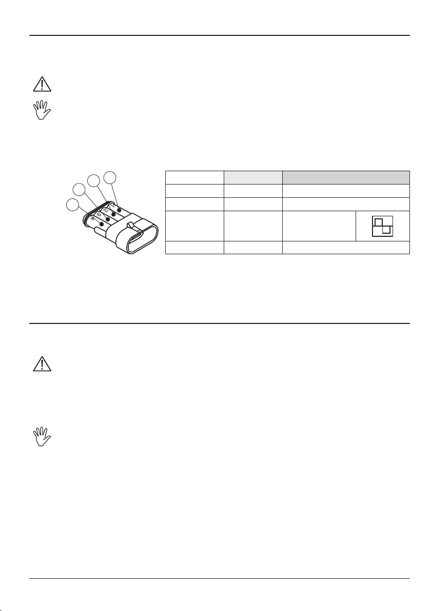
1
2
3
1
Fig. 4
2
3
4
4
Colour Position Connection
Black 1 GND
Red 2 +12 VDC
Green 3
Yellow 4 Pump control
Signal
(square wave)
It is possible to connect Orion Visual Flow to computers and screens in the Bravo series without the
"Pump Stop Kit" using the adapting cable (code 4622BA50000.110), which enables the connection
between the 4-pole connector on the owmeter and the 3-pole connector on the Bravo.
2.2 Hydraulic connections
For connection to the system, use appropriate ttings (Ref. ARAG General Catalogue).
Avoid bends and constrictions before connections and on tubes.
Regarding connections, use tubes and ttings properly sized for the operating pressure of the system.
The tightening of hose tails should be made with special metal clamps ensuring
perfect sealing even at high pressures.
The connection by means of threaded ttings should be done taking operating pressure into account.
CAUTION: For the implementation on already operating systems it is necessary to
follow all safety rules described herein.
System assembly and start-up must be carried out by expert personnel according to
the safety rules so as to ensure the same safety level of the system the owmeter is
going to be installed in.
Tab. 1
Tab. 1
5
Page 6

3 SWITCH ON
When the owmeter is turned on, after a diagnostic test, it displays the following information in
sequence:
• Software version;
• Unit of measurement;
• Indicator of data displayed.
4 PRELIMINARY SETUP FOR USE
4.1 Notes on programming
After having modied a parameter in the "OPT" Advanced menu, to return to the Main menu turn
the device off and then on again.
When you are modifying a parameter or are in a Menu other than the Main menu and you do not
press a key within 10 seconds, the display will automatically return to the Main menu.
When modifying a numerical value, keep the key pressed to enable quick modication.
4.2 "OPT" Advanced menu
Upon installation of the owmeter in the lling system some settings are
needed to properly display the lling data:
• Operation mode
• Unit of measure
• Valve operation time
To access the Advanced menu, keep the key pressed while switching ON
Fig. 6
4.3 "MODE" Operation mode
It is possible to set three different operating modes:
MODE 0 = Tank lling count with pump stop control (0000 ÷ 9999 EU: l [predened setting] - US: Gal).
MODE 1 = Flowrate display.
MODE 2 = Tank lling count with pump stop control (0 ÷ 999,9 EU: l - US: Gal).
the device until the "OPT" screen appears.
1
Access the "OPT" Advanced menu as shown in Par. 4.2.
1) Press in succession to display the enabled operation mode; the value alternates with the message
"MODE".
2) To modify the value, keep the keys pressed simultaneously until "SET" screen appears.
3) Press in succession to select the mode you wish to use.
4) To conrm the setting, keep the keys pressed simultaneously until "SAVE" screen appears.
The display alternatively ashes the set operation mode and "MODE" screen.
2 3 4
6
Fig. 7
Page 7

4.4 "UNIT" Unit of measure
It is possible to choose the units of measure for displaying data:
EU = Europa (l - l/min) [predened setting].
US = USA (Gal - Gpm).
1
Access the "OPT" Advanced menu as shown in Par. 4.2.
1) Press in sequence to display the type of current unit of measure; the value alternates with the message
"UNIT".
2) To modify the value, keep the keys pressed simultaneously until "SET" screen appears.
3) Press to select the unit of measure you wish to use.
4) To conrm the setting, keep the keys pressed simultaneously until "SAVE" screen appears.
The display alternatively ashes the set unit of measure and the "UNIT" screen.
2
3 4
4.5 "VAL" Valve operation time
This parameter lets you set the time it takes the valve installed on the system to complete its closing
operation; setting this value the owmeter enables to anticipate the exact moment in which
closing begins, thus avoiding the introduction of a greater amount of product when the set value
is reached.
VAL = 0 ÷ 20 sec.
1
2 3 4
+
Access the "OPT" Advanced menu as shown in Par. 4.2.
1) Press in succession to display the "VAL" valve operation time.
2) To modify the value, keep the keys pressed simultaneously until "SET" screen appears.
3) Press to enter the operation time value using TOT key (increase) and RESET key (decrease); keep the
keys pressed to enable quick modication.
4) To conrm the setting, keep the keys pressed simultaneously until "SAVE" screen appears.
The display alternately ashes the set operation time and "VAL" screen.
Fig. 8
Fig. 9
7
Page 8

5 USE
When using the system the owmeter sends pulses to the computer which will indicate instantaneous
owrate based on the constant value previously set.
The owmeter can only detect the passage of conductive liquids having conductivity greater
than or equal to 300 µS/cm (Ref. Table 3, Chap. 7).
- Do not subject the equipment to jets of water under pressure.
- Respect the required power supply voltage (12 Vdc).
- If arc welding is needed, make sure that the power supply to the owmeter is disconnected; if necessary disconnect power cables.
- Use the owmeter only within stated owrate limits (Ref. Table 4, Chap. 7). Outside these
limits, the owmeter may provide incorrect data, thus misleading the operator or the automatic system.
ARAG cannot be held responsible for damage caused to persons, animals or things due to
incorrect or inadequate use of the owmeter or its parts.
5.1 Mode 0 - Mode 2 Use
5.1.1 Displaying data
The following parameters can be displayed during operation:
Total liquid introduced into the tank
Instantaneous rate 0 ÷ 999,9 (EU: l/min - US: Gpm)
5.1.2 Setting the amount of liquid to load into the tank
In this operation mode the owmeter displays the total amount of liquid to load into the tank:
0 ÷ 9999 (EU: l - US: Gal) - "Mode 0"
0 ÷ 999,9 (EU: l - US: Gal) - "Mode 2"
1
2 3 4
+
Fig. 10
After having been turned on, the display shows the amount of liquid to load into the tank; to modify it,
proceed as follows:
1) Press RESET key until "FILL" screen appears.
2) Set the amount of liquid to load into the tank using TOT key (increase) and RESET key (decrease); keep
the keys pressed to enable quick modication.
3) To conrm the setting, keep the keys pressed simultaneously until "SAVE" screen appears.
4) The set amount of liquid to load into the tank is displayed preceded by "TOT" screen.
8
Page 9

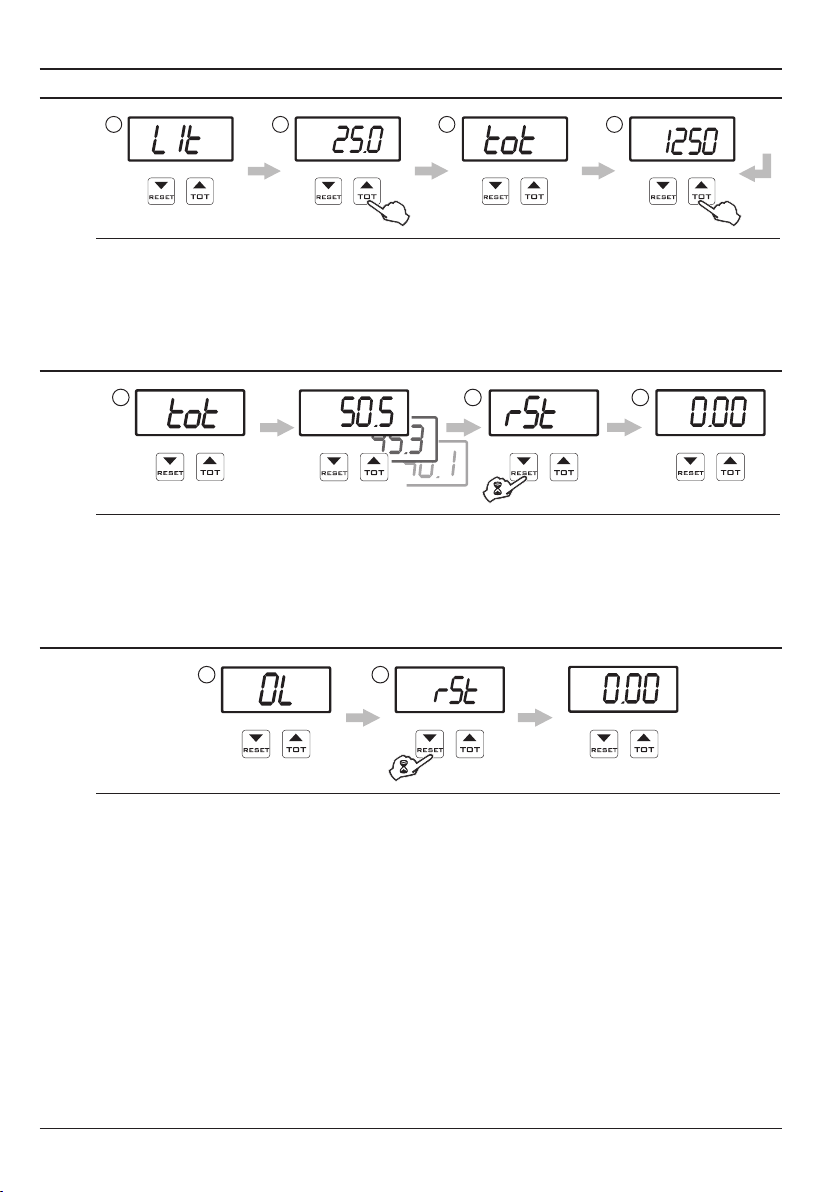
5.1.3 Mode 0 - Mode 2 Operation
1
3
1) After having been turned on, the display shows the amount of liquid to load into the tank.
2) To start the loading procedure, keep TOT key pressed until "STRT" screen appears; the amount of total
liquid loaded into the tank is displayed in real time.
3) Press TOT key to display the instantaneous rate of the liquid loaded into the tank, preceded by "LIT"
screen. Press the key again to display the amount of liquid introduced into the tank.
4) When the set value has been reached, the display alternately ashes "END" screen and the total
amount of liquid loaded into the tank.
If the Pump Stop Module is present, the lling device will automatically stop; otherwise, it should be
stopped manually.
5) To complete tank lling, press RESET key: the display will go back to the beginning of the lling procedure, showing an amount of liquid to load into the tank preceded by "TOT" screen.
4 5
2
5.1.4 Interrupting/Stopping before reaching the programmed amount
1
2 3 4
Fig. 11
Fig. 12
1) During the lling process, you can temporarily stop the pump (*) by pressing RESET key; "STRT" screen
appears.
If the instantaneous quantity is displayed, "STRT" screen does not appear: in this case, press TOT key to
display it.
2) To resume loading, press RESET key again.
3) To complete loading before reaching the set value, press the keys simultaneously until "END" screen
appears.
4) The count will end and the display will show the programmed amount of liquid.
(*) The loading can be automatically started/stopped only if owmeter is connected to ARAG Pump Stop
Module (code 4622BA50000.200). If not, the owmeter will not be able to start or stop the pump on its own
and will work as a display only.
9
Page 10
5.2 Mode 1 Operation
5.2.1 Displaying data
1
After having been turned on, the display shows the parameters read for Total liquid introduced into the
tank and Instantaneous rate using the previously set unit of measure (EU / US):
• Total liquid introduced into the tank = 0,00 ÷ 9999 (EU: l - US: Gal).
• Instantaneous rate = 0,0 ÷ 999,9 (EU: l/min - US: Gpm).
2 3 4
5.2.2 Resetting the liquid introduced into the tank counter
1
1) Access the total amount of liquid introduced into the tank display (Par. 4.2.1).
2) To reset the total amount of liquid introduced into the tank, keep RESET key pressed until "RST" screeen
appears.
3) At this point the display will show "TOT" screen followed by the reset total quantity counter.
5.3 Reaching the full scale
1
2
Fig. 13
2 3
Fig. 14
Fig. 15
1) The counter displays this screen when the full-scale value (9999 liters - Gal) is reached, and it therefore
becomes necessary to reset the counter.
2) To reset the count of the total amount of liquid introduced into the tank, keep RESET key pressed until
"RST" screen appears.
10
Page 11

6 MAINTENANCE / DIAGNOSTICS / REPAIRS
- At the end of each treatment, run clean water through the duct.
- At the end of each season or in the event of a malfunction, clean the owmeter duct using a
specic detergent.
- Do not use metal or abrasive objects for cleaning the duct.
- Do not use solvents or petrol for cleaning the external parts of the container.
6.1 Troubleshooting
FAULT CAUSE REMEDY
The owmeter does not read any
value
The value read by the owmeter is
not linear or stable
The owmeter shows incorrect data
The owmeter shows the message
No power supply • Check the owmeter wiring.
Presence of turbulence or air in the
circuit
Incorrect programming
Problems with the sensors
Problems with the owmeter
Endscale value has been
reached
• Check the circuit.
• Check programming concerning the
displayed data.
• Contact the nearest Assistance Centre.
• Reset the display following the
procedure described in the section on
the displayed value.
Tab. 2
11
Page 12

7 TECHNICAL DATA
Description Orion Visual Flow
Power supply 11 ÷ 14,5 Vdc
Max. absorption 300 mA
Minimum conductivity of liquid 300 µScm
Working temperature
Storage temperature
Dimensions 100x200x126 mm
Weight 886 ÷ 1650 g (depending on the type)
0 °C ÷ 60 °C
+32 °F ÷ +140 °F
-20 °C ÷ 60 °C
-4 °F ÷ +140 °F
Tab. 3
Flowrate
l/min US GPM pls/l pls/GAL
1 ÷ 20 0,3 ÷ 5 7 3000 11355
2,5 ÷ 50 0,6 ÷ 13 10 1200 4542
5 ÷ 100 1,3 ÷ 26 14 600 2271
10 ÷ 200 2,6 ÷ 53 18,5 300 1135
20 ÷ 400 5 ÷ 106 28 150 568
30 ÷ 600 8 ÷ 158 28 100 378
Models (*)
4621BAx1x1x 20 N + P + A
4622BAx1x1x 20 N + P + A
4622BAx7x1x 20 N + P + A
4621BAx3x3x 40 N + P + A + O
Typical error ± 0,5% of maximum value
Maximum error ± 1% of maximum value
(*) = 'x' stays for all possible variations of that position.
Internal passages
(Ø mm)
Max pressure
(bar)
Pulses/liter
Materials Legend:
Tab. 6
8 DISPOSAL AT THE END OF SERVICE
Dispose of the system in compliance with the established legislation in the country of use.
Tab. 4
N = Nylon
P = Polypropylene
A = Inox stainless steel
O = Brass
Tab. 5
12
Page 13

9 CODING TABLE
462 Single root for all subgroups
1 Body flange 463
2 Body flange 473
A Without display display 20/40 Bar
B With display display 20/40 Bar
A 316 STAINLESS STEEL electrodes
1 Flowrate 1/20 L/min
2 Flowrate 2,5/50 L/min
3 Flowrate 5/100 L/min
4 Flowrate 10/200 L/min
5 Flowrate 20/400 L/min
6 Flowrate 30/600 L/min
BODY 463
BODY 473
0 Without connection
1 Flange w/male thread
2 Flange w/female thread
3 Flange w/brass male thread
4 Flange w/brass female thread
5 Flange w/NPT male thread
6 Flange w/NPT female thread
7 Cam-Lock adapter
8 "Banjo" flange
9 ISO flange Inlet connection to Flowmeter
A Fork connection MALE flange
B
Fork connection FEMALE flange
0 See body flange
3 3/4" DN20 T3
4 1" DN25 T4
5 1"1/4 DN32 T5
6 1"1/2 DN40 / 2"STD PORTT6
7 2" DN50 / 2"FULL PORTT7
0 Without connection
1 Flange w/male thread
2 Flange w/female thread
3 Flange w/brass male thread
4 Flange w/brass female thread
5 Flange w/NPT male thread
6 Flange w/NPT female thread
7 Cam-Lock adapter
8 "Banjo" flange
9 ISO flange Outlet connection from Flowmeter
A Fork connection MALE flange
B Fork connection FEMALE flange
See body flange
0
0
3 3/4" DN20 T3
4 1" DN25 T4
5 1"1/4 DN32 T5
6 1"1/2 DN40 / 2"STD PORTT6
7 2" DN50 / 2"FULL PORTT7
462 1A A 30000
462 2B A 57616
13
Flowmeter with flange 463 for control unit, 5/100 l/min,
standard electrodes.
Flowmeter body/flange 473, 20/400 l/min, standard electrodes,
1"½ CAM-LOCK inlet connection, 1" 1/2 gas Male thread outlet.
Page 14

10 GUARANTEE TERMS
1. ARAG s.r.l. guarantees this apparatus for a period of 360 day (1 year) from the date of sale
to the client user (date of the goods delivery note). The components of the apparatus, that
in the unappealable opinion of ARAG are faulty due to an original defect in the material or
production process, will be repaired or replaced free of charge at the nearest Assistance
Centre operating at the moment the request for intervention is made.
The following costs are excluded:
- disassembly and reassembly of the apparatus from the original system;
- transport of the apparatus to the Assistance Centre.
2. The following are not covered by the guarantee:
- damage caused by transport (scratches, dints and similar);
- damage due to incorrect installation or to faults originating from insufficient or inadequate
characteristics of the electrical system, or to alterations resulting from environmental, climatic or other conditions;
- damage due to the use of unsuitable chemical products, for spraying, watering, weedkilling or any other crop treatment, that may damage the apparatus;
- malfunctioning caused by negligence, mishandling, lack of know how, repairs or modications carried out by unauthorised personnel;
- incorrect installation and regulation;
- damage or malfunction caused by the lack of ordinary maintenance, such as cleaning of
lters, nozzles, etc.;
- anything that can be considered to be normal wear and tear.
3. Repairing the apparatus will be carried out within time limits compatible with the organisational needs of the Assistance Centre.
No guarantee conditions will be recognised for those units or components that have not
been previously washed and cleaned to remove residue of the products used.
4. Repairs carried out under guarantee are guaranteed for one year (360 days) from the
replacement or repair date.
5. ARAG will not recognise any further expressed or intended guarantees, apart from those
listed here.
No representative or retailer is authorised to take on any other responsibility relative to
ARAG products.
The period of the guarantees recognised by law, including the commercial guarantees and
allowances for special purposes are limited, in length of time, to the validities given here. In
no case will ARAG recognise loss of prots, either direct, indirect, special or subsequent to
any damage.
6. The parts replaced under guarantee remain the property of ARAG.
7. All safety information present in the sales documents regarding limits in use, performance
and product characteristics must be transferred to the end user as a responsibility of the
purchaser.
8. Any controversy must be presented to the Reggio Emilia Law Court.
14
Page 15

Conformity Declaration
ARAG s.r.l.
Via Palladio, 5/A
42048 Rubiera (RE) - Italy
P.IVA 01801480359
Dichiara
che il prodotto
descrizione: Flussometro elettromagnetico
modello: Orion Visual Flow
codice: 4621BAXXXXX e 4622BAXXXXX, 4621CXXXX
risponde ai requisiti di conformità contemplati nelle seguente Direttiva Europea:
2004/108/CE e successive modificazioni
(Compatibilità elettromagnetica)
Riferimenti alle Norme Applicate:
EN ISO 14982
(Compatibilità elettromagnetica - Macchine agricole e forestali)
Rubiera, 25 Settembre 2012
Giovanni Montorsi
(Presidente)
Page 16

Only use original ARAG accessories and spare parts, to maintain safety conditions foreseen by the constructor.
Always refer to the ARAG spare parts catalogue.
42048 RUBIERA (Reggio Emilia) - ITALY
Via Palladio, 5/A
Tel. +39 0522 622011
Fax +39 0522 628944
www.aragnet.com
info@aragnet.com
D20067_GB-m05 10/2012
 Loading...