

Page 1
02
Tank Filling sysTem
462F2XXX
Software rel. 1.x
insTallaTiOn, Use anD mainTenanCe
Page 2

•
LEGEND SYMBOLS
= Generic danger
= Warning
sOmmariO
1 SAFETY GUIDELINES....................................................................................................................................3
2 PRODUCT DESCRIPTION ............................................................................................................................3
2.1 Intended use ......................................................................................................................... 3
3 INSTALLATION .................................................................................................................................................. 4
3.1 Electric connections ............................................................................................................. 5
3.2 Hydraulic connections ......................................................................................................... 6
3.2.1 General warnings ................................................................................................................6
3.2.2 Hydraulic connections ........................................................................................................ 6
3.3 Connections - general diagram ..........................................................................................6
4 USE .......................................................................................................................................................................... 7
4.1 Switch ON .............................................................................................................................. 7
4.2 Preliminary setup for use .................................................................................................... 7
4.2.1 Notes on programming ....................................................................................................... 7
4.2.2 "OPT" Advanced menu ...................................................................................................... 7
4.2.3 "MODE" Operation mode ................................................................................................... 8
4.2.4 "UNIT" Unit of measure ...................................................................................................... 8
4.2.5 "VAL" Valve operation time ................................................................................................. 9
4.3 Mode 0 - Mode 2 Use .......................................................................................................... 9
4.3.1 Displaying data .................................................................................................................... 9
4.3.2 Setting the amount of liquid to load into the tank ............................................................. 9
4.3.3 Mode 0 - Mode 2 Use ........................................................................................................10
4.3.4 Interrupting/Stopping before reaching the programmed amount ..................................10
4.4 Mode 1 Operation ...............................................................................................................11
4.4.1 Displaying data ...................................................................................................................11
4.4.2 Resetting the liquid introduced into the tank counter .....................................................11
4.5 Reaching the full scale .......................................................................................................11
5 MAINTENANCE / DIAGNOSTICS / REPAIRS ...................................................................................12
5.1 Troubleshooting .................................................................................................................. 12
6 TECHNICAL DATA ..........................................................................................................................................13
7 DISPOSAL AT THE END OF SERVICE .................................................................................................13
8 GUARANTEE TERMS ...................................................................................................................................14
This manual is an integral part of the equipment to which it refers and must accompany the equipment in
case of sale or change of ownership. Keep it for future reference; ARAG reserves the right to modify the
specications and instructions regarding the product at any time and without prior notice.
Page 3
1 Safety guidelineS
CARRYING OUT INSTALLATION AND MAINTENANCE OPERATIONS WITHOUT DISCONNECTING THE VALVE FROM ITS POWER SUPPLY MAY CAUSE SEVERE INJURY.
Do not operate the valve with no load for long periods of time, as this might damage the
components inside the valve.
ARAG can not be held responsible for direct or indirect damage caused by the type of uids
used for spraying and crop spraying applications.
These products are used under the exclusive responsibility of the operator, who must make
sure that all safety prescriptions indicated on the product label are complied with and that
suitable personal protective equipment (such as gloves, overalls, boots, helmet, etc.) is worn
at all times in compliance with the applicable legal requirements.
The tank lling system can detect the passage of conductive uids with a conductivity equal
to or higher than 300 S/cm.
- Do not place the equipment under pressurized water.
- Comply with the specied power voltage (12 Vdc).
- If arc welding is needed, make sure that the power supply to the tank lling system is
disconnected; if necessary disconnect power cables.
- Use the tank lling system only within recommended rate range (Tab. 1, Pag. 13). Outside
this range, the tank lling system may provide incorrect data, thus misleading the operator
or the automatic system.
ARAG can not be held responsible for damage caused to persons, animals or things from
the incorrect or unintended use of the tank lling system or its parts.
2 PROduCt deSCRiPtiOn
The movable tank lling system measures and displays on its screen a pre-established quantity of
uid and stops tank lling when the set quantity is reached. Through electromagnetic measurement,
the tank lling system (which features no moving mechanical parts) emits a signal that is proportional
to the ow of uid passing through it. The
owmeter displays the relevant owrate, which is calculated according to the impulses generated
and the value of the owmeter constant previously set.
2.1 Intended use
This device is designed for agricultural use. The machine is designed and built in compliance with EN ISO 14982 standard (Electromagnetic compatibility - Forestry and farming
machines), harmonized with 2004/108/EC Directive and in compliance with 2006/42/EC
Directive.
The tank lling system must not be used to measure the passage of hydrocarbons, ammable, explosive or toxic liquids. The tank lling system is not suitable for contact with
liquids for human consumption. Use for sales transactions is not allowed.
3
Page 4
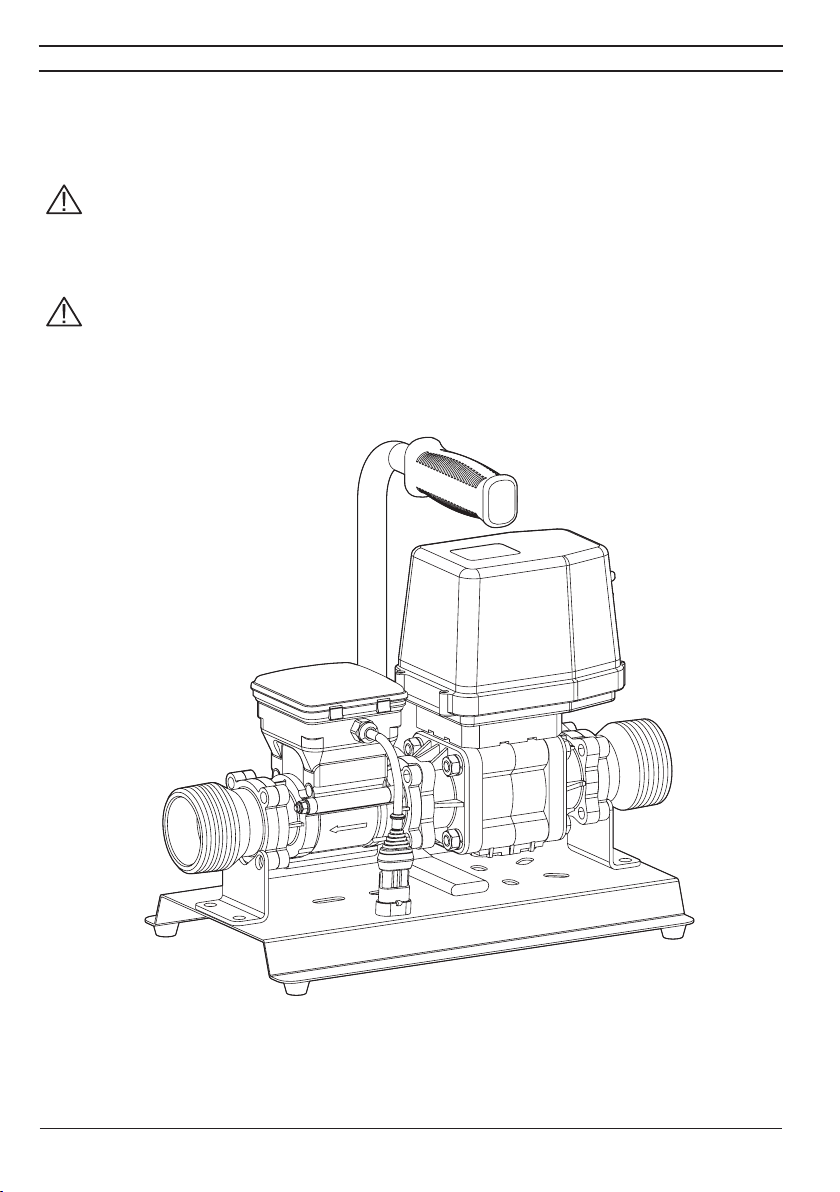
3 inStallatiOn
The tank lling system must be connected by means of suitable ttings (2" female tting with hose
tail) to a pump, which will supply the liquid to be poured into the tank.
Install the tank lling system at least 20 cm from the elements that could cause turbulence inside
the tubes (valves, bends, constrictions, etc.).
WARNING:
- Rest the tank lling system on a horizontal surface
- The system to which it is connected must have a ltering element with a lter of at
least 50 mesh, together with a safety valve to limit use pressure at the specied max.
value.
CAUTION:
ARAG is not liable for damage to the system, persons, animals or things caused by
the use of material other than specied.
Failure to observe the above instructions automatically voids the warranty.
4
Page 5
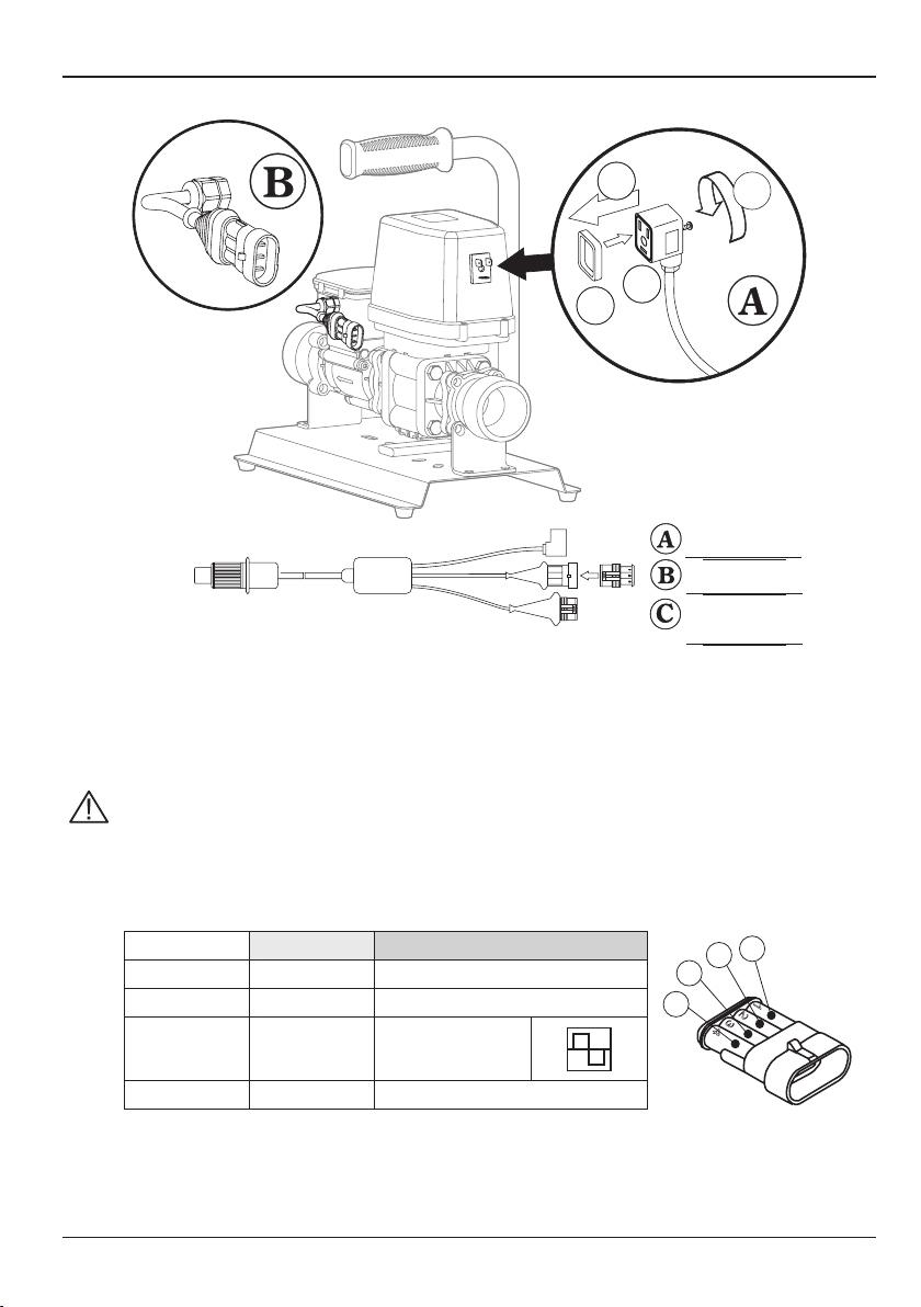
3.1 Electric connections
The tank lling system must be connected using the supplied cables.
3
4
2
1
valve cable
12 Vdc
- Remove the protection cap from the valve
- Position seal (1 in Fig. A) onto connector (2 in Fig. A), then connect the latter pressing it fully home
(3 in Fig. A). During this operation, take special care not to bend valve electric contacts.
- Fasten screw (4 in Fig. A) until it is tightened.
CAUTION: If the gasket is not positioned correctly, there may be inltrations of water
in the connector and in the valve, with the consequent risk of damage to the device.
to flowmeter
to computer
(e.g., Bravo 400s,
Bravo 300s)
DO NOT CONNECT THE POWER SUPPLY USING DIRECT FASTON CONNECTORS.
Bravo connector (C) - Connections:
Cable colour Position Connection
Blue 1 GND
Brown 2 +12 VDC
Yellow/Green 3
Black 4 Pump control
Signal
(square wave)
5
4
1
2
3
1
2
3
4
Page 6

3.2 Hydraulic connections
SPRAYINGCOMPUTER
A
B
C
D
E
3.2.1 General warnings
Avoid bends and constrictions before connections and on tubes.
Do not use the tank lling system at pressure values higher than the ones indicated
in the technical specications.
Regarding connections, use tubes and ttings properly sized for the operating pressure of the system.
WARNING: For the implementation on already operating systems it is necessary to
follow all safety rules described herein. System assembly and start-up must be carried out by expert personnel according to the safety rules so as to ensure the same
safety level of the system.
3.2.2 Hydraulic connections
Connect inlet pipes to the valve and outlet pipes to the owmeter using suitable connectors. Take
special care, where requested, to insert the supplied O-ring correctly (threaded ends). If, for any
reason, the pipes leak at connection points, apply unsintered PTFE tape to improve sealing.
3.3 Connections - general diagram
2 43 5
1
+-
12Vdc
Legend:
a Tank filling system
B Filter
C Tank filling pump
d Battery
e Computer(e.g., Bravo 400s)
6
Page 7

4 uSe
4.1 Switch ON
Upon start-up, the tank lling system performs a diagnostic test, then displays the following information in sequence:
• Software version;
• Unit of measurement;
• Indicator of data displayed.
4.2 Preliminary setup for use
4.2.1 Notes on programming
After having modied a parameter in the "OPT" Advanced menu, to return to the Main menu turn
the device off and then on again.
When you are modifying a parameter or are in a Menu other than the Main menu and you do not
press a key within 10 seconds, the display will automatically return to the Main menu.
When modifying a numerical value, keep the key pressed to enable quick modication.
4.2.2 "OPT" Advanced menu
Upon installation of the owmeter in the lling system some settings are
needed to properly display the lling data:
• Operation mode
• Unit of measure
• Valve operation time
To access the Advanced menu, keep the key pressed while switching ON
the device until the "OPT" screen appears.
7
Page 8

4.2.3 "MODE" Operation mode
It is possible to set three different operating modes:
MODE 0 = Tank lling count with pump stop control (0000 ÷ 9999 EU: l [predened setting] - US: Gal).
MODE 1 = Flowrate display.
MODE 2 = Tank lling count with pump stop control (0 ÷ 999,9 EU: l - US: Gal).
1
Access the "OPT" Advanced menu as shown in Par. 4.2.2.
1) Press in succession to display the enabled operation mode; the value alternates with the message
"MODE".
2) To modify the value, keep the keys pressed simultaneously until "SET" screen appears.
3) Press in succession to select the mode you wish to use.
4) To conrm the setting, keep the keys pressed simultaneously until "SAVE" screen appears.
The display alternatively ashes the set operation mode and "MODE" screen.
2 3 4
4.2.4 "UNIT" Unit of measure
It is possible to choose the units of measure for displaying data:
EU = Europa (l - l/min) [predened setting].
US = USA (Gal - Gpm).
1
Access the "OPT" Advanced menu as shown in Par.
1) Press in sequence to display the type of current unit of measure; the value alternates with the message
"UNIT".
2) To modify the value, keep the keys pressed simultaneously until "SET" screen appears.
3) Press to select the unit of measure you wish to use.
4) To conrm the setting, keep the keys pressed simultaneously until "SAVE" screen appears.
The display alternatively ashes the set unit of measure and the "UNIT" screen.
2
3 4
4.2.2.
.
8
Page 9

4.2.5 "VAL" Valve operation time
This parameter lets you set the time it takes the valve installed on the system to complete its closing
operation; setting this value the owmeter enables to anticipate the exact moment in which
closing begins, thus avoiding the introduction of a greater amount of product when the set value
is reached.
VAL = 0 ÷ 20 sec.
1
2 3 4
+
Access the "OPT" Advanced menu as shown in Par. 4.2.2.
1) Press in succession to display the "VAL" valve operation time.
2) To modify the value, keep the keys pressed simultaneously until "SET" screen appears.
3) Press to enter the operation time value using TOT key (increase) and RESET key (decrease); keep the
keys pressed to enable quick modication.
4) To conrm the setting, keep the keys pressed simultaneously until "SAVE" screen appears.
The display alternately ashes the set operation time and "VAL" screen..
4.3 Mode 0 - Mode 2 Use
4.3.1 Displaying data
The following parameters can be displayed during operation:
Total liquid introduced into the tank
Instantaneous rate 0 ÷ 999,9 (EU: l/min - US: Gpm)
0 ÷ 9999 (EU: l - US: Gal) - "Mode 0"
0 ÷ 999,9 (EU: l - US: Gal) - "Mode 2"
4.3.2 Setting the amount of liquid to load into the tank
In this operation mode the owmeter displays the total amount of liquid to load into the tank:
1
2 3 4
+
After having been turned on, the display shows the amount of liquid to load into the tank; to modify it,
proceed as follows:
1) Press RESET key until "FILL" screen appears.
2) Set the amount of liquid to load into the tank using TOT key (increase) and RESET key (decrease); keep
the keys pressed to enable quick modication.
3) To conrm the setting, keep the keys pressed simultaneously until "SAVE" screen appears.
4) The set amount of liquid to load into the tank is displayed preceded by "TOT" screen..
9
Page 10

4.3.3 Mode 0 - Mode 2 Use
1
3
1) After start-up the amount of uid to be poured into the tank is displayed.
2) To start the lling procedure, keep TOT key pressed until the message "STRT" appears; the value corre-
sponding to the total amount of uid poured into the tank is displayed in real time.
3) By pressing the TOT key the instant rate value of the uid poured into the tank is displayed, preceded by
"LIT" (or "GAL"). By pressing the key again, the display goes back to indicating the quantity of uid poured
into the tank.
4) Once the set value has been reached, the message "END" is displayed, alternated with the total quantity
of uid poured into the tank. The device will stop automatically the ow into the tank once the set quantity of
uid is reached.
4 5
2
4.3.4 Interrupting/Stopping before reaching the programmed amount
1
2 3 4
1) During the lling process, you can temporarily stop the pump by pressing RESET key; "STRT" screen
appears.
If the instantaneous quantity is displayed, "STRT" screen does not appear: in this case, press TOT key to
display it.
2) To resume loading, press RESET key again.
3) To complete loading before reaching the set value, press the keys simultaneously until "END" screen
appears.
4) The count will end and the display will show the programmed amount of liquid.
10
Page 11

4.4 Mode 1 Operation
4.4.1 Displaying data
1
After having been turned on, the display shows the parameters read for Total liquid introduced into the
tank and Instantaneous rate using the previously set unit of measure (EU / US):
• Total liquid introduced into the tank = 0,00 ÷ 9999 (EU: l - US: Gal).
• Instantaneous rate = 0,0 ÷ 999,9 (EU: l/min - US: Gpm).
2 3 4
4.4.2 Resetting the liquid introduced into the tank counter
1
1) Access the total amount of liquid introduced into the tank display (Par. 3.5.1).
2) To reset the total amount of liquid introduced into the tank, keep RESET key pressed until "RST" screeen
appears.
3) At this point the display will show "TOT" screen followed by the reset total quantity counter.
4.5 Reaching the full scale
1
2
2 3
1) The counter displays this screen when the full-scale value (9999 liters - Gal) is reached, and it therefore
becomes necessary to reset the counter.
2) To reset the count of the total amount of liquid introduced into the tank, keep RESET key pressed until
"RST" screen appears.
11
Page 12

5 MaintenanCe / diagnOStiCS / RePaiRS
- At the end of each treatment, run clean water through the duct.
- In case of malfunction, and at any rate at the end of every season, clean the tank lling system
pipe with a special detergent.
- Do not use metal or abrasive objects for cleaning the duct.
- Do not use solvents or petrol for cleaning the external parts of the container.
5.1 Troubleshooting
fault CauSe ReMedy
The valve leaks or the seal of the
ball is not enough
The valve does not work
The valve does not stop at the
preset point
The owmeter does not read any
value
The value read by the owmeter is
not linear or stable
The owmeter shows incorrect data
The owmeter shows the message
Presence of foreign bodies
Worn seals • Contact the nearest Assistance Centre.
Lack of power
Geared motor broken
Malfunction of the microswitches
in the geared motor
No power supply • Check the owmeter wiring.
Presence of turbulence or air in
the circuit
Incorrect programming
Problems with the owmeter • Contact the nearest Assistance Centre.
È stato raggiunto il valore di
fondoscala
• Make sure there are no foreign bodies;
if so, remove them.
• Check the connections, the cables, and
the controls. Replace the cable.
If the problem persists, contact your
nearest service centre.
• Replace the geared motor. The
instructions can be found on our Website
www.aragnet.com - ADDIN D30025
• Contact the nearest Assistance Centre.
• Check the circuit.
• Check programming concerning the
displayed data.
• Reset the display following the
procedure described in the section on the
displayed value.
12
Page 13

6 teCHniCal data
Description Tank lling system
Power supply 11 ÷ 14,5 Vdc
Max. absorption 3,3 A
Minimum conductivity of liquid 300 µScm
Valve activation time 2,3 s.
Working temperature
Storage temperature
Dimensions 375x200x346 mm
Weight 4100 g
0 °C ÷ 60 °C
+32 °F ÷ +140 °F
-20 °C ÷ 60 °C
-4 °F ÷ +140 °F
Flowrate
l/min US GPM pls/l pls/GAL
1 ÷ 20 0,3 ÷ 5 7 3000 11355
2,5 ÷ 50 0,6 ÷ 13 10 1200 4542
5 ÷ 100 1,3 ÷ 26 14 600 2271
10 ÷ 200 2,6 ÷ 53 18,5 300 11 35
20 ÷ 400 5 ÷ 106 28 150 568
30 ÷ 600 8 ÷ 158 28 100 378
Typical error ± 0,5% of maximum value
Maximum error ± 1% of maximum value
Internal passages
(Ø mm)
Pulses/liter
7 diSPOSal at tHe end Of SeRviCe
Dispose of the system in compliance with the established legislation in the country of use.
INFORMATION TO USERS – PROFESSIONAL WEEE RECYCLING
This product complies with European Directive 2002/96/EC and subsequent modifications.
At end-of-life and for disposal, the device must be taken to a waste recycling centre for electrical and electronic waste, or returned to the seller when buying a new
equivalent device.
The user is responsible for its transfer to the appropriate collection facilities.
For more detailed information concerning the collection systems available contact
your local waste disposal service.
Tab. 1
13
Page 14

8 guaRantee teRMS
1. ARAG s.r.l. guarantees this apparatus for a period of 360 day (1 year) from the date of sale
to the client user (date of the goods delivery note). The components of the apparatus, that
in the unappealable opinion of ARAG are faulty due to an original defect in the material or
production process, will be repaired or replaced free of charge at the nearest Assistance
Centre operating at the moment the request for intervention is made.
The following costs are excluded:
- disassembly and reassembly of the apparatus from the original system;
- transport of the apparatus to the Assistance Centre.
2. The following are not covered by the guarantee:
- damage caused by transport (scratches, dints and similar);
- damage due to incorrect installation or to faults originating from insufficient or inadequate
characteristics of the electrical system, or to alterations resulting from environmental, climatic or other conditions;
- damage due to the use of unsuitable chemical products, for spraying, watering, weedkilling or any other crop treatment, that may damage the apparatus;
- malfunctioning caused by negligence, mishandling, lack of know how, repairs or modications carried out by unauthorised personnel;
- incorrect installation and regulation;
- damage or malfunction caused by the lack of ordinary maintenance, such as cleaning of
lters, nozzles, etc.;
- anything that can be considered to be normal wear and tear.
3. Repairing the apparatus will be carried out within time limits compatible with the organisational needs of the Assistance Centre.
No guarantee conditions will be recognised for those units or components that have not
been previously washed and cleaned to remove residue of the products used.
4. Repairs carried out under guarantee are guaranteed for one year (360 days) from the
replacement or repair date.
5. ARAG will not recognise any further expressed or intended guarantees, apart from those
listed here.
No representative or retailer is authorised to take on any other responsibility relative to
ARAG products.
The period of the guarantees recognised by law, including the commercial guarantees and
allowances for special purposes are limited, in length of time, to the validities given here. In
no case will ARAG recognise loss of prots, either direct, indirect, special or subsequent to
any damage.
6. The parts replaced under guarantee remain the property of ARAG.
7. All safety information present in the sales documents regarding limits in use, performance
and product characteristics must be transferred to the end user as a responsibility of the
purchaser.
8. Any controversy must be presented to the Reggio Emilia Law Court.
14
Page 15

declaration of conformity and of
incorporation of partly completed machinery
ARAG s.r.l.
Via Palladio, 5/A
42048 Rubiera (RE) - Italy
P.IVA 01801480359
Dichiara
che il prodotto
descrizione: Sistema di caricamento cisterna
modello: codice: 462FXXXX
risponde ai requisiti di conformità contemplati nelle seguenti Direttive Europee:
2004/108/CE e successive modificazioni
(Compatibilità elettromagnetica)
2006/42/CE e successive modificazioni (*)
(Macchine)
Riferimenti alle Norme Applicate:
EN ISO 14982:1998
(Macchine agricole e forestali - Compatibilità elettromagnetica Metodi di prova e
criteri di accettazione)
(*) Dichiarazione ai sensi All. II B Dir. 2006/42/CE
• la documentazione tecnica pertinente è custodita da Arag, nella persona del suo legale rappresentante, sig. Giovanni Montorsi;
• ci si impegna a trasmettere, in risposta ad una richiesta adeguatamente motivata delle Autorità Nazionali, informazioni pertinenti sulle
quasi-macchine. Tale impegno comprende le modalità di trasmissione e lascia impregiudicati i diritti di proprietà intellettuale del fabbricante
della quasi-macchina;
• la conformità alla Direttiva Macchina, è applicata nei seguenti requisiti essenziali: 1.1.2, 1.1.3, 1.1.5, 1.1.6, 1.2.1, 1.2.2, 1.2.3, 1.2.4.1,
1.2.4.2, 1.2.6, 1.3.1, 1.3.2, 1.3.4, 1.3.7, 1.3.8.1, 1.4.1, 1.4.2.1, 1.5.4, 1.6.1, 1.6.5, 1.7.4, 1.7.4.1, 1.7.4.2, 1.7.4.3.
• la presente quasi-macchina non deve essere messa in servizio finchè la macchina finale in cui deve essere incorporata non sia stata
dichiarata conforme alle prescrizioni di cui Direttiva Macchine 2006/42/CE.
Rubiera, 12 Marzo 2012
Giovanni Montorsi
(Presidente e Legale Rappresentante)
Page 16

Only use original ARAG accessories and spare parts, to maintain safety conditions foreseen by the constructor.
Always refer to the ARAG spare parts catalogue.
42048 RUBIERA (Reggio Emilia) - ITALY
Via Palladio, 5/A
Tel. +39 0522 622011
Fax +39 0522 628944
http://www.aragnet.com
info@aragnet.com
D20260-m00 07/2012
 Loading...