

Page 1

02
Tank Filling sysTem
462F4501
Software rel. 1.x
insTallaTiOn, Use anD mainTenanCe
Page 2

LEGEND SYMBOL
= Generic danger
= Warning
This manual is an integral part of the equipment to which it refers and must accompany the equipment in
case of sale or change of ownership. Keep it for future reference; ARAG reserves the right to modify the
specications and instructions regarding the product at any time and without prior notice.
2
Page 3

SUMMARY
1 SAFETY GUIDELINES....................................................................................................................................4
2 PRODUCT DESCRIPTION ............................................................................................................................4
2.1 Intended use ......................................................................................................................... 4
3 INSTALLATION .................................................................................................................................................. 5
3.1 Electric connections ............................................................................................................. 6
3.2 Hydraulic connections ......................................................................................................... 7
3.2.1 General warnings ................................................................................................................7
3.2.2 Hydraulic connections ........................................................................................................ 7
3.3 Connections - general diagram .......................................................................................... 7
3.4 Monitor rotation ..................................................................................................................... 8
4 CONTROLS IN THE MENU...........................................................................................................................9
4.1 First switch on ....................................................................................................................... 9
5 MENU STRUCTURE ...................................................................................................................................... 10
6 PRELIMINARY SETUP FOR USE ........................................................................................................... 11
6.1 Operating mode selection (FILLING / FLOWRATE) .....................................................11
7 USE IN FILLING MODE ............................................................................................................................... 11
7.1 Preliminary setup .................................................................................................................11
7.1.1 Valve activation time ...........................................................................................................11
7.2 Flowmeter use (FILLING mode) ...................................................................................... 12
8 USE IN FLOWRATE MODE ........................................................................................................................ 13
8.1 Flowmeter use (FLOWRATE mode) ............................................................................... 13
8.2 Partial totalizer reset .......................................................................................................... 13
9 OTHER SETTINGS .........................................................................................................................................14
9.1 Calibration............................................................................................................................ 14
9.1.1 Automatic calibration ........................................................................................................ 14
9.1.2 Manual calibration ............................................................................................................. 15
9.2 Flowrate alarms .................................................................................................................. 15
9.3 Display .................................................................................................................................. 16
9.4 Options ................................................................................................................................. 16
9.4.1 Language ........................................................................................................................... 16
9.4.2 Units of measurement ....................................................................................................... 17
9.4.2.1 Rate units of measurement ............................................................................................... 17
9.4.2.2 Volume units of measurement .......................................................................................... 17
9.5 Test ....................................................................................................................................... 18
9.5.1 Display test......................................................................................................................... 18
9.5.2 Keys test ............................................................................................................................. 18
10 MAINTENANCE ...............................................................................................................................................19
10.1 Notes on maintenance ...................................................................................................... 19
10.2 Paddle cleaning and replacement ................................................................................... 19
10.3 OR replacement ................................................................................................................. 20
10.4 Troubleshooting .................................................................................................................. 21
11 TECHNICAL DATA .......................................................................................................................................... 22
12 DISPOSAL AT THE END OF SERVICE ................................................................................................. 23
13 GUARANTEE TERMS ...................................................................................................................................26
3
Page 4
INTRODUCTION
1 SAFETY GUIDELINES
CARRYING OUT INSTALLATION AND MAINTENANCE OPERATIONS WITHOUT DISCONNECTING THE VALVE FROM ITS POWER SUPPLY MAY CAUSE SEVERE INJURY.
Do not operate the valve with no load for long periods of time, as this might damage the
components inside the valve.
ARAG can not be held responsible for direct or indirect damage caused by the type of uids
used for spraying and crop spraying applications.
These products are used under the exclusive responsibility of the operator, who must make
sure that all safety prescriptions indicated on the product label are complied with and that
suitable personal protective equipment (such as gloves, overalls, boots, helmet, etc.) is worn
at all times in compliance with the applicable legal requirements.
The tank lling system can detect the passage of conductive uids with a conductivity equal
to or higher than 300 μS/cm.
- Do not place the equipment under pressurized water.
- Comply with the specied power voltage (12 Vdc).
- If arc welding is needed, make sure that the power supply to the tank lling system is
disconnected; if necessary disconnect power cables.
- Use the tank lling system only within recommended rate range (Tab. 1, Pag. 13). Outside
this range, the tank lling system may provide incorrect data, thus misleading the operator
or the automatic system.
ARAG can not be held responsible for damage caused to persons, animals or things from
the incorrect or unintended use of the tank lling system or its parts.
2 PRODUCT DESCRIPTION
The movable tank lling system measures and displays on its screen a pre-established quantity of
uid and stops tank lling when the set quantity is reached. Through electromagnetic measurement,
the tank lling system (which features no moving mechanical parts) emits a signal that is proportional
to the ow of uid passing through it. The
owmeter displays the relevant owrate, which is calculated according to the impulses generated
and the value of the owmeter constant previously set.
2.1 Intended use
This device is designed for agricultural use. The machine is designed and built in compliance with EN ISO 14982 standard (Electromagnetic compatibility - Forestry and farming
machines), harmonized with 2004/108/EC Directive and in compliance with 2006/42/EC
Directive.
The tank lling system must not be used to measure the passage of hydrocarbons, ammable, explosive or toxic liquids. The tank lling system is not suitable for contact with
liquids for human consumption. Use for sales transactions is not allowed.
4
Page 5
INSTALLATION
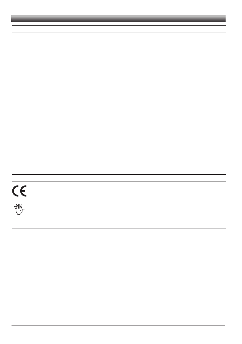
3 INSTALLATION
The tank lling system must be connected by means of suitable ttings (With female fork coupling)
to a pump, which will supply the liquid to be poured into the tank.
Install the tank lling system at least 20 cm from the elements that could cause turbulence inside
the tubes (valves, bends, constrictions, etc.).
WARNING:
- Rest the tank lling system on a horizontal surface
- The system to which it is connected must have a ltering element with a lter of at
least 50 mesh, together with a safety valve to limit use pressure at the specied max.
value (12 bar).
CAUTION:
ARAG is not liable for damage to the system, persons, animals or things caused by
the use of material other than specied.
Failure to observe the above instructions automatically voids the warranty.
5
Page 6
INSTALLATION
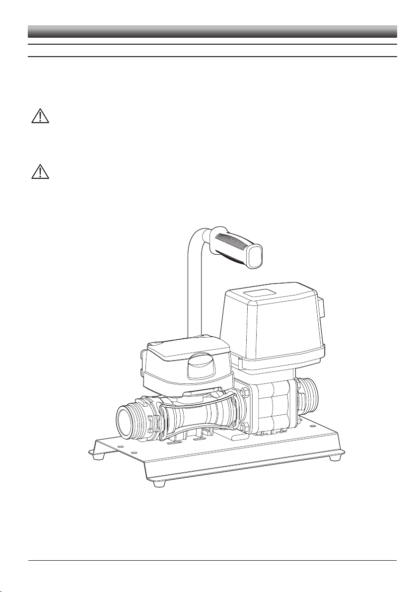
3.1 Electric connections
The tank lling system must be connected using the supplied cables.
4
3
2
1
valve cable
12 Vdc
- Remove the protection cap from the valve
- Position seal (1 in Fig. A) onto connector (2 in Fig. A), then connect the latter pressing it fully home
(3 in Fig. A). During this operation, take special care not to bend valve electric contacts.
- Fasten screw (4 in Fig. A) until it is tightened.
CAUTION: If the gasket is not positioned correctly, there may be inltrations of water
in the connector and in the valve, with the consequent risk of damage to the device.
to flowmeter
to computer
(e.g., Bravo 400s,
Bravo 300s)
DO NOT CONNECT THE POWER SUPPLY USING DIRECT FASTON CONNECTORS.
Bravo connector (C) - Connections:
Cable colour Position Connection
Grey 1 GND
Brown 2 +12 VDC
Yellow/Green 3
Black 4 Pump control
Signal
(square wave)
6
Tab. 1
4
3
2
1
Page 7
SPRAYINGCOMPUTER
A
B
C
D
E
Computer(e.g., Bravo 400s)
INSTALLATION
3.2 Hydraulic connections
3.2.1 General warnings
Avoid bends and constrictions before connections and on tubes.
Do not use the tank lling system with pressure values over 12 bar.
Regarding connections, use tubes and ttings properly sized for the operating pressure of the system.
Use Arag T6 ttings (see general catalogue) with female fork coupling. Do not use
elbow ttings.
WARNING: For the implementation on already operating systems it is necessary to
follow all safety rules described herein. System assembly and start-up must be carried out by expert personnel according to the safety rules so as to ensure the same
safety level of the system.
3.2.2 Hydraulic connections
Connect inlet pipes to the valve and outlet pipes from the owmeter, using suitable connectors.
Take special care, where requested, to insert the O-ring correctly. If, for any reason, the pipes leak
at connection points, apply unsintered PTFE tape to improve sealing.
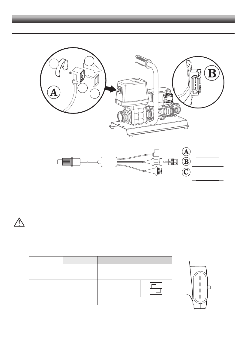
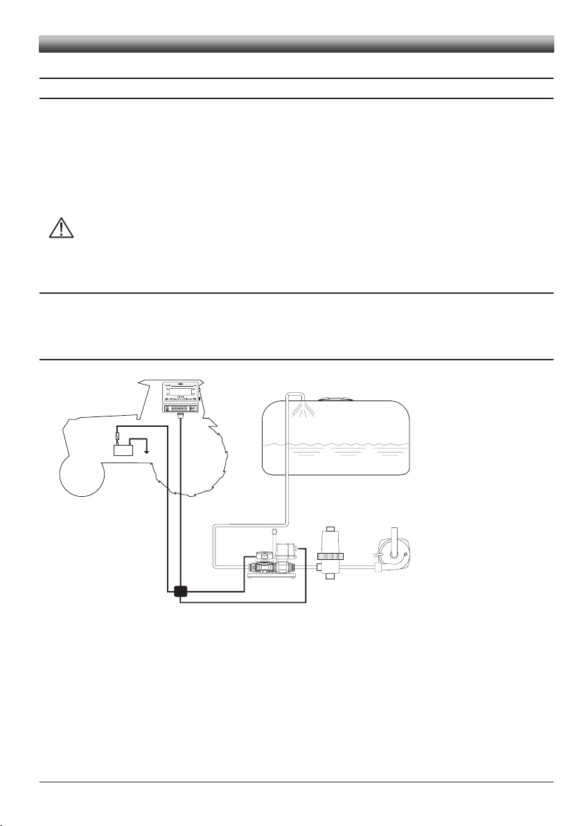
3.3 Connections - general diagram
2 43 5
1
+-
12Vdc
Legend:
A Tank filling system
B Filter
C Tank filling pump
D Battery
E
7
Page 8
INSTALLATION
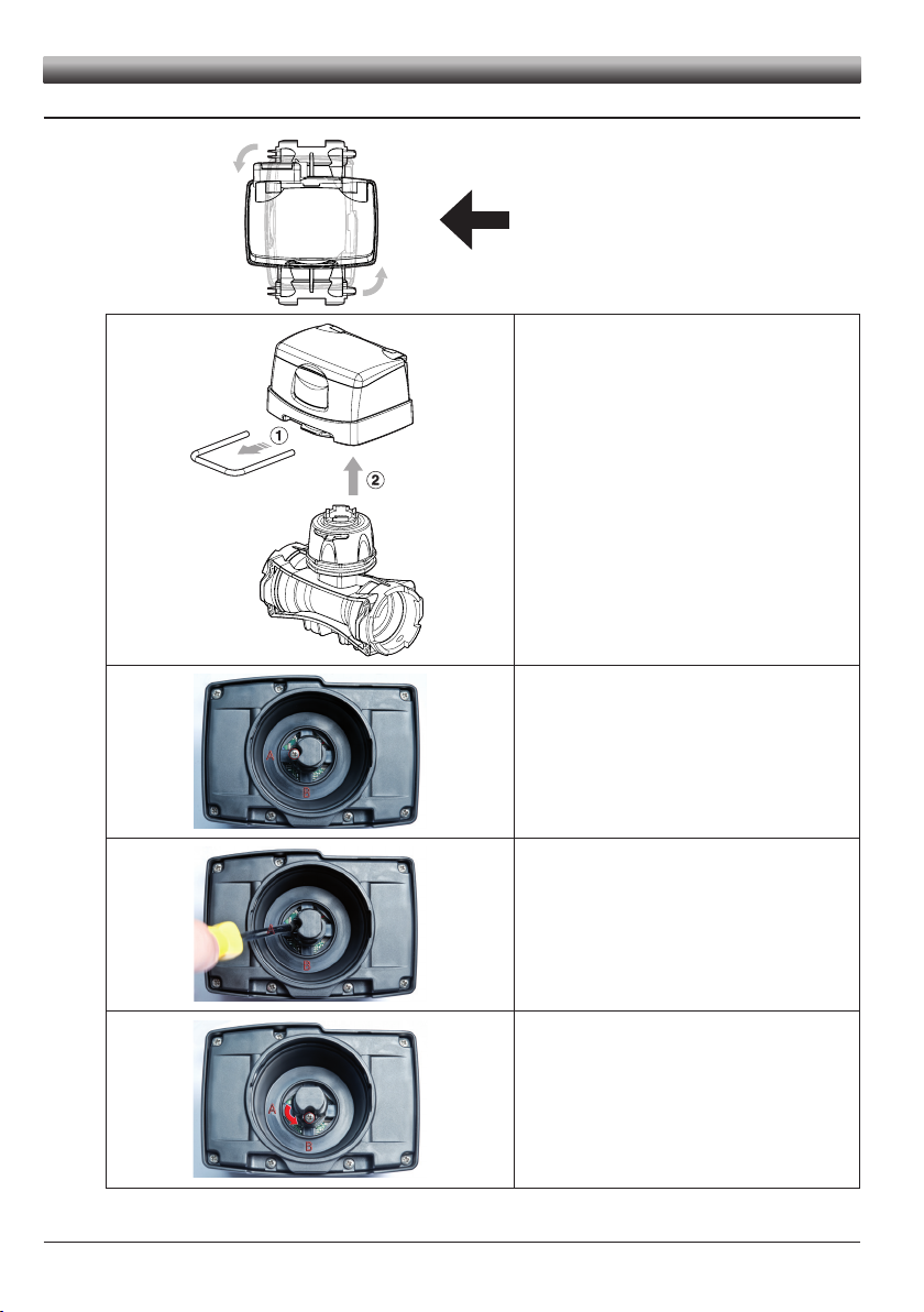
3.4 Monitor rotation
In case of vertical assembly, to simplify
the use of the DigiWolf it is possible to
rotate the monitor by 90° with respect to
the body.
1) Remove the fork from the monitor using a screwdriver.
2) Remove the monitor from the owmeter body.
If the monitor is turned upside down, the letters A and
B can be seen: these correspond to the two possible
monitor positions (parallel and perpendicular to the
body).
DigiWolf is supplied with the sensor in position A (paral-
lel to the body).
With the aid of a screwdriver, loosen the screw locking
the sensor without removing it.
Rotate the sensor anti-clockwise until reaching B stop
position.
Tighten back the screw without forcing it. The monitor
is ready to be tted in perpendicular position to the body.
Fit the monitor back on the owmeter body.
8
Page 9
4 CONTROLS IN THE MENU
0.0 l
2
1
0.0 l/min
0.0 l
2
1
0.0 l/min
Setup menu
Calibration
Flowrate alarms
Display
A
B
Flowrate constant
Min value
Max value
C
1
50000
01230
B
D
A
CONTROLS
SWITCH ON
The owmeter is turned on when powered.
Press the key to see the succession of different values written in
full (central part of the display).
Whenever the device is switched on, it will briey display its
name and software version.
ACCESS TO SETUP MENU
Press the keys for 2 seconds at the same time to access setup
menu.
SELECTION AND ACCESS TO MENU ITEMS
A Press in succession to move through items (the selected item
is highlighted with a black band)
B Press to access the selected item
Three dots under an item show the presence of
another setup menu.
MODIFYING DATA
A Press to toggle from one digit to another
B Press in succession to modify the value of the digit highlighted
by the cursor
C Press to conrm the change. The display goes back to the
previous screen.
D Press to exit current page without conrming changes.
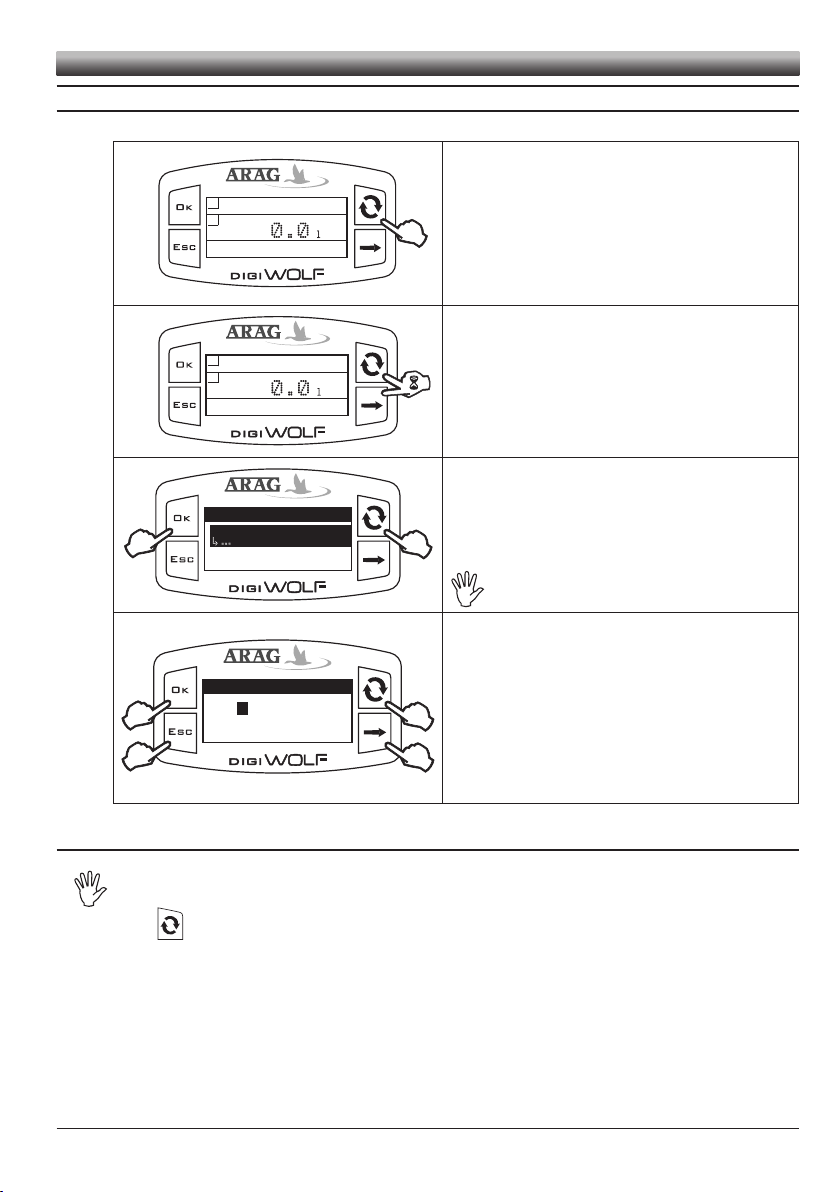
4.1 First switch on
At rst switch on, DigiWolf will run a guided procedure to set the language, two units
of measurement (owrate and volume), and the operating mode (lling or owrate).
Press key to move between items, OK to save and move to the next setting, or ESC return
to the previous setting.
9
Page 10

Setup menu
Flowrate alarms
Calibration
Flowrate alarms
Min flow alarm
Max flow alarm
Display
Setup menu
Display
Display
Brightness
Contrast
Calibration
Flowrate alarms
OFF
50%
Setup menu
Options
Options
Language
Units of measurem.
Operating mode
Flowrate alarms
Display
English
0.0 l
2
1
0.0 l/min
Setup menu
Calibration
Flowrate alarms
Display
Calibration
Auto calibration
Man. calibration
Calibration
Man. calibration
600
Auto calibration
Par. 9.1.1
Flowrate alarms
Min flow alarm
Max flow alarm
OFF
Par. 9.2
Par. 9.2
Display
Contrast
Brightness
50%
Par. 9.3
Par. 9.3
Options
Units of measurem.
Language
Units of measurem.
Flowrate
Volume
l/min
Units of measurem.
Volume
Flowrate
l
Switch on
2s.
Setup menu
Test
Test
Firmware version
Sensor frequency
Battery voltage
Display
Options
1.00
Par. 9.5
Par. 9.5
Test
Sensor frequency
Firmware version
0.0Hz
Battery voltage
Par. 9.5
Test
Battery voltage
Firmware version
Sensor frequency
Par. 9.5.1
Test
Display test
Sensor frequency
Battery voltage
Par. 9.5.2
Test
Keys test
Battery voltage
Display test
Operating mode
Par.7
Options
Operating mode
Language
Operating mode
Filling
Flowrate
Operating mode
Flowrate
Filling
Units of measurem.
Filling
Par.8
13.4V
Setup menu
Valve activ. time
Flowrate alarms
Display
0.0s
‘FILLING’ mode only
MENU
5 MENU STRUCTURE
Par. 9.4.1
Par. 9.4.2
Par. 6.1
10
Par. 9.1.2
Par. 9.4.2.1
Par. 9.4.2.2
Page 11

6 PRELIMINARY SETUP FOR USE
Options
Operating mode
Language
Units of measurem.
Filling
Operating mode
Filling
Flowrate
Setup menu
Valve activ. time
Flowrate alarms
Display
0.0s
Valve activ. time
Min value
Max value
C
0.0
9.9
.00
B
D
A
s
For a correct display of data regarding treatment, some preliminary set ups are necessary when
installing DigiWolf on farming machines.
6.1 Operating mode selection (FILLING / FLOWRATE)
DigiWolf can be used to measure the owrate of a uid in a hydraulic circuit ("Flowrate" mode), or
to control the lling of a tank by stopping the introduction of liquid once the set quantity has been
reached ("Filling" mode).
Some menu items will be available or not according to the set mode.
1) Go to the operating mode selection menu (Setup menu > Options
> Operating mode).
Under the selected item, the currently set mode will be displayed.
SETUP
2
2
7 USE IN FILLING MODE
7.1 Preliminary setup
7.1.1 Valve activation time
It is possible to set the lling valve activation time, i.e. the time interval between the sending of
valve closure signal and the ow actual interruption, so that DigiWolf can calculate the exact time
of operation and therefore the quantity introduced.
The value to be entered is indicated in the technical sheet of the lling valve installed in the system.
1) Select the desired operating mode with the key.
1
2) Press OK to save, or ESC to exit without saving.
1) Access the valve activation time menu (Setup menu > Valve activ.
time).
Under the selected item, the currently set value will be dis-
played.
2) Use the relevant keys to set the valve activation time:
A) Press to toggle from one digit to another
B) Press in succession to modify the value of the digit highlighted by
the cursor
C) Press to save changes or D) Press to exit current page without
conrming changes.
11
Page 12

Start
¬
¬
Quantity
¬
¬
o
3000.0
o
Start
¬
¬
Quantity
¬
¬
o
3000.0
Quantity
Min
Max Value
ValueC0.1
99999.9
B
D
A
3000.00
l
Start
¬
¬
Quantity
¬
¬
o
5000.0
5000.0 l
o
6.23
21.84 l/min
5000.0 l
o
15.98
Pause
5000.0 l
o
5000.0
Complété
USE (FILLING MODE)
7.2 Flowmeter use (FILLING mode)
The main screen shows the display divided into three horizontal sectors:
- upper sector:
The Start item refers to the key on the side, which allows starting the procedure
(OK key);
- central sector:
the value represents the set lling quantity (in liters).
Next to it appears the symbol
- lower sector:
The Quantity item refers to the key on the side, which allows setting the value
of tank lling (ESC key).
1) Keep ESC key pressed for two seconds to access the lling quantity set up
menu.
2) Using the suitable keys, set the lling quantity value:
A) Press to toggle from one digit to another
B) Press in succession to modify the value of the digit highlighted by the cursor
C) Press to save changes or D) Press to exit current page without conrming
changes.
3) Keep OK key pressed for two seconds. The lling process starts.
;
The display shows the following data:
- upper sector: set lling quantity;
- central sector: partial totalizer;
- lower sector: instant rate.
To see a datum in full, press the button several times until the desired value is in
the central sector of the display.
Displayed data can not be edited.
The tank lling can be interrupted at any time by pressing ESC key. The
Pause message will appear in the lower part of the display.
Press OK key to restart the lling process;
Press ESC key to denitively stop the lling; the display will go back to the main
page.
The lling stops automatically once the set quantity is reached.
The Completed message will appear in the lower part of the display.
12
Page 13

8 USE IN FLOWRATE MODE
1
0.0 l
2
1
0.0 l/min
6.23 l
2
1
21.84 l/min
6.23
6.23 l
2
1
21.84 l/min
6.23
6.23 l
2
1
21.84 l/min
0.00
50.00 l
2
1
21.84 l/min
999.99
1050.0 l
2
1
21.84 l/min
1000.0
10049 l
2
1
21.84 l/min
9999.9
10050 l
2
1
21.84 l/min
10000
...
8.1 Flowmeter use (FLOWRATE mode)
The main screen shows the display divided into three horizontal sectors.
The sectors showing the symbols
The third data represents instant rate value.
8.2 Partial totalizer reset
and 2 represent the partial totalizers, individually resettable.
Partial totalizers
Instantaneous rate
Feed some liquid to the system. The display will start to show the
increasing value of the measured quantity of liquid, and the instant
rate value.
To reset a totalizer, it is necessary to visualize it in full.
To do this, press the button several times until the value to zero is in
the central area of the display.
USE (FLOWRATE MODE)
Press ESC key for two seconds. The totalizer will zero.
- Do not place DigiWolf under pressurized water.
- Use the owmeter only within recommended rate range (Tab. 2 - Pag. 22). Beyond these
limits, the ow-meter may give out incorrect data.
- To avoid damaging the owmeter, do not exceed the maximum rate except for short periods.
ARAG can not be held responsible for damage caused to persons, animals or things from
the incorrect or unintended use of Digiwolf or its parts.
- Do not exceed the max. operation pressure (12 bar).
Display of the symbol ------ shows that the rate or the totalizer are over the max. displayable value.
Totalizers have oating points and display a max. of 5 gures. Up to 999.99 two decimals
are shown, it then drops to 1 and 0 with the transition to thousands and tens of thousands
(See g. below).
13
Page 14

End reading
0.0 l/min
¬
¬
Calibration
67.58 l
¬
¬
C
D
067.580
o
1
2
B
A
1
2
SETUP
9 OTHER SETTINGS
What follows applies to both operating modes of the owmeter.
9.1 Calibration
Rate reading may not be correct due to different system congurations (tubes,
valve, etc.). Therefore, we recommend to make a spray test; in case the measured
value is different from the real one, perform an automatic calibration procedure or
manually calculate owrate constant.
9.1.1 Automatic calibration
Make a quantity of liquid previously measured or that can be measured with another system
go through the owmeter. The greater the amount of liquid used to perform the calibration
procedure, the more accurate the calibration.
1) Access Automatic calibration menu (Setup menu > Calibration >
Auto calibration). Once inside the menu, the device is ready to
start measuring without any further controls.
2) Make the liquid go through the system. The display will start to
show the increasing value of the measured quantity of liquid. Once
liquid passage has nished, the value on the display will not change
any more.
At this point, press OK. In the lower part of the display, the message Stabilization will come up and the device will show
the screen on the side.
Setting of liquid amount actually passed through the owmeter during calibration procedure.
Display of liquid amount read by the owmeter during calibration procedure.
3) Using the keys, enter the values of the liquid quantity previously measured:
A) Press to toggle from one digit to another
B) Press in succession to modify the value of the digit highlighted by the cursor
C) Press to complete calibration procedure, or D) Press for 1 sec. to cancel calibration procedure.
If, after starting calibration, the device does not sense any ow passage (and the display
remains in 0), press OK to exit the calibration procedure without saving.
If the device continues to sense the liquid ow after pressing OK, after a few seconds
the error message Stop flow!will be displayed.
Once the ow has been interrupted, the reading will stabilize as by standard procedure.
14
Page 15

9.1.2 Manual calibration
Calibration
Man. calibration
Auto calibration
600
Flowrate constant
Min value
Max value
C
1
50000
B
D
A
06000
APPROXIMA
TE CONST
ANT
XXX
Flowrate alarms
Min flow alarm
Max flow alarm
6.00/min
Min flow alarm
Min value
Max value
0.1
99999.9
OFF
o
Min flow alarm
Min value
Max value
C
0.1
99999.9
B
D
A
0040.00
l/min
o
To set the owrate constant manually, calculate and set the correct constant using the following
formula:
SETUP
[amount measured by device]
[actually delivered quantity]
x [constant indicated on flowmeter body]
1) Access Manual calibration menu (Setup menu > Calibration > Man. calibration).
In Calibration menu, selecting Manual calibration, under the item the cur-
rently set constant will be displayed.
Press OK key to access value modication.
2) Using the suitable keys, set the value of the owmeter constant:
A) Press to toggle from one digit to another
B) Press in succession to modify the value of the digit highlighted by the cursor
C) Press to save changes or D) Press to exit current page without conrming
changes. Refer to the label on the body
The owmeter body must be assembled with the arrow on the
label facing the ow direction.
APPROXIMATE CONSTANT
XXX
CODE Approximate constant
4627405A 250
4627506A 132
4627707A 64
9.2 Flowrate alarms
Set the minimum and maximum values beyond which the display must show an alarm message.
1) Access Flowrate alarms menu (Setup menu > Flowrate alarms).
Min. and max. owrate alarms setting is done in the same way.
Under the selected item, the currently set value will be displayed.
Press OK key to access modication of the selected item.
and
2) To activate the alarm, press
message OFF disappears and owrate alarm value is displayed.
keys at the same time until the
Carry out the same procedure to deactivate owrate alarm again.
3) Set owrate alarm value:
A) Press to toggle from one digit to another
B) Press in succession to modify the value of the digit highlighted by the cursor
C) Press to save changes of D) Press to exit current page without conrming
changes.
15
Page 16

SETUP
Display
Brightness
Contrast
50%
Brightness
50%
1
2
2
Options
Language
Units of measurem.
English
Language
Italiano
English
Español
Português
9.3 Display
Adjust display brightness and contrast.
9.4 Options
9.4.1 Language
Set desired language and units of measurement.
Access display menu (Setup menu > Display).
Brightness and contrast adjustment is done in the same way.
Under the selected item, the currently set value will be displayed.
Press OK key to access modication of the selected item.
1) Set the value using the key. Each time it is pressed, the value will increase
by 10% until reaching 100% and then starts back from 0.
2) Press the OK key to save, or ESC to exit without saving.
Access language setup menu (Setup menu > Options > Language).
Under the selected item, the currently set value will be displayed.
Press OK key to access language selection.
2
2
1) Select language using the key.
1
2) Press the OK key to save, or ESC to exit without saving
16
.
Page 17

9.4.2 Units of measurement
Units of measurem.
Flowrate
Volume
l/min
Flowrate
l/min.
GPM
m/h
3
Units of measurem.
Volume
Flowrate
l
Volume
l
gal
m
3
Set units of measurement for owrate values and volume read by the device.
9.4.2.1 Rate units of measurement
Access instant rate units of measurement menu (Setup menu > Options > Units
of measurem. > Flowrate).
Under the selected item, the currently set value will be displayed.
Press OK key to access owrate units of measurement selection.
SETUP
2
2
9.4.2.2 Volume units of measurement
2
2
1) Select measurement unit using key.
1
2) Press OK key to save, or ESC to exit without saving.
Access volume units of measurement menu (Setup menu > Options > Units of
measurem. > Volume).
Under the selected item, the currently set value will be displayed.
Press OK key to access volume units of measurement selection.
1) Select measurement unit using key.
1
2) Press OK key to save, or ESC to exit without saving.
17
Page 18

Test
Display test
Sensor frequency
Battery voltage
Test
Keys test
Battery voltage
Display test
1
2
1
1
SETUP
9.5 Test
In this menu is it possible to see some information and run a device operation test:
- Firmware version:
The display shows the rmware version installed on the device.
- Sensor frequency:
In the presence of ow passage, the display shows in real time the frequency of the signal from the
sensor reading the owrate.
- Battery voltage:
the display shows the device supply voltage level.
9.5.1 Display test
Display test checks the correct operation of the display on the device.
Access display test menu (Setup menu > Test > Display test).
Press OK key to access the test.
The display shows all pixels on.
Press ESC key to return to the previous screen.
9.5.2 Keys test
Keys test checks the correct operation of the keys on the device.
Access keys test menu (Setup menu > Test > Keys test).
Press OK key to access the test.
1) Pressing one key, the corresponding portion of the display will light up.
2) To exit, press ESC key: after lighting up the corresponding portion of the
display, it will return to the previous screen.
18
Page 19

MAINTENANCE
10 MAINTENANCE
10.1 Notes on maintenance
- At the end of each treatment, run clean water through the tubes.
- Clean the tank lling system pipe with a special detergent on a regular basis.
- Clean (and if necessary, replace) the owmeter paddle on a regular basis (page 19, chap 10.2)
- Do not use metal or abrasive objects to clean the paddle.
- Do not use solvents or fuel to clean the case outer surface.
10.2 Paddle cleaning and replacement
4
sblocca
2
4
1) Remove the fork from the monitor using a screwdriver.
2) Remove the monitor from the owmeter body.
3) Unscrew the ring nut in a counter clockwise direction and remove the sensor housing block from
the owmeter body.
4) With half a rotation, remove the paddle group from the sensor housing block in a counter clockwise
direction.
5) Immerse the paddle group in detergent liquid for several hours.
6) Wash the paddle group thoroughly with running water and check its correct operation. If necessary,
replace the complete paddle group with its suitable spare part (code 4626000.500).
7) Ret the paddle group on the electronic sensor with a clockwise rotation until it clicks in place.
blocca
7
CONTINUES
19
Page 20

APPROXIMA
TE CONST
ANT
XXX
MAINTENANCE
2
1
Arrows direction on the body must
correspond to the one on the label
8) Ret the sensor housing block on the owmeter body tightening the ring nut in a clockwise
direction until it stops paying attention to keep the arrow on the coupling facing the ow
direction.
10.3 OR replacement
With the removed sensor housing block (see Par. 10.2) proceed as follows:
1) Remove the fork from the ring nut using a screwdriver.
2) Remove the ring nut.
- OR replacement:
Replace the ORs (Code G10051V - ARAG spare parts catalogue).
3) Ret the sensor housing block ensuring that the fork is correctly
inserted in the ring nut.
20
Page 21

10.4 Troubleshooting
FAULT CAUSE REMEDY
The valve leaks or the seal of the
ball is not enough
The valve is not working and the
display is off
The valve does not work Geared motor broken
The valve does not stop at the
preset point
Totalizers do not progress during the
passage of liquid.
Displayed owrate is not stable
Presence of foreign bodies
Worn seals • Contact your nearest assistance centre.
Lack of power
Malfunction of the microswitches
in the geared motor
Rate is beyond operation limits of
the owmeter
The paddle-wheel is locked
Presence of turbulence or air in
the circuit
Worn paddle • Replace the paddle.
MAINTENANCE
• Make sure there are no foreign bodies;
if so, remove them.
• Check the connections, the cables, and
the controls. Replace the cable.
If the problem persists, contact your
nearest service centre.
• Replace the geared motor. The
instructions can be found on our Website
www.aragnet.com - ADDIN D30025.
• Contact your nearest assistance centre.
• The model of the owmeter is not ad-
equate for the owrate to be measured.
Replace the owmeter.
• Clean or replace the paddle-wheel group
if necessary.
• Check the circuit.
21
Page 22

TECHNICAL DATA
11 TECHNICAL DATA
Data Min. Max. Default UoM Notes
Calibration Manual calibration 1 50,000 600 -- --
The alarm can be deactivated
setting the value "OFF"
The alarm can be deactivated
setting the value "OFF"
Language settings: Italiano,
English, Español,
Português, Français, Deutsch,
Cesky, Polski,
, Русский, Magyar.
ニホン
Units of measurement settings: l/min, GPM, m
Units of measurement settings: l, gal, m
Flowrate alarms
Display
Filling
Options
Min. owrate alarm 0.1 99999.9 OFF l/min.
Max. owrate alarm 0.1 999999.9 OFF l/min.
Brightness 0% 100% 50% % --
Contrast 0% 100% 50% % --
Valve activation time 0.0 9.9 0.0 sec.
Filling quantity 0.1 99999.9 3000.0 litres
Language - - English -
Rate units of
measurement
Volume units of
measurement
- - l/min. -
- - litres -
Description Tank lling system
Power supply 12 Vdc ± 10%
Short circuit protection •
Flowrate signal square wave (0 ÷ V suppl.)
Max. frequency 1,2 KHz
Max. absorption 3 A
Working temperature
0 °C ÷ 60 °C
+32 °F ÷ +140 °F
Storage temperature -30 °C ÷ 80 °C / -22 °F ÷ +176 °F
Dimensions 330x200x346 mm
Weight 3500 g
3
/h
3
Tab 2
22
Page 23

12 DISPOSAL AT THE END OF SERVICE
Dispose of the system in compliance with the established legislation in the country of use.
INFORMATION TO USERS – PROFESSIONAL WEEE RECYCLING
This product complies with European Directive 2002/96/EC and subsequent modifications. At end-of-life and for disposal, the device must be taken to a waste recycling centre for electrical and electronic waste, or returned to the seller when buying a new equivalent device.
The user is responsible for its transfer to the appropriate collection facilities. For more detailed information concerning the collection systems available contact your local waste disposal service.
23
Page 24

Notes
24
Page 25

Notes
25
Page 26

GUARANTEE
13 GUARANTEE TERMS
1. ARAG s.r.l. guarantees this apparatus for a period of 360 day (1 year) from the date of sale to
the client user (date of the goods delivery note).
The components of the apparatus, that in the unappealable opinion of ARAG are faulty
due to an original defect in the material or production process, will be repaired or replaced
free of charge at the nearest Assistance Centre operating at the moment the request for
intervention is made. The following costs are excluded:
- disassembly and reassembly of the apparatus from the original system;
- transport of the apparatus to the Assistance Centre.
2. The following are not covered by the guarantee:
- damage caused by transport (scratches, dints and similar);
- damage due to incorrect installation or to faults originating from insufficient or inadequate
characteristics of the electrical system, or to alterations resulting from environmental, climatic or other conditions;
- damage due to the use of unsuitable chemical products, for spraying, watering, weedkilling
or any other crop treatment, that may damage the apparatus;
- malfunctioning caused by negligence, mishandling, lack of know how, repairs or modications carried out by unauthorised personnel;
- incorrect installation and regulation;
- damage or malfunction caused by the lack of ordinary maintenance, such as cleaning of
lters, nozzles, etc.;
- anything that can be considered to be normal wear and tear.
3. Repairing the apparatus will be carried out within time limits compatible with the organisational needs of the Assistance Centre.
No guarantee conditions will be recognised for those units or components that have not
been previously washed and cleaned to remove residue of the products used.
4. Repairs carried out under guarantee are guaranteed for one year (360 days) from the replacement or repair date.
5. ARAG will not recognise any further expressed or intended guarantees, apart from those
listed here.
No representative or retailer is authorised to take on any other responsibility relative to
ARAG products.
The period of the guarantees recognised by law, including the commercial guarantees and
allowances for special purposes are limited, in length of time, to the validities given here. In
no case will ARAG recognise loss of prots, either direct, indirect, special or subsequent to
any damage.
6. The parts replaced under guarantee remain the property of ARAG.
7. All safety information present in the sales documents regarding limits in use, performance
and product characteristics must be transferred to the end user as a responsibility of the
purchaser.
8. Any controversy must be presented to the Reggio Emilia Law Court.
26
Page 27

declaration of conformity and of
incorporation of partly completed machinery
ARAG s.r.l.
Via Palladio, 5/A
42048 Rubiera (RE) - Italy
P.IVA 01801480359
Dichiara
che il prodotto
descrizione: Sistema di caricamento cisterna
modello: codice: 462FXXXX
risponde ai requisiti di conformità contemplati nelle seguenti Direttive Europee:
2004/108/CE e successive modificazioni
(Compatibilità elettromagnetica)
2006/42/CE e successive modificazioni (*)
(Macchine)
Riferimenti alle Norme Applicate:
EN ISO 14982:1998
(Macchine agricole e forestali - Compatibilità elettromagnetica Metodi di prova e
criteri di accettazione)
(*) Dichiarazione ai sensi All. II B Dir. 2006/42/CE
• la documentazione tecnica pertinente è custodita da Arag, nella persona del suo legale rappresentante, sig. Giovanni Montorsi;
• ci si impegna a trasmettere, in risposta ad una richiesta adeguatamente motivata delle Autorità Nazionali, informazioni pertinenti sulle
quasi-macchine. Tale impegno comprende le modalità di trasmissione e lascia impregiudicati i diritti di proprietà intellettuale del fabbricante
della quasi-macchina;
• la conformità alla Direttiva Macchina, è applicata nei seguenti requisiti essenziali: 1.1.2, 1.1.3, 1.1.5, 1.1.6, 1.2.1, 1.2.2, 1.2.3, 1.2.4.1,
1.2.4.2, 1.2.6, 1.3.1, 1.3.2, 1.3.4, 1.3.7, 1.3.8.1, 1.4.1, 1.4.2.1, 1.5.4, 1.6.1, 1.6.5, 1.7.4, 1.7.4.1, 1.7.4.2, 1.7.4.3.
• la presente quasi-macchina non deve essere messa in servizio finchè la macchina finale in cui deve essere incorporata non sia stata
dichiarata conforme alle prescrizioni di cui Direttiva Macchine 2006/42/CE.
Rubiera, 12 Marzo 2012
Giovanni Montorsi
(Presidente e Legale Rappresentante)
Page 28

Only use original ARAG accessories and spare parts, to maintain safety conditions foreseen by the constructor.
Always refer to the ARAG spare parts catalogue.
42048 RUBIERA (Reggio Emilia) - ITALY
Via Palladio, 5/A
Tel. +39 0522 622011
Fax +39 0522 628944
http://www.aragnet.com
info@aragnet.com
D20261-m00 09/2012
 Loading...