

Page 1
digi
CELL POWERED VERSION
4628405
4628506
4628707
Software rel. 1.0X
INSTALLATION, USE AND MAINTENANCE
Page 2

LEGEND SYMBOLS
=
Generic danger
=
Warning
This manual is an integral part of the equipment to which it refers and must accompany the equipment in case of sale or
change of ownership. Keep it for future reference; ARAG reserves the right to modify the specications and instructions
regarding the product at any time and without prior notice.
Page 3

CONTENTS
1 Product description ........................................................................................................................................................... 4
1.1 Intended use............................................................................................................................................................... 4
2 Flowmeter assembly ......................................................................................................................................................... 4
2.1 Monitor rotation .......................................................................................................................................................... 5
2.2 Dimensions (mm) ....................................................................................................................................................... 6
2.3 Hydraulic connections ................................................................................................................................................ 6
2.3.1 Hydraulic connection for brass/fork connections ....................................................................................................... 6
2.4 Power supply .............................................................................................................................................................. 7
2.4.1 Battery replacement ................................................................................................................................................... 7
3 Controls in the menu ......................................................................................................................................................... 8
Menu structure ................................................................................................................................................................... 9
4 Preliminary setup for use................................................................................................................................................ 10
4.1 Calibration ................................................................................................................................................................ 10
4.1.1 Automatic calibration ................................................................................................................................................10
4.1.2 Manual calibration .....................................................................................................................................................11
4.2 Flowrate alarms ........................................................................................................................................................ 12
4.3 Display ...................................................................................................................................................................... 12
4.4 Energy saving ........................................................................................................................................................... 13
4.5 Options ..................................................................................................................................................................... 13
4.5.1 Language ................................................................................................................................................................. 13
4.5.2 Units of measurement .............................................................................................................................................. 14
4.5.2.1 Rate units of measurement ................................................................................................................................... 14
4.5.2.2 Volume units of measurement ............................................................................................................................... 14
4.6 Test ........................................................................................................................................................................... 15
4.6.1 Display test ............................................................................................................................................................... 15
4.6.2 Keys test ................................................................................................................................................................... 15
5 Use .............................................................................................................................................................................. 16
5.1 Partial totalizer reset ................................................................................................................................................. 16
6 Cleaning and repair ......................................................................................................................................................... 17
6.1 Troubleshooting ........................................................................................................................................................ 17
6.2 Paddle cleaning and replacement ............................................................................................................................ 18
6.3 OR replacement ....................................................................................................................................................... 19
7 Technical data ................................................................................................................................................................. 20
8 Disposal at the end of service ....................................................................................................................................... 20
9 Guarantee terms .............................................................................................................................................................. 22
3
Page 4
APPROXIMA
TE CONST
ANT
XXX
INTRODUCTION
1 PRODUCT DESCRIPTION
DigiWolf is a battery powered paddle owmeter capable of measuring the rate of a uid in a hydraulic circuit, and it can display the results of these
measurements.
1.1 Intended use
This device is designed to work on agricultural machinery for crop spraying applications.
The machine is designed and built in compliance with EN ISO 14982 standard (Electromagnetic compatibility - Forestry and
farming machines), harmonized with 2004/108/EC Directive.
The owmeter must not be used to measure the passage of hydrocarbons, ammable, explosive or toxic liquids. The owmeter
is not suitable for contact with liquids for human consumption.
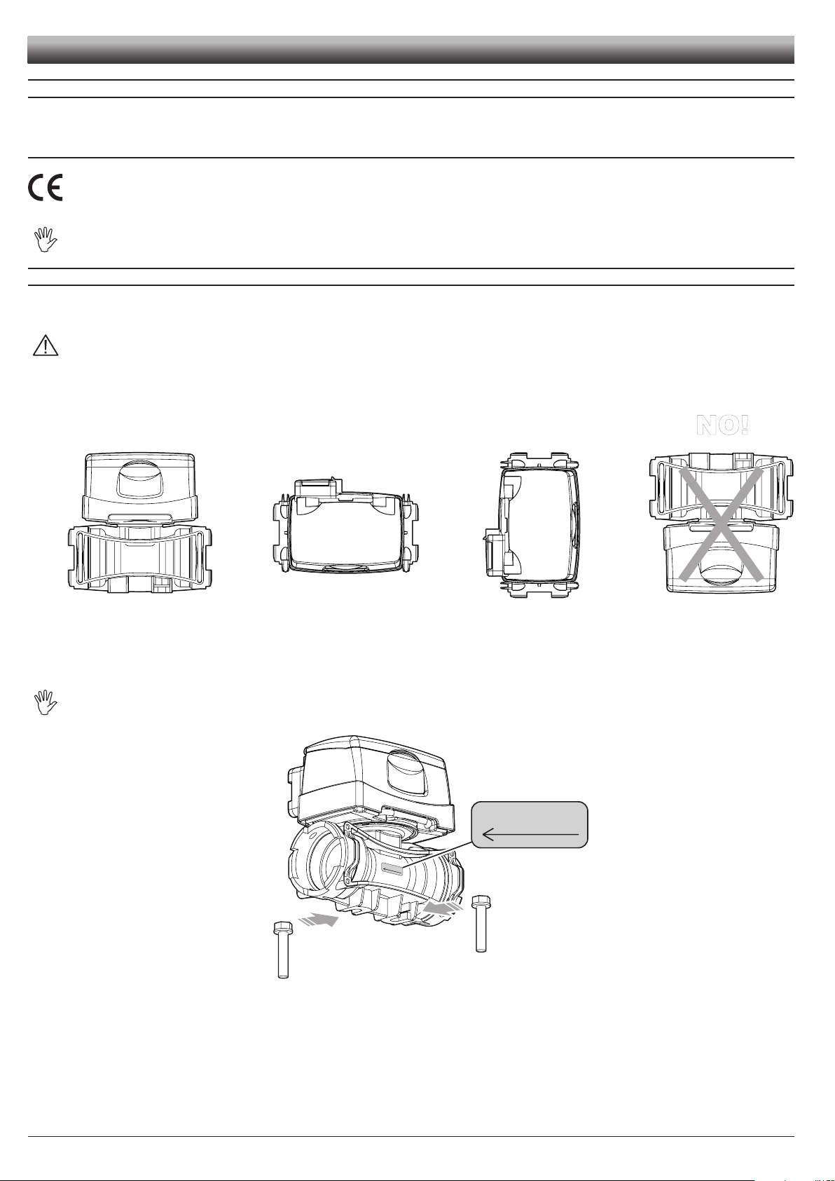
2 FLOWMETER ASSEMBLY
Install the owmeter at least 20 cm from the elements that could cause turbulence inside the tubes (valves, bends, constrictions, etc.).
The owmeter can be installed in a vertical or horizontal position.
CAUTION:
- Do not install the owmeter with the connector facing downwards (Fig. 1).
- The system must have a ltering element with a lter of at least 50 mesh, together with a safety valve to limit use pressure at
the specied max. valve (Tab. 2 - Par. 2.3.1).
OK
Assemble the owmeter using the suitable mounting parts (Fig. 2): t the bolts (M8) in their seats, then make them slide to their stop position to prevent
them from coming out.
OK OK
NO!
Fig. 1
The owmeter body must be assembled with the arrow on the label facing the ow direction.
APPROXIMATE CONSTANT
XXX
Fig. 2
4
Page 5
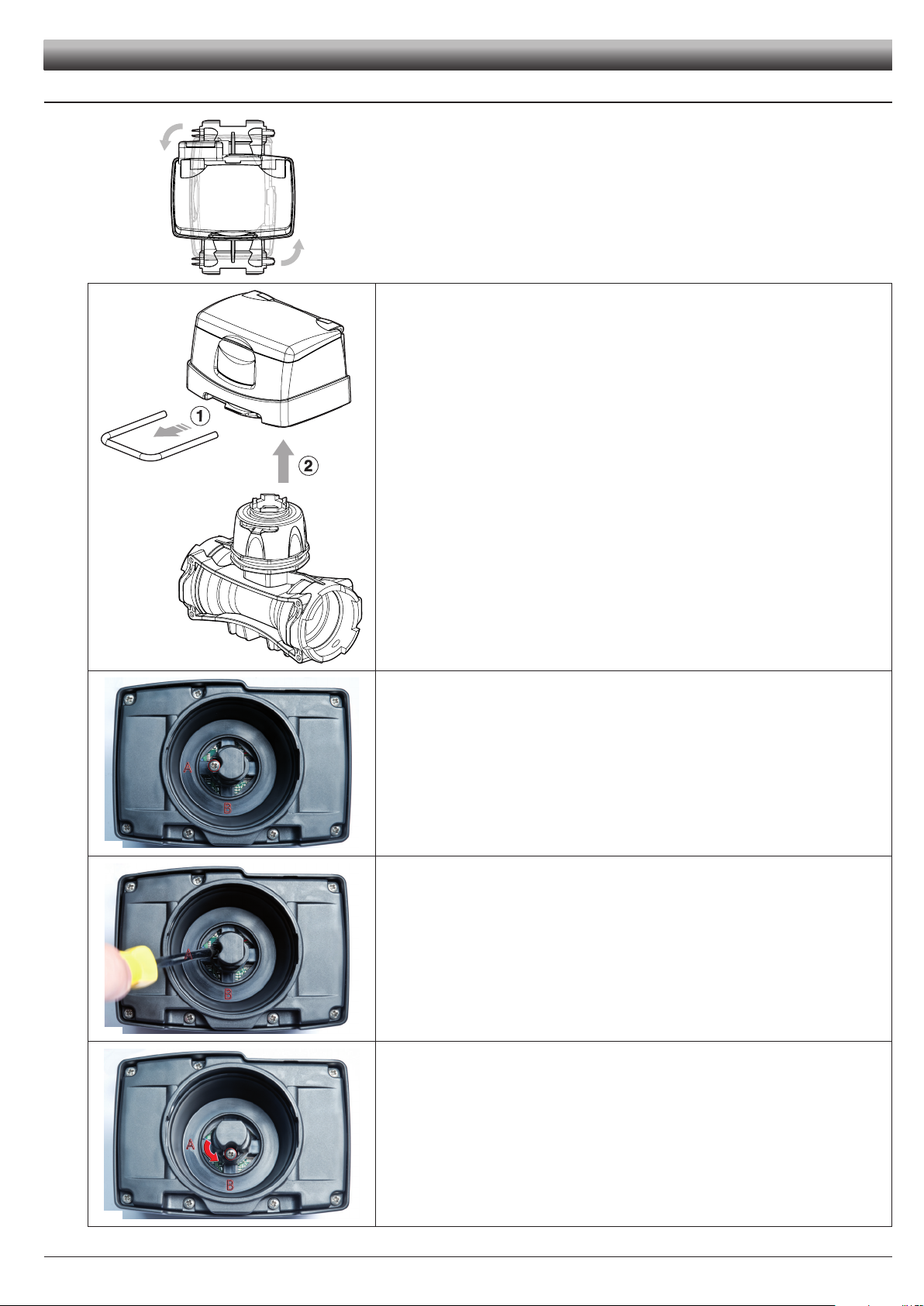
2.1 Monitor rotation
Fig. 3
INSTALLATION
In case of vertical assembly, to simplify the use of the DigiWolf it is possible to rotate the
monitor by 90° with respect to the body (Fig. 3).
1) Remove the fork from the monitor using a screwdriver.
2) Remove the monitor from the owmeter body.
Fig. 4
Fig. 5
Fig. 6
If the monitor is turned upside down, the letters A and B can be seen: these correspond to
the two possible monitor positions (parallel and perpendicular to the body).
DigiWolf is supplied with the sensor in position A (parallel to the body).
With the aid of a screwdriver, loosen the screw locking the sensor without removing it.
Rotate the sensor anti-clockwise until reaching B stop position.
Fig. 7
Tighten back the screw without forcing it. The monitor is ready to be tted in perpendicular position to the body.
Fit the monitor back on the owmeter body.
5
Page 6
INSTALLATION
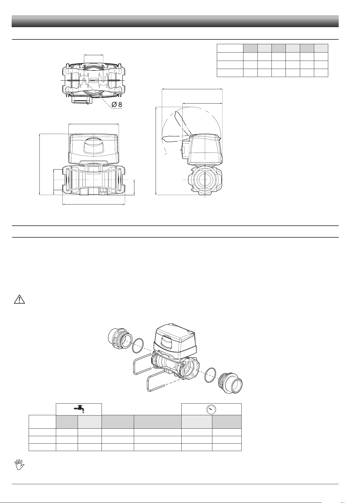
2.2 Dimensions (mm)
A
T
2.3 Hydraulic connections
E
120
B
D
C
143
CODE A B C D E T
4628405 140 128 205 31 41 T5
4628506 145 148 210 36 45 T6
4628707 157 162 222 41 45 T7
Tab. 1
95
Fig. 8
2.3.1 Hydraulic connection for brass/fork connections
Avoid bends and constrictions before connections and on tubes.
Use ARAG connections with their suitable OR with MALE CONNECTIONS [T connections - General Catalogue (Tab. 2)].
The tubes must be able to stand a pressure of at least twice the max. operation pressure of the owmeter (Tab. 2)
CONSIDERING THE OPERATION PRESSURES WITHIN THE SYSTEM.
Hose tail tightening must be done using the suitable metal clamps to ensure perfect mechanical sealing, even at high pressures.
The connection with threaded connectors must be done paying attention to operation pressure.
CAUTION: For the implementation on already operating systems it is necessary to follow all safety rules described herein.
System assembly and start-up must be carried out by expert personnel according to the safety rules so as to ensure the same
safety level of the system the owmeter is going to be installed in.
After connection, check for the perfect sealing of the tubes and fork connections.
Fig. 9
CODE l/min. US GPM Connection Ø equivalent (inch)
4628405 10-200 2.6-53 T5 F 1 1/4" 20 290
4628506 20-400 5-106 T6 F 1 1/2" 12 174
4628707 40-800 10-210 T7 F 2" 7 130
The diameter in inches (Ø equivalent) is given only as an indication of the typical passage of the owmeter body. Actually, it is
possible to choose different sizes depending on the fork connection used.
Max. p
(bar)
6
Max. p
(PSI)
Tab. 2
Page 7
0.0 l/min
1
2
0.0 l
INSTALLATION
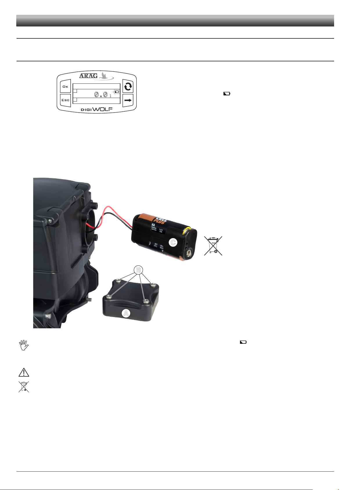
2.4 Power supply
DigiWolf is powered by 2 AA batteries type LR6 (alkaline) or FR6 (Li-Fe S2).
2.4.1 Battery replacement
When the batteries are low, the symbol will blink on the display.
Fig. 10
To insert or replace the batteries, proceed as follows:
1) Remove the lid of the battery compartment (A) loosening the 4 screws (B);
2) Remove the battery support (C) and replace the batteries, respecting their polarity (as indicated).
3) Fit the support back in its housing and ret the lid by tightening the 4 screws without forcing them, taking care not to crush or break
the wires in the battery case and that the lid seal remains in its seat.
C
B
Fig. 11
A
To avoid damaging the device, replace low batteries as soon as this symbol is displayed .
Remember to remove the batteries when the device is not going to be in use for a long period.
Use only the recommended type of batteries. Do not use combinations of different types of batteries (old and new, carbon and
alkaline, etc.). Do not try to recharge the batteries.
ARAG is not liable for damage to the equipment, persons, animals or things caused by failure to observe the above instructions.
Do not dispose of exhausted batteries in the environment. Dispose of in a suitable container.
7
Page 8
0.0 l
2
1
0.0 l/min
0.0 l
2
1
0.0 l/min
Setup menu
Calibration
Flowrate alarms
Display
A
B
Flowrate constant
Min value
Max value
C
1
50000
01230
B
D
A
SETUP
3 CONTROLS IN THE MENU
Fig. 12
Fig. 13
Fig. 14
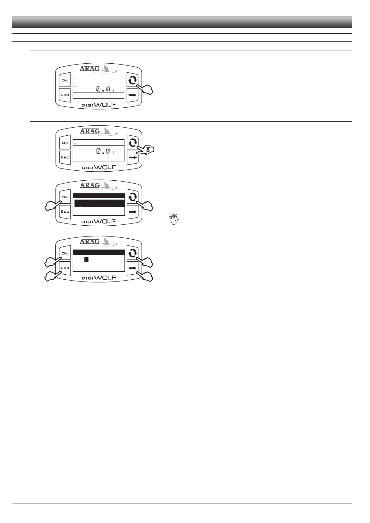
SWITCH ON
The display turns on automatically at liquid passage. If you need to switch on the
device to check or modify data, press OK.
DigiWolf switches on and displays the gure shown.
Press the key to see the succession of different values written in full (central part
of the display).
At rst device switch on, or after battery replacement, the device will briey
display its name and software version.
ACCESS TO SETUP MENU
Press the keys for 2 seconds at the same time to access setup menu.
SELECTION AND ACCESS TO MENU ITEMS
A Press in succession to move through items (the selected item is highlighted with
a black band)
B Press to access the selected item
Three dots under an item show the presence of another setup menu.
Fig. 15
MODIFYING DATA
A Press to toggle from one digit to another
B Press in succession to modify the value of the digit highlighted by the cursor
C Press to conrm the change. The display goes back to the previous screen.
D Press to exit current page without conrming changes.
8
Page 9

MENU STRUCTURE
Calibration
Man. calibration
600
Auto calibration
Par. 4.1.1
Flowrate alarms
Min flow alarm
Max flow alarm
OFF
Par. 4.2
Par. 4.2
Display
Contrast
Brightness
50%
Par. 4.3
Par. 4.3
Energy saving
Display shut-off
Backlight shut-off
15min
Par. 4.4
Par. 4.4
Options
Units of measurem.
Language
Units of measurem.
Flowrate
Volume
l/min
Units of measurem.
Volume
Flowrate
l
Par. 4.6
Par. 4.6
Test
Sensor frequency
Firmware version
0.0Hz
Battery voltage
Par. 4.6
Test
Battery voltage
Firmware version
Sensor frequency
2.98V
Par. 4.6.1
Test
Display test
Sensor frequency
Battery voltage
Par. 4.6.2
Test
Keys test
Battery voltage
Display test
Setup menu
Calibration
Flowrate alarms
Display
Setup menu
Flowrate alarms
Calibration
Display
Setup menu
Display
Calibration
Flowrate alarms
Setup menu
Energy saving
Flowrate alarms
Display
Setup menu
Options
Display
Energy saving
Setup menu
Test
Energy saving
Options
Calibration
Auto calibration
Man. calibration
Flowrate alarms
Min flow alarm
Max flow alarm
Display
Brightness
Contrast
OFF
50%
Energy saving
Backlight shut-off
Display shut-off
30s
Options
Language
Units of measurem.
English
Test
Firmware version
Sensor frequency
Battery voltage
1.00RC2
0.0 l
2
1
0.0 l/min
Switch on
2 sec.
Par. 4.1.2
SETUP
Par. 4.5.1
Par. 4.5.2.1
9
Par. 4.5.2.1
Par. 4.5.2.2
Fig. 16
Page 10

End reading
0.0 l/min
¬
¬
Calibration
67.58 l
¬
¬
C
D
067.580
o
1
2
B
A
1
2
SETUP
4 PRELIMINARY SETUP FOR USE
For a correct display of data regarding treatment, some preliminary set ups are necessary when installing DigiWolf on farming machines.
4.1 Calibration
Rate reading may not be correct due to different system congurations (tubes, valve, etc.). Therefore, we recommend to make
a spray test; in case the measured value is different from the real one, perform an automatic calibration procedure or manually
calculate owrate constant.
4.1.1 Automatic calibration
Make a quantity of liquid previously measured or that can be measured with another system go through the owmeter. The greater the amount of
liquid used to perform the calibration procedure, the more accurate the calibration.
2) Access Automatic calibration menu (Setup menu > Calibration > Auto calibration). Once inside the menu, the device is ready to start measuring without
any further controls.
Fig. 17
3) Make the liquid go through the system. The display will start to show the increasing value of the measured quantity of liquid. Once liquid passage has nished,
the value on the display will not change any more.
At this point, press OK. In the lower part of the display, the message Stabi-
lization will come up and the device will show the screen on the side.
Fig. 18
Setting of liquid amount actually passed through the owmeter during calibration procedure.
Display of liquid amount read by the owmeter during calibration procedure.
4) Using the keys, enter the values of the liquid quantity previously measured:
A) Press to toggle from one digit to another
B) Press in succession to modify the value of the digit highlighted by the cursor
C) Press to complete calibration procedure, or D) Press for 1 sec. to cancel calibration procedure.
If, after starting calibration, the device does not sense any ow passage (and the display remains in 0), press OK to exit the calibration
procedure without saving.
If the device continues to sense the liquid ow after pressing OK, after a few seconds the error message Stop flow!will be displayed.
Once the ow has been interrupted, the reading will stabilize as by standard procedure.
10
Page 11

4.1.2 Manual calibration
Calibration
Man. calibration
Auto calibration
600
Flowrate constant
Min value
Max value
C
1
50000
B
D
A
06000
APPROXIMA
TE CONST
ANT
XXX
To set the owrate constant manually, calculate and set the correct constant using the following formula:
SETUP
[amount measured by device]
[actually delivered quantity]
Fig. 19
Fig. 20
APPROXIMATE CONSTANT
XXX
x [constant indicated on flowmeter body]
1) Access Manual calibration menu (Setup menu > Calibration > Man. calibration).
In Calibration menu, selecting Manual calibration, under the item the currently set constant will be displayed.
Press OK to access value modication.
2) Using the suitable keys, set the value of the owmeter constant:
A) Press to toggle from one digit to another
B) Press in succession to modify the value of the digit highlighted by the cursor
C) Press to save changes or D) Press to exit current page without conrming
changes. Refer to the label on the body (Fig. 21).
The owmeter body must be assembled with the arrow on the label
facing the ow direction.
CODE Approximate constant
4628405 250
4628506 132
4628707 64
Tab. 3
Fig. 21
11
Page 12

Flowrate alarms
Min flow alarm
Max flow alarm
6.00/min
Min flow alarm
Min value
Max value
0.1
99999.9
OFF
o
Min flow alarm
Min value
Max value
C
0.1
99999.9
B
D
A
0040.00
l/min
o
Display
Luminosità
Contrasto
50%
Luminosità
50%
1
2
2
SETUP
4.2 Flowrate alarms
Set the minimum and maximum values beyond which the display must show an alarm message.
1) Access Flowrate alarms menu (Setup menu > Flowrate alarms).
Min. and max. owrate alarms setting is done in the same way.
Under the selected item, the currently set value will be displayed.
Press
OK to access modication of the selected item.
Fig. 22
Fig. 23
Fig. 24
4.3 Display
Adjust display brightness and contrast.
Fig. 25
2) To activate the alarm, press
and
at the same time until the message
OFF disappears and owrate alarm value is displayed.
Carry out the same procedure to deactivate owrate alarm again.
3) Set owrate alarm value:
A) Press to toggle from one digit to another
B) Press in succession to modify the value of the digit highlighted by the cursor
C) Press to save changes or D) Press to exit current page without conrming changes.
Access display menu (Setup menu > Display).
Brightness and contrast adjustment is done in the same way.
Under the selected item, the currently set value will be displayed.
Press
OK to access modication of the selected item.
Fig. 26
1) Set the value using the key . Each time it is pressed, the value will increa-
se by 10% until reaching 100%, and then starts back from 0.
2) Press OK to save, or ESC to exit without saving.
The brightness value affects battery life: the higher the value, the shorter the battery life.
12
Page 13

4.4 Energy saving
Energy saving
Backlight shut-off
Display shut-off
30s
Backlight shut-off
Min value
Max value
C
1
300
B
A
300
s
C
Options
Language
Units of measurem.
English
2
1
2
Language
Italiano
English
Español
Português
DigiWolf allows the setting of some parameters in order to prolong battery life:
- Backlight shut-off:
it is possible to set a time in seconds after which the backlight will turn off automatically if no key is pressed.
- Display shut-off:
it is possible to set a time in minutes after which the display will turn off automatically if no key is pressed and there is no liquid ow.
After switch off, the display will automatically turn on by pressing any key or when the device detects liquid ow.
1) Access energy saving menu (Setup menu > Energy saving).
Under the selected item, the currently set value will be displayed.
Press
OK to access modication of the selected item.
Fig. 27
2) Set the value:
A) Press to toggle from one digit to another
B) Press in succession to modify the value of the digit highlighted by the cursor
C) Press OK to save, or ESC to exit without saving.
Fig. 28
SETUP
4.5 Options
4.5.1 Language
Set desired language and units of measurement.
Fig. 29
Fig. 30
Access language setup menu (Setup menu > Options > Language).
Under the selected item, the currently set value will be displayed.
Press
OK to access language selection.
1) Select language using .
2) Press OK to save, or ESC to exit without saving.
13
Page 14

Units of measurem.
Flowrate
Volume
l/min
2
1
2
Flowrate
l/min.
GPM
m/h
3
Units of measurem.
Volume
Flowrate
l
2
1
2
Volume
l
gal
m
3
SETUP
4.5.2 Units of measurement
Set units of measurement for owrate values and volume read by the device.
4.5.2.1 Rate units of measurement
Fig. 31
Fig. 32
4.5.2.2 Volume units of measurement
Access instant rate units of measurement menu (Setup menu > Options > Units
of measurem. > Flowrate).
Under the selected item, the currently set value will be displayed.
Press
OK to access owrate units of measurement selection.
1) Select measurement unit using .
2) Press OK to save, or ESC to exit without saving.
Fig. 33
Fig. 34
Access volume units of measurement menu (Setup menu > Options > Units of
measurem. > Volume).
Under the selected item, the currently set value will be displayed.
Press
OK to access volume units of measurement selection.
1) Select measurement unit using .
2) Press OK to save, or ESC to exit without saving.
14
Page 15

4.6 Test
Test
Display test
Sensor frequency
Battery voltage
Test
Keys test
Battery voltage
Display test
1
2
1
1
In this menu is it possible to see some information and run a device operation test:
- Firmware version:
the display shows the rmware version installed on the device.
- Sensor frequency:
in the presence of ow passage, the display shows in real time the frequency of the signal from the sensor reading the owrate.
- Battery voltage:
the display shows the voltage level of the batteries in the device.
4.6.1 Display test
Display test checks the correct operation of the display on the device.
Access display test menu (Setup menu > Test > Display test).
Press
OK.
Fig. 35
The display shows all pixels on.
Press
ESC to return to the previous screen.
SETUP
Fig. 36
4.6.2 Keys test
Keys test checks the correct operation of the keys on the device.
Fig. 37
Fig. 38
Access keys test menu (Setup menu > Test > Keys test).
Press
OK to access the test.
1) Pressing one key, the corresponding portion of the display will light up.
2) To exit, press
ESC: after lighting up the corresponding portion of the display, it
will return to the previous screen.
15
Page 16

1
0.0 l
2
1
0.0 l/min
6.23 l
2
1
21.84 l/min
6.23
6.23 l
2
1
21.84 l/min
6.23
6.23 l
2
1
21.84 l/min
0.00
50.00 l
2
1
21.84 l/min
999.99
1050.0 l
2
1
21.84 l/min
1000.0
10049 l
2
1
21.84 l/min
9999.9
10050 l
2
1
21.84 l/min
10000
...
SETUP
5 USE
Once the setup is nished, Digiwolf is ready for use. The main screen shows the display divided into three horizontal sectors.
The sectors showing the symbols
The third data represents instant rate value.
Fig. 39
Fig. 40
5.1 Partial totalizer reset
and 2 represent the partial totalizers, individually resettable.
Partial totalizers
Instantaneous rate
Feed some liquid to the system. The display will start to show the increasing value
of the measured quantity of liquid, and the instant rate value.
To reset a totalizer, it is necessary to visualize it in full.
To do this, press the button several times until the value to zero is in the central
area of the display.
Fig. 41
Press ESC for two seconds. The totalizer will zero.
Fig. 42
- Do not place DigiWolf under pressurized water.
- Use the owmeter only within recommended rate range (Tab. 2 - Par. 2.3.1). Beyond these limits, the ow-meter may give out incorrect data.
- To avoid damaging the owmeter, do not exceed the maximum rate except for short periods.
ARAG can not be held responsible for damage caused to persons, animals or things from the incorrect or unintended use of Digiwolf or
its parts.
- Do not exceed the max. operation pressure (Tab. 2 - Par. 2.3.1).
Display of the symbol ------ shows that the rate or the totalizer are over the max. displayable value.
Totalizers have oating points and display a max. of 5 gures. Up to 999.99 two decimals are shown, it then drops to 1 and 0 with the transition to thousands and tens of thousands (Fig. 43).
16
Fig. 43
Page 17

MAINTENANCE
6 CLEANING AND REPAIR
- At the end of each treatment, run clean water through the tubes.
- If necessary, periodically clean or replace the owmeter paddle (Par. 6.2). Periodically clean the paddle anyway.
Do not use metal or abrasive objects to clean the paddle.
Do not use solvents or fuel to clean the case outer surface.
CAUTION:
Before each of the following operations, use the following precautions:
1) Wear gloves, goggles and protective clothing.
2) Stop the machine and disconnect the power of the system.
3) Make sure that the system is no longer under pressure.
When replacing the sensor or the paddle, check for the correct reading of the owmeter. Proceed to a new calibration if necessary.
6.1 Troubleshooting
FAULT CAUSE REMEDY
The display is off No power supply
Rate is beyond operation limits
of the owmeter
Totalizers do not progress
during the passage of liquid.
Displayed owrate is not
stable
The sensor is not connected
correctly
The paddle-wheel is locked
Presence of turbulence or air in
the circuit
Worn paddle • Replace the paddle.
• Check for the batteries and their
correct positioning.
Replace them when necessary.
• The model of the owmeter is
not adequate for the owrate to be
measured.
Replace the owmeter.
• Check the sensor connection.
• Clean or replace the paddle-
wheel group if necessary.
• Check the circuit.
Tab. 4
17
Page 18

APPROXIMA
TE CONST
ANT
XXX
MAINTENANCE
6.2 Paddle cleaning and replacement
lock
unlock
Fig. 43 Fig. 44 Fig. 45
1) Remove the fork from the monitor using a screwdriver.
2) Remove the monitor from the owmeter body.
3) Unscrew the ring nut in a counter clockwise direction and remove the sensor housing block from the owmeter body.
4) With half a rotation, remove the paddle group from the sensor housing block in a counter clockwise direction.
5) Immerse the paddle group in detergent liquid for several hours.
6) Wash the paddle group thoroughly with running water and check its correct operation. If necessary, replace the complete paddle group with its
suitable spare part (code 4626000.500).
7) Ret the paddle group on the electronic sensor with a clockwise rotation until it clicks in place.
2
1
Arrows direction on the body must
correspond to the one on the label
Fig. 46
8) Ret the sensor housing block on the owmeter body tightening the ring nut in a clockwise direction until it stops paying attention to keep the
arrow on the coupling facing the ow direction.
18
Page 19

6.3 OR replacement
With the removed sensor housing block (see Par. 6.2) proceed as follows:
1) Remove the fork from the ring nut using a screwdriver.
Fig. 47
2) Remove the ring nut.
- OR replacement:
Replace the ORs (code G10051V - ARAG spare parts catalogue).
3) Ret the sensor housing block ensuring that the fork is correctly inserted in the ring nut.
Fig. 48
MAINTENANCE
19
Page 20

TECHNICAL DATA
Data Min. Max. Default UoM Notes
Calibration Manual calibration 1 50,000 600 -- --
Min. owrate alarm 0.1 99999.9 OFF l/min.
Flowrate alarms
Max. owrate alarm 0.1 999999.9 OFF l/min.
Brightness 0% 100% 50% % --
Display
Contrast 0% 100% 50% % --
Backlight
Energy
saving
shut-off
Display
shut-off
Language - - English -
Options
Rate units of
measurement
Volume units of
measurement
7 TECHNICAL DATA
Description DigiWolf
Power supply 2 AA batteries type LR6 (alkaline) or FR6 (Li-Fe S2)
Max. absorption
Working temperature
Storage temperature
Weight (without batteries) 680 ÷ 750 g (depending on the type)
The alarm can be deactivated
setting the value "OFF"
The alarm can be deactivated
setting the value "OFF"
1 sec. 300 sec. 30 sec. sec.
1 min. 120 min. 15 min. min.
Language settings: Italiano, English, Español,
Português, Français, Deutsch, Cesky, Polski,
, Русский, Magyar.
ニホン
- - l/min. -
Units of measurement settings: l/min, GPM,
3
m
/h
- - litres - Units of measurement settings: l, gal, m
40 mA (100% backlight)
4.7uA (standby)
0 °C ÷ 50 °C
+32 °F ÷ +122 °F
0 °C ÷ 50 °C / +32 °F ÷ +122 °F (inserted batteries)
-30 °C ÷ 80 °C / -22 °F ÷ +176 °F (without batteries)
Tab. 6
3
Tab. 5
8 DISPOSAL AT THE END OF SERVICE
Dispose of the system in compliance with the established legislation in the country of use.
20
Page 21

Notes
21
Page 22

9 GUARANTEE TERMS
1. ARAG s.r.l. guarantees this apparatus for a period of 360 day (1 year) from the date of sale to the client user (date of the
goods delivery note).
The components of the apparatus, that in the unappealable opinion of ARAG are faulty due to an original defect in the
material or production process, will be repaired or replaced free of charge at the nearest Assistance Centre operating
at the moment the request for intervention is made. The following costs are excluded:
- disassembly and reassembly of the apparatus from the original system;
- transport of the apparatus to the Assistance Centre.
2. The following are not covered by the guarantee:
- damage caused by transport (scratches, dints and similar);
- damage due to incorrect installation or to faults originating from insufficient or inadequate characteristics of the electrical system, or to alterations resulting from environmental, climatic or other conditions;
- damage due to the use of unsuitable chemical products, for spraying, watering, weedkilling or any other crop treatment, that may damage the apparatus;
- malfunctioning caused by negligence, mishandling, lack of know how, repairs or modications carried out by unauthorised personnel;
- incorrect installation and regulation;
- damage or malfunction caused by the lack of ordinary maintenance, such as cleaning of lters, nozzles, etc.;
- anything that can be considered to be normal wear and tear.
3. Repairing the apparatus will be carried out within time limits compatible with the organisational needs of the Assistance Centre.
No guarantee conditions will be recognised for those units or components that have not been previously washed and
cleaned to remove residue of the products used.
4. Repairs carried out under guarantee are guaranteed for one year (360 days) from the replacement or repair date.
5. ARAG will not recognise any further expressed or intended guarantees, apart from those listed here.
No representative or retailer is authorised to take on any other responsibility relative to ARAG products.
The period of the guarantees recognised by law, including the commercial guarantees and allowances for special pur-
poses are limited, in length of time, to the validities given here. In no case will ARAG recognise loss of prots, either
direct, indirect, special or subsequent to any damage.
6. The parts replaced under guarantee remain the property of ARAG.
7. All safety information present in the sales documents regarding limits in use, performance and product characteristics
must be transferred to the end user as a responsibility of the purchaser.
8. Any controversy must be presented to the Reggio Emilia Law Court.
Page 23

Conformity Declaration
ARAG s.r.l.
Via Palladio, 5/A
42048 Rubiera (RE) - Italy
P.IVA 01801480359
Dichiara
che il prodotto
descrizione: Flussometro a palette
modello: DigiWolf
serie: 4627xxx, 4628xxx
risponde ai requisiti di conformità contemplati nella seguente Direttiva Europea:
2004/108/CE e successive modificazioni
(Compatibilità Elettromagnetica)
Riferimenti alle Norme Applicate:
EN ISO 14982
(Macchine agricole e forestali - Compatibilità elettromagnetica
Metodi di prova e criteri di accettazione)
CEI EN 61326-1:2007
(Apparecchi elettrici di misura, controllo e laboratorio, Prescrizioni di
compatibilità elettromagnetica - Parte 1 : Prescrizioni generali)
Rubiera, 08 Marzo 2011
Giovanni Montorsi
(Presidente)
Page 24

Only use original ARAG accessories and spare parts, to maintain safety conditions foreseen by the constructor. Always refer
to the ARAG spare parts catalogue.
42048 RUBIERA (Reggio Emilia) - ITALY
Via Palladio, 5/A
Tel. +39 0522 622011
Fax +39 0522 628944
http://www.aragnet.com
info@aragnet.com
D20246_GB-m01 06/2011
 Loading...