

Page 1

BRAVO 13X SERIES COMPUTERS
46713X01
Software rel. 2.1
USE AND MAINTENANCE
Page 2

•LEGENDSYMBOLS
= Generic danger
= Burn danger
= Warning
This manual is an integral part of the equipment to which it refers and must accompany the equipment in
case of sale or change of ownership. Keep it for future reference; ARAG reserves the right to modify the
specications and instructions regarding the product at any time and without prior notice.
2
Page 3

CONTENTS
• Legend symbols ............................................................................................................................ 2
1 Product description ...................................................................................................................... 5
1.1 Intended use ......................................................................................................................... 5
2 Contents of the packaging.......................................................................................................... 5
3 Control panel .................................................................................................................................. 6
3.1 Control panel ......................................................................................................................... 6
3.2 Display (in the example, the Spraying menu) ............................................................... 6
3.3 Control panel legend (Fig. 2) .............................................................................................. 7
3.4 Display legend (the example shows Spraying menu, Fig. 3) ..................................... 7
4 Product function ............................................................................................................................ 8
5 Installation ....................................................................................................................................... 8
5.1 Precautions ............................................................................................................................ 8
6 Start up ............................................................................................................................................. 8
7 Menus structure ............................................................................................................................. 9
8 Setting preliminary to use ......................................................................................................... 10
8.1 User menu ........................................................................................................................... 10
8.1.1 Wheel type ..........................................................................................................................11
8.1.2 Wheel Constant...................................................................................................................11
8.1.3 Product density ................................................................................................................. 13
8.1.4 Row distance ..................................................................................................................... 13
8.1.5 Canopy width ..................................................................................................................... 14
8.2 Treatment menu .................................................................................................................. 15
8.2.1 Tank filling ........................................................................................................................... 15
8.2.2 Setting the field number.................................................................................................... 16
8.2.3 Resetting the "field" counters .......................................................................................... 16
8.2.4 Row type ............................................................................................................................ 17
8.2.5 Canopy type ...................................................................................................................... 17
8.3 Spraying menu .................................................................................................................... 18
8.3.1 Speed ................................................................................................................................. 18
8.3.2 Pressure ............................................................................................................................. 18
8.3.3 Flow rate ............................................................................................................................ 19
8.3.4 Battery voltage ................................................................................................................... 19
8.3.5 Surface area ...................................................................................................................... 19
8.3.6 Liquid sprayed ................................................................................................................... 19
8.3.7 Tank level ............................................................................................................................ 19
8.3.8 Distance ............................................................................................................................. 19
8.3.9 Trees treated ...................................................................................................................... 20
8.3.10 Automatic ........................................................................................................................... 20
9 Use ................................................................................................................................................... 21
9.1 Automatic operating mode ................................................................................................ 22
9.1.1 Two-sensor configurations ................................................................................................ 23
9.1.2 Four-sensor configuration ................................................................................................. 24
9.2 Manual operating mode .................................................................................................... 25
9.3 Semi-automatic operating mode ..................................................................................... 25
9.4 Operating errors ................................................................................................................. 25
3
Page 4

10 Maintenance / diagnostics / repairs ....................................................................................... 26
10.1 Troubleshooting .................................................................................................................. 26
10.2 Check the parameter "1/0 Error" .....................................................................................27
10.2.1 Absence of errors (screen "a") ........................................................................................ 27
10.2.2 Programming error (screen "b") ...................................................................................... 27
11 Technical data .............................................................................................................................. 28
11.1 Units of measurement ....................................................................................................... 28
11.1.1 Spraying menu .................................................................................................................. 28
11.1.2 Treatment menu ................................................................................................................. 28
11.1.3 User menu .......................................................................................................................... 28
11.2 Technical characteristics ................................................................................................... 29
12 Index of functions ....................................................................................................................... 29
13 Disposal at the end of service ................................................................................................. 29
14 Guarantee terms ..........................................................................................................................30
4
Page 5
1 PRODUCT DESCRIPTION
Bravo 13X is an atomizer computer specically designed for treating leafy trees, equipped with
numerous control functions that can be activated from the driver’s cabin.
The computer controls the opening and closing of the section valves on a suitable control unit
(not supplied) in automatic, semi-automatic or manual mode, detecting the presence of a tree to
be treated by means of one or two pairs of ultrasound sensors: in this way, Bravo13X allows only
spraying in the presence of plants and not in the gaps.
1.1 Intended use
Device designed for installation on agricultural machinery used for weed-killing and
spraying.
The device is designed and carried out in conformity with directive 2004/108/CE and
subsequent modications, and the EN ISO 14982 standard.
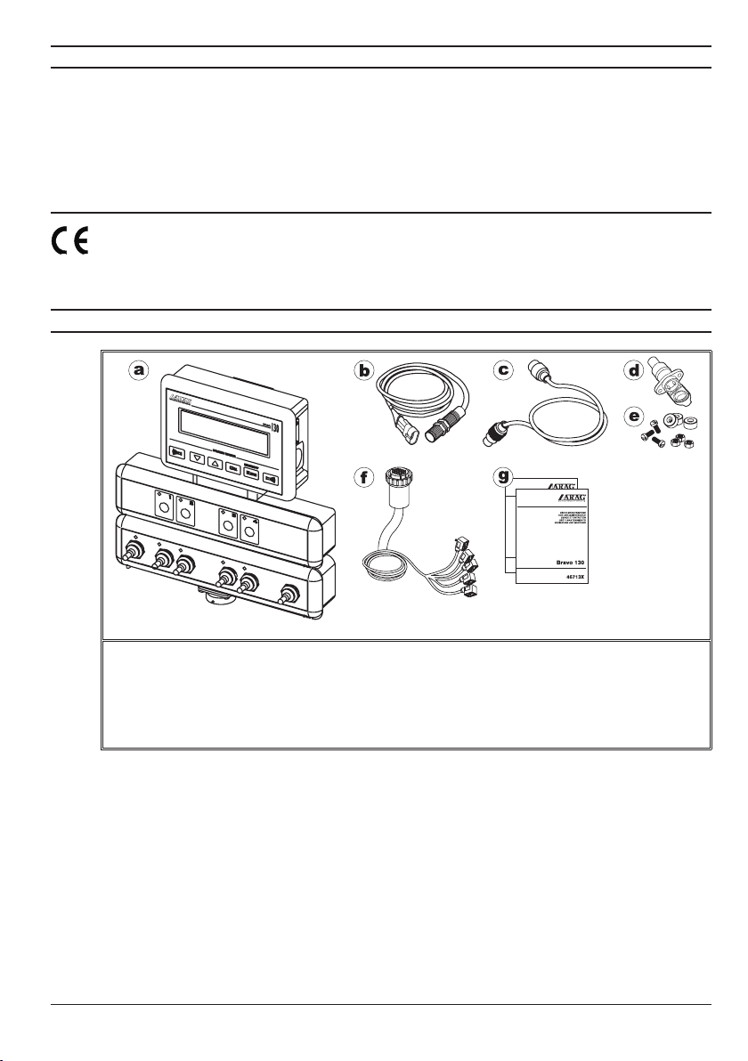
2 CONTENTS OF THE PACKAGING
Fi g. 1
a•Bravo13X
b•Speedsensor
c•Powersupplycable
d•Threepolesocketforpower
e•Magnetsandfasteningscrews
f •Cablingforconnectingtothevalves
g•InstructionManuals
5
Page 6
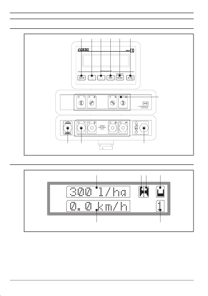
3 CONTROL PANEL
3.1 Control panel
Fi g. 2
I
L
BA C
H FG
E
D
3.2 Display (in the example, the Spraying menu)
R P OQ
Fi g. 3
M N
6
Page 7

3.3 Control panel legend (Fig. 2)
A = Control deviator for the drain valve
•Toopenthedrain valve, move the deviator downward (LED off).
•Toclosethedrain valve, move the deviator upward (LED on).
B = Control deviators for the section valves
(the number of deviators coincides with the number of section valves mounted on the system)
•Toopenthesectionvalve,movethecorrespondingdeviatorupward(LEDon).
•Toclosethedrain valve, move the corresponding deviator downward (LED off).
The section valve control varies depending on the type of function enabled in the computer.
Refer to paragraph 8.3.10 - Automatic and chapter 9 - Use.
C = Deviator for controlling the pressure control valve
•Toincreasethequantityofliquidtodistribute,pressthedeviatorupward.
•Todecreasethequantityofliquidtodistribute,pressthedeviatordownward.
When you release the deviator, the lever automatically returns to the center without making any
further changes to the quantity of liquid to be distributed.
D = The control status indicators of the section valves
(the number of LEDs coincides with the number of section valves mounted on the system)
•LEDon:thesectionvalveisopen.
•LEDoff:thesectionvalveisclosed.
E = Activation of sensors on the right side of the tractor.
F = ON/OFF button: turns the computer on/off.
ESC button: exits from the current menu during use of the Bravo 13X.
If the changed data has not been conrmed, pressing this key you exit the
current menu without making any changes.
G = Conrmation key
During the use of the Bravo 13X, this key conrms access to the selected menu or the value of the
parameter previously changed.
H = Data selection key: scrolls through the data, passing to the next eld.
Parameter change key: increases the value of a parameter.
I = Data selection key: scrolls through the data, passing to the previous eld.
Parameter change key: decreases the value of a parameter.
When changing parameters, pressing the or keys for more than three
seconds allows rapidly changing the values to be entered.
L = Activation of the sensors on the left side of the tractor
3.4 Display legend (the example shows Spraying menu, Fig. 3)
M = Second line value: the value selected is displayed (in the example, the tractor’s
instantaneous speed).
N = Number of the eld being treated
O = Tank: a ashing symbol means the reserve value has been reached.
P = Right sensor activated: indicates that the sensor, or sensors, on the right side
of the tractor have been activated; for the 4-sensor model, the symbol remains lit
independently of the number of sensors active.
Q = Left sensor activated: indicates that the sensor, or sensors, on the left side of
the tractor have been activated; for the 4-sensor model, the symbol remains lit independently of the number of sensors active.
R = First line value: the value pre-set during the installation of the computer (in the
example, instantaneous distribution).
7
Page 8

4 PRODUCT FUNCTION
Bravo 13X is an atomizer computer specically designed for treating leafy trees, equipped with
numerous control and display functions that can be activated from the driver’s cabin:
• Speed of the vehicle;
• Quantity of liquid distributed on the eld;
• Flow rate;
• Surface area treated (4 partials*);
• Distance traveled (4 partials*);
• Number of trees treated (4 partials*);
• Quantity of liquid sprayed (function equipped with 4 partials*, only enabled in the presence
of a owmeter in the system);
• Level of the tank (function only enabled in the presence of a owmeter in the system);
• Battery voltage;
• Pressure (function enabled only in the presence of a pressure transducer in the system).
The BRAVO 13X main operating principle that differentiates it from other BRAVO family computers
is the possibility of identifying the presence of plants on the sides of the tractor through the use of
ultrasound sensors and, thus, of only spraying plants and avoiding the waste of chemicals.
The BRAVO 132 must be equipped with two ultrasound sensors (mounted at the sides of the tractor)
to trip the control unit valves (t wo section valves, one pressure control valve and one drain valve)
and increase/decrease the sprayer delivery.
The model BRAVO 134 can be equipped with four sensors to detect trees of different heights and to
spray only where needed. BRAVO 134 can be connected to control units consisting of four section
valves, a pressure control valve and a drain valve.
* By partial we mean a memory area containing data relative to a parameter previously set and stored, which can be recalled at the time of use.
5 INSTALLATION
Installation, connection and start-up of the computer, unit and sensors connected to it must be
performed by specialized personnel.
All the information regarding installation and preliminary programming is described
in the installation manual provided to specialized installers.
ARAG is not responsible for damage to equipment, persons, animals or crops caused
by a faulty installation or one performed by non-specialized or unprepared personnel.
In the event of damage to the computer or the equipment and sensors connected to
it, caused by any of the above, the warranty will automatically be considered void.
5.1 Precautions
• Never expose the equipment to water jets.
• Never use solvents or petrol to clean the external parts of the container.
• Do NOT use direct jets of water for cleaning the display.
• Comply with the specic power supply voltage (12 Vdc).
• In case of electric arc welding, make sure that the power supply to the device is
disconnected; if necessary, disconnect the power supply cables.
• Use only original ARAG spare parts or accessories.
6 START UP
Before turning it on, make sure the drain valve is CLOSED.
To close the drain valve, push the deviator, A (Fig. 2) upwards.
To turn on the device, press the key.
When the device is turned on it rst performs a diagnostic test of the display.
Then it displays the version of the software and automatically goes to the Spraying menu
(Fig. 4), from which you can access all the functions provided by the computer.
8
Page 9
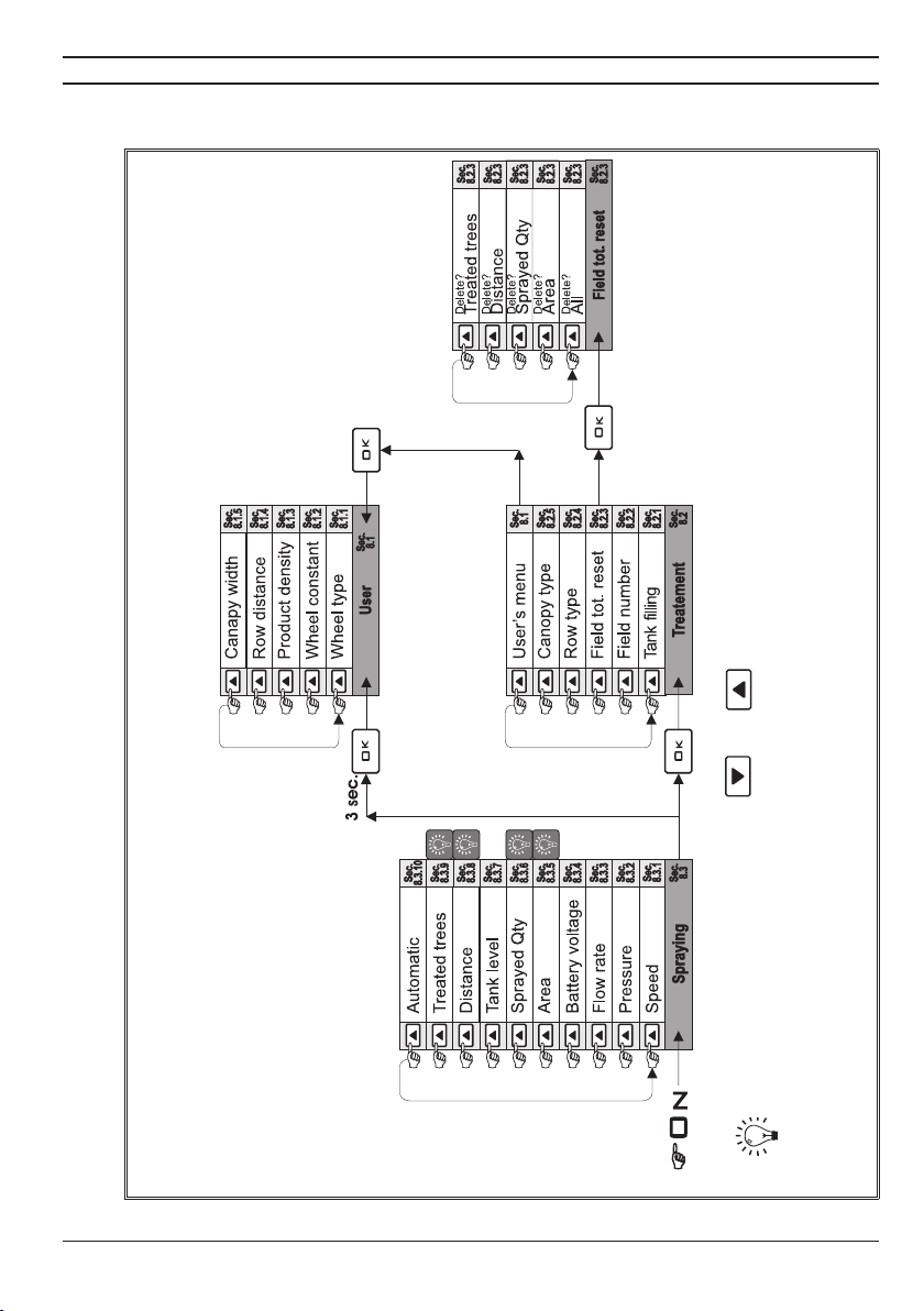
7 MENUS STRUCTURE
From the Spraying menu it is possible to access all the functions of the Bravo13X.
These functions are shown in Fig. 4, which illustrates the menu structure.
Fi g. 4
QUICK ACCESS: by pressing the and keys at the same time you can
reset the corresponding value.
9
Page 10
8 SETTING PRELIMINARY TO USE
It is necessary to set several parameters before beginning a treatment in order to
perform it correctly. Set all the functions on the following menus:
•User menu (par. 8.1)
•Treatment menu (par. 8.2)
For any questions regarding the conguration of these menus, consult sec.
7 - Menus structure.
8.1 User menu
To access the User menu, proceed as follows:
1) Turn on the device by pressing and holding the key; upon start-up, Bravo 13X performs the
self-diagnostics as indicated in sec. 6 - Start-up, then automatically enters the Spraying menu.
2) From any Spraying menu function, you can press the key to enter the
Treatment menu;
3) Now scroll through the functions of the Treatment menu:
3a) To go to the next function, press the key.
3b) To return to the previous function, press the key.
4) When the entry User menu appears, press the key;
Quick access: you can access the user menu directly from any function of the
spraying menu by pressing the key for at least three seconds.
Scroll through the entries by pressing the and keys and select the function you wish
to set by pressing the key.
The following functions will appear in succession:
•Wheel type (see sec. 8.1.1)
•Wheel constant (see sec. 8.1.2)
•Product density (see sec. 8.1.3)
•Row distance (see sec. 8.1.4)
• Canopy width (see sec. 8.1.5)
6) To exit from the User menu, press the key (return to the previous menu:
Spraying menu or Treatment menu depending on the selection method used).
For any questions regarding the method of selecting these functions, consult
sec. 7 - Menus structure.
10
Page 11

8.1.1 Wheel type
The “WHEEL TYPE” function allows programming and, thus, recalling with a single key, the parame-
ters relative to different types of wheels (such as: if they are replaced for different types of crops or if
the computer is moved from one agricultural machine to another). This function recalls a parameter, the
“WHEEL CONSTANT”, which must be entered as indicated in paragraph 8.1.2 - Wheel constant.
Up to 5 types of wheels can be programmed. These are recalled for use by the procedure described below.
1) Scroll through the functions on the User menu using the and keys and select the
entry “Wheel type”, followed by a number that indicates the active wheel.
2) Conrm the selection by pressing the key: the number that indicates the wheel type will
ash on the display.
3) Change the value using the and keys.
4) Conrm the value set by pressing the key.
8.1.2 Wheel Constant
As the tractor moves forward, the Bravo 13X computer receives signals from the speed sensor
installed on one of the wheels. This data is processed on the basis of a value called the “WHEEL
CONSTANT” that must be entered manually or through the automatic insertion function.
The wheel constant set represents the value of the constant relative to the wheel
type currently selected: for example, to change the wheel constant that corresponds
to wheel type 2, you must rst set the type for wheel 2 following the method shown
in paragraph 8.1.1 - Wheel type.
1) Scroll through the functions on the User menu using the and keys and select the
entry “WHEEL CONSTANT”, followed by the active value.
2) Conrm the selection by pressing the key: the active setting method appears on the display.
• MANUAL SETTING
To perform the setting using this method, you manually enter the value of the constant after having
previously calculated it.
The wheel constant can be calculated using the distance that the wheel on which the sensor
is installed travels in 10 revolutions (a value to be calculated with the tires inated to working
pressure).
The formula for calculating the wheel constant is:
Distance traveled (m) x 10
= ——————————————————
number of magnets
Example:
- Distance traveled in 10 revolutions of the wheel 25,4 m
- Number of magnets installed: 10
The wheel constant is:
25,4 x 10
= ————————————— = 25,4
10
1) Select the Manual setup mode by scrolling the Wheel Constant Menu with the and
keys;
2) Conrm the selection by pressing the key.
3) Change the value using the and keys.
4) Conrm the value set by pressing the key.
CONTINUES
11
Page 12

• AUTOMATIC CALCULATION
BRAVO 13X is able to calculate the wheel constant automatically by using the number of impulses
sent by the speed sensor in a straight line of:
- 100 m (EU)
- 300 yards (US)
1) Fill the tank 50% full.
2) Position the tractor at the beginning of the path.
3) Select Automatic calc. by scrolling the Wheel constant menu using the and
keys; Conrm the selection by pressing the key.
4) Start and follow the path.
5) At the end of the path, stop and press the key: BRAVO13X will automatically calculate the
wheel constant and display it.
- If the number of impulses received by the computer during automatic calibra-
tion is too low to calculate the wheel constant, the following message displays:
.
In this case, check the installation of the sensor and repeat the procedure.
An error can also occur if the wheel has been replaced incorrectly or if the sensor is
too far from the magnet.
If the problem persists after you have veried that everything is mounted correctly,
contact the installer.
- The test must be performed on medium hard ground.
If distribution is carried out on very soft or very hard ground, the difference in rolling
diameter could cause an error in the distribution calculation.
In this case, it is advisable to repeat the procedure.
End of the wheel constant setting procedure
12
Page 13

8.1.3 Product density
The quantity of the products sprayed can vary according to their density.
For this reason, the computer allows you to enter a density factor and, thus, to calculate the quantity
of liquid effectively sprayed.
This value is very important because, if mechanical palette or turbine owmeters are used, since
these are affected by variations in the density of the liquid, it could happen that the liquid will be
sprayed in a different quantity than that set and measured by the computer.
The preset density factor is “1” and it refers to water or, at any rate, a liquid having the same
density as water.
Since it would be impossible to provide a table with density data for all products that can be sprayed,
it is up to the user to evaluate any correction to the entered value that will allow the computer the
possibility to exactly indicate the quantity dispensed:
- if, at the end of spraying, the tank still contains liquid, the density factor must be decreased;
- if, on the other hand, the liquid is nished before the end of distribution, the factor must be increased.
An electromagnetic owmeter such as the ORION series 462XXX is not affected by
the difference in liquid density: for this reason, if this owmeter is present in your
system, set the density factor to 1,00.
1) Scroll through the functions on the User menu using the and keys and select the
entry “PRODUCT DENSITY”, followed by a number that indicates the value set.
2) Conrm the selection by pressing the key: in this way, the number that indicates the density
factor will ash on the display.
3) Change the value on the display by using the and keys.
4) Conrm the value set by pressing the key.
8.1.4 Row distance
The “ROW DISTANCE” function allows programming and recalling with a single key all the para-
meters relative to the distances between the rows of trees to be treated, so as to correctly calculate
the surface area treated and the volume of liquid sprayed in
liters/hectare.
Up to 5 types of rows can be programmed: to perform the setting, follow the procedure shown
below:
1) Scroll through the functions on the User menu using the and keys and select the
entry “ROW DISTANCE”.
2) Conrm the selection by pressing the key.
The following information will appear on the display:
AB
A•thetype of row active, indicated by a number
from 1 to 5;
B•thevalueofthedistance between rows.
Fi g. 5
3) Select the type of row you wish to set by scrolling to the A value using the and keys;
while scrolling, the display will show the distance between rows (B) corresponding to the type of
row activated.
4) Conrm the selection by pressing the key: in this way, the number that indicates the distance
between rows (B) will ash on the display.
5) Change the value B on the display by using the and keys.
6) Conrm the value set by pressing the key.
ARAG code 46713000.100 ultrasound sensors detect the presence of the plant up to
a distance of 6 m.
13
Page 14

8.1.5 Canopy width
Depending on how the ultrasound sensors are mounted to the tank or tractor, they will detect either the
trunk of the tree or its canopy.
The value to be entered in the computer is the
“CANOPY WIDTH”.
If the sensors are oriented towards the canopy,
set it to “0”;
if the sensors are oriented towards the trunk, the computer must be told how wide the canopy is to open the
valves at the correct point for effective spraying.
This is done with the following calculation:
width of the canopy in meters (CW) less the diameter of the trunk in meters (DT), divided by two:
Fi g. 6
LC – DT
—————
2
Therefore, in case of trees with an average width of 40 cm by the trunk and 3 m by the canopy, the
value to be entered is 1,3 m (Fig. 6):
3 - 0,4
= 1,3 m
2
If, on the other hand, the sensors are detecting the canopy and not the trunk, the value to enter will
be 0 so that when the canopy is detected, the computer will immediately begin treatment.
It is possible to program this function with up to 5 different types of canopy.
To enter the data, follow the procedure shown below:
1) Scroll through the functions on the User menu using the and keys and select the
entry “Canopy WIDTH”.
2) Conrm the selection by pressing the key.
The following information will appear on the display:
B A
Fi g. 7
A•thetype of canopy active, indicated by a
variable, progressive number up to 5;
B•thewidth value for the canopy.
Select the type of canopy you wish to set by scrolling the A value using the and keys;
while scrolling the A value, the display will show the width of the canopy (B) corresponding to the
type of canopy selected.
4) Conrm the selection by pressing the key: in this way, the number that indicates the width
of the canopy (B) will ash on the display.
5) Change the value B on the display by using the and keys .
6) Conrm the value set by pressing the key.
14
Page 15

8.2 Treatment menu
Before each new spraying, perform the preliminary operations gathered together in the Treatment
menu; to access the menu, proceed as follows:
1) Turn on the device by pressing and holding the key; upon start-up, Bravo 13X performs the
self-diagnostics as indicated in sec. 6 - Start up, then automatically enters the Spraying menu.
2) From any function of the Spraying menu, press the key;
3) Scroll through the entries in the Treatment menu by pressing the and keys and
select the function you wish to set by pressing the key.
The following functions will appear in succession:
• Tank lling (see sec. 8.2.1)
• Field Number (see sec. 8.2.2)
• Total Field Reset (see sec. 8.2.3)
• Row Type (see sec. 8.2.4)
• Canopy Type (see sec. 8.2.5)
• User menu (see sec. 8.1)
4) To exit from the Treatment menu, press the key (return to the Spraying menu).
For any questions regarding the method of selecting these functions, consult sec.
7 - Menus structure.
All the entries of the User menu are described in section 8.1 - User menu.
8.2.1 Tank lling
The "TANK FILLING" function allows setting the quantity of liquid in the tank and, thus, calculating
the liquid remaining at the end of treatment (starting from the ll value, BRAVO 13X takes away
the quantity of liquid sprayed).
The computer also signals when the reserve level is reached with a buzzer and ashing indicator
on the display.
The liquid loaded in the tank can be set by following the procedure described below:
1) Scroll through the functions on the Treatment menu using the and keys and select
the entry "TANK FILLING", followed by a number that indicates the quantity of liquid remaining in
the tank.
2) Conrm the selection by pressing : the display will ash the maximum tank lling quantity.
3) To modify this value, use the and keys.
4) Conrm the value set by pressing the key.
CONTINUES
15
Page 16

8.2.2 Setting the eld number
When a cultivation is being treated, BRAVO 13X keeps the following data in memory:
• Surface area treated
• Liquid distributed
• Distance traveled
• Number of trees treated
The four values grouped together relative to a specic treatment are called a "FIELD". It is possible
to store four different cultivations.
The "FIELD NUMBER" function allows choosing the number of the eld in which to store the data
relative to the cultivation that you are getting ready to treat, before the treatment.
To set the eld number, follow the procedure shown below:
1) Scroll through the functions on the Treatment menu using the and keys and select
the entry "FIELD NUMBER", followed by a number that indicates the active eld.
2) Conrm the selection by pressing the key: the number that indicates the eld will ash
on the display.
3) Change the value using the and keys.
4) Conrm the value set by pressing the key.
To read the cultivation data stored in a certain eld, consult the Spraying menu
(sec. 8.3 - Spraying menu).
8.2.3 Resetting the "eld" counters
Before beginning a new treatment, BRAVO 13X allows you to reset all, or only some, of the data
contained in the active "FIELD".
Before erasing the data, select the number of the eld in which you wish to record
the data relative to the new treatment. For any questions regarding the method of
eld selection refer to section 8.2.2 - Setting the eld number.
To reset the data, follow the procedure described below:
1) Scroll through the functions on the Treatment menu using the and keys and select
the entry "TOTAL FIELD RESET".
2) Conrm the selection by pressing the key.
3) Scroll through the "TOTAL FIELD RESET" function using the and keys and select
the parameter that you wish to reset; as you scroll through the display, the request to delete the
following data, will appear, in succession, as shown in F i g . 8 :
A
Fi g. 8
• All (allows resetting all the parameters at the
same time)
• Surface area
• Liquid sprayed
• Distance
• Trees treated
During this operation, the number of the active eld (A) appears on the display.
4) Conrm the deletion of the selected data by pressing the key.
End of the section on "Resetting the "eld" counters"
16
Page 17

8.2.4 Row type
The "ROW TYPE" function allows recalling, with a single key, all the parameters relative to the
distances between the rows of trees to be treated, that were previously programmed using the
"ROW DISTANCE" function (as described in section 8.1.4 - Row distance).
To select the type of row on which to perform the treatment, proceed as follows:
1) Scroll through the functions on the Treatment menu using the and keys and select
the entry "ROW TYPE", followed by a number that indicates the active row number.
The following information will appear on the display:
A B
Fi g. 9
A•thetype of row active, indicated by a progres-
sive number from 1 to 5;
B•thevalueofthedistance between rows,
relative to the row selected.
2) Conrm the selection by pressing the key: the number that indicates the row (A) will ash
on the display.
3) Change the value using the and keys.
4) Conrm the value by pressing the key.
8.2.5 Canopy type
The "CANOPY TYPE" function allows selecting and, thus, recalling, with a single key, all the pa-
rameters relative to the canopy of the trees to be treated, that were previously programmed using
the "CANOPY WIDTH" function (as described in section 8.1.5 - Canopy width).
To select the type of canopy on which to perform the treatment, proceed as follows:
1) Scroll through the functions on the Treatment menu using the and keys and select
the entry "CANOPY TYPE", followed by a number that indicates the active canopy number.
The following information will appear on the display:
A B
Fi g. 10
A•thetype of canopy active, indicated by a
progressive number from 1 to 5;
B•the width value for the selected canopy.
2) Conrm the selection by pressing the key: the number that indicates the type of canopy
(A) will ash on the display.
3) Change the value using the and keys.
4) Conrm the value by pressing the key.
17
Page 18

8.3 Spraying menu
During the treatment BRAVO 13X displays the value of the liquid that is being sprayed together with
other data, selectable using the functions of the Spraying menu, which are shown below:
•Speed(seesec.8.3.1)
•Pressure(seesec.8.3.2)
•Flowrate(seesec.8.3.3)
•Batteryvoltage(seesec.8.3.4)
•Surfacearea(seesec.8.3.5)
•Liquiddistributed(seesec.8.3.6)
•Tanklevel(seesec.8.3.7)
•Distance(seesec.8.3.8)
•Treestreated(seesec.8.3.9)
•Automatic(seesec.8.3.10)
1) Turn on the device by pressing the key.
Bravo 13X will perform the self-diagnostics as indicated in sec. 6 - Start-up, then automatically
enter the Spraying menu.
2) Now you can scroll through the functions using the and keys.
The following information will appear on the display:
CA B
Fi g. 11
A•thevalueofinstantaneous distribution;
B•thevaluerelativetothefunction selected
(in the example, the speed);
C•thenumber of the active eld.
Parameter “A” depends on the programming done at installation; Bravo 13X displays the volume
of liquid delivered per unit surface, the operating pressure, the treatment speed (updated every
ve seconds), or the volume of liquid delivered per tree (updated every ve trees).
For any questions regarding the conguration of these menus, consult
sec. 7 - Menus structure.
8.3.1 Speed
Through this function, BRAVO 13X displays the vehicle's instantaneous speed.
QUICK ACCESS: you can directly display the value for instantaneous speed from
any function on the Spraying menu by pressing the key for at least 3 seconds.
8.3.2 Pressure
This function displays the instantaneous pressure of the liquid during treatment, only if a pressure
transducer is installed in the control unit.
18
Page 19

8.3.3 Flow rate
Through this function, BRAVO 13X displays the system's instantaneous ow rate during the treatment, but only if there is a owmeter on the control unit.
8.3.4 Battery voltage
Through this function, BRAVO 13X displays the instantaneous voltage of the battery.
8.3.5 Surface area
Through this function, BRAVO 13X displays the value for the total surface area treated.
QUICK RESET: from this menu position, you can directly reset the value of total
surface area treated by simultaneously pressing the and keys for at least
3 seconds.
Press the key to conrm the resetting of the value.
8.3.6 Liquid sprayed
Through this function, BRAVO 13X displays the total value of the liquid sprayed during the treatment,
but only if there is a owmeter on the control unit.
QUICK RESET: from this menu position, you can directly reset the value of total
liquid sprayed by simultaneously pressing the and keys for at least 3
seconds.
Press the key to conrm the resetting of the value.
8.3.7 Tank level
Through this function, BRAVO 13X displays the total value of the quantity of liquid remaining during
the treatment, but only if there is a owmeter on the control unit.
This function is not a level indicator, but the liquid remaining in the tank will be calculated by subtracting the liquid used from that set according to the programming described in point
8.3.6 - Liquid sprayed.
QUICK ACCESS: from this menu position, you can directly pass to the tank lling
function by simultaneously pressing the and keys for at least 3 seconds
For any questions, consult the section 8.2.1 - Tank lling.
8.3.8 Distance
Through this function, BRAVO 13X displays the total distance traveled by the vehicle.
The value of distance traveled is only increased when the main valve is closed.
QUICK RESET: from this menu position, you can directly reset the distance traveled by simultaneously pressing the and keys for at least 3 seconds.
Press the key to conrm the resetting of the value.
19
Page 20

8.3.9 Trees treated
Through this function, BRAVO 13X displays the total number of trees treated.
QUICK RESET: from this menu position, you can directly reset the number of trees
treated by simultaneously pressing the and keys for at least 3 seconds.
Press the key to conrm the resetting of the value.
Fig. 12a Fig. 12b
The number of trees counted during the treatment will vary depending on whether you are at the
beginning or end of a row (Fig. 12a, trees only on one side of the tractor) or inside the rows (F i g .
12b) with trees on both sides of the tractor.
During the treatment, the Bravo 13X automatically counts the number of half units per tree treated:
for example, in Fig. 12a, when the tractor has treated the rst side of the row, Bravo 13X calculates
three trees (corresponding to half the trees effectively present in the row);
once it treats the second side, Bravo 13X completely counts the row, in other words, 6 trees.
In the event that several rows are treated (Fig. 12b), Bravo 13X counts half the trees in the rst and
last row (of six trees it will only count three in the rst row and three in the last), while it will count
the complete row when it is between two rows.
8.3.10 Automatic
Through this function, it is possible to display and set the device's operating mode.
The BRAVO 13X provides the following types of operation:
• Automatic: the opening and closing of the section valves is determined by ultrasound sensors
installed on the system that detect the presence or absence of the plant to be treated.
• Manual: the opening and closing of the section valves is manually controlled.
• Semi-automatic: the computer operates with some section valves controlled manually and
others controlled automatically through the ultrasound sensors activated.
For any questions regarding conguration of operating modes, consult sec. 9 - Use.
20
Page 21

9 USE
When the tractor is not being used for treatments, make sure that:
• the pump installed in the system is off
• the drain valve is open
Do not stop in front of the sensors, or in their immediate proximity, when they are
activated.
Use the Bravo 13X computer ONLY with ARAG units specically designed for this
computer: the use of control units, valves or parts connected to the computer other
than those mentioned above can cause damage to the device and injury to the user
for which ARAG will not be responsible. In the event of damage to the computer or
the equipment and sensors connected to it, caused by any of the above, the warranty will automatically be considered void.
Using the installed ultrasound sensors, the Bravo 13X computer recognizes the trees to be treated when the tractor moves forward, as a consequence, regulates the opening and closing of the
section valves at the right moment, allowing spraying only in the presence of plants and, thus,
avoiding product wastes.
Fig. 13
When the computer receives a signal indicating the presence of a tree, it calculates the exact moment to begin
treatment on the basis of the speed of the tractor, the distance between sensors and the spraying boom (DSR in
Fig.13), and the width of the tree's canopy (LFR in Fig.13).
The computer interrupts spraying by calculating the time necessary to treat the entire tree on the basis
of the tractor's speed, the distance between the sensors and the spraying boom (DSR), and the width of the
tree's canopy (LFR, set by the operator as indicated in section 8.1.5 - Canopy width).
Bravo 13X can control a minimum of two and a maximum of four section valves, depending on the
computer's conguration.
The BRAVO 13X provides the following congurations:
CONFIGURATION BRAVO ACCESSORIES UNIT TO CONNECT
Tab. 1
a
b
c
2 sensors and
2 section valves
2 sensors and
4 section valves
4 sensors and
4 section valves
132
134
134
Ultrasound sensor
code 46713000.100
Ultrasound sensor
code 46713000.100
Ultrasound sensor
code 46713000.100
463823400H
463823400CH
463843400H
463843400CH
463843400H
463843400CH
Each sensor can control the opening and closing of one or two section valves at the same time,
depending on the system conguration.
In the conguration b, the sensor installed on one side of the tractor simultaneously
controls the operation of both the section valves that allow spraying on that side of
the tractor.
21
Page 22

The ARAG code 46713000.100 sensors have a range of 6 m, but can be adjusted with
the buttons on the sensors themselves.
If the set distance between the sensors and the rows is too great, Bravo 13X may detect targets
beyond the trees to be treated and thus also spray when not desired (Fig. 14): to resolve this problem, reduce the sensitivity of the sensors (Fig. 15).
Fig. 14 Fig. 15
All adjustment instructions are given in the manual provided with the sensors themselves.
To perform the treatment, proceed as follows:
1) Go to the beginning of the eld to be treated.
2) Adjust the pressure on the control unit to the minimum by holding down deviator C (Fig. 2 - Control
Panel) for thirty seconds.
3) Correctly select all the values necessary for the treatment (refer to sec. 8.2 - Treatment menu).
4) Select the operating mode you wish to use.
The BRAVO 13X provides the following types of operation:
• Automatic (consult sec. 9.1 - Automatic operating mode)
• Manual (consult sec. 9.2 - Manual operating mode)
• Semi-automatic (consult sec. 9.3 - Semi-automatic operating mode)
5) Go to the beginning of the row to be treated and start the pump.
6) Close the drain valve by pushing control deviator A (Fig.2 - Control Panel) upwards, then keep
going with the tractor and begin treatment.
7) Regulate the pressure (and, then, the dosing) on the control unit to that selected for the treatment
by keeping deviator C up (Fig. 2 - Control Panel); check the value of the pressure or the dosing on
the display.
8) At the end of each row, open the drain valve by pushing control deviator A (Fig. 2 - Control Panel)
downward.
During and after the treatment, DO NOT TOUCH THE SOLENOID SECTION VALVES
installed on the system because there is a danger of burns.
Before performing any treatment make sure you have set the correct characteristics
indispensable for its correct performance: refer to sec. 8 - Setting preliminary to use.
9.1 Automatic operating mode
Before starting automatic mode operation, make sure that the drain valve is OPEN: push
control deviator A (Fig. 2 - Control Panel) downward; the display will show the entry
"MASTER OFF" (Fig.15-18). The Bravo 13X is set to ALWAYS start-up in manual mode.
In automatic operation, the opening and closing of the section valves is determined
by the ultrasound sensors installed on the system, which detect the presence or absence of the plant to be treated and enable treatment only if the tractor is in motion.
To set automatic operating mode, proceed as follows:
1) Turn on the device by pressing and holding the key. Bravo 13X will perform the self-dia-
gnostics as indicated in sec. 6 - Start-up, then automatically enter the Spraying menu.
2) Scroll through the functions using the and keys and select the entry "AUTOMATIC".
3) Put the ultrasound sensors into operation as described below.
22
Page 23

9.1.1 Two-sensor congurations
The following information will appear on the display:
DA B C
Fig. 16
2 SENSORS - 2 SPRAYING BOOMS
Fi g. 17
A•thedistributionvalue,theinstantaneous
speed or the pressure value measured by the
transducer; the value displayed will depend on how
the computer was programmed during installation.
B and C•datarelativetotheactivated sensors
(B for the left side and C for the right side of the
tractor).
D•thenumberoftheactive eld.
2 SENSORS - 4 SPRAYING BOOMS
Fig. 18
• The key activates the sensor installed on the left side of the tractor:
to activate sensor S1, which controls the opening and closing of R1 spraying boom, press the
key.
•The key activates the sensor installed on the right side of the tractor: to activate sensor S2,
which controls the opening and closing of R2 spraying boom, press the key.
The symbol displays when the LH sensor is active.
The symbol displays when the RH sensor is active.
When all the sensors are enabled, the display will show the following information:
DA B C
Fig. 19
A•thedistributionvalue,theinstantaneous
speed or the pressure value measured by the
transducer; the value displayed will depend on how
the computer was programmed during installation.
B and C•datarelativetotheactivated sensors
(B for the left side and C for the right side of the
tractor): the value between parentheses is the
number of the active sensor).
D•thenumberoftheactive eld.
When displays in place of the sensor number, this indicates that the sensor in
question has detected a tree: when one or more booms are in line with the plants, and
if the valves have been enabled (section valve switches up), treatment is initiated.
23
Page 24

9.1.2 Four-sensor conguration
The following information will appear on the display:
DA B C
Fig. 20
2 SENSORS - 4 SPRAYING BOOMS
Fig. 21
A•thedistributionvalue,theinstantaneous
speed or the pressure value measured by the
transducer; the value displayed will depend on how
the computer was programmed during installation.
B and C•datarelativetotheactivated sensors
(B for the left side and C for the right side of the
tractor).
D•thenumberoftheactive eld.
3a) To activate sensor S1, which controls the
opening and closing of R1 spraying boom, hold key
pressed and then press the key.
3b) To activate sensor S2, which controls the
opening and closing of R2 spraying boom, hold key
pressed and then press the key.
3c) To activate sensor S3, which controls the
opening and closing of R3 spraying boom, hold key
pressed and then press the key.
3d) To activate sensor S4, which controls the
opening and closing of R4 spraying boom, hold key
pressed and then press the key.
It is possible to enable automatic operation for only one sensor at a time.
The symbol appears on the display when at least one of the two sensors, on the
LEFT (S1-S2) is active.
The symbol appears on the display when at least one of the two sensors, on the
RIGHT (S3-S4) is active.
When all the sensors are enabled, the display will show the following information:
DA B C
Fig. 22
A•thedistributionvalue,theinstantaneous
speed or the pressure value measured by the
transducer; the value displayed will depend on how
the computer was programmed during installation.
B and C•datarelativetotheactivated sensors
(B for the left side and C for the right side of the
tractor): the value between parentheses is the
number of the active sensor).
D•thenumberoftheactive eld.
When displays in place of the sensor number, this indicates that the sensor in
question has detected a tree: when one or more booms are in line with the plants, and
if the valves have been enabled (section valve switches up), treatment is initiated.
If at least one of the sensor is disabled, automatic operating mode changes to semiautomatic mode (sec. 9.3).
24
Page 25

9.2 Manual operating mode
Before performing any operation, make sure that the drain valve is OPEN: position
control deviator A (Fig. 2 - Control Panel) downward; the display will show the entry
GEN OFF (Fig.15-18).
The Bravo 13X is set to ALWAYS start-up in manual mode.
By turning the BRAVO 13X off and on, you automatically change from any operating mode to
manual.
In this mode, the opening and closing of the section valves is manually controlled by
the section valve control deviators (B in Fig. 2 - Control Panel):
- to open the section valves, push the corresponding deviators upward;
- to close the section valves, push the corresponding deviators downward.
To enable the operation of the section valves and, thus, perform the treatment, you
must position control deviator A (Fig. 2 - Control Panel) upward, so that the drain
valve is CLOSED.
9.3 Semi-automatic operating mode
Using this mode, some section valves can be controlled manually through their deviators and others
will operate in automatic mode through their respective ultrasound sensors.
To use this mode, you need activate only some of the sensors installed on the system,
following the procedure shown below in section 9.1 Automatic operating mode.
To disable the operation of the sensors once they are enabled in automatic mode, just select the
sensor to be deactivated by following the same procedure used for putting them into operation.
Example: if you wish to deactivate the operation of sensor S1, for the 2-sensor congurations, press
the key;
if you wish to deactivate the operation of sensor S1 for the 4-sensor conguration, hold the
key and simultaneously press the key.
If all the sensors are disabled, the operating mode will change from semi-automatic
to manual mode.
9.4 Operating errors
ERROR MESSAGE CAUSE REMEDY
Tab. 2
The quantity of liquid in the
tank is less than the reserve
value
3 boom sections are open
(only for BRAVO code
467134 with the 2-sensor
conguration)
25
Fill the tank
The delivery calculation is not
correct: open the fourth section
or close one of the others
Page 26

10 MAINTENANCE / DIAGNOSTICS / REPAIRS
- Only use a soft damp cloth for cleaning.
- Do NOT use detergents or aggressive substances.
- Do NOT use direct jets of water for cleaning the display.
10.1 Troubleshooting
PROBLEM CAUSE REMEDY
The display does not display data No power
The valves are not connected Connect the connectors
Valves cannot be controlled during
manual operation
The section valves do not open corresponding to the plants in automatic
mode
The display does not display the
speed
The speed displayed is inaccurate Incorrect programming
The distribution volume displayed is
inaccurate
The count of the surface area
displayed on the computer is different
from that really treated
The count of liquid sprayed displayed
on the computer is different from the
value of liters/GPM really sprayed
The count of trees treated displayed
on the computer is different than the
number of trees really treated
Tab. 3
The computer is in automatic mode
The drain valve is open
The section valve control deviator is
in the "OFF" position
The valves are not connected Connect the connectors
The ultrasound sensors are not
connected
The drain valve is open
The section valve control deviator is
in the "OFF" position
Incorrect programming or installation
Target out of reach
The vehicle is stopped or the speed
signal is not arriving
Incorrect programming
The signal from the speed sensor is
not arriving
Incorrect programming
Incorrect programming
The counter was not reset Reset the counter (sec. 8.2.3)
Incorrect programming
The counter was not reset Reset the counter (sec. 8.2.3)
The counter was not reset Reset the counter (sec. 8.2.3)
Turn the start-up key to "Start"
Press the computer's start-up key
Verify that the power supply cable is
connected
Set the computer to manual operation
mode
Set the deviator for the drain valve to
the "ON" position
Set the deviator for the section valve
to the "ON" position
Connect the ultrasound sensors
Set the deviator for the drain valve to
the "ON" position
Set the deviator for the section valve
to the "ON" position
Check the parameter "1/0 Error" as
described in sec. 10.2
Verify that the sensors are detecting
the target: the symbol will appear
on the display (sec. 9.1-9.3)
Advance or check that the speed
signal is arriving
Check the programming of the wheel
constant (sec. 8.1.2)
Check the connections with the speed
sensor
Check the programming of the wheel
constant (sec. 8.1.2)
Check the programming of the wheel
constant (sec. 8.1.2)
Check the programming of the product density factor (sec. 8.1.3) and
the type of row (sec. 8.1.4 - 8.2.4)
Check the programming of the type of
row (sec. 8.1.4 - 8.2.4)
Check the programming of the product density factor (sec. 8.1.3)
26
Page 27

10.2 Check the parameter "1/0 Error"
If, during the use of the BRAVO 13X in automatic operating mode and with the tractor in motion,
you are not able to control the section valves, check the parameter "1/0 Error".
The check must be made with the tractor in motion and at the speed at which you
wish to perform the treatment.
To check the value, proceed as follows:
1) Turn on the device by pressing the key.
Bravo 13X will perform the self-diagnostics as indicated in sec. 6 - Start-up, then automatically
enter the Spraying menu.
2) Scroll through the functions using the and keys and select the entry "AUTOMATIC".
3) Press and hold the and keys until the error display screen appears.
According to the conditions that occur, the following screens can appear:
TYPE "a"
Fig. 23
TYPE "b"
A
Fig. 24
10.2.1 Absence of errors (screen "a")
The computer is able to correctly manage the opening and closing of the valves.
10.2.2 Programming error (screen "b")
If screen "b" appears, a wrong programming was performed.
Check that the parameter "CANOPY WIDTH" is set correctly (sec. 8.1.5).
If the problem persists, contact the nearest service center.
A
A is the line relative to
installation errors.
27
Page 28

11 TECHNICAL DATA
11.1 Units of measurement
11.1.1 Spraying menu
VALUE MIN. MAX. UM DESCRIPTION NOTES
Volume/
surface
area
Volume/
tree
Speed 0 199.9
Pressure 0 999,9
Flow rate 0 999,9
Battery
voltage
Surface
area
Liquid
distributed
Tank level 0 19999
Distance 0 99999
Trees
Tab. 4
treated
* alb = tree
11.1.2 Treatment menu
VALUE MIN. MAX. UM DESCRIPTION
Field
number
Row type 1 5 -- Type of row selected
Canopy
Tab. 5
type
11.1.3 User menu
VALUE MIN. MAX. UM DESCRIPTION
Type of
wheel
Wheel
Constant10,01
Product
density
Row
distance
Canopy
Tab. 6
width
0,0
0,0
0,0
0,0
9,0 19,5 V Battery voltage --
0 99999
0 99999
0 99999 Alberi
1 4 -- Number of the eld selected
1 5 -- Type of canopy selected
1 5 -- Type of wheel selected
0,01 99,99 -- Correction factor for liquid density
0,50
5,0
0,00
0,0
9999
9999
9999
9999
5
99,99
29,99
299,9
9,99
99,9
EU: lt/ha
US: gpa
EU: lt/alb*
US: gal/alb*
EU: Km/h
US: mph
EU: bar
US: psi
EU: lt/min
US: gpm
EU: ha
US: acres
EU: lt
US: gal
EU: lt
US: gal
EU: Km
US: miles
EU: cm/imp
US: inch/imp
EU: m
US:feet
EU: m
US:feet
Quantity of liquid
distributed per unit
of surface area
Quantity of liquid
distributed per each
tree treated
Speed of the vehicle Displayable on the rst line
Distribution pressure Displayable on the rst line
Instantaneous ow
rate (at the nozzles)
Surface area treated
Quantity of liquid
sprayed
Quantity of liquid in
the tank
Distance traveled
Number of trees
treated
Distance traveled by the wheel between one impulse
and the next
Distance between rows
Width of the canopy
Displayable on the rst line
From 0,0 to 999,9 resolution 0,1
From 1000 to 9999 resolution 1
Displayable on the rst line
From 0,0 to 999,9 resolution 0,1
From 1000 to 9999 resolution 1
--
Automatic decimal place
adjustment
Count with main valve ON
Count with main valve ON
The maximum value depends
on the parameter Tank volume
Automatic decimal place
adjustment
Count with main valve OFF
Count only active during automatic control of the section
valves
28
Page 29

11.2 Technical characteristics
Description BRAVO 13X
Alphanumeric LCD display
2 lines x 16 characters, backlit
0°C ÷ 60 °C
+32°F ÷ +140 °F
Tab. 7
Display:
Power supply: 11 ÷ 14 Vdc
Consumption (only computer): 150 mA
Working temperature:
Digital inputs: max. 2000 impulse/s
Analogue inputs: 4 ÷ 20 mA
Sensor power supply output: Bravo power supply
Solenoid valve control output gear motor: max. 2.5 A continuous
Drain valve control output gear motor: max. 1 A
Output for controlling the pressure control valve gear motor: max. 3 A
Weight: Bravo 132: 910 g - Bravo 134: 950 g
Protection against reversal of polarity: •
Protection against shor t circuit: •
12 INDEX OF FUNCTIONS
• Speed (par. 8.3.1) ........................................................................................................... 18
• Pressure (par. 8.3.2) ...................................................................................................... 18
• Flow rate (par. 8.3.3) ...................................................................................................... 19
• Battery voltage (par. 8.3.4) ............................................................................................ 19
• Surface area (par. 8.3.5) ................................................................................................ 19
• Liquid sprayed (par. 8.3.6) ............................................................................................ 19
• Tank level (par. 8.3.7) ..................................................................................................... 19
• Distance (par. 8.3.8) ....................................................................................................... 19
• Trees treated (par. 8.3.9) ................................................................................................ 20
• Automatic (par. 8.3.10) ................................................................................................... 20
• Wheel type (par. 8.1.1) ....................................................................................................11
• Wheel constant (par. 8.1.2) .............................................................................................11
• Product density (par. 8.1.3) ........................................................................................... 13
• Row distance (par. 8.1.4) ............................................................................................... 13
• Canopy width (par. 8.1.5) ............................................................................................... 14
• Tank lling (par. 8.2.1) ................................................................................................... 15
• Setting the led number (par. 8.2.2) ............................................................................. 16
• Resetting the "eld" counters (par. 8.2.3) ................................................................... 16
• Row type (par. 8.2.4) ...................................................................................................... 17
•Canopy type (par. 8.2.5) ................................................................................................ 17
13 DISPOSAL AT THE END OF SERVICE
Dispose of the system in compliance with the established legislation in the country of use.
29
Page 30

14 GUARANTEE TERMS
1. ARAG s.r.l. guarantees this apparatus for a period of 360 day (1 year) from the date of sale
to the client user (date of the goods delivery note). The components of the apparatus, that
in the unappealable opinion of ARAG are faulty due to an original defect in the material or
production process, will be repaired or replaced free of charge at the nearest Assistance
Centre operating at the moment the request for intervention is made.
The following costs are excluded:
- disassembly and reassembly of the apparatus from the original system;
- transport of the apparatus to the Assistance Centre.
2. The following are not covered by the guarantee:
- damage caused by transport (scratches, dints and similar);
- damage due to incorrect installation or to faults originating from insufficient or inadequate characteristics of the electrical system, or to alterations resulting from environmental,
climatic or other conditions;
- damage due to the use of unsuitable chemical products, for spraying, watering, weedkilling or any other crop treatment, that may damage the apparatus;
- malfunctioning caused by negligence, mishandling, lack of know how, repairs or modications carried out by unauthorised personnel;
- incorrect installation and regulation;
- damage or malfunction caused by the lack of ordinary maintenance, such as cleaning of
lters, nozzles, etc.;
- anything that can be considered to be normal wear and tear.
3. Repairing the apparatus will be carried out within time limits compatible with the organisational needs of the Assistance Centre.
No guarantee conditions will be recognised for those units or components that have not
been previously washed and cleaned to remove residue of the products used;
4. Repairs carried out under guarantee are guaranteed for one year (360 days) from the
replacement or repair date.
5. ARAG will not recognise any further expressed or intended guarantees, apart from those
listed here.
No representative or retailer is authorised to take on any other responsibility relative to
ARAG products.
The period of the guarantees recognised by law, including the commercial guarantees and
allowances for special purposes are limited, in length of time, to the validities given here. In
no case will ARAG recognise loss of prots, either direct, indirect, special or subsequent to
any damage.
6. The parts replaced under guarantee remain the property of ARAG.
7. All safety information present in the sales documents regarding limits in use, performance
and product characteristics must be transferred to the end user as a responsibility of the
purchaser.
8. Any controversy must be presented to the Reggio Emilia Law Court.
30
Page 31

CONFORMITYDECLARATION
s.r.l.
Via Palladio, 5/A
42048 Rubiera (RE) - Italy
P.IVA 01801480359
Dichiara
che il prodotto
descrizione: Computers
modello: Bravo130
serie: 46713xxx
risponde ai requisiti di conformità contemplati nelle seguenti
Direttive Europee:
2004/108/CEesuccessivemodicazioni
(Compatibilità Elettromagnetica)
Riferimenti alla Norma Applicata:
ENISO14982
(Macchine agricole e forestali - Compatibilità elettromagnetica
Metodi di prova e criteri di accettazione)
Rubiera, 3 settembre 2009
Giovanni Montorsi
(Presidente)
Page 32

Only use original ARAG accessories and spare parts, to maintain safety conditions foreseen by the constructor.
Always refer to the ARAG spare parts catalogue.
42048 RUBIERA (Reggio Emilia) ITALY
Via Palladio, 5/A
Tel. +39.0522.622011
Fax +39.0522.628944
info@aragnet.com
http://www.aragnet.com
D20093.GB-m02 02/2012
 Loading...