


ZT4

English
Contents / Characteristics
Characteristics of the operator
1
1.0 General characteristics ............................................................................................................................................................................. 15
1.1 Technical data ........................................................................................................................................................................................... 15
1.2 Choosing the type of automation .............................................................................................................................................................. 15
Description of the automation system
2
2.0 Components layout ................................................................................................................................................................................... 16
2.1 System electrical connection ................................................................................................................................................................... 16
Checks and operations prior to the operator installation
3
3.0 Checking the gate ..................................................................................................................................................................................... 17
3.1 Checking the operator components .......................................................................................................................................................... 17
3.2 Mounting tools........................................................................................................................................................................................... 18
Installing the operator
4
4.0 Positioning the mountings......................................................................................................................................................................... 18
4.1 Prepping the rear operator mounting ........................................................................................................................................................ 19
4.1.1 Operator fi xed on iron posts...................................................................................................................................................................... 19
4.1.2 Operator fi xed on wooden posts ............................................................................................................................................................... 19
4.1.3 Operator fi xed on masonry posts.............................................................................................................................................................. 19
4.1.4 Rear operator mounting - special cases ................................................................................................................................................... 20
4.2 Fixing the rear operator mounting............................................................................................................................................................. 21
4.3 Temporary installation of the operator....................................................................................................................................................... 21
4.4 Positioning the front operator mounting .................................................................................................................................................... 22
4.5 Final installation of the operator ............................................................................................................................................................... 23
4.5.1 Mechanical fi xing ...................................................................................................................................................................................... 23
4.5.2 Checking the motion ................................................................................................................................................................................. 23
4.5.3 Electrical connection ................................................................................................................................................................................. 23
4.5.4 Fitting the protection casing and removing the bleed screw .................................................................................................................... 23
4.5.5 Bleeding .................................................................................................................................................................................................... 24
Checks and adjustments
5
5.0 Checking and adjusting the thrust force.................................................................................................................................................... 24
Emergency manoeuvre
6
6.0 Emergency manoeuvre - use of the manual release .............................................................................................................................. 24
Notes for the installer
7
7.0 Maintenance ............................................................................................................................................................................................. 25
7.1 Troubleshooting......................................................................................................................................................................................... 25
- 14 -
Characteristics / Preliminary operations
1. CHARACTERISTICS OF THE OPERATOR
1.0 GENERAL CHARACTERISTICS
• ZT 4 is a hydraulic swing gate operator, specially designed for residential use.
• The ZT 4 operator, if installed correctly, conforms to the current safety standards.
List of versions:
C: Hydraulic lock for closing only (with lock inaccessible when the gate is open)
SF: No hydraulic lock - braking action (the gate leaf can be moved by hand with a minimum of resistance, if moved slowly; there is also a
release device to facilitate opening -needs an electric lock)
• The C version, with hydraulic closing lock, does not require the use of the electric lock and keeps gate leaves of less than 1.8
m in closed position.
• The emergency release (to be used in the event of a power failure) is safe to use and easily manoeuvrable and enables the user to move the
gate by hand using the triangular key provided. The release is easily accessible via a hatch on the upper cover of the operator.
• Safety against entrapment risks is guaranteed by sensing valves, settable during installation.
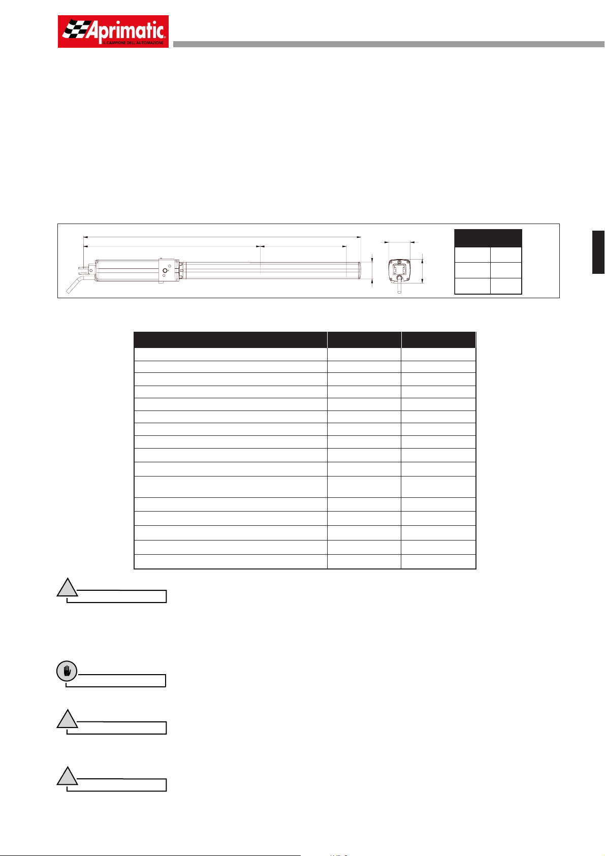
1.1 TECHNICAL DATA
CARACTÉRISTIQUES
Single-phase system voltage
Power absorption
Mean pressure
Thrust force at 10 bar
Traction force at 15 bar
Rod retraction time (max. stroke)
Rod extension time
Max leaf length
Min leaf length
Operating temperature range
Max distance between centres for mounting
holes with fully extended rod
Max stroke - standard arm
Weight with oil
Oil quantity
Oil type
Protection degree
B
A
C
ZT4 C
230 V±10% 50 Hz
250W 250W
30 bar
962 N
1140 N 1140 N
21,5 sec
1,8 m 3 m
1,2 m 1,2 m
-20° / + 70°C
1002 mm
270 mm
8 Kg
0,6 lt.
Aprimatic Oil HC13
IP 55 IP 55
70
± 5
90
97,5
ZT4 SF
230 V±10% 50 Hz
30 bar
962 N
17,5 sec17,5 sec
21,5 sec
-20° / + 70°C
1002 mm
270 mm
Aprimatic Oil HC13
8 Kg
0,6 lt.
± 5
A (mm)
B (mm)
C (mm)
ZT 4
1060
698
274
English
!
The noise level of the above models, referred to the working of the operator, independently of the gate leaf and the post, falls
within the maximum limits set by EEC standards.
Warning
1.2 CHOOSING THE TYPE OF AUTOMATION
Before mounting, choose the type of automation on the basis of the characteristics and dimensions of the element to be operated.
Caution
• The choice of the most suitable type of automation assures an effi cient operation of the unit and minimises the possibility
of failures.
!
• The versions listed above are also recommended for use with solid gate leaves (with the operator inaccessible when
the gate is open).
• The C version model, suitable for use in windy areas, must not be fi tted to gate leaves of up to 1.8 m.
!
The peripheral speed of the gate leaf must always fall within the limits of the current safety regulations. Also, it is important
to avoid the use of high-speed operators on wide gate leaves, as this could cause the leaves to bang violently against the
gate stop (see the “Technical Data” table).
Warning
Warning
- 15 -
English
Preliminary operations
2. DESCRIPTION OF THE
AUTOMATION SYSTEM
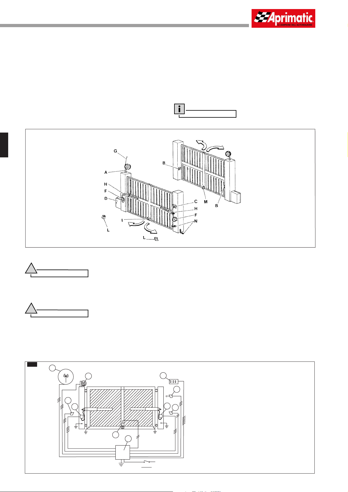
2.0 COMPONENTS LAYOUT (B2)
A - Aprimatic fl ashing warning/courtesy lamp (to be positioned at a
point clearly visible from both approaches)
B - Aprimatic safety photocell
C - Manual key-operated control unit (magnetic, digital, keyboard
combination lock, mechanical, etc.)
D - Aprimatic microprocessor control unit in watertight container (if
possible, to be fi tted in a position sheltered from atmospheric
agents)
F - Watertight operator electricity supply junction box
(recommended), to be positioned so that cables are not subject
to dangerous stretching during the gate motion
G - Antenna
H - Aprimatic ZT series operators
I - Electric lock (optional)
L - Open position gate stop
M - Close position gate stop
N - Ground connection for metal framework
Information
Consult the price-list for additional (optional) safety devices.
2.1 SYSTEM ELECTRICAL CONNECTION
- When making the electrical connections,carefully follow the instructions for each of the components, referring to the wiring diagram D1.
!
• Make the electrical connection of the single components after having completed their installation.
• The entire circuit must be made consistent with the current safety regulations.
• Use cables with a cross-section of 1.5 mm
• Protect the operator power cable with a sheath if necessary; do this before connecting the cable to the junction boxes.
!
• Every operator comes complete with a pickup capacitor. During installation, connect the capacitor to the electrical equipment
according to the wiring diagram supplied.
- After making the electrical connections, check the thrust force at the end of the gate leaf; if necessary, adjust the pressure of the operator
according to the procedure described in the specifi c paragraph.
D1
Warning
Warning
1
2
for the wiring.
2
5
1 Antenna
6
3
9
9
4
2 Flashing lamp
3 Receiver photocell
4 Transmitter photocell
5 Internal control panel
6 Key control
7 Electrical lock
7
8
8 Electronic control unit
9 Junction box
6A
0,030 A
- 16 -
Preliminary operations
3. CHECKS AND OPERATIONS PRIOR TO THE INSTALLATION OF THE OPERATOR
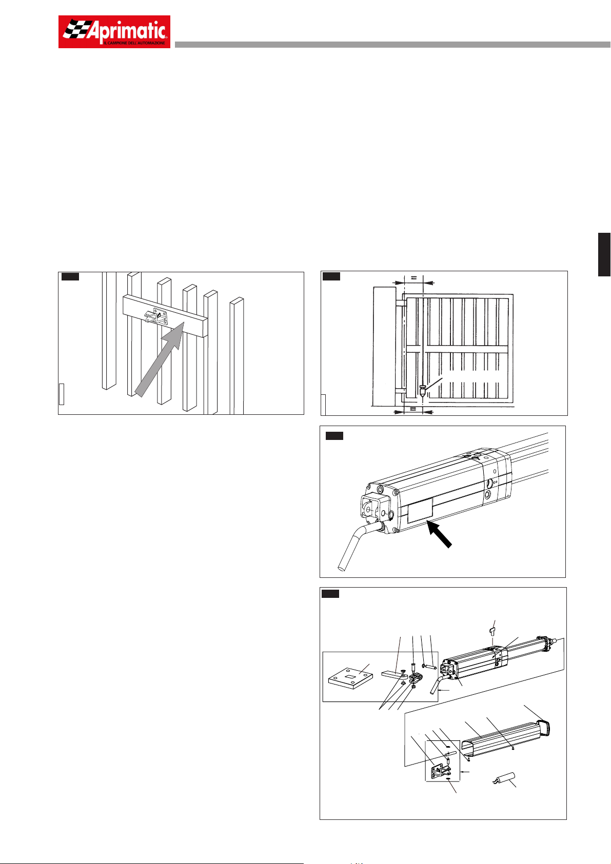
3.0 CHECKING THE GATE
• Before proceeding with the mounting, do a complete check on the gate leaves making sure that they are in good condition and
not broken or damaged in any way.
• Ensure the motion of the gate leaves is uniform and the hinges have no play and do not rub.
Otherwise, hinges must be repaired so that the gate leaves can be moved easily by hand or, if repair is impossible, hinges must
be replaced.
• Check that the gate leaves are plumb (when perfectly still at any point in the swing) (B1B); when the gate leaves are completely closed,
check that the closure is even throughout the whole height of the gate leaves.
• Using a dynamometer, check that the opening and closing effort of the gate, to be measured from the end of the gate leaf, does
not exceed 15 kg (147 N).
Before deciding on the fi nal position of the mountings, it is necessary to:
• Choose the most suitable height on the gate leaf for the operator front mounting. If possible, it should be positioned halfway up the
gate leaf. As a rule, the ideal point is always in the strongest area where the fi xing of the gate leaf has the least effect. If there is not a
broad strip of steel in the gate framework, then a suitable support needs to be welded on in the area where the front mounting is to be
positioned in order to spread the load over a wide zone (B1A).
• Check whether the chosen area needs reinforcing or strengthening in any way. Make the same check on the gate leaf support posts.
B1A
AP030002
3.1 CHECKING THE OPERATOR COMPONENTS
Check that the model code displayed on the operator packaging
corresponds to the code on the identifi cation plate on the operator
itself (B3).
Also,before starting with the mounting procedure, check that the
packaging contains all the components listed below (B4) and that
none of them is damaged.
1 - Operator
2 - Rod protection casing
3 - Rod proctection casing cover
4 - Rear mounting
5 - Bushes
6 - Fork
7 - Rear pin
8 - Locknut
9 - Fork pin
10 - Snap ring
11 - Front mounting
12 - Front mounting pin
13 - Snap ring
14 - Capacitor
15 - Self-threading screw
16 - Release key
17 - Plate for rear mounting
A - Complete front mounting assembly
B - Complete rear mounting assembly
B1B
AP030003
B3
B4
English
PLUMMET
eee eee
eee eee
x eee
............
16
9
10
7
4
17
10
B
5
8
6
15
13
12
11
15
2
1
3
- 17 -
A
13
14
 Loading...