


Scopo del manuale
Questo manuale è stato redatto dal costruttore ed è parte integrante del prodotto.
Le informazioni sono dirette agli operatori esperti che eseguono l’installazione e la manutenzione straordinaria. Essi devono possedere competenze specifiche e particolari capacità per eseguire correttamente ed in sicurezza gli interventi di loro competenza.
La costante osservanza delle informazioni garantisce la sicurezza dell’uomo, l’economia di esercizio ed una più lunga durata di funzionamento del prodotto. Al fine di evitare manovre errate con il rischio di incidenti, è importante leggere attentamente questo manuale, rispettando scrupolosamente le informazioni fornite. Considerando che tale prodotto va installato in abitazioni residenziali, l’operatore esperto, dopo aver effettuato l’intervento dovrà constatarne la corretta installazione ed il regolare funzionamento. Succcessivamente dovrà istruire l’utente sull’uso corretto del prodotto rilasciando tutta la documentazione prevista del costruttore.
L’indice descrittivo, posto all’inizio, consente facilmente la rintracciabilità degli argomenti di interesse.
Purpose of the manual
This manual has been prepared by the manufacturer and is an integral part of the product.
The information is aimed at expert installers and those carrying out extraordinary maintenance operations.
These persons must be specifically qulified to carry out this work correctly and under the maximum safety conditions.
Scrupulous observance of the instructions will ensure safety for man, economic running and a long product functioning life. To avoid incorrect manoeuvres and therefore the risk of accidents, it is essential to read this manual with care and strictly follow all the instructions given.
As this is a product to be installed in residential buildings, the expert installer, after completing installation must verify that this has been performed correctly and that the product functions smoothly. Subsequently, it is necessary to instruct the user on the correct use of the product providing all the documentation envisaged by the manufacturer.
Objectif de la notice
Ce manual a été rédigé par le fabricant et fait partie intégrante du produit.
Les informations qui y sont contenues s’adressent aux opérateurs spécialisés qui effectuent les opérations de pose et d’entretien extraordinaire. Ceux-ci doivent posséder des compétences et des qulités spécifiques pour effectuer de façon correcte et en toute sécurité les interventions relevant de leur compétence directe. La constante observation de ces informations garantit la sécurité des personnes, une économie d’utilisation et une plus longue durée de fonctionnement du produit.
Lire attentivement ce manual et en respecter scrupuleusement les informations pour éviter toute fausse manoeuvre qui pourrait entratener des accidents. Ce produit doit être posé dans des habitations résidentielles. Après en avoir effectué la pose, l’opérateur devra en vérifier la bonne installation et le bon fonctionnement.
Il devra ensuite informer l’utilisateur sur la bonne utilisation du produit et lui remettre toute la documentation prévue par le fabricant. Le sommaire détaillé, placé au début du manuel, permet de retrouver facilement les sujets à consulter.
Zweck der montageanleitung
Das vorliegende Handbuch wurde vom Hersteller vertaßt und ist Bestandteil des Produkts.
Die darin enthaltenen informationen richten sich an erlahrenes Personal, das sowohl die installation als auch außerordentliche Wartungsarbeiten durchführt. Dieses Personal muß über spezifische Fähigkeiten und Kompetenzen verfügen, um die Arbeit korrekt und unter sicheren Bedingungen durchfüren zu konnen. Die ständige Beachtung der Anweisungen gewährleistet Sicherheit, wirtschaftlichen Betrieb der Anlage und eine längere Lebensdaurer des Produkts. Zur Vermeidung von Fehlern, die zu Unfällen führen könnten, muß das vortiegene Handbuch aufmerksam durchgelesen und die darin enthaltenen Anweisungen genau befolgt werden.
Da das Produkt im Privatwohnbereich installier wird, muß das erfahrene Personal nach der installation die korrekte Montage und den einwandfreien Betrieb überprüfen. Anschließend muß es den Benutzer in den richtigen Gebrauch des Produkts einweisen und ihm die vom Hersteller vorgesehene Dokumentation aushändigen.
Das Inhaltsverzeichnis am Anfang des Handbuchs ermöglicht eine schnelle Ermittlung der jeweiligen Punkte.
Objetivo del manual
Este manual ha sido redactado por el constructor y forma para integrante del producto. Las informaciones que contiene van dirigidas a los operadores especializados encargados de las operaciones de installación y mantenimiento extraordinario. Dichos operadores deberán poseer la competencia especifica y las capacidades necesarias para llevar a efecto correctamente y en condiciones de seguridad las operaciones de las que están encargados. El cumplimiento constante de estas instrucciones garantiza seguridad del personal, economia de uso y un funcionamiento más duradero del producto.
A fin de evitar maniobras incorrectas con el consiguiente riesgo de accidentes cabe leer con atención este manual y respetar escrupulosamente las instrucciones proporcionadas. Puesto que el producto está destinado a la instalación en viviendas, el operador especializado, después de realizar la instalación, tendrá que comprobar la correcta ejecución de la misma y el buen funcionamiento del producto. Luego tendrá que ense-ar al cliente la forma correcta de utilización del producto, entregando toda la documentación facilitada por el constructor. El índice descriptivo inicial permite encontrar con facilidad los temas que interesen.
COD.67954-0024700 3/99
R
L' APERTURA AUTOMATICA
ONDA 500 ONDA 800
MOTORIDUTTORE PER CANCELLI AD ANTE SCORREVOLI PER USO RESIDENZIALE
Istruzioni per l’installazione
GEARED-MOTOR FOR SLIDING GATES AND DOORS FOR RESIDENTIAL USE
Installation Instructions
MOTOREDUCTEUR POUR PORTAILS COULISSANTS POUR USAGE RESIDENTIEL
Instructions pour l’installation
GETRIEBEMOTOR FÜR SCHIEBETORE FÜR PRIVATEN GEBRAUCH
Installationsanleitung
MOTORREDUCTOR PARA PUERTAS CORREDERAS DE USO RESIDENCIAL
Instrucciones de instalación
PER UN CORRETTO MONTAGGIO LEGGERE ATTENTAMENTE LE ISTRUZIONI.
FOR A CORRECT ASSEMBLY, CAREFULLY READ THE FOLLOWING.
POUR UN ASSEMBLAGE CORRECT, LIRE ATTENTIVEMENT LES ISTRUCTIONS.
FÜR EINE KORREKTE INSTALLATION, DIESE ANLEITUNGEN SORGFÄLTING LESEN.
LEER ATENTAMENTE LAS INSTRUCCIONES PARA UN MONTAJE CORRECTO.

|
|
|
|
..........................................................................................Phasing |
|
|
SINGLE |
Power supply (V) ................................................... |
|
230V + 10% (50+60 Hz) |
|
Max. absorbed power (W) ...................................................................... |
|
|
260 |
Capacitor (µF) .................................. |
ONDA 500= 20µF ONDA 800 = 25µF |
||
Working temperature (°C): |
|
|
|
With internal control unit ................................................................. |
|
|
–25/+70 |
With external control unit ................................................................ |
|
|
–25/+90 |
Weight (kg) ............................................................................................... |
|
|
14 |
GEARED-MOTOR/MAX. GATE WEIGHT |
ONDA 500 ONDA 800 |
||
Geared-motor with Z 16 pinion (kg) |
|
500 / 300 |
800 / 500 |
Geared-motor with Z 20 pinion (kg) |
|
300 / 200 |
500 / 300 |
Geared-motor with Z 16 C pinion (kg) |
|
- - / 500 |
|
* S2=15 min; S3=25% |
|
*/** |
*/** |
** S2=30 min; S3=50%
 WARNING
The maximum gate weight is only a partial parameter; to determine the type of geared-motor it is also essential to allow for the smooth sliding of the gate.
MAX. SHAFT TORQUE (daNm) |
3 |
4 |
GEARED-MOTOR/MAX. THRUST FORCE |
|
|
Geared-motor with Z 16 pinion (daN) |
94 |
125 |
Geared-motor with Z 20 pinion (daN) |
75 |
100 |
Geared-motor with Z 16 C pinion (daN) |
92 |
123 |
GEARED-MOTOR/MAX. GATE SPEED |
|
|
Geared-motor with Z 16 pinion (m/min) |
9.7 |
9.7 |
Geared-motor with Z 20 pinion (m/min) |
12 |
12 |
Geared-motor with Z 16 C pinion (m/min) |
9,8 |
9,8 |
A
GENERAL CHARACTERISTICS
Geared-motor on sliding gates and doors up to 500 kg (ONDA 500) or 800kg (ONDA 800) for residential use;
Irreversible worm reduction gear (ratio 1/30) with permanent grease lubrication.
Adjustable torque limiter clutch on fast shaft.
Pinions: Z16 (standard), Z20*, Z16 for chain*.
Electromechanical limit switch (IP55 protection)
Secured to the ground with foundation plate or screw anchors.
Diametral pitch 4 rack: either the plastic or the galvanized steel one can be used; the end travel plates are the same for both.
Triangular key for manual release.
Suitable for T2B control units.
Control unit can be fitted inside the geared-motor .
Ready for internal fitting of the Aprimatic receiver.
*The pinions Z20 and Z16/Chain can be ordered separately.
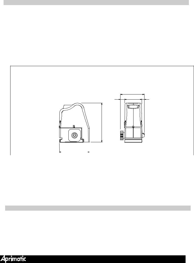
GEARED-MOTOR DIMENSIONS
34 |
188 |
20 |
134 |
||
309 |
|
|
CONTROLLI PRELIMINARI |
|
|
AP006 P7 |
|
|
|
|
0 6 0 0 1 |
|
238 |
|
|
|
A P 0 |
|
|
|
|
|
|
 WARNING
•The gate structure must comply with the current safety regulations.
•The main feature that must be assessed is SMOOTH SLIDING: a good gate MUST be easy to move by hand (with more or less effort, depending
on the weight), to allow opening in the event of manual release.
A list is given below of the main factors that affect the sliding of the gate and its constant performance over time.
GATE CONSTRUCTION
The gate must be stiff, straight and in good condition: eliminate, where present, any type of automatic lock.
AP006 P6

LOWER GUIDES (B1)
B 1
The lower guide must be straight, level, and in good condition.
The wheels must be appropriate to the type of slides used.
 WARNING
•The structure of the gate must comply with the existing safety regulations, specially in the points where there could be a squashing or cutting danger.
•A mechanical stop of the gate in opening (B1 ) must be welded to the lower guide, to prevent the gate leaf from slipping off the guide and, consequently, the DANGER OF FALLING OVER.
ROUNDED-PROFILE GUIDE
V-PROFILE GUIDE
UPPER GUIDES
There must be at least two upper guides fitted linear with the gate, which must prevent the gate from swaying during its travel, and they should not create a hindrance to movement. Fig. B2 shows some examples of installation.
B 2
AP006 P9
B
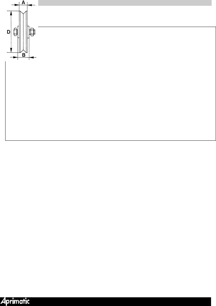
WHEELS (B3)
The wheels must match the guide profile and must be in good condition. If not, REPLACE THEM. Moreover, they should NOT BE MORE THAN TWO, placed close to either end of the gate. Aprimatic supplies different types of wheels; the sizes and relative capacities are indicated in figure B3. When choosing the wheels, apart from the bearing, it must be considered that greater is the diameter, better is the sliding movement of the gates. We suggest not to use wheels with diameters greater than 120 mm.
B 3
|
|
|
|
portata |
|
|
|
|
|
|
|
|
|
|
capacity |
|
|
|
|
portata |
|
D |
A |
B |
C |
|
|
|
|
capacity |
||
port é e |
|
D |
A |
B |
||||||
|
port é e |
|||||||||
|
|
|
|
leistung |
|
|||||
|
|
|
|
peso |
|
|
|
|
leistung |
|
|
|
|
|
|
|
|
|
peso |
||
|
|
|
|
|
|
|
|
|
||
120 |
30 |
34 |
20 |
420 Kg |
|
|
|
|
||
|
|
|
|
|
||||||
120 |
30 |
34 |
350 Kg |
|||||||
|
|
|
|
|
|
|||||
160 |
30 |
44 |
20 |
530 Kg |
|
|||||
|
|
|
|
|
||||||
160 |
30 |
44 |
440 Kg |
|||||||
|
|
|
|
|
|
|||||
200 |
30 |
44 |
20 |
600 Kg |
|
|||||
|
|
|
|
|
||||||
200 |
30 |
44 |
560 Kg |
|||||||
|
|
|
|
|
|
|||||
|
|
|
|
|
|
|||||
|
|
|
|
|
|
|
|
|
|
AP006 P11
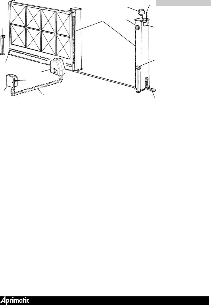
ARRANGEMENT OF THE COMPONENTS (B4)
A- Aprimatic flashing lamp (place in a position that is clearly visible from either side)
B- Aprimatic safety photocell
C- Manual key control device (magnetic, digital, pushbutton combination, etc.)
D- Aprimatic microprocessor control unit (shelter, where possible, from atmospheric agents or inside the geared-motor
Note: in ONDA 500E/ONDA 800E, the T2B appliance is located on the motor
E- Aprimatic Radio-receiver unit - see price list.
F- Cable-way for power supply for geared-motor from the control unit.
G- Antenna
H- Aprimatic geared-motor ONDA 500 or ONDA 800
I- Card for partial sliding opening (pedestrians) - OPTIONAL (see Aprimatic price list)
L- Mechanical opening stop
M- Earth for metal structures
N- Safety edge (active or not active profile) (see price list)
N.B. For other safety devices (OPTIONAL) refer to price list.
|
|
|
|
|
|
|
B 4 |
|
G |
|
|
|
|
|
|
|
|
|
A |
|
|
|
N |
C |
|
|
|
B |
E |
|
|
|
|
|
|
|
|
L |
B |
|
|
|
|
|
|
|
|
H |
|
|
|
|
I |
|
AP006P13 |
|
|
D |
M |
|
|
F |
||
|
|
|
|
|
|
|
|
|
|
AP006 P12
ASSESSING AUTOMATION SELECTED
For a correct choice of the type of geared-motor and the type of installation to be used, experience is very important; there are however some objective criteria that can be of help, as described below:
-Select the pinion according to the estimated weight of the gate (see TECHNICAL DATA). If the gates are less than 300 kg, it is possible to use the Z 20 pinion, but only if the sliding movement is particularly good (the Z 20 pinion must be ordered separately).
-With wooden or very old gates use the Z 16 pinion.
-With wooden gates, it is better to use the plastic rack by verifying the good conditions of the wood in the fixing points.
-The ONDA 500 / ONDA 800 isn’t totally waterproof: therefore we recommend installing the geared-motor slightly raised off the ground. In some areas (where heavy snow occurs or there are flooding risks) the geared-motor can be placed at a height of 20-30 cm.
-Choose the type of fixing (with a foundation plate or with screw anchors) on the basis of the available consistency. Remember that the fixing with screw anchors can be done if the fixing base is good, the support is flat and levelled.
SELECTING SAFETY DEVICES
Apart from the flashing lamp and the photocells, the ONDA 500 / ONDA 800 series make available the following safety systems:
-Clutch (part of geared-motor)
-Active safety edges
All the electric safety devices can be handled by the Aprimatic control units.
ATTENTION
•The selection and installation of the components and safety devices should be performed in compliance with the existing safety regulations.
DEVICES TO PREVENT SQUASHING (ADVICE AND WARNINGS)
CLUTCH
To ensure the safety of the automatic control unit, the geared-motor clutch must be accurately calibrated. If the weight and the smooth sliding of the door require clutch adjustment beyond the limits established by the safety regulations, it is necessary to increase the automation safety level by adding other devices to comply with the safety requirements.
SAFETY EDGES
The safety edges can be used in almost all situations; but they are essential with heavy gates and extreme clutch settings. They can be fitted as opening and closing protective devices on open bar gates.
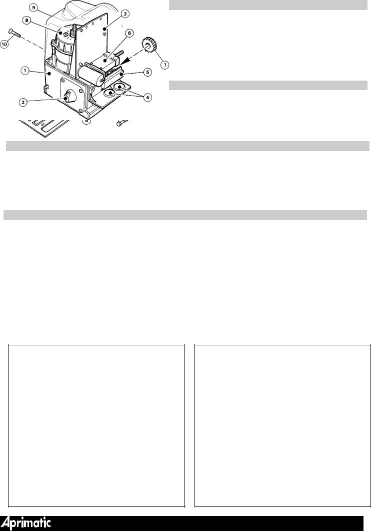
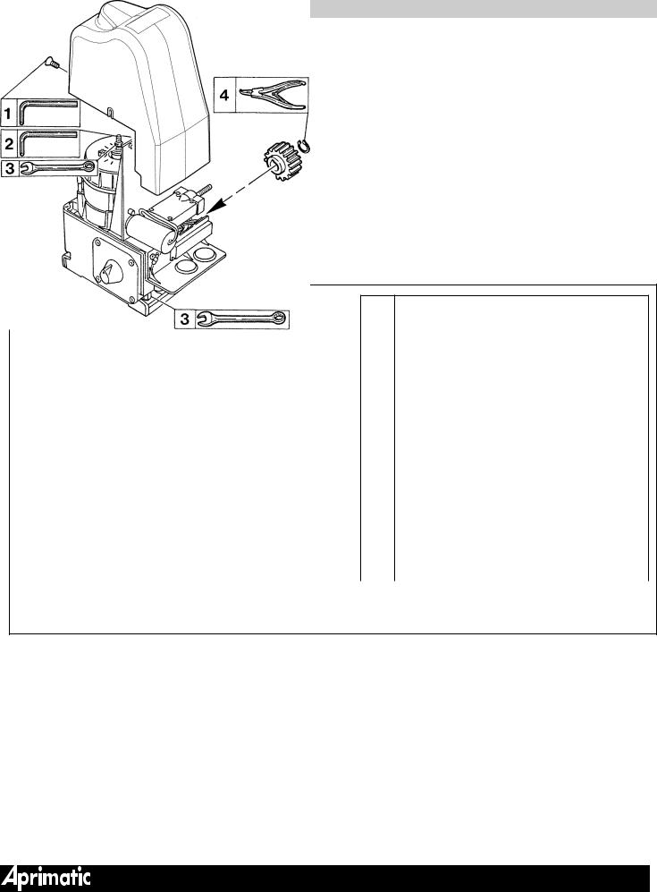
LIST OF COMPONENTS
|
|
PACKAGE CONTENTS (B7) |
|
Internal description (B8) |
Pos. |
Description |
Pos. |
Description |
|
1 |
|
Geared-motor |
1 |
Geared-motor base |
2 |
|
Sliding securing plate |
2 |
Key release |
3 |
|
Release key |
3 |
Plastic support plate |
4 |
|
End travel plate |
4 |
Cable fittings |
5 |
|
Plate securing dowel |
5 |
Terminal board with cover |
|
|
|
6 |
Limit switch |
|
|
To order separately (OPTIONAL) |
7 |
Pinion |
6 |
Plastic rack + installation accessories |
8 |
Electrical motor |
|
7 |
Galvanized steel rack + installation accessories |
9 |
Cover |
|
8 |
Foundation plate |
10 |
Cover securing screw |
|
9Sliding plate securing screw anchors FISCHER S 10 RS 100 or equivalent type (for assembly without plate foundation) - must be bought separately
B 7 |
|
B 8 |
AP006 P14
montar como protección tanto en el cierre como en la apertura con puertas no taponadas.
B
PREPARATION FOR INSTALLATION
The installation of the geared-motor requires a series of preparatory operations on the gate to be automated, if the gate is already installed, at the installation site; it is therefore necessary to prepare the equipment that will give the installer maximum autonomy.
 WARNING The list of tools necessary is given in the figure, including the table, (B9)
BASIC EQUIPMENT AND DISPOSABLE MATERIAL REQUIRED
-Electric disk grinder: 230V
-Protective goggles
-Electric welder: 230V/100 Amp minimum
-Protective mask
-Electrodes minimum dia. 2
-Soft soldering iron
-Electric drill: 230V
-Drill bits
-Cup milling cutter dia. 67 for photocell and push-button housing holes
-Extension cable for electrical equipment
-Electric cable 1.5 mm 2 in various colours+various types of cable terminals
-Electrician’s scissors
-Cable terminal grippers
-Tester
-Calliper in twentieths
-Measuring stick
-Protractor
-Dynamometer
POS. UTENSILE/TOOL/OUTIL/WERKZEUG/UTENSILIOS
1 |
Allen key 2,5 |
USAG USAG |
|
C Allen mâle 2,5 |
|||
280/2,5 |
|||
|
Imbusschlüssel 2,5 |
||
|
|
||
|
Llave Allen macho 2,5 |
|
|
|
|
|
|
|
Chiave a brugola maschio 4 |
|
|
2 |
Allen key 4 |
USAG USAG |
|
Clé Allen mâle 4 |
|||
280/4 |
|||
|
Imbusschlüssel 4 |
||
|
|
||
|
Llave Allen macho 4 |
|
|
|
|
|
|
|
Chiave combinata 13 |
|
|
3 |
Combination wrench 13 |
|
|
Clé combinée 13 |
USAG 285/13 |
||
|
Kombischlüssel 13 |
|
|
|
Llave combinata 13 |
|
|
|
|
|
|
|
Pinza per seeger esterni |
|
|
4 |
Gripper for external snap rings |
USAG 128 |
|
Pinces pour bagues seeger extérieures |
|||
P/10÷25 |
|||
|
Zange für Außenseeger |
||
|
|
||
|
Pinza para anillos de retención exteriores |
|
|
|
|
|
AP006 P20
INSTALLATION OF AUTOMATIC CONTROL UNIT (MODALITY - LAYOUTS)
The installation shown in figure C1 A-B considers the one in which the gate is driven by a rack and pinion system. Geared-motor is secured into the ground with the appropriate sliding plate which permits an easy adjustment of the axial position.
The sliding plate itself can be welded to a foundation plate (C1 A), or (if the base is strong enough) secured into the ground with screw anchors (C1 B) and chemical ones.
A description is also given of the typical layout that must be controlled when the site is inspected (see also fig. C11 for the layout and the positioning of the rack).
The ONDA 500 / ONDA 800 pinion is compatible both with the plastic rack (with a steel core) and with the galvanized steel rack.
ATTENTION
It is essential that, when the site is inspected, the installer makes sure that there is sufficient room near the gate for the layouts illustrated in the drawings.
C 1 |
A |
|
B |
|
|
|
|
|
|
|
|
|
|
|
|
AP006 P22
C
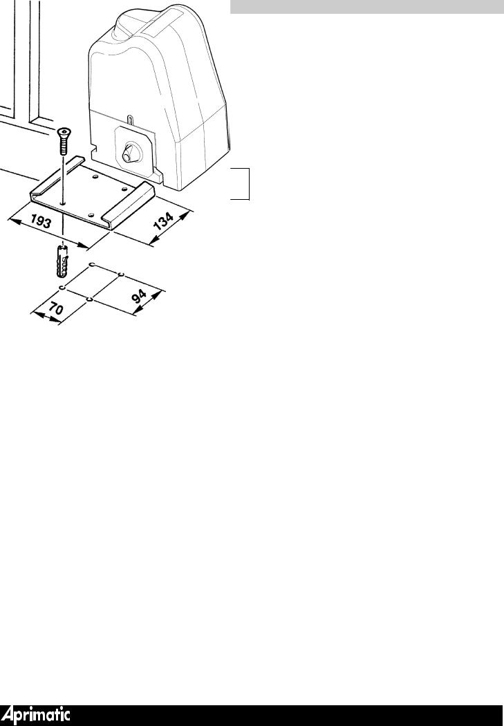
FOUNDATION
Correct functioning of any automatic sliding system depends on the geared-motor being firmly anchored to a structure designed to hold it securely, and good alignment with the gate.
 ATTENTION
It is essential that the foundation be prepared precisely with the foundation plate in the right position with respect to the gate. The geared-motor must be correctly aligned with the gate guide, at the correct distance from the gate, at the right depth, and the electric cable passage bore in the correct position (C2).
Remember also the following points:
-Check the gate opening direction in relation to the position of the cable hole (C2).
-Consider the fixing position of the rack for the vertical position of the supporting surface (C11-C12).
-Avoid executing the foundation with the supporting base below the surface of the ground surrounding the installation; it should be raised a few cm.
 WARNING
In areas subject to heavy snow or with flood risks, the plate should be placed at 20÷30 cm above the ground.
C 2
Foro passaggio cavi
Cable hole
Trou de passage des câbles
Durchgehendes Loch für Stromkabeln
Agujero para el paso de los cables
APERTURA/OPENING/OUVERTURE/
OEFFNUNG/APERTURA
Foro passaggio cavi
Cable hole
Trou de passage des câbles
Durchgehendes Loch für Stromkabeln
Agujero para el paso de los cables
APERTURA/OPENING/OUVERTURE/
OEFFNUNG/APERTURA
AP006 P25
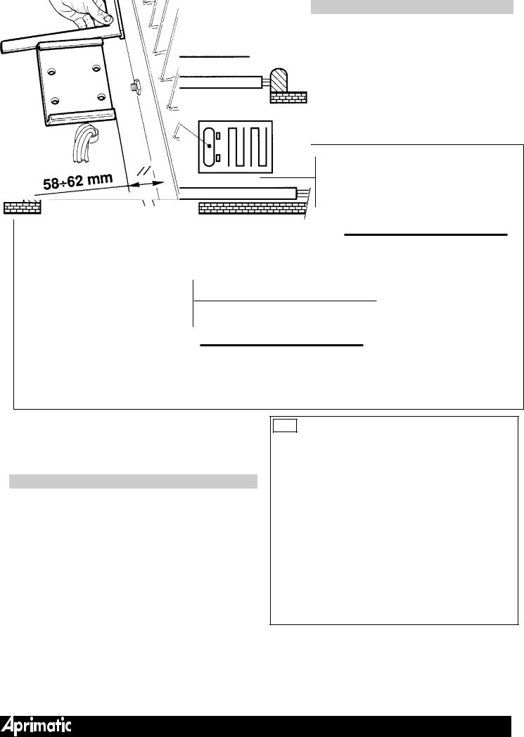
C 3
If the area where the geared-motor is to be fitted already has a good level cement surface, the securing plate can be screwed directly into the ground with COMPACT BUILDING SCREW ANCHORS. (Use Fischer S 10 RS 100, or equivalent, or securing with chemical screw anchors).
ATTENTION
The plate must be aligned with the sliding gate and at the correct distance from the supporting surface of the rack (58+62 mm - C3); moreover, if there is a hole for the fitting of the cables, it must be positioned at the correct distance from it (C4).
ATTENTION
Use allC four4 fixing holes (C4 ) and make sure the plate is integral with the ground.
AP006 P24
C
 Loading...