

Aprilaire 8870 User Manual

Installation Instructions
MODEL 8870
These instructions are for connecting
the Thermostat to the HVAC equipment.
To connect communication features,
please reference the Communicating Thermostat
System Installation Manual.

INSTALLATION INSTRUCTIONS MANUAL
TABLE OF CONTENTS
Warning . . . . . . . . . . . . . . . . . . . . . . . . . . . . . . . . . . . . . . . . . . . . . . . . . . . . . . . . . . . . . . . . . . . . . . .1
Model 8870 Thermostat Specifications . . . . . . . . . . . . . . . . . . . . . . . . . . . . . . . . . . . . . . . . . . 2
1. HVAC System Pre-Installation Check List . . . . . . . . . . . . . . . . . . . . . . . . . . . . . . . . . . . . . . . 2
2. What’s In The Box . . . . . . . . . . . . . . . . . . . . . . . . . . . . . . . . . . . . . . . . . . . . . . . . . . . . . . . . . . . 3
3. Select The Thermostat Location . . . . . . . . . . . . . . . . . . . . . . . . . . . . . . . . . . . . . . . . . . . . . . . 3
4. Disassembly . . . . . . . . . . . . . . . . . . . . . . . . . . . . . . . . . . . . . . . . . . . . . . . . . . . . . . . . . . . . . . . . . 4
5. Mount Base To Wall . . . . . . . . . . . . . . . . . . . . . . . . . . . . . . . . . . . . . . . . . . . . . . . . . . . . . . . . . 5
6. Setting The Dip Switches . . . . . . . . . . . . . . . . . . . . . . . . . . . . . . . . . . . . . . . . . . . . . . . . . . . .6
7. Wiring The Thermostat . . . . . . . . . . . . . . . . . . . . . . . . . . . . . . . . . . . . . . . . . . . . . . . . . 7
8. Reassemble The Thermostat . . . . . . . . . . . . . . . . . . . . . . . . . . . . . . . . . . . . . . . . . . . . . . . . . . 9
9. HVAC System Check Out . . . . . . . . . . . . . . . . . . . . . . . . . . . . . . . . . . . . . . . . . . . . . . . . . . . . . . . 9
10. Optional HVAC Set-Up Features . . . . . . . . . . . . . . . . . . . . . . . . . . . . . . . . . . . . . . . . . . . . 12
11. To Access The HVAC Set-Up Features . . . . . . . . . . . . . . . . . . . . . . . . . . . . . . . . . . . . . . . . .13
Wiring Diagrams . . . . . . . . . . . . . . . . . . . . . . . . . . . . . . . . . . . . . . . . . . . . . . . . . . . . . . 1 6 – 22
Note Pages . . . . . . . . . . . . . . . . . . . . . . . . . . . . . . . . . . . . . . . . . . . . . . . . . . . . . . . . . .2 3 – 25
© Research Products Corporation 2001

1
READ COMPLETE SAFETY & INSTALLATION
INSTRUCTIONS BEFORE STARTING
WARNING
1. 120-volts may cause serious injury from electrical shock. Disconnect
electrical power to the furnace and air conditioner before starting installation.
This thermostat is not a 120-volt (line voltage) device.
2. Improper installation may cause serious injury from electrical shock. This
product must be installed by a qualified heating and air conditioning contractor
in accordance with NEC Standards and applicable local and state codes.
3. Mercury is toxic and may be hazardous to health. Any replaced thermostats
containing mercury must be disposed of properly. Contact local authorities
for disposal information.

MODEL 8870 THERMOSTAT SPECIFICATIONS:
Control Voltage 24V AC ±20%
Switched Voltage 18 – 30V AC
Maximum Operating Current 2.0A total at rated voltage, through all outputs.
1.0A through any one output.
Maximum Surge Current 2.0A
Control Accuracy
±
1.0°F
Control Range 40° – 90°F
Operating Range 32° – 99°F
1. HVAC SYSTEM PRE-INSTALLATION CHECK LIST
Before getting started determine what type of heating system is/will be installed in the house.
Then use Table 1 to determine if the proper numbers of wires are available depending on the
HVAC System. Additional wires will be required for communication system.
TABLE 1
APPLICATION # OF HVAC WIRES DIAGRAM PAGE #
Single Stage Furnace & AC 5 1 16
Two Stage Furnace & Two Stage AC 7 2 17
Roof Top Unit (Two Stage Heat & Two Stage Cool) 7 3 18
Boiler with AC (Two Transformers) 5 4 19
Single Stage Heat Pump 7 5 20
Two Stage Heat Pump 9 6 21
First Stage Radiant Floor Heat
Second Stage Furnace One Stage of Cooling 6 7 22
2
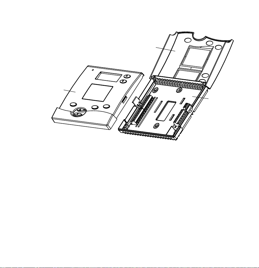
2. WHAT’S IN THE BOX
• Thermostat (Figure 1): front panel, cover, and base
• Installation Manual
• Owners Manual
• Hardware bag: screws and wall anchors
FIGURE 1
3. SELECT THE THERMOSTAT LOCATION
Determine if the thermostat will be operating alone, or with remote temperature sensors.
If the unit is stand-alone there are certain measures that must be taken to ensure accurate
temperature control.
STAND-ALONE THERMOSTAT MOUNTING CRITERIA:
• Mount on an interior wall.
• In a room frequently occupied.
• At least 18 inches from any outside wall.
• Approximately 5 feet above the floor. Check with local building codes for height
requirements in commercial requirements.
3
Front Panel
Cover
Base
DO NOTlocate the thermostat:
• Behind doors, in corners or other dead air spaces.
• In direct sunlight or near lamps, appliances or other sources of radiant heat.
• On an outside wall or wall exposed to an unconditioned space (i.e. garage, etc.).
• In the flow path of a supply register, in stairways or near outside doors.
• On a wall where concealed pipes and/or ductwork will affect the thermostat.
• Near sources of electrical interference such as arcing relay contacts.
WITH REMOTE TEMPERATURE SENSORS
Follow the guidelines for placement of the sensors and locate the thermostat indoors where
operating range (see specs) will not be violated (i.e. do not install in a cold garage or hot
equipment room). See the sensor installation literature for additional details.
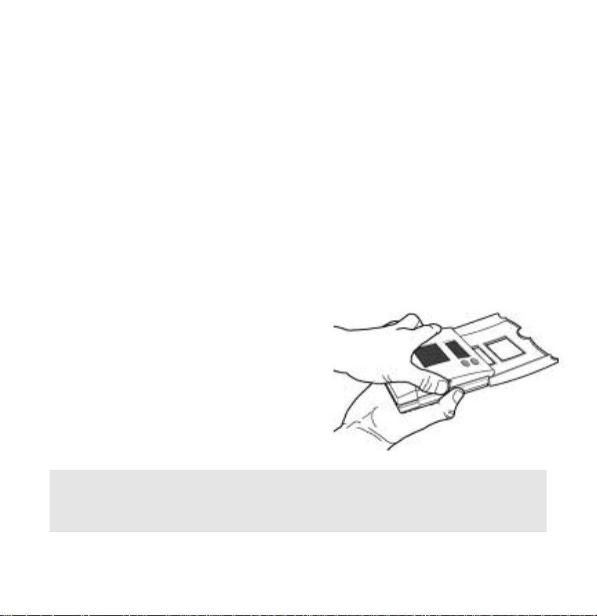
4. DISASSEMBLY
No tools required – use hands to pull the front
panel off of the base (Figure 2). While holding
the base of the thermostat, apply pressure to the
base of the latch with your thumb (Figure 3).
Both sides have a latch, but it is easiest to
unlatch one side at a time.
CAUTION: Loss of internal programs may result from static discharge to thermostat circuit
board. Installer must touch a grounded metal object before handling the circuit board.
FIGURE 2
4
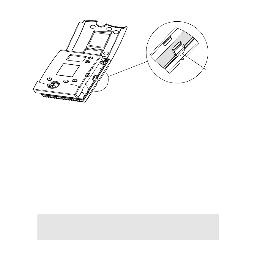
FIGURE 3
5. MOUNT BASE TO WALL
There are four screw holes located on the base of the thermostat; two are for a junction box
mounting, along with two for alternate mounting spacing. Use one of the holes on the top
and one on the bottom.
a) Place the base over the wire hole opening in the wall; level the base and mark the screw
hole mounting locations (leveling required for appearance only).
b) If using supplied wall anchors, drill 3/16" hole in the center of the marked locations and
tap in the wall anchors. If using the supplied screws only, drill a 3/32" hole in the center
of the marked locations.
c) Fasten the base to the wall with the supplied screws.
d) Seal wire entry using caulk, drywall putty or insulation.
CAUTION: Minimize wire entry hole size and seal – drafts from
inside the wall could affect temperature readings.
5
Press
base here
Latch
6
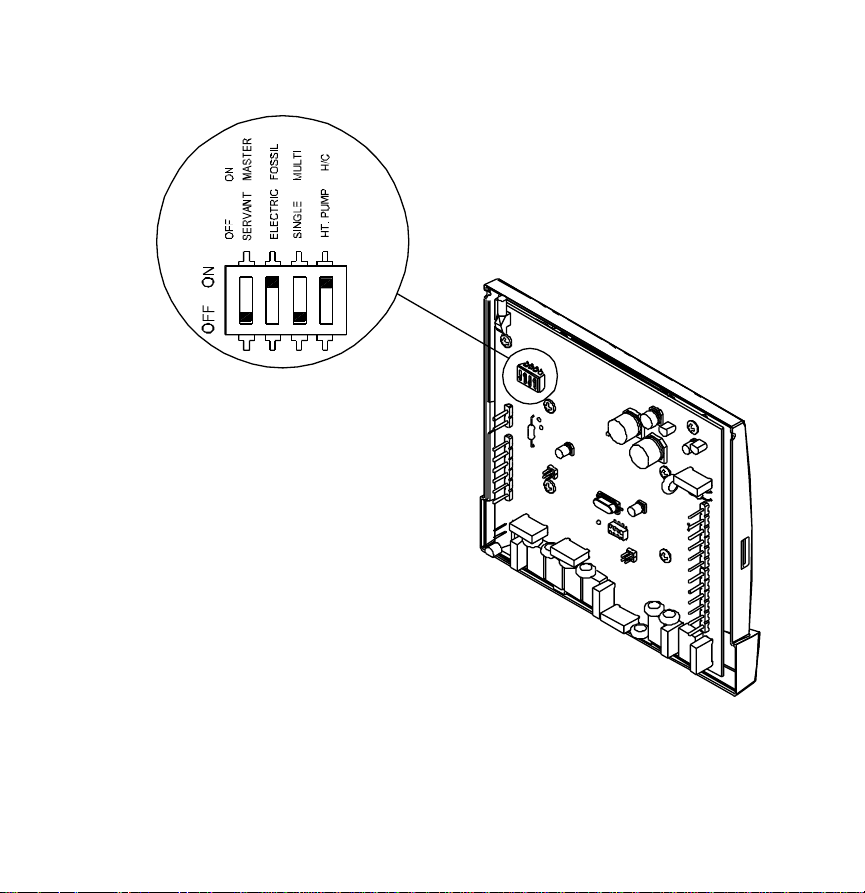
6. SETTING THE DIP SWITCHES
Set the dip switches located on the thermostat circuit
board (Figure 4) according to the application needs (Table 2).
Figure 4 shows what each switch corresponds to depending on posi-
tion. Switch one should be set in the “OFF Servant” position unless you plan to
broadcast readings from remote temperature sensors to other thermostats in the
system when there is no communication system in place.
FIGURE 4
TABLE 2
APPLICATION SWITCH #1 SWITCH #2 SWITCH #3 SWITCH #4
Single Stage Furnace & AC Servant Fossil Single H/C
Two Stage Furnace & Two Stage AC Servant Fossil Multi H/C
Roof Top Unit (Two Stage Heat & Two Stage Cool) Servant Fossil Multi H/C
Boiler with AC (Two Transformers) Servant Fossil Single H/C
Single Stage Heat Pump Servant Electric Single HT. Pump
Two Multi-stage Heat Pump Servant Electric Multi HT. Pump
First Stage Radiant Floor Heat
Second Stage Furnace One Stage of Cooling Servant Fossil Multi H/C
7. WIRING THE THERMOSTAT
a) Strip 1/4" of insulation from each wire to be used. Figure 5 shows all wiring
terminal definitions.
b) Secure wires into the terminals on the base according to the appropriate wiring diagram
(Table 3). Use color-coding practices (i.e. white wire to W terminal) whenever possible.
TABLE 3
APPLICATION DIAGRAM PAGE #
Single Stage Furnace & AC 1 16
Two Stage Furnace & Two Stage AC 2 17
Roof Top Unit (Two Stage Heat & Two Stage Cool) 3 18
Boiler with AC (Two Transformers) 4 19
Single Stage Heat Pump 5 20
Two Stage Heat Pump 6 21
First Stage Radiant Floor Heat
Second Stage Furnace One Stage of Cooling 7 22
7
 Loading...