

Aprilaire 8826 Installation, Configuration And User Manual
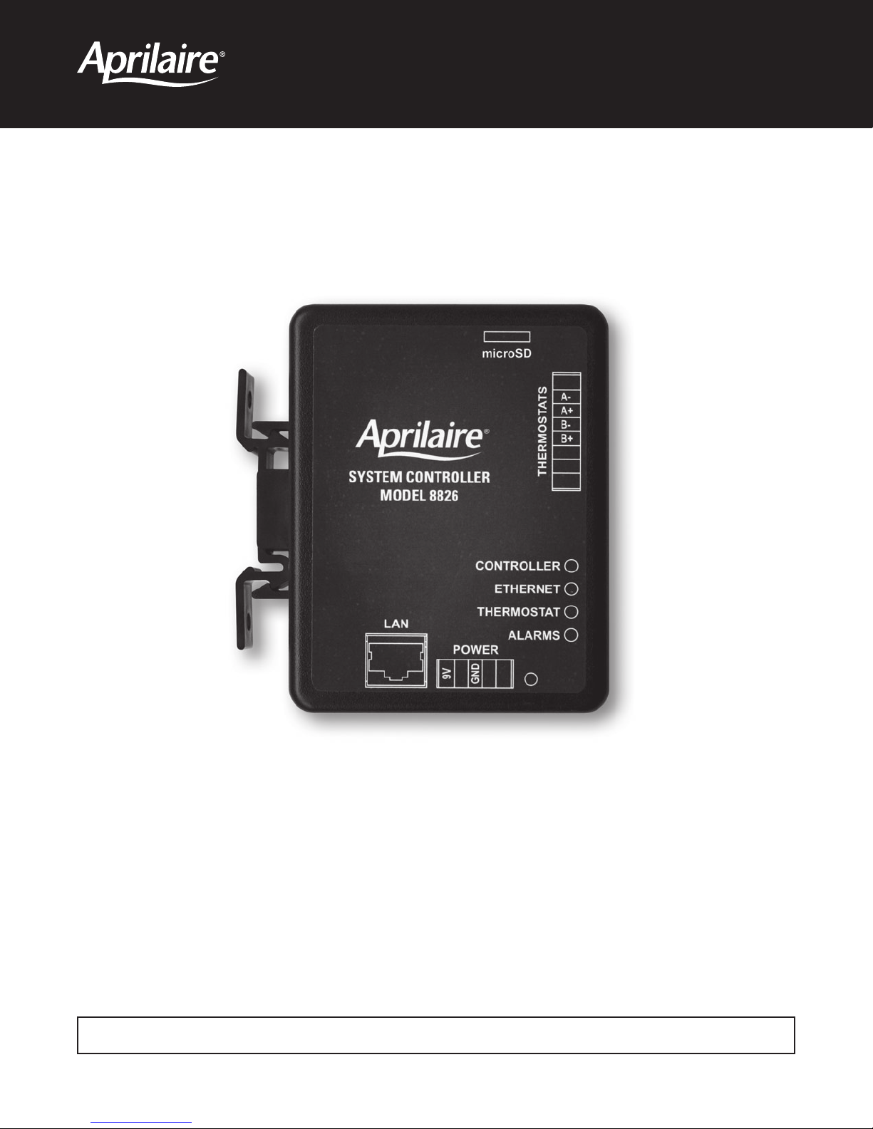
Model 8826 System Controller
Model 8826 System Controller
Installation, Configuration and User Manual
READ AND SAVE THESE INSTRUCTIONS

WELCOME
Thank you for choosing the Aprilaire® HVAC Automation System. With this system you have taken the first step towards total control of a
building’s heating and air-conditioning system. This simple to use, yet powerful system, provides centralized control of all of the buildings
thermostats with an intuitive graphics based software package. The software can be accessed via any computer allowing the means to manage
comfort and control the energy costs that the heating and cooling equipment represent.
TABLE OF CONTENTS
Technical Support .......................................2
System Controller Package Contents ......................2
System Pre-requisites....................................3
Other Useful Documents..................................3
Installation Steps........................................3
Step 1: Mount the System Controller ........................3
Step 2: Provide Power to the System Controller................3
Step 3: Connect the System Controller to the Distribution Panel .....4
Step 4: Connect the System Controller to a Network or Computer....4
Configuring the System Controller for your
Network or Computer ....................................4
On Windows Computers ..................................4
Changing your IP Address ................................5
For Windows XP.........................................5
For Windows 7 ..........................................6
Change your IP Address on your System Controller
to Match your Network Settings ..........................7
To Restore your Computer’s IP Address ....................8
For Windows XP.........................................8
For Windows 7 ..........................................9
System Set-up..........................................10
Temperature Format .....................................10
Service Override ........................................10
Time and Date .........................................10
Number of Thermostats on the Network ....................10
Naming the System Controller ............................10
System Status Bar ......................................10
Adding HVAC and Humidity Control Equipment ............11
Configuring Thermostats and Humidistats.................11
Naming the Thermostats/Humidistats ......................12
Assigning Heating and Cooling Equipment (Thermostat Only)....12
Lockouts ..............................................12
Service Reminders (Model 8800 Thermostats Only)............12
Sensors ...............................................13
Security ...............................................14
Humidistat Set-up ......................................15
Thermostat Set-up . . . . . . . . . . . . . . . . . . . . . . . . . . . . . . . . . . . . . . 15
Scheduling.............................................16
Master Schedules ......................................16
Holidays ..............................................17
Holds.................................................18
Individual Holds ........................................18
Status .................................................19
Setting Alarms .........................................20
Alarms................................................21
E-mail Alerts...........................................21
Service Reminders ......................................22
Firmware Update . . . . . . . . . . . . . . . . . . . . . . . . . . . . . . . . . . . . . . . 24
LED Diagnostics ........................................25
Limited Warranty .......................................26
Warranty Registration ...................................26
System Requirements ...................................27
TECHNICAL SUPPORT
If you have any questions or concerns regarding the installation or operation of this system, DO NOT take the product back to your distributor.
Please contact Aprilaire at 888-782-8638 for system integrator support.
You may need to work with an IT professional to properly configure your e-mail settings and/or configure your network to provide access to the
System Controller from outside your local network.
SYSTEM CONTROLLER PACKAGE CONTENTS
1. The Model 8826 System Controller
2. Power Supply
3. Installation, Configuration and User Manual
4. Eight Position Connector for wiring the System Controller to the Distribution Panel
2
SYSTEM PRE-REQUISITES
These instructions assume that you have already installed the thermostat(s) and wired them to the Distribution Panel according to the Model
8800 System Installation Instructions (Document 10009416).
If your thermostats are configured as non-programmable, all schedules are stored in the System Controller and setpoints are written out to
the thermostats at the beginning of each schedule event. If the thermostats are configured as programmable, the schedules are stored in the
thermostats. This is advantageous because if communication to the System Controller is disrupted, the thermostats will continue to run the
programmed schedule.
In programmable mode, Progressive Recovery can be enabled at the thermostat. The Progressive Recovery feature allows the thermostat to
activate the heating and cooling equipment PRIOR to a scheduled event in order to reach the desired temperature at the start of that scheduled
event. Example: If the WAKE time is 6 am, and the temperature is 70°, the heat will come on before 6 am, so the temperature is 70° by the
time you wake at 6 am.
IMPORTANT NOTE: Set the thermostat ID numbers to consecutive numbers beginning at 1.
OTHER USEFUL DOCUMENTS
The following documents will be useful in installation and
setup of a system using Model 8870 thermostats:
Model 8870 Installation Instructions (Document 61000494)
Model 8870 Operating Instructions (Document 61000491)
Model 8061 TT Support Module Installation Instructions
Model 8062 TrH Support Module Installation Instructions
Model 8870 System Installation Instructions (Document 10008222)
Model 8870 Programmer’s Manual (Document 10005756)
The following documents will be useful in installation and
setup of a system using Model 8800 thermostats:
Model 8800 Installation Instructions (Document 61000761)
Model 8800 Operating Instructions (Document 61000762)
Model 8081/8082 Support Module Installation Instructions
(Document 61000793)
Model 8800 System Installation Instructions (Document 10009416)
Model 8800 Programmer’s Manual (Document 10009414)
INSTALLATION STEPS
To install the System Controller you will need to complete the following steps, which are described in the following sections:
1. Mount the System Controller in a suitable location.
2. Connect the System Controller to a network or computer.
3. Connect the System Controller to a Distribution Panel.
4. Connect power to the System Controller using the included power supply.
STEP 1: MOUNT THE SYSTEM CONTROLLER
The System Controller should be mounted to a wall at a location that:
•Providesaccesstoapoweroutlet.
•ProvidesaccesstoanEthernetnetworkconnectionifyouplantoaccesstheSystem
Controller over a network.
•ProvidesaccesstowiretheRS-485communicationstothedistributionpanel.
The System Controller should be mounted in a dry location that maintains normal temperatures
between 40°F and 100°F.
The System Controller does not need to be accessed in normal operation, but should be
accessible for servicing.
51
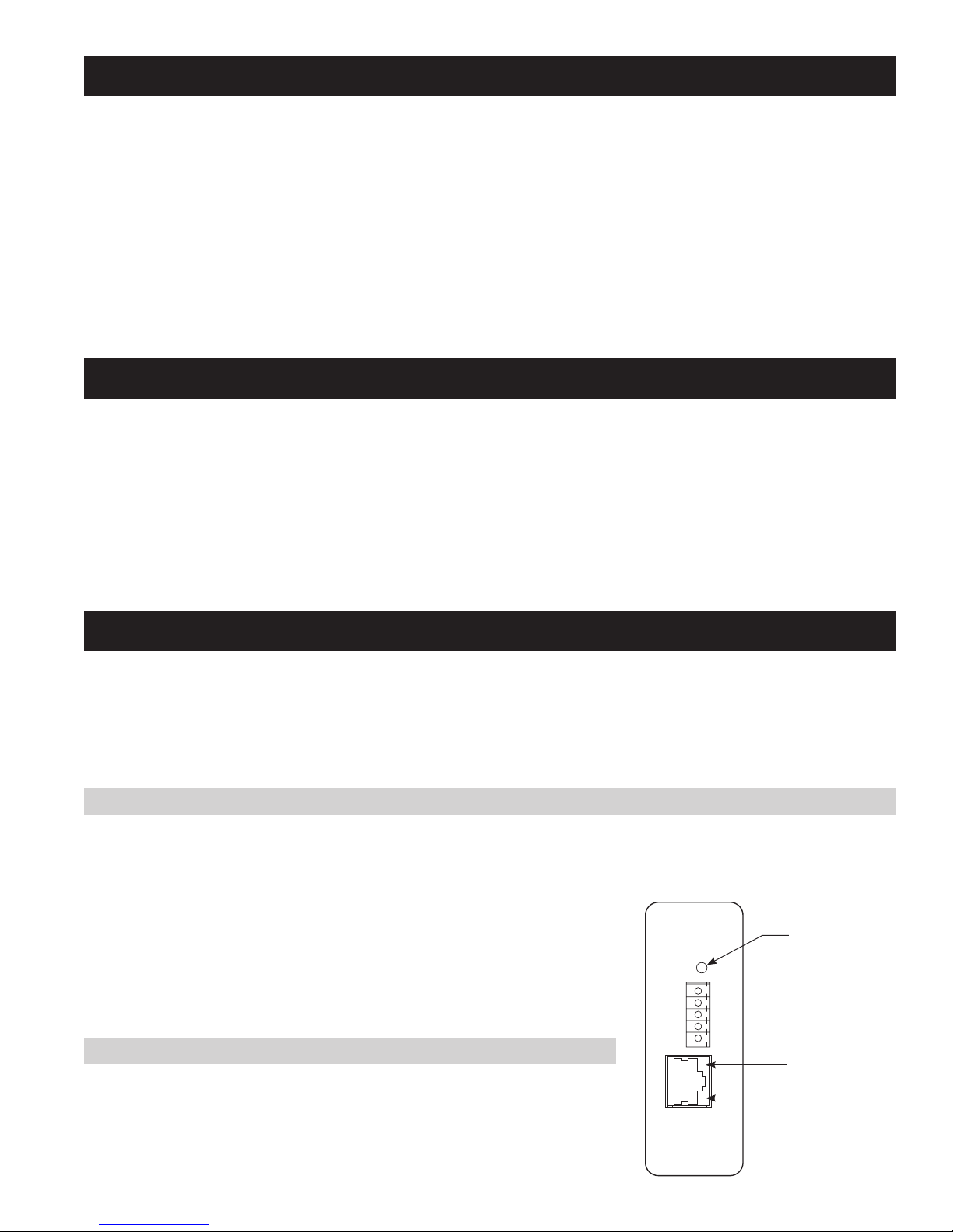
PWR
“POWER” INDICATOR
STEP 2: PROVIDE POWER TO THE SYSTEM CONTROLLER
The System Controller comes with a power adapter that plugs into a normal 120VAC outlet.
Simply plug the power adapter into an electrical outlet and connect the power plug to
the 5 position connector on the 8826. It is highly recommended to use a surge protected
uninterruptible Power Supply to power the 8826.
Illumination of the Power LED on the System Controller indicates power has been established.
“LINK” LED
“SPEED” LED
ETHERNET
3
STEP 3: CONNECT THE SYSTEM CONTROLLER TO THE DISTRIBUTION PANEL
LAN – TO LOCAL AREA NETWORK OR COMPUTER
The System Controller connects to the distribution
panel on the Thermostat port. The wiring is done
as follows:
Thermostat Port Distribution Panel
Pin 4 B+
Pin 5 B-
POWER
SUPPLY
Pin 6 A+
Pin 7 A-
LAN
POWER
SYSTEM CONTROLLER
Model 8826
THERMOSTATS
DISTRIBUTION PANEL
A-A+B-
B+
A-A+B-
APRILAIRE
B+
STEP 4: CONNECT THE SYSTEM CONTROLLER TO A NETWORK OR COMPUTER
There are two methods to connect a computer to the System Controller; directly to a computer (with a crossover Ethernet cable) or using a local
area network (with a standard Ethernet cable).
If there is no network available, then the System Controller is connected to a computer using a crossover cable. Plug one end of the crossover
cable into the System Controller and the other end into the computer’s network port.
If there is a network available, then use a standard Ethernet cable, plugging one end into the System Controller and the other into an available
Ethernet network jack.
CONFIGURING THE SYSTEM CONTROLLER FOR YOUR NETWORK OR COMPUTER
Once you have completed the installation of the System Controller you are ready to configure the System Controller for use on your network or
with your computer.
The System Controller is sent from the factory with a default fixed IP address of 192.168.0.100. If your computer has an IP address that begins
with 192.168.0 then proceed to the System Set-up section. If you don’t know the IP address of your computer, then proceed as follows:
ON WINDOWS COMPUTERS:
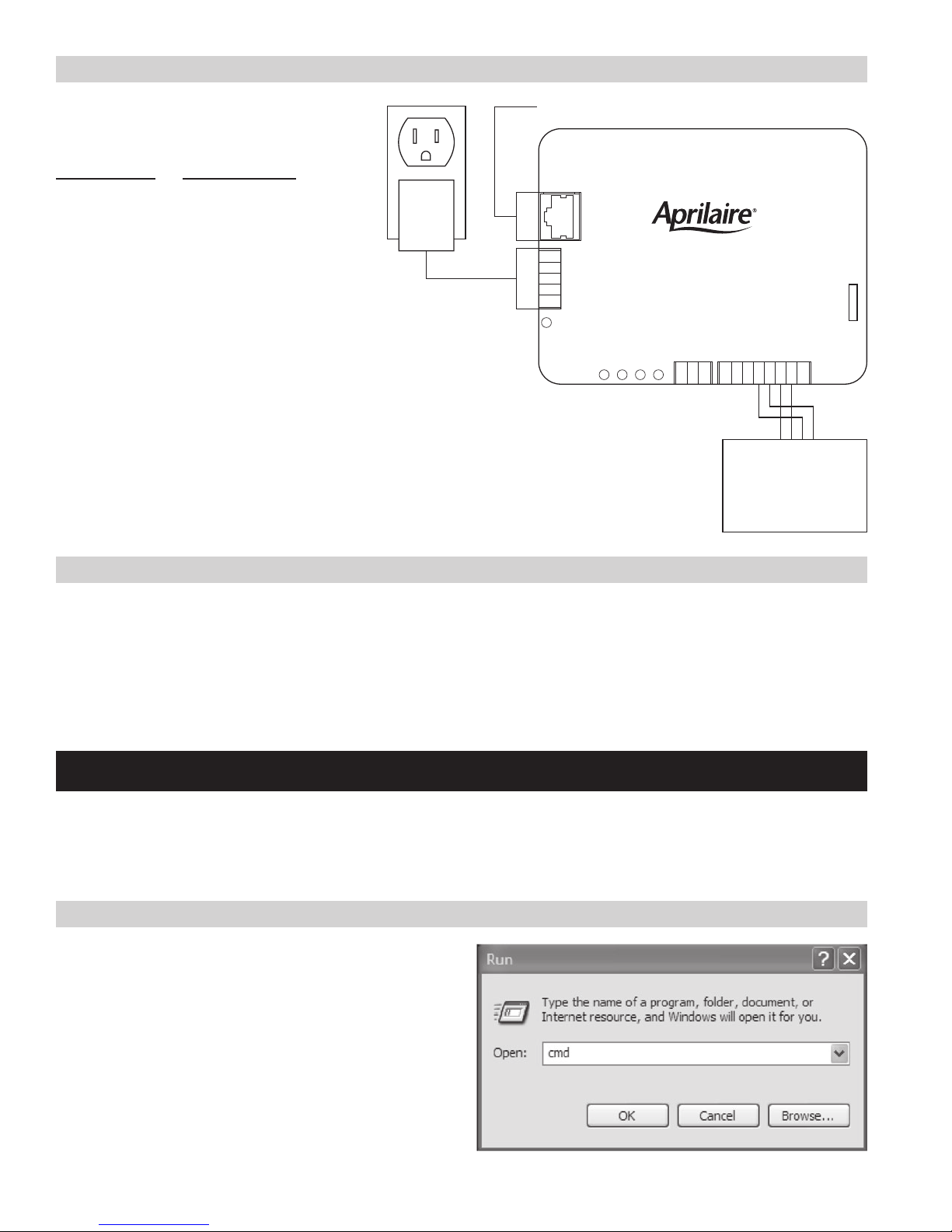
1a. For Windows XP, click on Start, Run to bring up the run dialog
similar to that shown at the right.
1b. For Windows Vista and 7, click on Start and then in the Search
Programs and Files type “run” to bring up the run dialog similar to
that shown on the right.
4
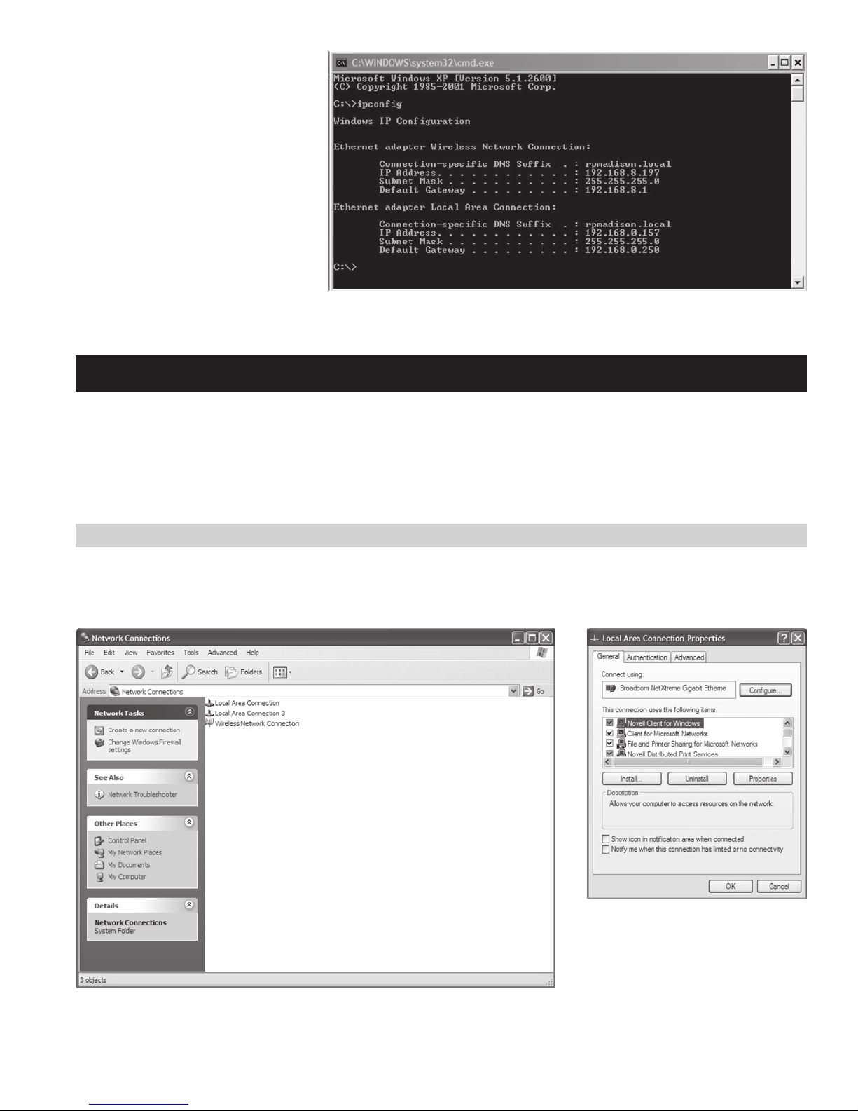
2. Type cmd and then click OK: this will
bring up the command prompt similar to
that shown at right:
3. Type ipconfig and press Enter: several lines including the IP Address of the Local Area Connection will be displayed, as shown above.
CHANGING YOUR IP ADDRESS
If your computer’s IP address begins with 192.168.0 then you can skip this step.
If you computer’s IP address does not begin with 192.168.0 then you need to temporarily change your computer to connect to the System
Controller and change its settings to match your network.
In the following procedure we will change your computer’s IP address so that you can communicate with the System Controller. Once this step is
completed, you can then connect to the System Controller to change it’s IP address to match your network.
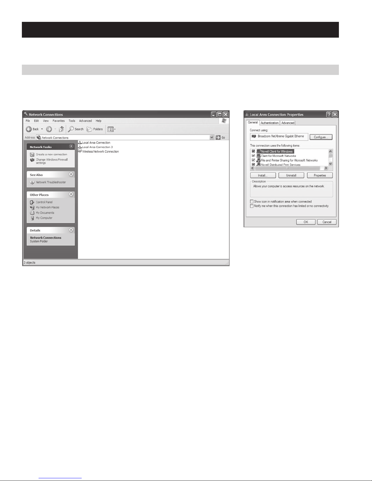
FOR WINDOWS XP
1a. Start the Control Panel by clicking Start, then Settings and Control Panel. In the Control Panel, locate and double click Network Connections
to bring up Network Connections dialog, shown below. Select Local Area connection and then go to File and select Properties to bring up the
Local Area Connection Properties dialog box on the right, below.
5

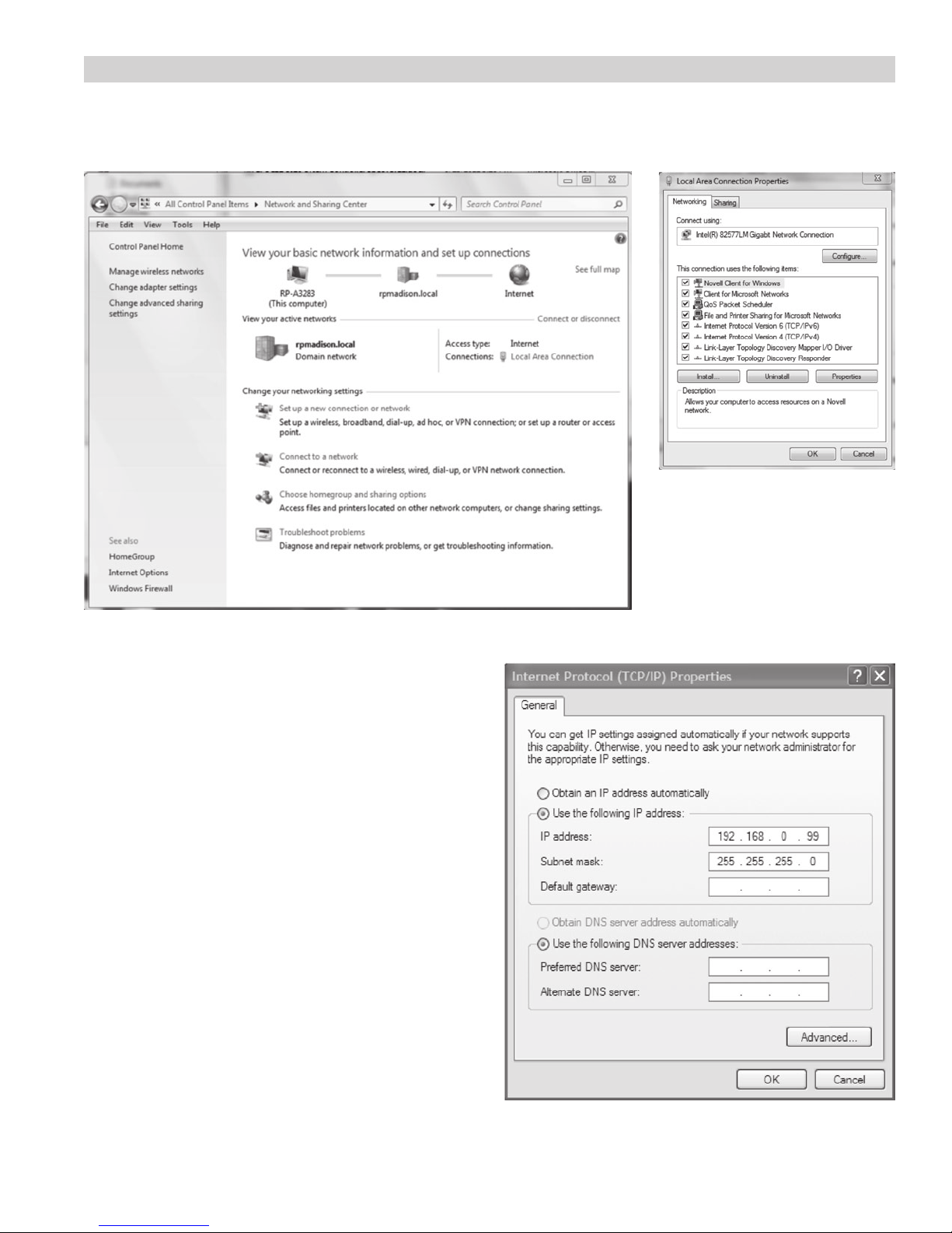
FOR WINDOWS 7
1b. Start the Control Panel by clicking Start, then Control Panel. In the Control Panel, locate and double click Network and Sharing Center to bring
up Network and Sharing dialog, shown below. Double click on Local Area connection and then select Properties to bring up the Local Area
Connection dialog box on the right, below.
2. For Windows 7, select Internet Protocol Version 4 (TCP/IPv4) or for
Windows XP, select Internet Protocol (TCP/IP). Then click Properties
to bring up the TCP/IP dialogs.
3. If the Use the following IP address field is selected, make
a note of the current IP address and Subnet mask for future
reference:
Current IP address:
____.____.____.____
Current Subnet mask: ____.____.____.____
4. If Obtain an IP address automatically is selected instead, then
click Use the following IP address.
5. Set the IP address to a unique IP address, such as 192.168.0.99,
and set the Subnet mask to 255.255.255.0 as shown in the image
at the right and click OK. On some computers you may have to
restart the computer for your changes to take affect.
6
CHANGE YOUR IP ADDRESS ON YOUR SYSTEM CONTROLLER TO MATCH YOUR
NETWORK SETTINGS
The following section describes how
to change the IP address of the system
controller. Perform these steps:
•Ifyouhavefollowedthepreviousstepsto
change your computer’s IP address so that
it starts with 192.168.0, and you are now
ready to set the correct IP address for the
System Controller, or
•Ifyourcomputer’sIPaddressdoesstart
with 192.168.0, but you want the IP
address of the System Controller to be
something other than 192.168.0.100.
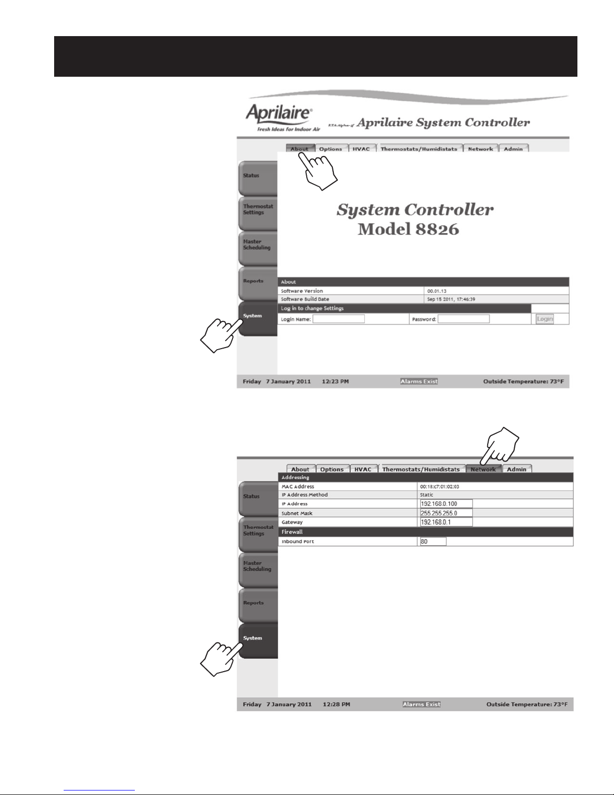
1. Start a web browser on your computer.
2. Place the cursor in the address field and
type http://192.168.0.100 and then press
Enter to bring up the page shown at right.
3. Select the Network tab at the top of the
page. You will see the page at right:
4. Type in the desired IP address and Subnet
mask to match your network.
5. Record the IP address that you entered
below for future reference.
____.____.____.____
7
TO RESTORE YOUR COMPUTER’S IP ADDRESS
If you changed your computer’s IP address to connect to the System Controller, follow these steps to restore your computer’s IP address back to
its original setting.
FOR WINDOWS XP
1a. Start the Control Panel by clicking Start, then Settings and Control Panel. In the Control Panel, locate and double click Network Connections
to bring up Network Connections dialog, shown below. Select Local Area connection and then go to File and select Properties to bring up the
Local Area Connection dialog box on the right, below.
8
FOR WINDOWS 7
1b. Start the Control Panel by clicking Start, then Control Panel. In the Control Panel, locate and double click Network and Sharing Center to bring
up Network and Sharing dialog, shown below. Double click on Local Area connection and then select Properties to bring up the Local Area
Connection dialog box on the right, below.
2. For Windows 7, select Internet Protocol Version 4 (TCP/IPv4) or for
Windows XP, select Internet Protocol (TCP/IP). Then click Properties
to bring up the TCP/IP dialogs.
3. If you wrote down an IP address during step 3 of Changing Your IP
Address, Change the IP address and subnet mask to the previous
values that you recorded. Otherwise, select Obtain an IP address
automatically.
4. Click OK. On some computers you may have to restart the computer
for your changes to take effect.
9
 Loading...