

Aprilaire 8800 Installation Manual
HVAC Automation
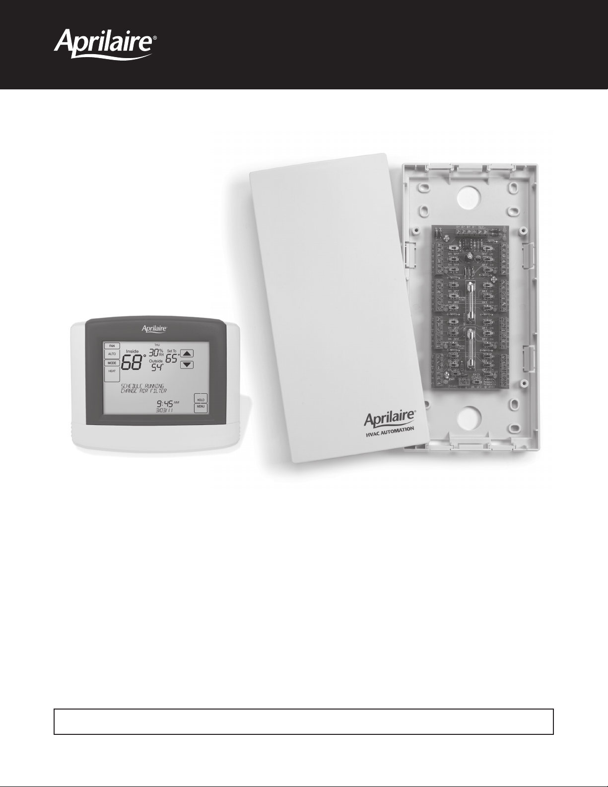
Model 8800 Communicating Thermostat
System Installation Manual
READ AND SAVE THESE INSTRUCTIONS

COMMUNICATING THERMOSTAT SYSTEM INSTALLATION MANUAL
This manual will guide the installer through the installation, wiring and checkout of an Aprilaire® Model 8800 Communicating Thermostat
System. For a complete command set with programming suggestions, see the programming manual (Part No. 10009414). Please visit
www.aprilairepartners.com/docs/literature for this document.
TABLE OF CONTENTS
Collect the components needed ............................................................................................ 3
Disconnect power to all HVAC equipment and/or zone control panels ............................................................. 4
Run the required wires and mount the system components...................................................................... 5
Connect the control wires to the HVAC/zone system and thermostats ............................................................. 7
Connect the communication and power wires to the distribution panel and thermostat ............................................... 8
Connect multiple distribution panels ........................................................................................ 9
Connect protocol adapter to the distribution panel and host computer or automation system ......................................... 10
Check-out HVAC system operation......................................................................................... 11
Set thermostat address and total number of thermostats ...................................................................... 11
Setup computer for communication system checkout .......................................................................... 12
Check-out communications to the thermostat network.........................................................................15
Appendix 1 – Special considerations for installing the Model 8800 with the 8870 Series Communicating Thermostat ..................... 16
Appendix 2 – Sensor averaging ........................................................................................... 17
WARNING
1. 120 volts may cause serious injury from electrical shock. Disconnect electrical power to the HVAC system before starting
installation. This system is a low-voltage system.
2. Improper installation may cause serious injury from electrical shock. This system must be installed by a qualified contractor in
accordance with NEC Standards and applicable local and state codes.
2
COLLECT THE COMPONENTS NEEDED
TOOLS NEEDED
• Small flat head screwdriver for terminal screws (1/8” wide tip).
• Medium size flat/phillips head screwdriver for component mounting
screws.
• Volt/ohm meter.
• Computer with available com port (RS-232) and terminal emulator
such as HyperTerminal (for system checkout).
• Wire strippers.
• Small level (use to mount components level, required for
appearance only).
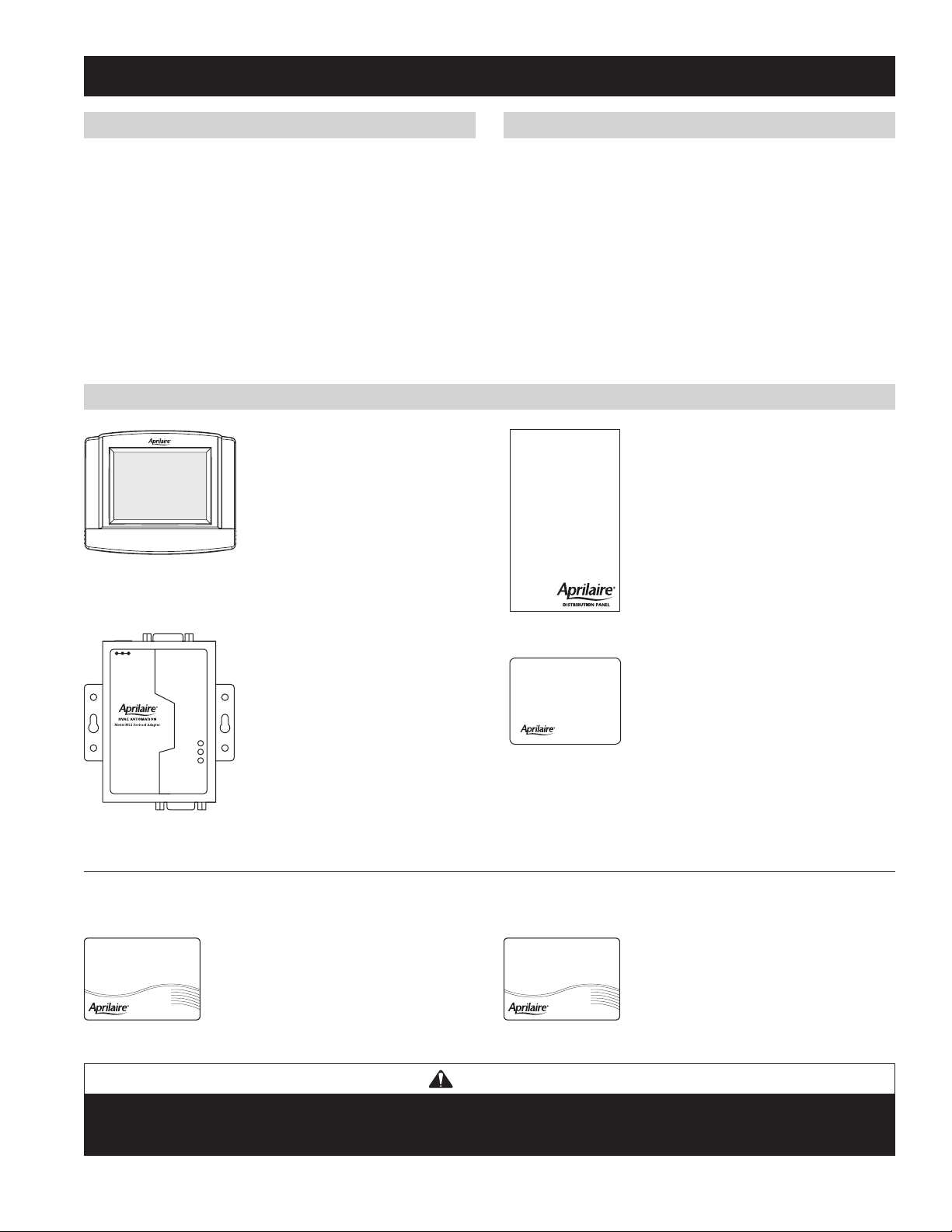
SYSTEM COMPONENTS
Model 8800
Communicating Thermostat
The Model 8800 thermostat is an
RS-485 communicating thermostat,
configurable for single and multi-stage
heat/cool or heat pump systems. It is
also configurable as a whole home
humidifier/dehumidifier control.
WIRE NEEDED
• Multi-conductor thermostat cable (18–20 gauge).
• Category 5 communication wire (4 pair twisted cable).
Model 8819 Distribution Panel
The distribution panel is a switch controlled
communication bus that can be wired to
eight Model 8800 thermostats. This allows
thermostat communication to be turned on
and off at one convenient location which
simplifies installation and troubleshooting.
RS-485/422
DC +9V
TXD
RXD
POWER
RS-232
Model 8811 Protocol Adapter
The 8811 protocol adapter is used to
convert an RS-485 communication signal
to an RS-232 signal that is readable by a
host computer’s serial port.
Automation System Controller
RS-232 or RS-485 based automation system
controller such as the Aprilaire System
Controller.
MODEL 8081 AND 8082 SUPPORT MODULES (OPTIONAL)
Support modules can be added if you require additional temperature or humidity values. Support modules can also be used for sensor averaging
in large areas.
Model 8081 Support Module
Provides two temperature values.
• One onboard or remote temperature sensor.
• One remote temperature sensor.
Model 8082 Support Module
Provides one temperature and one humidity
value.
• One onboard humidity sensor.
• One onboard or remote temperature sensor.
WARNING
Use only the correct support module with each thermostat. Damage will occur if they are mixed.
8800s use only 8081 & 8082 support modules. 8870s use only 8061 & 8062 support modules.
3
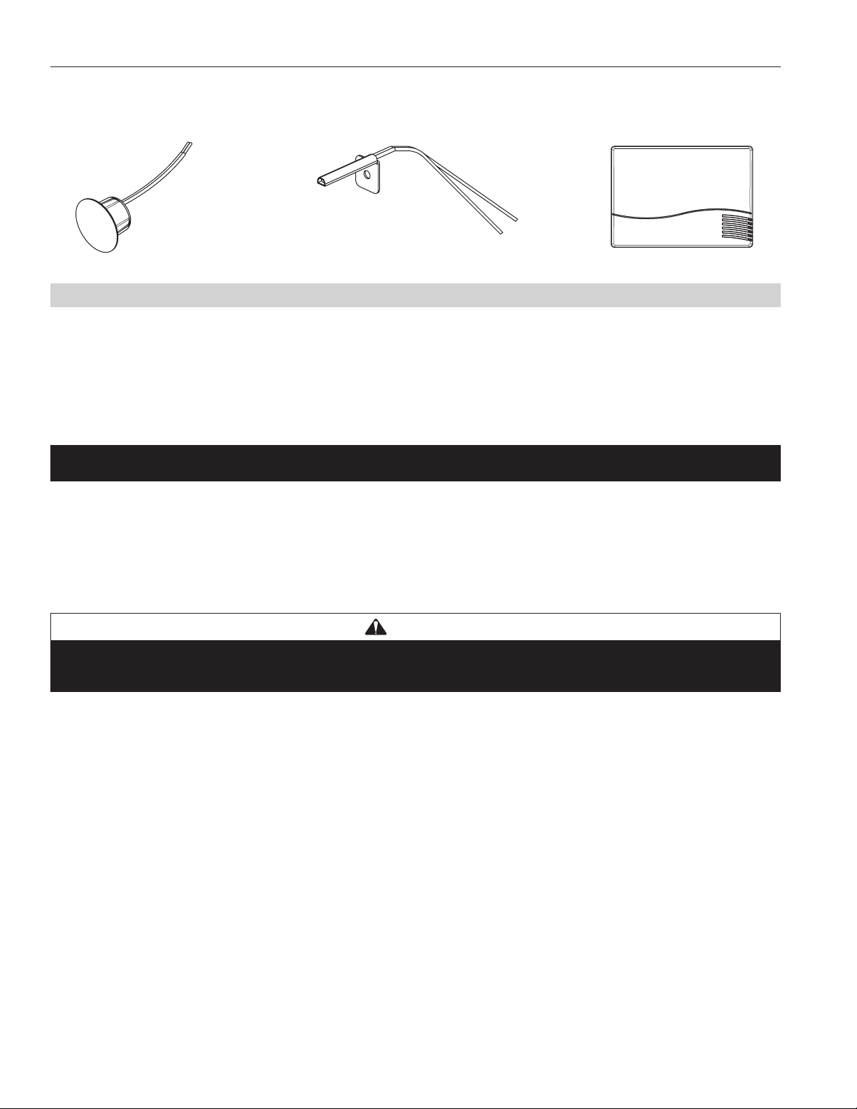
MODEL 8051, 8052 AND 8053 REMOTE TEMPERATURE SENSORS (OPTIONAL)
These sensors can be used directly with the Model 8800 thermostat or with support modules.
Model 8051 Flush Mount Sensor Model 8052 Outdoor Temperature Sensor Model 8053 Wall Mount Sensor
FOR EASE OF INSTALLATION AND TROUBLESHOOTING DO THE FOLLOWING:
• Use Category-5 cable for all communication wiring.
• Check and recheck to ensure connection to the proper terminals before powering up the thermostats. Use wire color as a guide and be consistent.
• Use a Distribution Panel on all systems with more than one zone to simplify wiring and troubleshooting.
DISCONNECT POWER TO ALL HVAC EQUIPMENT AND/OR ZONE CONTROL PANELS
• If the thermostats are wired to a zone control panel, there is generally one set of input terminals supplying power to the thermostats and
dampers. This must be disconnected.
• If the thermostats are wired directly to HVAC equipment, the power must be shut off at the equipment. This can generally be accomplished by
turning off the disconnect switch located near the equipment. If an obvious disconnect switch is unavailable, you will need to turn the circuit
off using the fuse or circuit breaker. Remove the fuse or shut down the circuit breaker serving the equipment.
CAUTION
Failure to disconnect power could result in damage to the HVAC equipment or thermostats. Leave power disconnected until all other
electrical connections have been made and checked for accuracy.
4
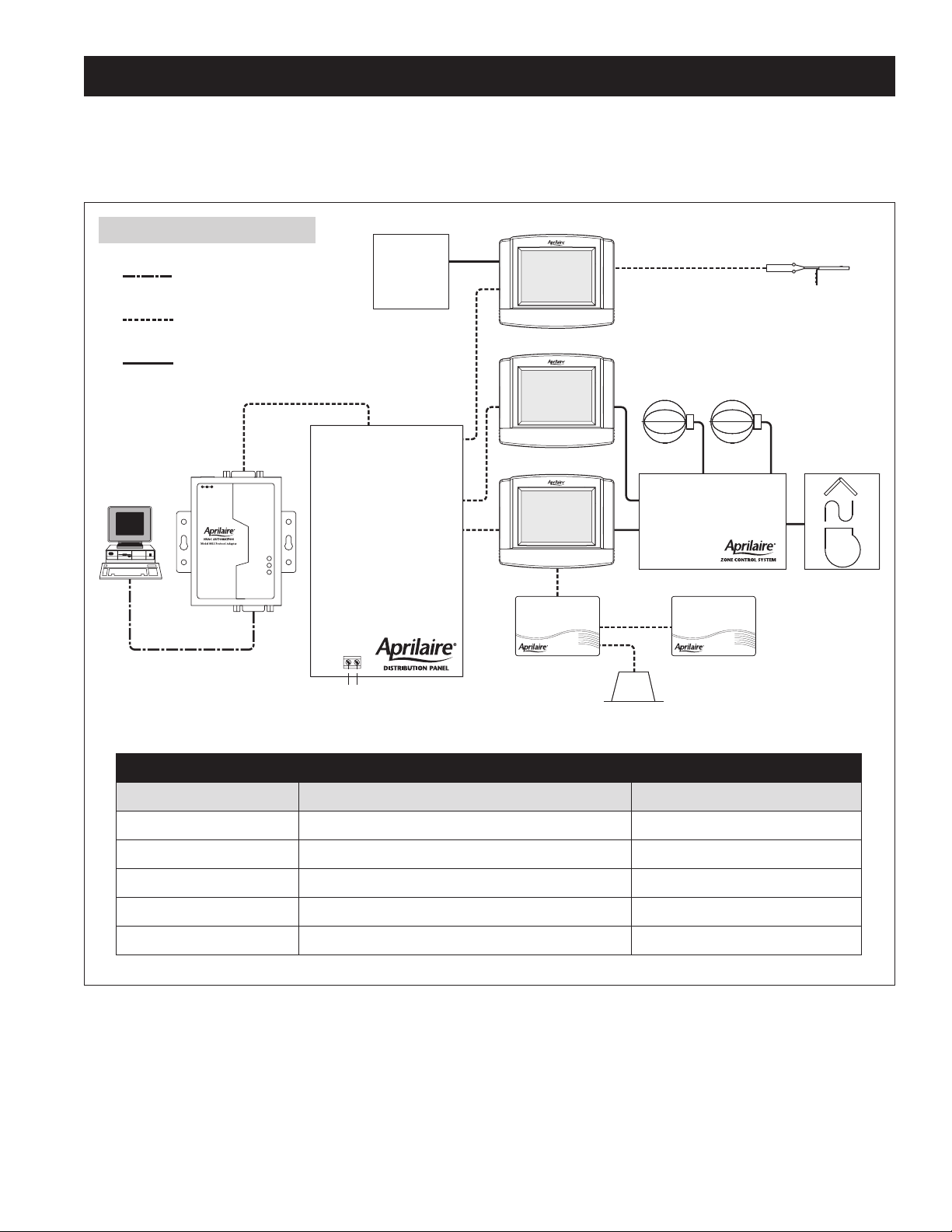
RUN THE REQUIRED WIRES AND MOUNT THE SYSTEM COMPONENTS
1. Determine component locations.
2. Run and label wires. Use FIGURE 1 for selecting wire type.
3. Mount components as specified in each product’s installation instructions.
FIGURE 1 – Run Wire for System
Straight through serial cable
provided with Protocol Adapter
Automation
System
Category 5 (4 pair twisted)
communication wire
Thermostat cable
RS-485/422
DC +9V
Humidifier
Communicating Humidistat
Zone Dampers
Distribution Panel
Communicating Thermostat
Model 8052
Outdoor Temperature Sensor
TXD
RXD
POWER
RS-232
Zone Comfort Control Panel HVAC System
Protocol Adapter
(if needed)
24VAC
RC
Support Module
Support Module
Model 8029
24VAC Plug-in
Transformer
Model 8051
Flush Mount Sensor
Maximum Wiring Distances
From To Maximum Distance
Automation or Computer System Protocol Adapter 3 ft. Cable Provided with Protocol Adapter
Protocol Adapter Thermostat (this includes going through the Distribution Panel) 4000 ft. (cumulative)
Thermostat Support Module 1000 ft. (cumulative)
Support Module Temperature Sensor Option 300 ft.
Thermostat Temperature Sensor Option 300 ft.
5
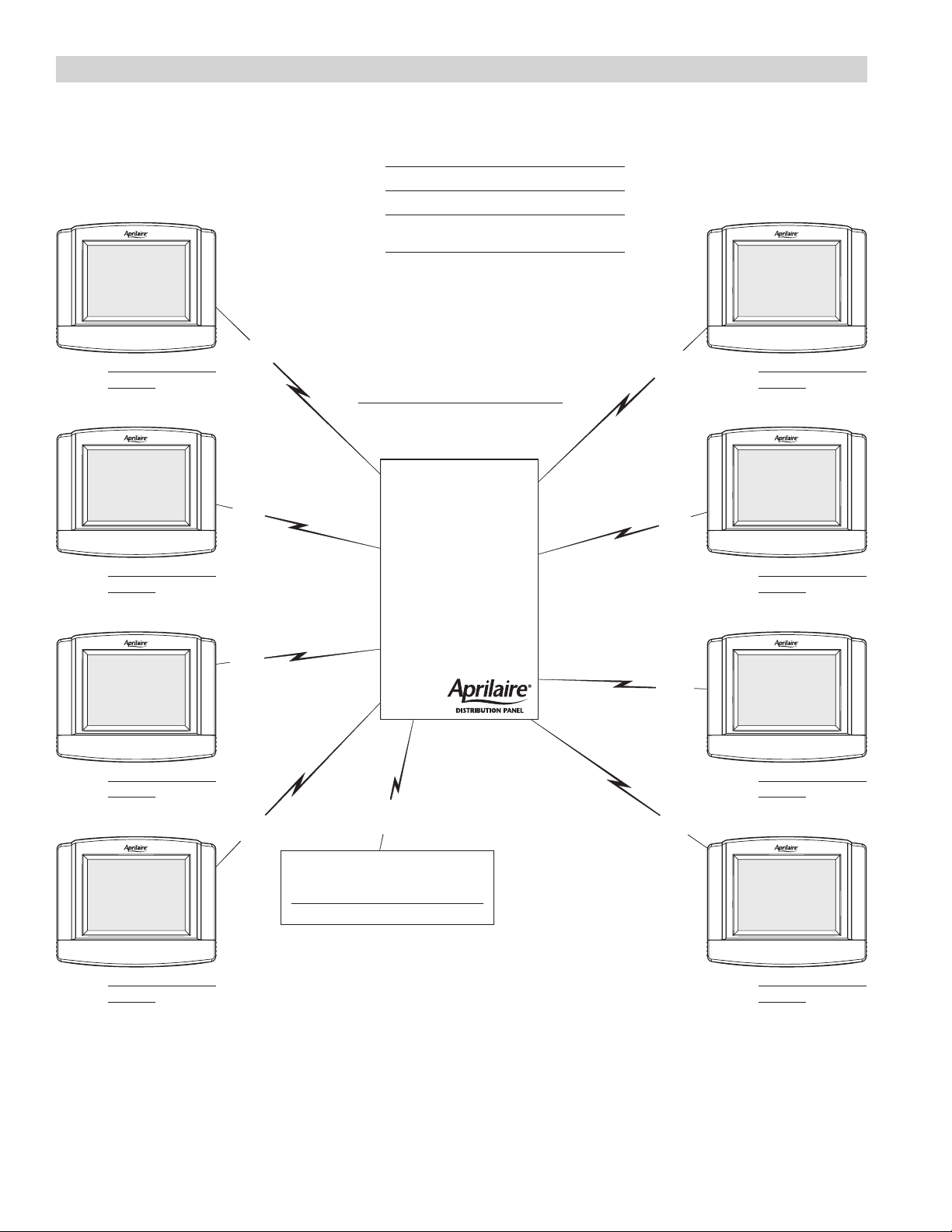
Fill Out and Leave with System Software Package
FIGURE 2 – Network Interconnection Worksheet
JOB TITLE:
JOB LOCATION:
INSTALLING
CONTRACTOR:
CAT-5
WIRE
LOCATION
ADDRESS
DATE:
DISTRIBUTION PANEL LOCATION / NAME
CAT-5
WIRE
LOCATION
ADDRESS
LOCATION
ADDRESS
LOCATION
ADDRESS
CAT-5
WIRE
CAT-5
WIRE
CAT-5
WIRE
CAT-5
WIRE
TO DISTRIBUTION PANEL
CAT-5
WIRE
CAT-5
WIRE
CAT-5
WIRE
LOCATION
ADDRESS
LOCATION
ADDRESS
LOCATION
ADDRESS
6
LOCATION
ADDRESS
 Loading...