

Page 1
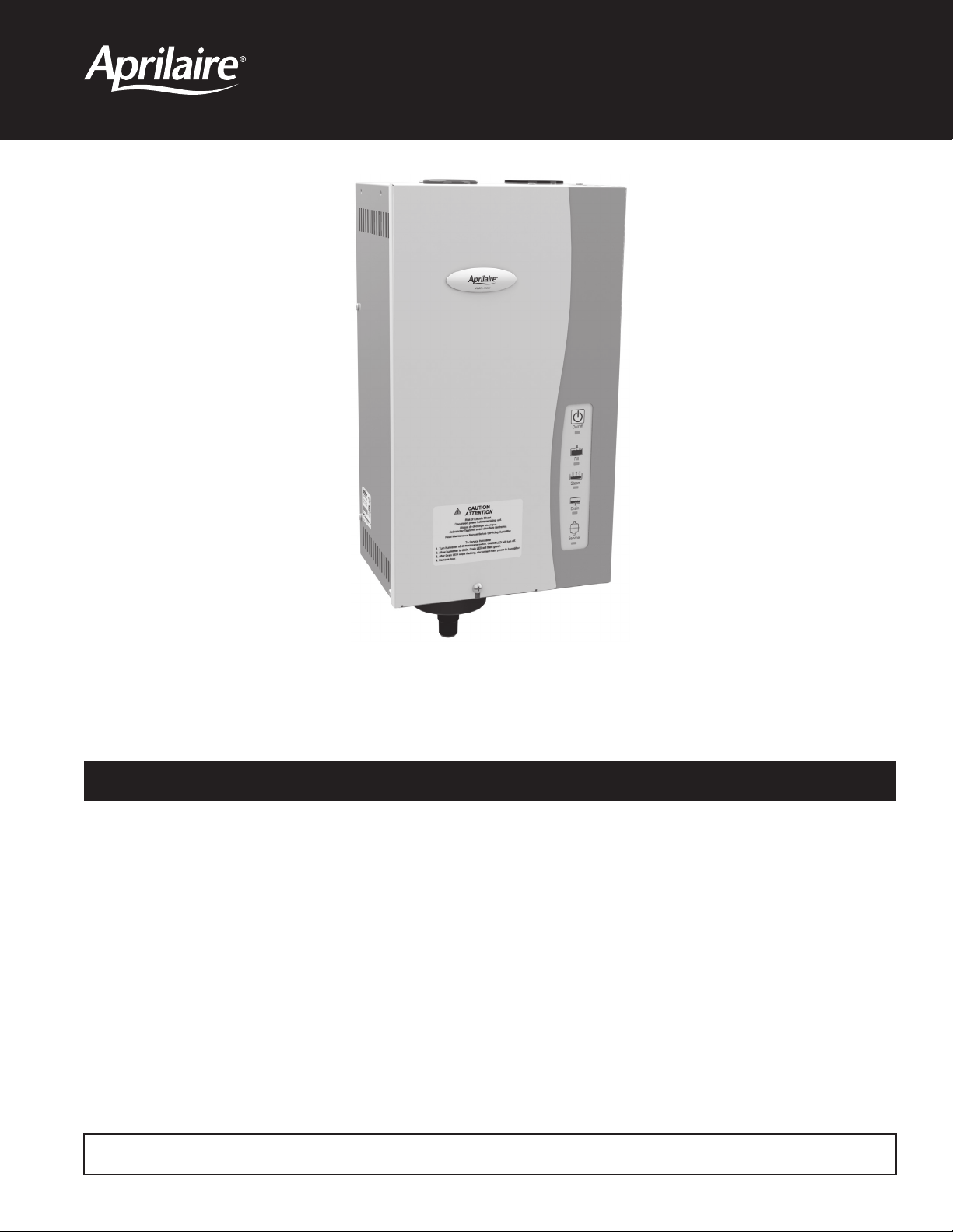
Steam Humidifier
Series 800 Steam Humidifier
Installation & Maintenance Instructions
TABLE OF CONTENTS
Safety Cautions..........................................2
Materials List ...........................................3
Principles & Sequence of Operation.......................4
Specifications & Dimensions .............................5
Installation Instructions ..................................8
Choosing a Location .....................................8
- Dispersion Tube Location ..............................8
- Fan Pack Location ...................................10
- Elevation ..........................................11
- Distance from Humidifier to Dispersion Tube/Fan Pack.....12
- Humidifier Location..................................13
Prepare Humidifier for Mounting ..........................14
Install Steam Dispersion Tube/Fan Pack ....................14
Mount Humidifier ......................................14
Install Steam Hose .....................................14
Supply Water..........................................14
Drain Line.............................................15
Electrical Power Wiring & Shut-off Switch ..................15
Automatic Digital Control and Accessory Wiring .............20
Manual Digital Humidistat and Fan Pack Wiring..............21
Automatic Digital Modulating Control Wiring................22
Start-up Procedure .....................................24
Operating Modes . . . . . . . . . . . . . . . . . . . . . . . . . . . . . . . . . . . . . . . 25
Shut Down Procedure...................................26
Display Panel ..........................................26
Maintenance...........................................27
Troubleshooting Guide ..................................28
Replacement Parts......................................31
READ AND SAVE THESE INSTRUCTIONS
Page 2
SAFETY CAUTIONS
CAUTION
ATTENTION INSTALLER
Read this manual before installing. This product must be installed by qualified HVAC and electrical contractors and in
compliance with local, state, federal, and governing codes. Improper installation can cause property damage, severe personal
injury, or death as a result of electric shock, burns, or fire.
Read all cautions and instructions.
Read this manual before performing service or maintenance procedures on any part of the system. Failure to follow all cautions
and instructions could produce the hazardous situations described, resulting in property damage, personal injury, or death.
Failure to follow the instructions in this manual can cause moisture to accumulate, which can cause damage to structure and
furnishings.
HOT SURFACES AND HOT WATER
This steam humidification system has extremely hot surfaces. Water in steam canister, steam pipes, and dispersion tube can
be as hot as 212°F (100°C). Discharged steam is not visible. Contact with hot surfaces, discharged hot water, or air into which
steam has been discharged can cause severe personal injury. To avoid severe burns, follow procedures in this manual when
performing service or maintenance procedures on any part of the system.
DISCONNECT ELECTRICAL POWER
Disconnect electrical power before installing supply wiring or performing service or maintenance procedures on any part of
the humidification system. Failure to disconnect electrical power could result in fire, electrical shock, and other hazardous
conditions. These hazardous conditions could cause property damage, personal injury, or death.
Contact with energized circuits can cause property damage, severe personal injury, or death as a result of electrical shock or
fire. Do not remove access panels unless electrical power is disconnected.
Follow the shutdown procedure in this manual before performing service or maintenance procedures on any part of the system.
ELECTRICAL SHOCK HAZARD
If the humidifier starts up responding to a call for humidity during maintenance, severe injury or death from electrical shock could
occur. Follow the procedures in this manual before performing service or maintenance procedures on this humidifier.
EXCESSIVE SUPPLY WATER PRESSURE
Supply water pressure greater than 120 psi may cause the humidifier to overflow.
SHARP EDGES
Sharp edges may cause serious injury from cuts. Use care when cutting plenum openings and handling ductwork.
EXCESS HUMIDITY
Do not set humidity higher than recommended. Condensation may cause damage to structure and furnishings.
2
Page 3

MATERIALS LIST
MODELS 800 & 865 MODELS 801 & 866
MATERIALS FURNISHED WITH MODEL 800
Humidifier
Model 62 Automatic Digital Humidifier Control
Dispersion tube
Steam hose (6 feet)
7/8” I.D. drain tubing (10 feet)
Hose clamps
Saddle valve
Mounting screws
ADDITIONAL MATERIALS FURNISHED WITH MODEL 865
Fan Pack (instead of dispersion tube)
Model 65 Digital humidistat (instead of Model 62 ADHC)
4 housing mounting screws
2 tap connectors
2 wire ties
2 grille mounting screws
Neoprene condensation tubing – 3/8” I.D. (10 feet)
Model 4028 Drain Tee and Trap Assembly
NOT FURNISHED
MATERIALS FURNISHED WITH MODEL 801
Humidifier
Dispersion tube
Steam hose (6 feet)
7/8” I.D. drain tubing (10 feet)
Hose clamps
Saddle Valve
Mounting Screws
ADDITIONAL MATERIALS FURNISHED WITH MODEL 866
Fan Pack (instead of dispersion tube)
4 housing mounting screws
2 tap connectors
2 wire ties
2 grille mounting screws
Neoprene condensation tubing - 3/8” I.D. (10 feet)
Model 4028 Drain Tee and Trap Assembly
NOT FURNISHED
Model 63 Automatic Digital Modulating Control
Main power disconnect switch
Main power disconnect switch
Wiring
1/4” O.D. supply water tubing
Boards for mounting (if required)
Wiring
1/4” O.D. supply water tubing
Boards for mounting (if required)
3
Page 4
PRINCIPLES & SEQUENCE OF OPERATION
ube
Drain
Inlet
Fill V
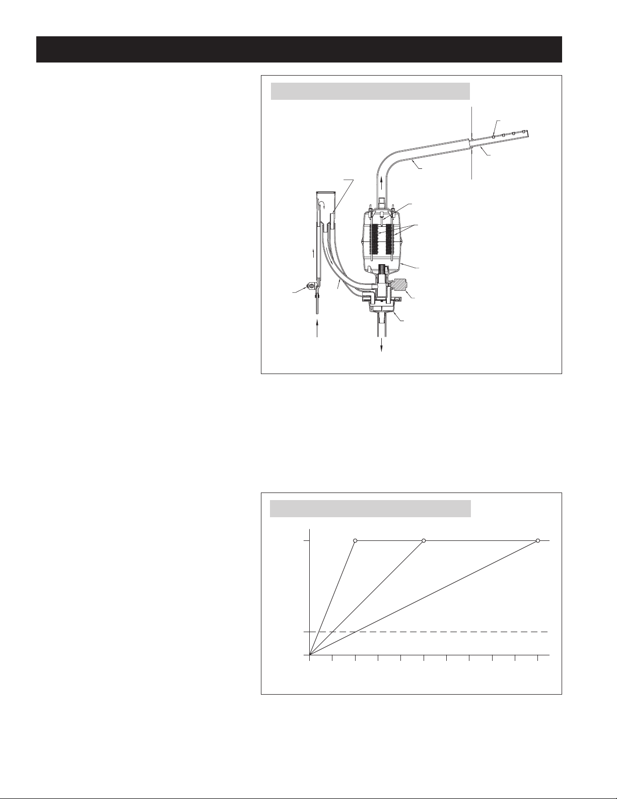
The Aprilaire® Steam Humidifier delivers humidity in the
form of steam to the conditioned space via the HVAC
system duct or Fan Pack. The humidifier generates steam
by energizing two electrodes that extend into a canister
of water. Current flowing between the electrodes causes
the water to boil, creating steam. Water is introduced to
the humidifier through a fill valve to a fill cup located in
the top of the cabinet. The fill cup serves as an overflow
reservoir and provides an air gap between the humidifier
and water source. The steam canister is filled from the
bottom. The canister is seated in a drain cup assembly
which includes a drain valve. The drain and fill valves
work together to maintain water level in the canister to
deliver the rated steam capacity based on the electrical
conductivity of the water and to temper drain water. See
Figure 1 for representation of fill and drain system and
canister.
To control the Steam Humidifier as part of the HVAC
system, the Model 62 Automatic Digital Humidifier Control
(ADHC) is installed to detect the RH level in the duct.
When the ADHC detects RH below the set point, and the
humidifier and HVAC system blower are operating, the
humidifier energizes the electrodes to provide steam.
Steam is delivered into the duct work via the steam hose
and through the dispersion tube. The dispersion tube is
fitted with opening called “Tubelets™”. The design of the dispersion tube and Tubelets distribute steam over a wide area in the duct and direct
any condensed moisture back into the steam hose. The blower activation function on the ADHC allows the control to turn on the HVAC system
blower to maintain the proper RH level even when the furnace or air handler is in stand-by mode. See ADHC installation manual.
FIGURE 1 – Fill and Drain System and Canister
Steam Hose
alve
Overflow
Fill
Supply
Water
Steam
Outlet
High Water Level Sensor
Electrodes
Canister
Drain Valve
Drain Cup
Tubelets
Dispersion T
in Duct
90-1522
Humidity can be distributed directly into the living space via the Fan Pack. When the Model 65 Manual Digital Humidistat detects RH below the
set point, the humidifier energizes the electrodes to provide steam via the steam manifold at the bottom of the Fan Pack. Steam is dispersed by
the fan located behind the grille above the steam manifold. The fan will operate for two minutes after the call for humidity ends, to disperse any
residual steam.
To provide precise control to the Modulating Steam
Humidifier, the Automatic Digital Modulating Control
FIGURE 2 – Humidifier Output for ADMC Signal
(ADMC) should be installed in the living space. The ADMC
will vary the Modulating Steam Humidifier output based
on the difference between set point and actual RH. The
100%
PROPORTIONAL BAND
ADMC sends a proportional signal to the Modulating
Steam Humidifier providing precise control of living space
humidity. See Figure 2 for steam humidifier output vs RH
demand. The ADMC can be used in place of the ADHC
and Manual Digital Humidistat to provide On/Off control
to the Steam Humidifier not equipped with the modulating
feature. See the ADMC installation and operating manual
for details.
HUMIDIFIER OUTPUT (%)
2% PROPORTIONAL BAND SETTING
20%
5% PROPORTIONAL BAND SETTING (DEFAULT)
10% PROPORTIONAL BAND SETTING
HUMIDIFIER OFF
-2% -5% -10%
RH DIFFERENCE FROM SETPOINT (%)
90-2008
4
Page 5
SPECIFICATIONS & DIMENSIONS
This humidifier is able to produce steam at various capacities depending on the voltage and current applied. The unit can be wired to use an
input voltage of 120, 208 or 240 Volts and input amperage can be set to 11.5 or 16.0 amps by changing a dip switch on the control circuit board
(see the Electrical Power Wiring & Shut Off Switch section on page 15). Configure the unit appropriately for the application (see Table 1 for
capacity specifications).
TABLE 1 – Humidifier Capacities and Recommended Home Sizes
2
*
Amperage Voltage
120V 11.5 2,500 sq ft 1,500 sq ft 1,000 sq ft
Maximum steam
capacity (gal/day)
Maximum recommended home size in ft
Tight Average Loose
11.5
208V 20.5
4,500 sq ft 2,500 sq ft 1,500 sq ft
240V 23.3
120V 16.0 3,500 sq ft 2,000 sq ft 1,500 sq ft
16.0
208V 30.0
6,000 sq ft 4,000 sq ft 2,500 sq ft
240V 34.6
* Assumes 8 ft ceiling height, adjust as necessary for higher ceilings. For homes with multiple furnaces/air handlers a humidifier should be installed on each.
Model 800 Shipping Weight: 28 lbs
Model 865 Shipping Weight: 39 lbs
Humidifier Operating Weight: 23 lbs**
** As minerals precipitate unit weight can increase to approximately 30 lb.
5
Page 6
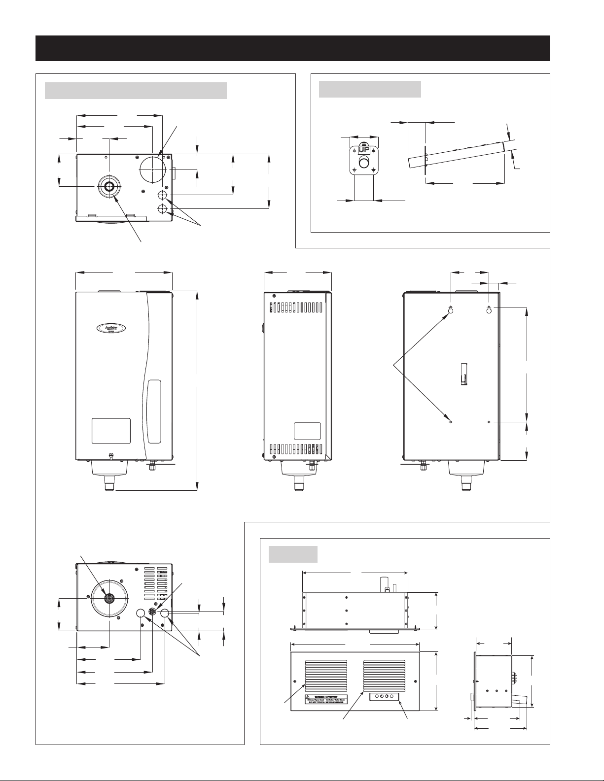
10-1/8
20-7/8
FRONT VIEW
3-3/8
7-7/8
8-7/8
3-3/8
1-5/8
4-1/4
5-3/4
Dispersion Outlet
Electrical Knockouts
Fill Cup
TOP VIEW
7-1/8
SIDE VIEW
1
4
4
12
BACK VIEW
Mounting
Holes
3-3/8
3-3/8
7-7/8
2
6-5/8
9-1/8
1-7/8
Water
Fill Line
Connection
Drain
BOTTOM VIEW
Electrical
Knockouts
3 sq
2 sq
1-3/4
8-1/4
1 dia
SPECIFICATIONS & DIMENSIONS (CONTINUED)
8
14
Fan
Inlet
Manifold
FIGURE 3 – Humidifier Dimensions (inches)
Steam Dispersion Tube
3 sq
90-1518
2 sq
1-3/4
1 dia
8-1/4
90-1518
6
Fan Pack
5
17-1/16
7-13/16
90-1554
Fan Outlet Steam Dispersion
3/8
4-3/4
6-7/
6-1/16
7-1/16
Page 7
SPECIFICATIONS & DIMENSIONS (CONTINUED)
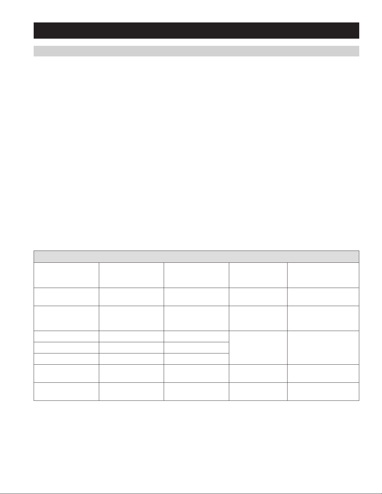
WATER QUALITY
Minerals that are naturally found in water cause the water to be electrically conductive. Water conductivity is measured in micro Siemens per
centimeter (uS/cm). Mineral content, also described as “water hardness” is usually measured in grains per gallon. Because of the variety of
minerals that are found in water, there is no direct correlation between water hardness and conductivity, but generally the higher the mineral
content, the higher the conductivity.
The Steam Humidifier is designed to operate on water with conductivity between 125 and 1,250 uS/cm. This correlates loosely with water with
hardness between 3 and 36 grains/gallon. Water that is considered “hard” and also softened water work well in the Steam Humidifier. The
humidifier will make steam when plumbed to low-conductivity water but it takes longer to reach nominal capacity.
With low conductivity water, it may take the Steam Humidifier one week or more of operation to reach rated capacity, especially
if it is wired to operate on 120 volts. When operating on 208/240 volts, the Steam Humidifier usually will reach nominal capacity
within a few hours, even with lower conductivity water.
As water in the canister boils and turns into steam, minerals are left behind. Minerals remaining in solution increase the conductivity of the
water. Minerals also deposit onto the submerged portions of the electrodes rendering those areas ineffective. As this occurs, the level of water
in the canister rises to expose uncoated electrode surface.
There are benefits and trade-offs to consider when the application allows a choice between hard and softened water:
Hard water: The benefit of hard water is less frequent draining and filling than with soft water, which results in better energy and water
efficiency and more consistent steam output. However, canister replacement could be more frequent with hard water, because mineral deposits
coat the electrodes. The harder the water, the more frequent the need for a new canister.
Softened water: The benefit of softened water is longer canister life (depending on water chemistry) than with hard water, because softened
water does not coat the electrodes nearly as much as hard water. However, softened water ions stay in solution to much higher concentrations
than hard water ions. This requires more frequent draining and filling, which results in lower energy efficiency, higher water consumption and
less consistent steam output.
TABLE 2 – Water Quality Guidelines
Conductivity (uS/cm)
of water connected to
humidifier
0-125 0-3 Naturally Soft
125-300 3-9 Naturally Soft Long start up time.
300-500 9-15 Slightly Hard
500-640 15-20 Moderately Hard
640-840 20-25 Hard
840-1250 25-36 Very Hard
above 1250 36 Extremely Hard
Estimated grains/gallon
(prior to any water
softening)
Hardness (prior to any
water softening)
Canister behavior Solution
Humidifier does not
function.
Optimal performance
range.
Shortened canister life
due to mineral build up.
Canister performance
degrades quickly.
Installation not
recommended.
Power with 208/240VAC,
use constant fan to decrease
time to reach full capacity.
Use either hard or softened
water.
Use softened water.
Installation not
recommended.
7
Page 8

INSTALLATION INSTRUCTIONS
Do not mount humidifier in a location where operating ambient temperatures exceed 104°F or where freezing temperatures
may occur.
CHOOSING A LOCATION
DISPERSION TUBE LOCATION
When choosing a location for the dispersion tube three things must be considered: Location in duct, elevation with respect to the humidifier, and
distance from humidifier to dispersion tube.
Duct Location and Absorption Distance
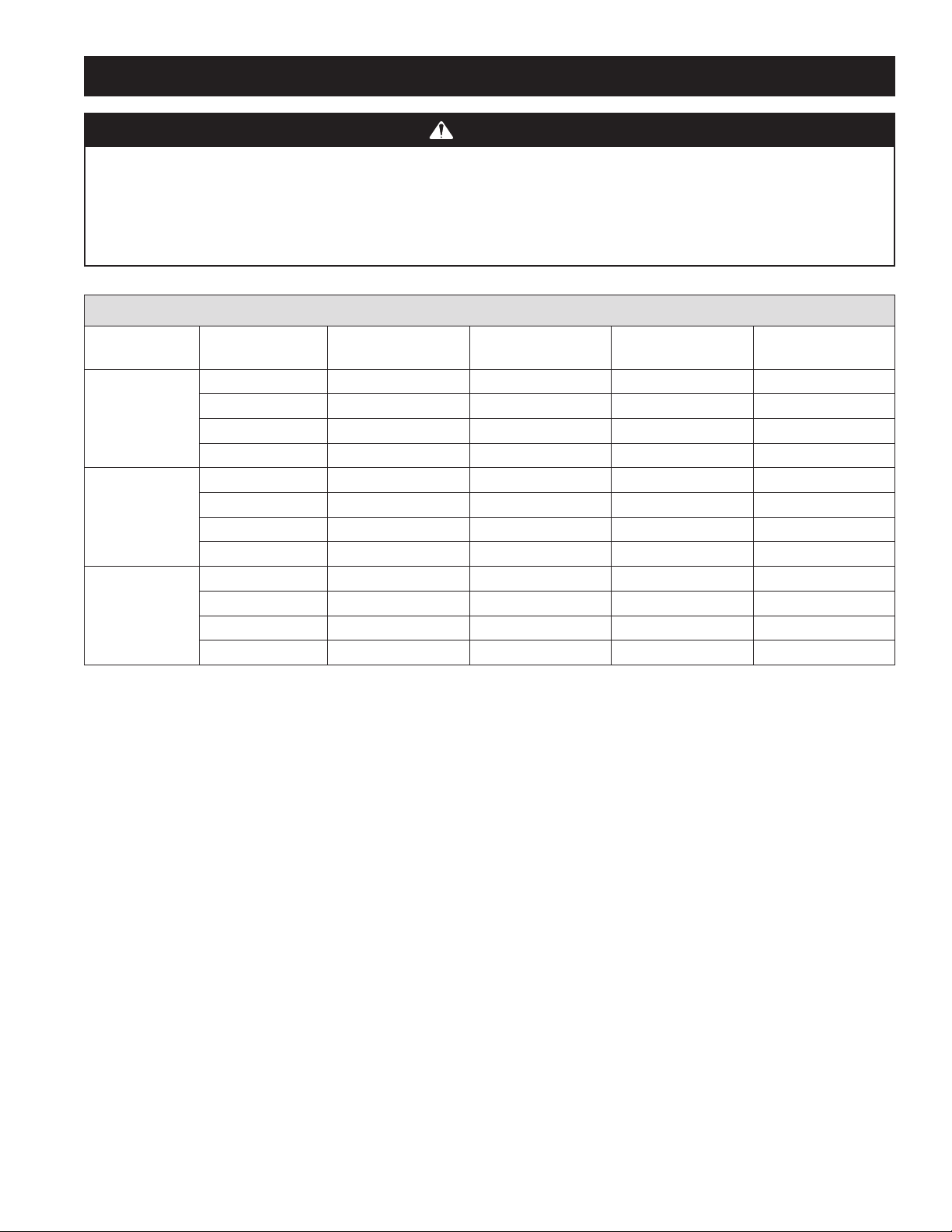
Absorption distance, the unobstructed straight line distance needed for steam to be fully absorbed, is dependent on air velocity, air temperature
and relative humidity in the duct. Determine absorption distance based on the lowest duct temperature, lowest air velocity and
highest humidity that the system will see. The dispersion tube must be located in a straight section of duct far enough upstream of any
obstructions or bends in the duct. Use Table 3 to determine the appropriate absorption distance.
Operation during AC calls is not recommended because of the potential for condensation in the ductwork. Configure controls to lock out the
humidifier during AC calls and use the blower activation feature to allow the humidifier to run with the blower only. Call Aprilaire Tech Support
at 1-800-334-6011 for additional information on steam absorption.
The dispersion tube must be mounted with the plate on a vertical surface with the tube angled up as shown in Figure 8. The steam tubelets
must face up regardless of the airflow direction in the duct. The plate is labeled “UP”to indicate proper orientation. On horizontal duct runs
install the dispersion tube low in the duct, on vertical runs center the tube on the duct.
If the dispersion tube is mounted on insulated ductwork, make sure insulation is not more than 2” thick at tube location to prevent insulation
from blocking first steam outlet.
Note: If dispersion tubes for two humidifiers are installed in one duct, double the dispersion distances. If three dispersion tubes are installed,
triple the dispersion distance. Position dispersion tubes so one does not discharge directly onto another.
8
Page 9
INSTALLATION INSTRUCTIONS (CONTINUED)
CAUTION
Each humidifier requires its own steam hose and dispersion tube. Do not connect steam hoses from more than one humidifier
together. Back-pressure from one humidifier can lower the water level in the canister in the other humidifier and cause
operational problems.
Do not install the dispersion tube in a duct with greater than 2 in. wg static pressure. High duct pressure can cause backpressure in the canister which can result in unstable unit operation.
TABLE 3 – Absorption Distance (Minimum distance from dispersion tube downstream to any obstruction or bend in duct)
Humidifier
Output (gal/day)
Up to 16.0
20.5 – 25.0
25.0 – 35.0
*Velocity in feet per minute = Duct airflow volume in cubic feet per minute / duct area in square feet.
Example: 1,200 cfm through 16” x 12” duct = 1,200/(12 x 16/144 sq. in./sq ft.) = 1,200/1.333 = 900 fpm
Airflow Velocity*
300 fpm 13” 19” 23” 30”
600 fpm 6” 10” 12” 18”
1200 fpm 3” 5” 6” 13”
1800 fpm 2” 3” 4” 10”
300 fpm 15” 23” 28” 45”
600 fpm 6” 12” 13” 26”
1200 fpm 5” 6” 7” 19”
1800 fpm 3” 4” 5” 16”
300 fpm 24” 31” 36” 60”
600 fpm 17” 22” 26” 48”
1200 fpm 12” 15” 18” 25”
1800 fpm 10” 13” 15” 20”
70°F & 30% RH
Setpoint
70°F & 45% RH
Setpoint
65°F & 45% RH
Setpoint
45°F & 45% RH
Setpoint
9
Page 10
INSTALLATION INSTRUCTIONS (CONTINUED)
for Steam Hose
FAN PACK LOCATION
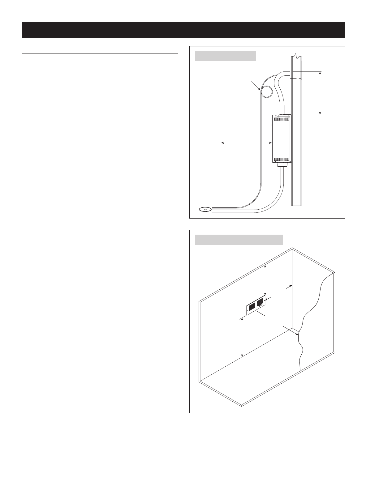
The Fan Pack must be located near the Steam Humidifier to minimize
the length of the steam hose. If the Fan Pack is mounted directly
above the humidifier, 16” is required for the steam hose to make
the bend. See Figure 4. NOTE: The loop in the condensate hose is
required to prevent steam from escaping into the drain.
Condensation running through the steam hose back into the canister
may cause a gurgling noise. Install Tee & Trap #4028 (included with
Model 865) as shown in Figure 10 to divert condensation to drain to
eliminate the gurgling noise.
Humidity behaves like a gas and under ideal conditions will expand to
fill the space. However, air movement due to drafts or as a result of
temperature stratification may cause uneven distribution of humidity
within the conditioned space. To ensure even RH distribution, install
system in a central location. If a central location is not available, it
may be necessary to install two systems. Two systems will provide
more even RH distribution than one.
To prevent condensation on surfaces and furnishings, install the fan
pack so the steam being discharged has enough room to be absorbed
into the air before encountering surfaces.
The following guidelines are for a 120V installation in which the unit
discharges into a space with 70°F air temperature and 40% RH.
FIGURE 4 – Side View
IMPORTANT:
Loop drain hose
below Fan Pack
to provide trap.
30" Recommended
for Service Access
NOTE:
See Figure 10 for drain
tee & trap installation
recommendations.
Drain
16" Minimum
90-1551
• Allow 4 feet of unobstructed space directly in front of the grille.
• Allow 2 feet on either side of the grille.
• Allow 1-1/2 feet above the grille.
See Figure 5.
If the Steam Humidifier operates on 240V, allow an additional foot of
space between the grille and any obstruction or surface.
If the room temperature is less that 70°F, allow an additional 6” to
each distance for every two degree drop in temperature.
If the RH set point is higher than 45%, allow an additional foot of
space between the grille and any obstruction or surface.
Warmer room air temperature and RH below 35% will reduce the
amount of unobstructed space required to absorb discharged steam,
but the distances provided are recommended minimums.
FIGURE 5 – Minimum Clearances
1-1/2 feet
minimum
to ceiling
2 feet
minimum to
side wall
4 feet
minimum to
objects in
front of grille
Maximize
90-1552
10
Page 11
INSTALLATION INSTRUCTIONS (CONTINUED)
Wall Studs on Center
Wall Stud
Tube
Tube
Terminals
Dispersion tube
Steam hose or pipe.
Insulate pipe with 1” fiberglass
Mount Fan Pack Housing
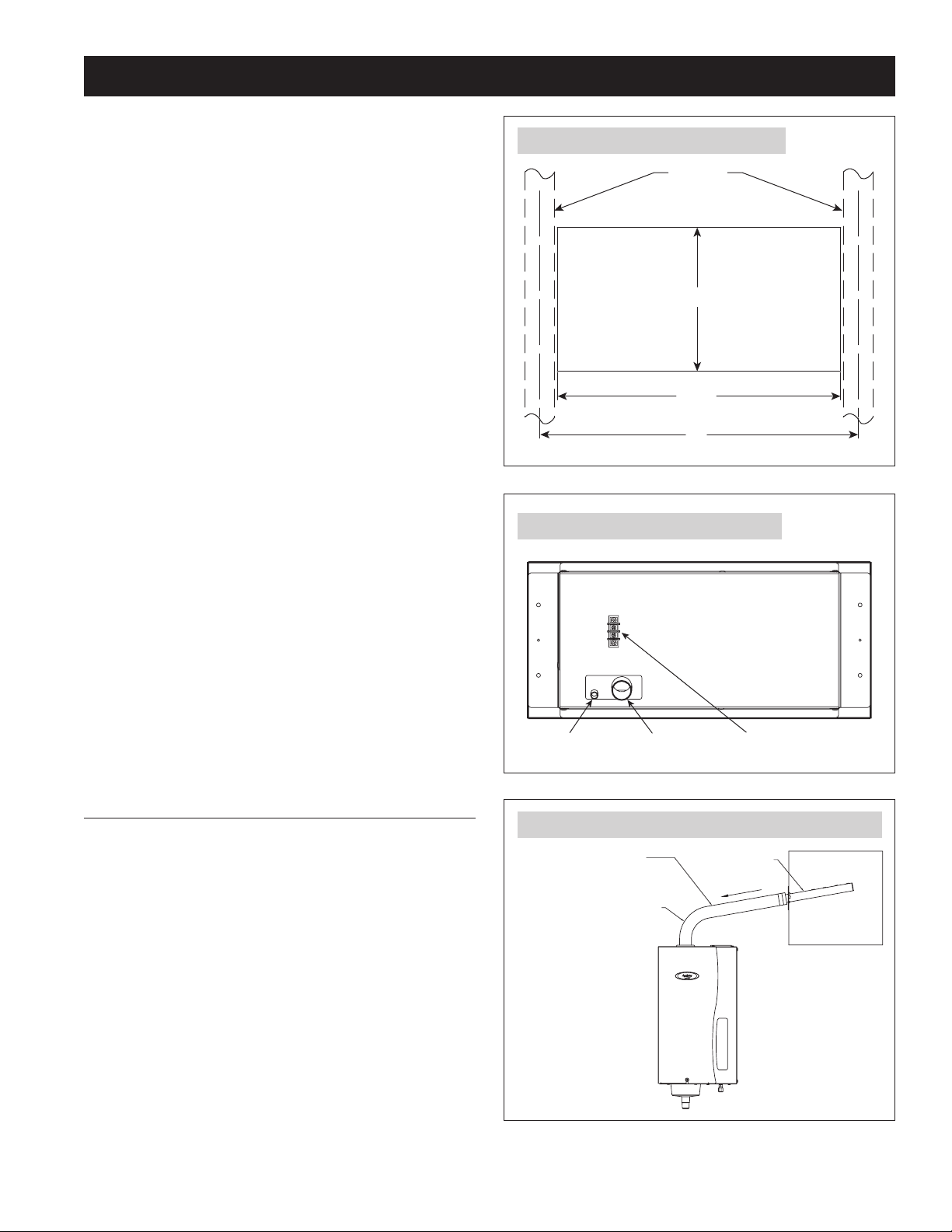
The Fan Pack installs between the studs of a standard 16” on-center
wall. Drywall on both sides of the wall must be removed for piping
and wiring the Fan Pack. To ensure proper operation, the Fan Pack
must be mounted level. Use the four 1-1/2” mounting screws
provided to attach the housing to the wall studs. See Figure 6.
Grille Installation
Use the two 5/8” screws to attach the Fan Pack grille to the fan
housing and drywall. See Figure 6. If painting the grille is desired,
see a painting professional for acceptable paint products for high
temperature (212°F), high humidity environments.
FIGURE 6 – Wall Opening and Mounting
Wall Cut-out
7-1/4"
Fan Pack Hose Connections
Connect the steam hose to the Fan Pack and use hose clamp to
secure. See Figure 7. If more than 6 feet is required, use insulated
hard pipe as shown in Figure 11. See Specifications & Dimensions
(page 5) for the affect on capacity. Ensure the trap is filled with water
before making steam connections.
Connect 3/8” ID condensate tubing to the Fan Pack and use wiretie to secure See Figure 7. To create a trap, make a 6” loop in the
condensate hose. See Figure 4. NOTE: The 6” loop must be located
below the Fan Pack connection. Do not kink the condensate hose. Use
wire ties to secure the loop. The loop is required to prevent steam
from escaping into the drain.
ELEVATION
The preferred location for the dispersion tube/fan pack is higher than
the humidifier so that the steam hose has a constant downward
slope of at least 2” per foot from the dispersion tube/fan pack to the
humidifier. If hard pipe is used, the slope can be 1/4” per foot. With the
constant downward slope, any condensation that forms in the steam
hose will drain back into the steam canister. See Figure 8.
14-1/4"
16"
FIGURE 7 – Fan Pack Hose Connections
Condensate
Steam
Electrical
FIGURE 8 – Dispersion Tube Mounted Above Humidifier
to reduce steam loss.
90° long sweep
or two 45° elbows
Pitch*
Duct
* Pitch steam hose down
from dispersion tube to
humidifier:
2"/ft (15%) minimum
when using steam hose.
1/4"/ft when using
hard pipe.
90-1550
90-1560
90-1521
11
Page 12
INSTALLATION INSTRUCTIONS (CONTINUED)
Drip tee installation for
piping over obstruction,
or if dispersion tube is
lower than humidifier
Reducing Coupling
To Steam
Dispersion
Hose Clamp
ube
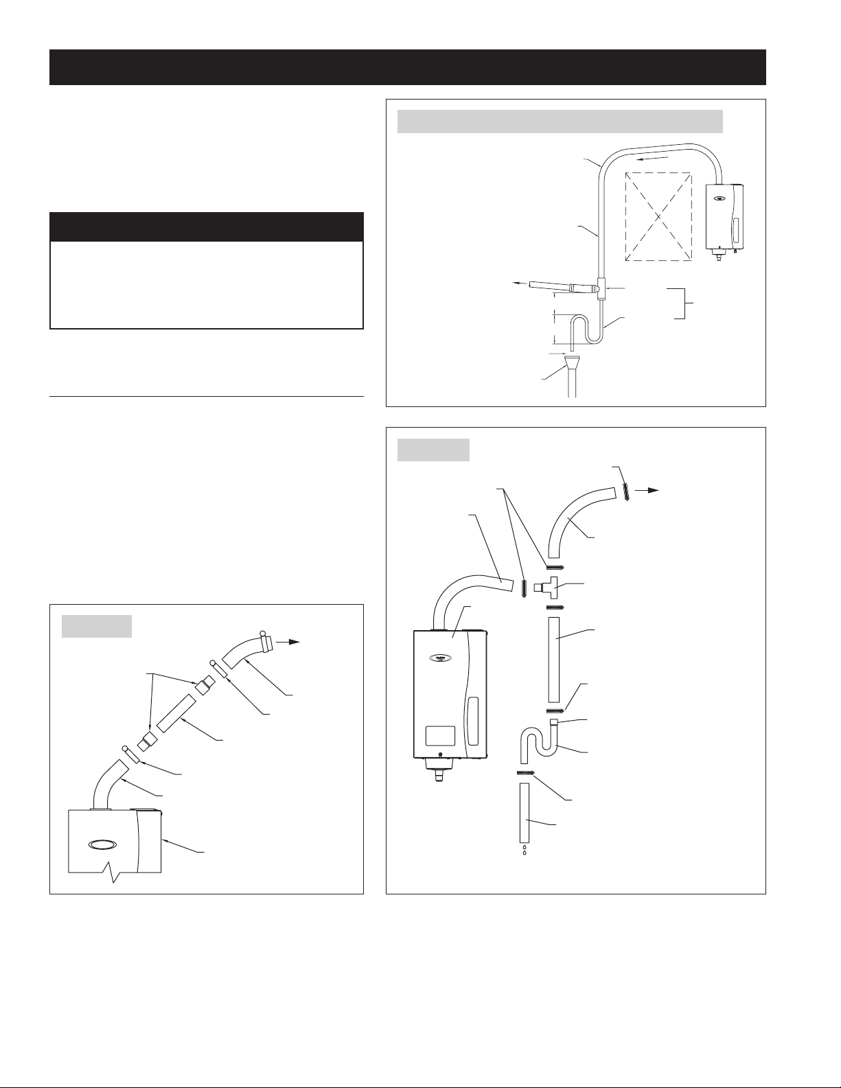
If the dispersion tube must be mounted below the humidifier or
if the steam hose needs to run up and over an obstruction, a drip
tee with drain trap, Part #4028, must be installed as shown in
Figure 9. When using a fan pack, install Part #4028 close to the
humidifier outlet to help prevent noise from gurgling as shown in
Figure 10.
FIGURE 9 – Dispersion Tube Mounted Below Humidifier
.
90° long
sweep or two
45° elbows
Pitch
NOTICE
CONTROL CONDENSATE FLOW AND COLLECTION.
Failure to follow steam hose recommendations in this
manual can result in reduced or erratic performance,
increased noise and condensate in the duct.
DISTANCE FROM HUMIDIFIER TO
DISPERSION TUBE/FAN PACK
The capacity of the humidifier is reduced by the length of
the steam hose or pipe due to condensation. The maximum
recommended length of steam hose is 6 feet. Use hard pipe
insulated with 1” fiberglass for lengths greater than 6 feet.
Table 4 provides humidifier capacity with various lengths of
steam hose and pipe. If 6-foot steam hose does not reach from
humidifier to dispersion tube, splice in 1” copper pipe using
3/4” x 1” reducing couplings as shown in Figure 11.
FIGURE 11
Tube or
3/4" x 1"
1" Copper Pipe
1-1/2" Hose Clamp
Steam Hose
Fan Pack
Steam Hose
1-1/2" Hose Clamp
90-1520
FIGURE 10
Steam Hose
1" I.D.
(Downward
Slope from
Humidifier
to Tee)
Insulate hard pipe to
reduce steam loss
To Dispersion
Tube/Fan Pack
1" air gap
Open drain required,
see note 1.
Hose Clamp
Steam
Humidifier
6" min
8" min
Obstruction
Drip tee
Drain trap
NOTES:
1. Refer to governing codes for
drain pipe size and materials.
2. Support steam hose so there
are no sags or low spots.
Steam Hose, 1" I.D.
(Downward Slope to Tee)
Tee
Assembly
Steam
Hose
1" I.D.
Hose
Clamp
Flared
End
Trap
Note: Prime with water
before using humidifier
Hose Clamp
Part #4028
To Steam
Dispersion T
or Fan Pack
#4028 KIT
CONTENTS:
Hose Clamps (5)
Trap (1)
Tee Assembly (1)
12
Humidifier
Drain Hose
7/8" I.D.
90-1527 90-1844
Page 13
INSTALLATION INSTRUCTIONS (CONTINUED)
TABLE 4 – Steam Humidifier Capacity in Gallons/Day
Steam
Hose or
Insulated
Pipe
Length
11.5 Amps 16.0 Amps 11.5 Amps 16.0 Amps 11.5 Amps 16.0 Amps
Steam
Hose
< 2 ft. 11.5 11.5 16.0 16.0 20.5 20.5 30.0 30.0 23.3 23.3 34.6 34.6
2 ft. 11 11 15.5 15.5 20 20 29 29.5 23 23 34 34
4 ft. 10 11 14.5 15.5 19 20 28 29.5 22 23 33 34
6 ft. 9 11 13.5 15 18 20 27 29 21 22 32 33
8 ft. 10 14 19 28 22 33
10 ft. 10 14 19 28 22 33
12 ft. 10 14 19 28 22 33
14 ft. 9 13 18 27 21 32
16 ft. 9 13 18 27 21 32
18 ft. 9 13 18 27 21 32
20 ft. 9 13 18 27 20 31
HUMIDIFIER LOCATION
Do not mount humidifier in a location where ambient
temperature exceeds 104°F or where freezing temperatures
may occur. Extreme temperatures may cause the humidifier to leak
which can damage furnishings or structure.
Mount humidifier in a location that allows access for servicing, and
clearance to remove front panel for replacing the canister and side
panel for access to the electrical components during installation.
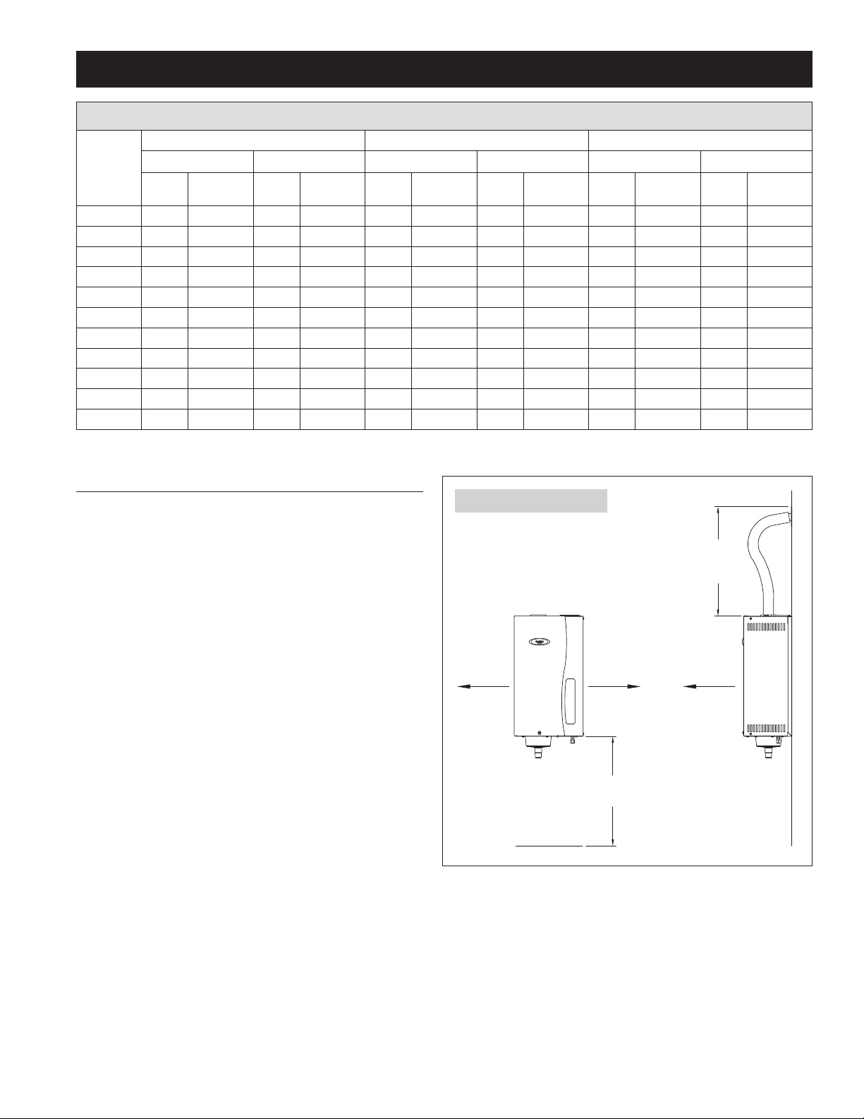
See Figure 12 for minimum clearances around humidifier.
The humidifier should be mounted as close to the dispersion
tube as possible. Table 4 shows how capacity is reduced as the
distance between the humidifier and dispersion tube increases. If
the humidifier is mounted on the duct directly below the dispersion
tube, allow space for a bend in the steam hose. Allow a minimum
of 2” of steam hose to extend straight out of the humidifier before
beginning any bends; this will help ensure a tight connection with
the top of the canister.
The humidifier can be mounted to a wood surface, or to sheet metal
ductwork if it is structurally stable. Do not mount humidifier to fiber
duct board. Sound isolation may be desired when mounting to sheet
metal ductwork.
120 Volts 208 Volts 240 Volts
Insulated
Pipe
Steam
Hose
Insulated
Pipe
Steam
Hose
Insulated
Pipe
Steam
Hose
Insulated
Pipe
Steam
Hose
Insulated
FIGURE 12 – Clearances
FRONT VIEW
16" for
4"
90-1519
Electrical
Access
16"
for Drain
Pipe
Steam
Hose
16" for
Steam
Hose
30" for
Service
Access
SIDE VIEW
Insulated
Pipe
The humidifier must be mounted to a vertical surface and must be
mounted level in the upright position.
13
Page 14

INSTALLATION INSTRUCTIONS (CONTINUED)
PREPARE HUMIDIFIER FOR MOUNTING
Unpack carton. Open front panel by removing screw and lifting panel up and away from humidifier. Disconnect three wires from top of canister
by pulling straight up. The two large wires are the electrode conductors. The smaller wire is connected to the high water level sensor. Remove
canister by pulling it up and out of drain assembly. Remove two screws on right side of humidifier and lift side panel off housing to expose
electrical compartment.
INSTALL STEAM DISPERSION TUBE/FAN PACK
Make sure steam dispersion tube/Fan Pack is mounted higher than the humidifier so that condensation that forms in the steam hose runs back
into the canister. If the dispersion tube/Fan Pack cannot be mounted higher than the humidifier or if the steam hose must extend up from the
humidifier then down to the dispersion tube due to an obstruction, a drip tee and drain trap system (Part #4028) must be installed as shown in
Figure 9.
Drill a 1-1/4” diameter hole in a vertical surface of the duct at the location chosen for the dispersion tube. Position the dispersion tube so it is
angled up, regardless of airflow direction. UP is stamped on the mounting bracket to aid in proper installation. Secure with four sheet metal
screws provided.
MOUNT HUMIDIFIER
Secure humidifier to sturdy wall using screws provided, or to sheet metal duct. Humidifier initially weighs 23 lbs with a full canister, but will
increase in weight over time due to the precipitation of minerals inside the canister. Make sure mounting system will support weight. If mounting
to stud frame wall, install two spanner boards to studs and fasten humidifier to spanner boards. Make sure humidifier is mounted plumb.
INSTALL STEAM HOSE
Six feet of steam hose is provided with the humidifier. If the steam hose must be cut, use a hacksaw. If additional length is required, use
1” O.D. metal or copper pipe. Do not use PVC pipe for steam line. Insulate pipe with 1” thick insulation rated for 212°F or higher to reduce
steam loss. See Table 4 for humidifier capacity at various lengths of steam hose and pipe.
Use the steam hose provided. Other hoses may have impurities which can cause foaming in the canister. Foaming can cause water level
inaccuracies, reduced steam production and water sputtering into the duct. When using pipe, remove all traces of residual materials used to
connect the pipe to prevent foaming.
Verify that the O-ring is in place in the groove in the drain assembly. Dampen the O-ring with water (DO NOT use oil, grease,or any lubricant
besides water), then reinsert the canister with the caution label positioned toward the front of the unit.
Attach steam hose to dispersion tube and then to top of canister using hose clamps provided. Make sure steam hose has a constant slope of at
least 2” per foot between the dispersion tube and the humidifier. Any and every low spot in the steam hose or pipe must have a drip tee and drain
trap. Fill drain trap with water before making final connections. Support the steam hose in multiple locations over its span to prevent sagging.
Attach and fully seat the electrode conductors (interchangeable) and the high water level sensor wire to the top of the canister.
SUPPLY WATER
Plumb the humidifier to cold, hard or softened water. Do not use hot water because unheated supply water is used to cool water
draining from the humidifier. Do not use demineralized or reverse osmosis water. For proper operation, supply water pressure must be between
25 psi and 120 psi. Hard or softened water may be used provided it has conductivity between 125 microS/cm and 1250 microS/cm. See Table 2.
Supply water piping must be free of oils, lubricants, solder flux and other contaminants, which can cause foaming.
Install the saddle valve according to the instructions printed on the bag. Run 1/4” copper tubing from the saddle valve to the humidifier. Connect
it to the fill valve. Double wrench to prevent leaking and damage to valve. Addition of a stainless steel braided water line can help reduce valve
noise.
Note: Adding an inline particulate filter can increase canister life in areas with high levels of suspended solids. DO NOT use filters that release
scale inhibitors, filters of this type can significantly decrease canister life.
14
Page 15

INSTALLATION INSTRUCTIONS (CONTINUED)
DRAIN LINE
Attach the 7/8” I.D. drain tubing provided to the drain assembly at the bottom of the humidifier. Secure with the hose clamp provided. Do not
over tighten.
Make sure the drain line has a constant downward slope from the humidifier to the drain and is not kinked or blocked.
If floor drain is not available, use condensate pump (Part #4856) to route water to a suitable drain. Provide at least 16 inches for of drain line
between the Steam Humidifier and the condensate pump.
Note: The humidifier uses cold water to temper drain water to less than 140°F.
ELECTRICAL POWER WIRING & SHUT-OFF SWITCH
CAUTION
Only qualified electrical personnel should perform field wiring procedures. Improper wiring or contact with energized circuits
can cause property damage or severe personal injury.
All wiring must be installed in accordance with all governing electrical codes and with the wiring diagram provided inside the front panel.
Do not loop power wiring.
Do not use aluminum wire.
A safety grounding system that meets all governing electrical codes is required. The ground connection must be made with solid metal to metal
connections. Ground wire must be the same size as the power wiring.
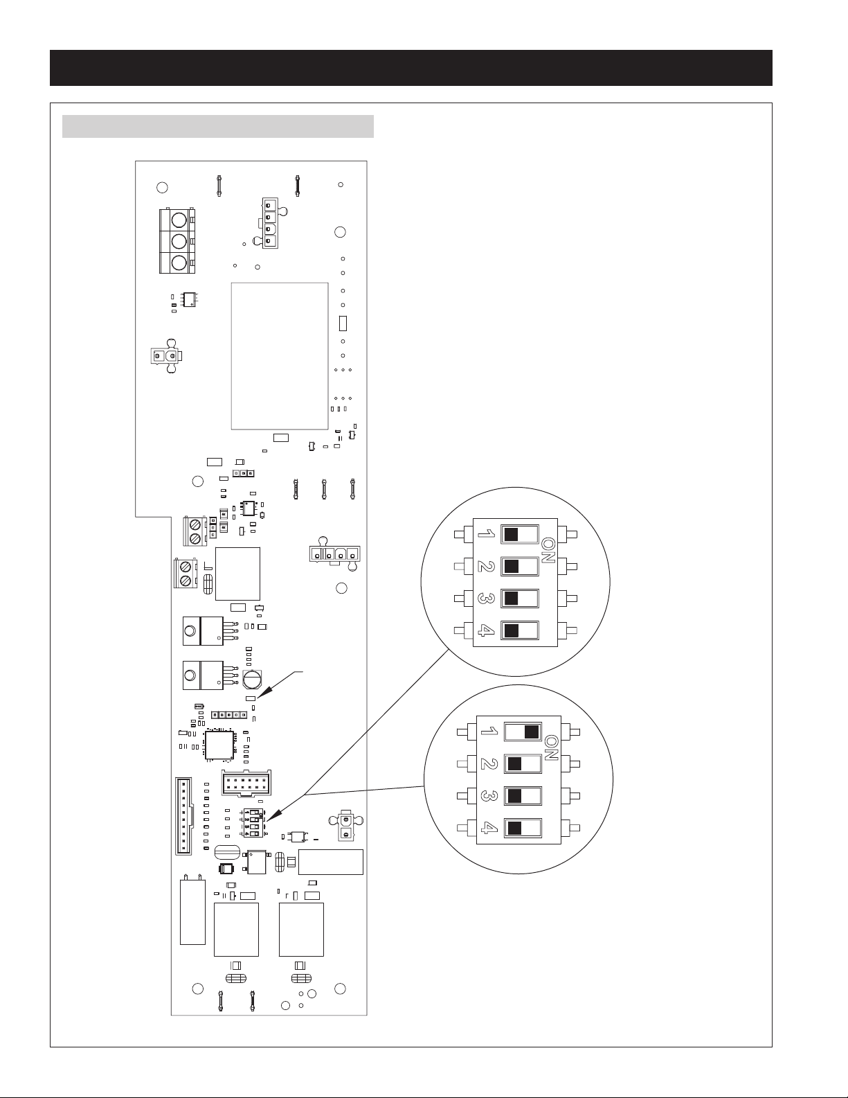
With factory settings, the Steam Humidifier draws 11.5 amps +/- 10%. Use a minimum 20 amp dedicated circuit when installing to operate at
11.5 amps. The Steam Humidifier can be set to draw 16.0 amps +/- 10% by repositioning dip switch #1 on the control circuit board (see Figure
13). When set to 16 amps, use a minimum 25 amp dedicated circuit. For both applications, size wire according to local codes.
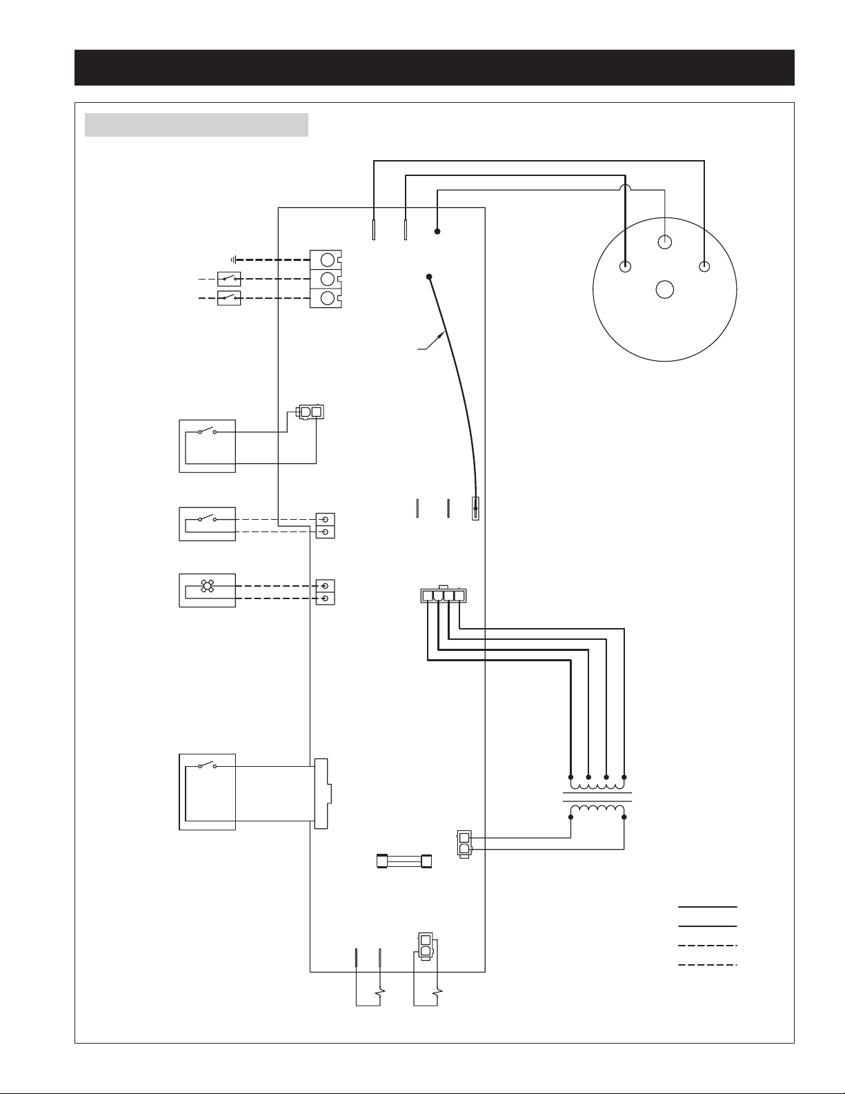
The Steam Humidifier is shipped from the factory wired for 240 VAC operation, but it can operate on 120, 208 or 240 VAC. If using 120V or
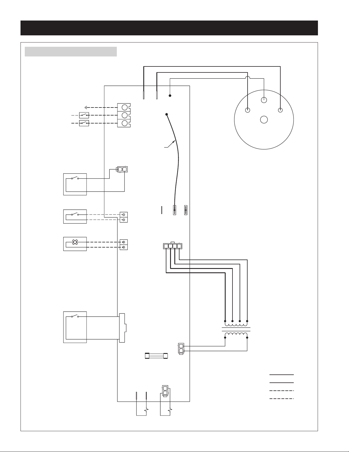
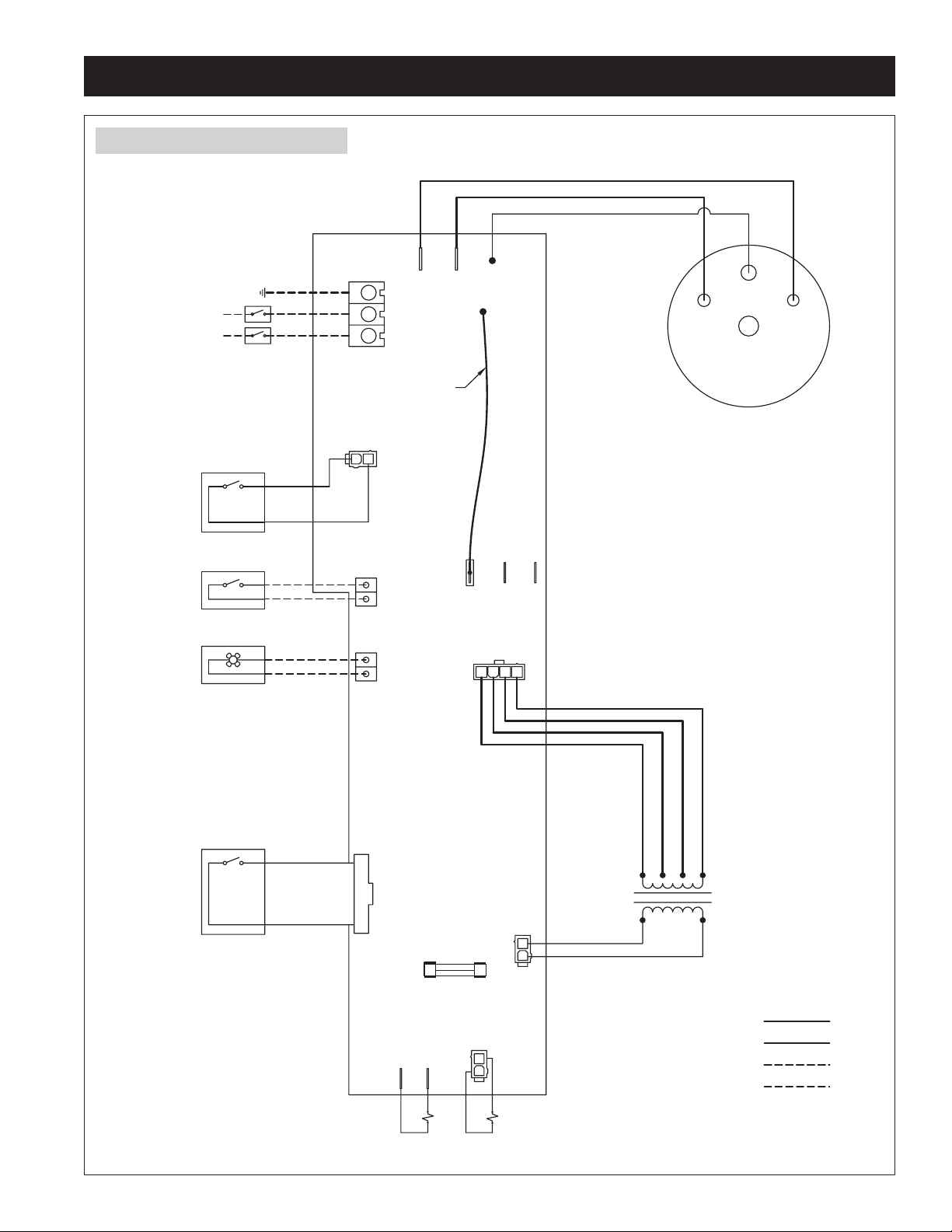
208V, move the black/white jumper wire to the proper tab on the control circuit board. See Figures 14, 15, 16.
WIRING INSTRUCTIONS
Install disconnect switch (not provided) between line power source and humidifier.
Knock-outs for power wiring and low voltage control circuit wiring are provided.
Connect power and ground wiring as shown in appropriate wiring diagram.
• 240 VAC – Figure 14
• 208 VAC – Figure 15
• 120 VAC – Figure 16
Do not run high voltage power lines over internal circuit boards.
15
Page 16
INSTALLATION INSTRUCTIONS (CONTINUED)
FIGURE 13 – Control Circuit Board with Dip Switches
LED D8
Factory setting for
11.5 AMP nominal
operation.
Slide Dip Switch #1
to “ON” position
for 16.0 AMP
nominal operation.
90-1959
16
Page 17
INSTALLATION INSTRUCTIONS (CONTINUED)
FIGURE 14 – 240 VAC Wiring Diagram
BLK
BLK
POWER
MAIN POWER BREAKER
(NOT PROVIDED)
GND
L2 / N
L1
DOOR SWITCH
ORANGE
TERMINAL
BLOCK
TRANSFORMER POWER
P7
J8
JUMPER WIRE
BLK/WHT
J10
J16
YEL
WATER LEVEL
PROBE
ELECTRODE
STEAM CANISTER
RESIDENTIAL STEAM HUMIDIFIER
IS SHIPPED FROM THE FACTORY
WIRED FOR 240 VOLTS.
ELECTRODE
HUMIDITY CONTROL
DRY
CONTACT
DISPLAY PA NEL
(PROVIDED)
FAN PACK
(OPTIONAL)
RIBBON CABLE
HUMIDISTAT
FAN PACK
J2
10
1
J5 J6
J13
120
VAC
SLOW BLOW FUSE
(5X20mm 5A)
CON1
BLK
YEL
J11
208
VAC
ORG
RED
BLK
WHT
P4
J14
240
VAC
P3
TRANSFORMER
BLUE
YEL
HIGH VOLTAGE WIRING
CONTROL CIRCUIT WIRING
HIGH VOLTAGE FIELD WIRING
LOW VOLTAGE FIELD WIRING
90-1903
DRAIN
VALV E
FILL
VALV E
17
Page 18
INSTALLATION INSTRUCTIONS (CONTINUED)
FIGURE 15 – 208 VAC Wiring Diagram
BLK
BLK
POWER
MAIN POWER BREAKER
L2 / N
DOOR SWITCH
HUMIDITY CONTROL
(PROVIDED)
DRY
CONTACT
(OPTIONAL)
(NOT PROVIDED)
GND
L1
ORANGE
FAN PACK
TERMINAL
BLOCK
TRANSFORMER POWER
P7
HUMIDISTAT
J8
JUMPER WIRE
J10
BLK/WHT
J13
120
VAC
J16
YEL
208
VAC
J11
J14
240
VAC
WATER LEVEL
PROBE
ELECTRODE
STEAM CANISTER
RESIDENTIAL STEAM HUMIDIFIER
IS SHIPPED FROM THE FACTORY
WIRED FOR 240 VOLTS. MOVE THE
JUMPER WIRE TO TERMINAL J11
TO OPERATE AT 208VAC.
ELECTRODE
DISPLAY PA NEL
RIBBON CABLE
FAN PACK
J2
10
1
SLOW BLOW FUSE
(5X20mm 5A)
J5 J6
BLK
CON1
YEL
YEL
WHT
P4
P3
ORG
RED
BLK
TRANSFORMER
BLUE
YEL
HIGH VOLTAGE WIRING
CONTROL CIRCUIT WIRING
HIGH VOLTAGE FIELD WIRING
LOW VOLTAGE FIELD WIRING
18
90-1904
DRAIN
VALV E
FILL
VALV E
Page 19
INSTALLATION INSTRUCTIONS (CONTINUED)
FIGURE 16 – 120 VAC Wiring Diagram
BLK
BLK
POWER
MAIN POWER BREAKER
L2 / N
DOOR SWITCH
HUMIDITY CONTROL
DRY
CONTACT
(NOT PROVIDED)
GND
L1
(PROVIDED)
FAN PACK
(OPTIONAL)
ORANGE
TERMINAL
BLOCK
TRANSFORMER POWER
P7
HUMIDISTAT
J8
JUMPER WIRE
BLK/WHT
J10
J13
120
VAC
J16
YEL
J11
208
VAC
J14
240
VAC
WATER LEVEL
PROBE
ELECTRODE
STEAM CANISTER
RESIDENTIAL STEAM HUMIDIFIER
IS SHIPPED FROM THE FACTORY
WIRED FOR 240 VOLTS. MOVE THE
JUMPER WIRE TO TERMINAL J13
TO OPERATE AT 120VAC.
ELECTRODE
DISPLAY PA NEL
RIBBON CABLE
FAN PACK
J2
10
1
SLOW BLOW FUSE
(5X20mm 5A)
J5 J6
BLK
CON1
YEL
ORG
RED
BLK
WHT
P4
P3
TRANSFORMER
BLUE
YEL
HIGH VOLTAGE WIRING
CONTROL CIRCUIT WIRING
HIGH VOLTAGE FIELD WIRING
LOW VOLTAGE FIELD WIRING
90-1905
DRAIN
VALV E
FILL
VALV E
19
Page 20
INSTALLATION INSTRUCTIONS (CONTINUED)
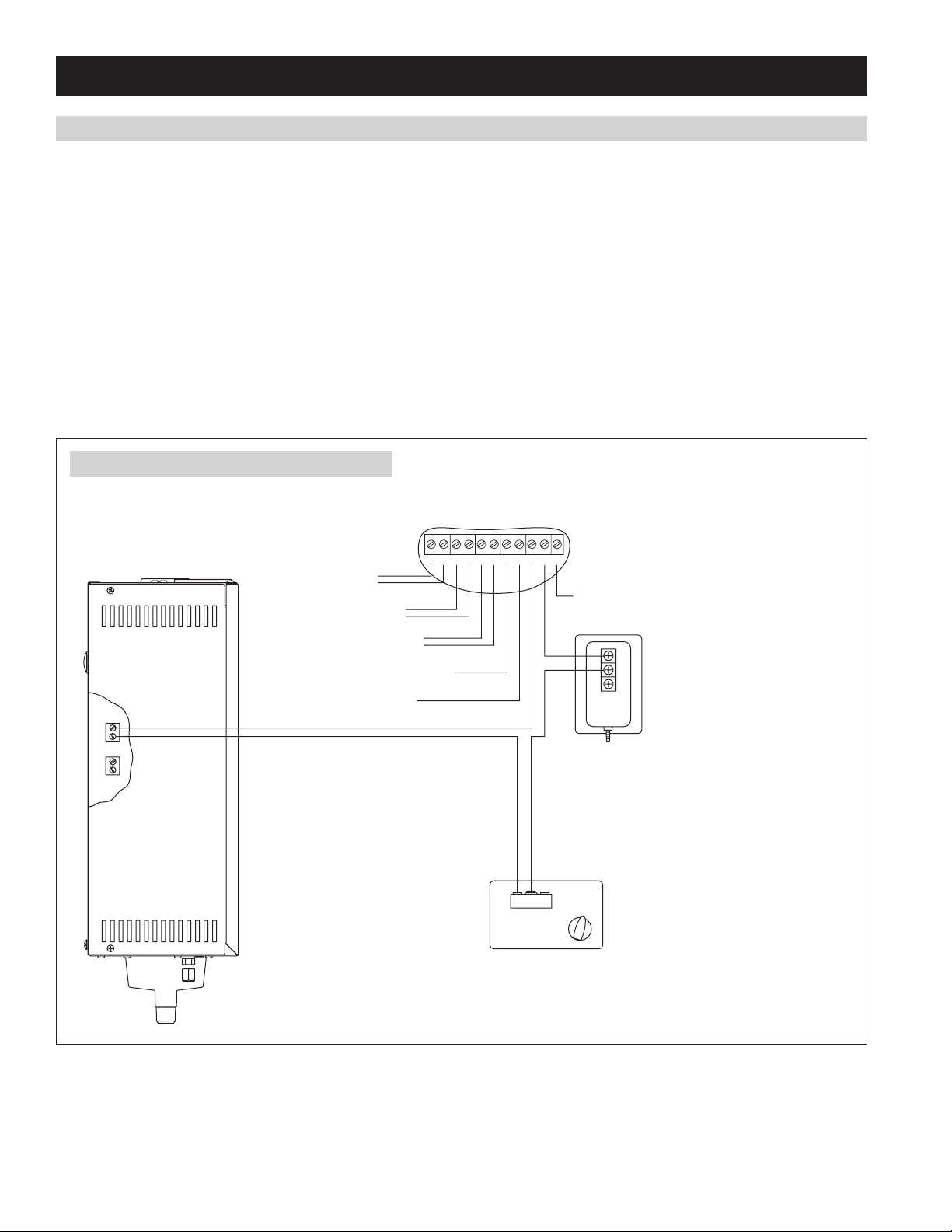
AUTOMATIC DIGITAL CONTROL AND ACCESSORY WIRING (MODEL 800)
The control circuit operates on 24VAC.
The ADHC (Automatic Digital Humidifier Control) Model 62 must be mounted in the return air duct at least 6” upstream of any fresh air intake
ducts or sources of moisture and at least 12” upstream of the steam dispersion tube if it is mounted in the return. Follow instructions provided
with the control. Connect “H” terminals on ADHC to “HUMIDISTAT” terminals on humidifier circuit board. The “H” terminals on the Model 62
provide a dry contact switch to energize the humidifier.
If the application requires a wall-mounted humidistat in the conditioned space, use Manual Humidistat Part #4655, Digital Manual Humidistat
Part #65, Automatic Digital Modulating Humidistat Part #63 or any Aprilaire thermostat with integrated humidifier control functionality. Use
Blower Activation Relay Part #4851 with Aprilaire Manual and Digital Manual Humidistats in order to allow the humidifier to turn on the HVAC
system blower when humidity is required.
If protection from over-humidification is desired, install optional high humidity limit switch Part #4594 at least 4 feet downstream of the
dispersion tube. If airflow verification is desired, install optional airflow proving switch Part #4592 in duct. The high humidity limit switch and the
airflow proving switch are wired in series with the ADHC (humidistat) circuit. See Figure 17.
FIGURE 17 – Steam Humidifier Accessory Wiring
MODEL 62 DIGITAL HUMIDIFIER CONTROL
24V TERMINALS
24 VAC from HVAC
HGf RCAB ODT GWH
Equipment “R” & “C”
Communication with
Fan Signal to HVAC Equipment
Aprilaire 8570 Thermostat
Outdoor Temperature Sensor
C
Heat Signal from HVAC Equipment
NO
NC
Fan Signal from Thermostat
OPTIONAL:
FAN PACK HUMIDISTAT
AIR FLOW PROVING SWITCH #4592
Connect 1/4" plastic tubing from H (High) side
of proving switch to the airflow sensing probe
located 1.5 duct diameters downstream of
blower. Leave L (Low) side open to amosphere.
C
NC
NO
OPTIONAL:
HIGH HUMIDITY LIMIT SWITCH #4594
Switch breaks C to NC connection when
measured RH is above setpoint RH.
90-1544
20
Page 21
INSTALLATION INSTRUCTIONS (CONTINUED)
ap Connectors
Aprilaire Steam Humidifier
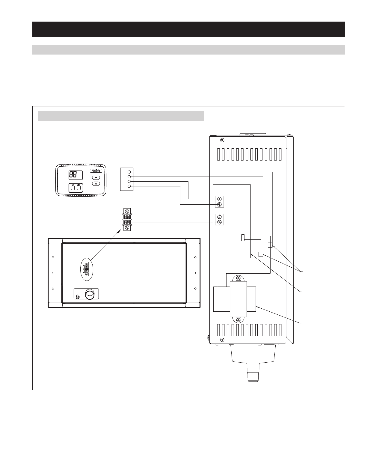
MANUAL DIGITAL HUMIDISTAT AND FAN PACK WIRING (MODEL 865)
Mount the Digital Manual Humidistat in the area to be humidified according to installation instructions included with control. Install the
humidistat in the same room or area as the Fan Pack discharge, but at least ten feet away. Wire the Digital Manual Humidistat to the Steam
Humidifier using standard 24 volt thermostat wire. See Figure 18.
Disconnect all power to Steam Humidifier before wiring the Fan Pack terminals to the FAN PACK terminals on the Steam Humidifier. Use
standard 24 volt thermostat wire. See Figure 18.
FIGURE 18 – Wiring Diagram for Manual Humidistat and Fan Pack
Model 65 Digital Control
%
SET
OFFON
*
Steam Humidifier Fan Pack
C
24VAC
R
H
H
24VAC
WIRE – 18 Awg acceptable for 24 VAC application.
YELLOW
FAN PA CK HUMIDISTAT
BLUE
P4
T
Circuit Board
Transformer
90-1662
21
Page 22
INSTALLATION INSTRUCTIONS (CONTINUED)
#
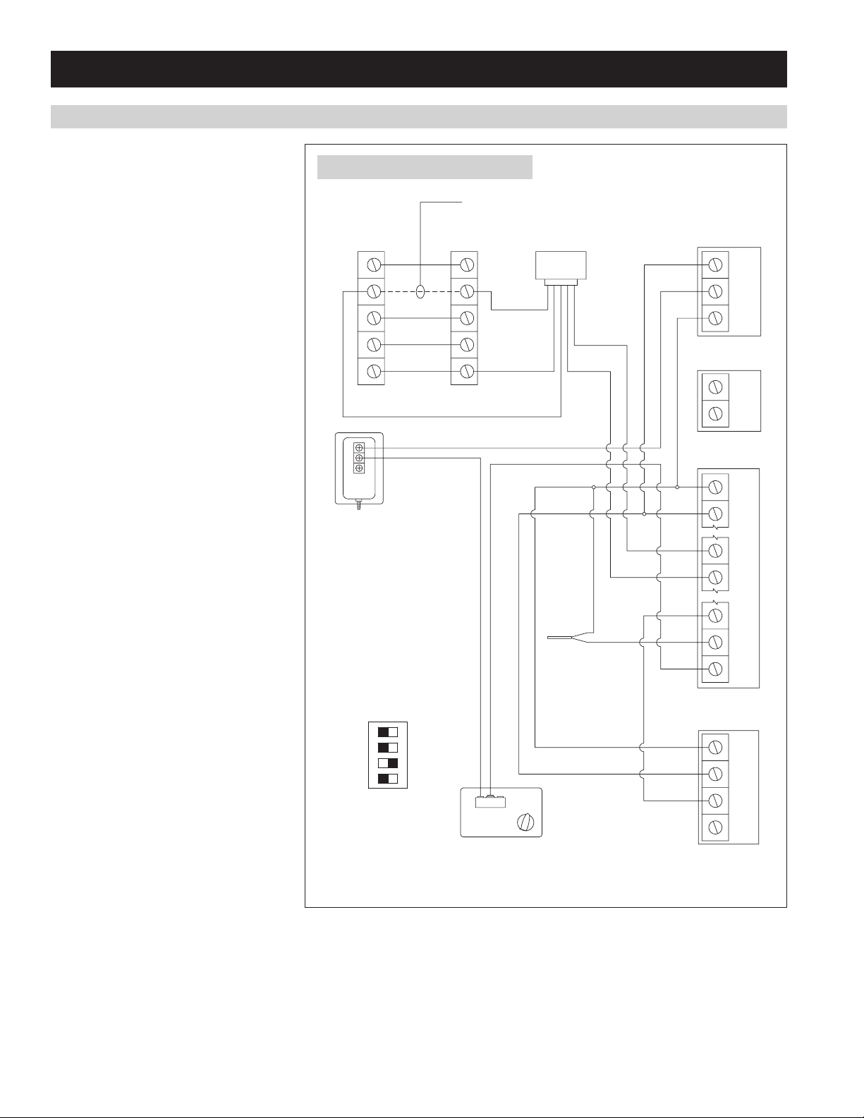
AUTOMATIC DIGITAL MODULATING CONTROL WIRING (MODEL 801 OR 866)
The Automatic Digital Humidifier Control
(ADMC) that ships with Model 63 and Model
5558 must be mounted on an interior wall in
the living space. Follow instructions provided
with the control.
If the ADMC cannot be mounted in the
living space, the duct humidity sensor can
be used as the primary humidity sensor and
the ADMC can be installed in a convenient
location. Install the duct humidity sensor in
the supply duct at least 6” upstream of any
fresh air intake ducts or sources of moisture
and at least 12” upstream of the steam
dispersion tube. Configure the ADMC to use
the duct sensor as primary humidity sensor.
See Program Mode Step #17 in the ADMC
installation manual.
If protection from over-humidification is
desired, install the duct humidity sensor in
the supply duct at least 4 feet downstream
of the dispersion tube. Configure the ADMC
to use the duct sensor as a high humidity
limit sensor. See Program Mode Step #17
in the ADMC installation manual. The ADMC
must be installed in the living space. See
Determine Location For Control section of
the ADMC installation manual.
If airflow verification is desired, install
optional airflow proving switch Part #4592
in duct and wire in series with the ADMC
humidistat circuit. See Figure 19.
FIGURE 19 – ADMC with Model 801
REMOVE
THERMOSTAT FURNACE
Y
G
W
C
R
BLU (NC)
C
NO
NC
OPTIONAL:
AIR FLOW PROVING SWITCH
4592
Connect 1/4" plastic tubing from
H (High) side of proving switch
to the airflow sensing probe
located 1.5 duct diameters
downstream of blower. Leave L
(Low) side open to atmosphere.
MODULATING
STEAM HUMIDIFIER
DIP SWITCH POSITION
ON
1
2
3
4
Y
G
W
C
R
YLW (C)
ORG (NO)
C
NC
NO
BLOWER
ACTIVATION
RELAY
4851
WHT / BLU
ODT
801
HUMIDISTAT
TERMINAL
24
IN
GND
WHT / YLW
FAN PACK
ADMC
1
2
7
8
12
13
14
(OPTIONAL)
DUCT SENSOR
1
2
3
NOTE: PLACE ADMC
JUMPER J2 IN THE LEFT
POSITION (POWERED).
22
OPTIONAL:
HIGH HUMIDITY LIMIT SWITCH #4594
Switch breaks C to NC connection when
measured RH is above setpoint RH.
4
90-1992
Page 23
INSTALLATION INSTRUCTIONS (CONTINUED)
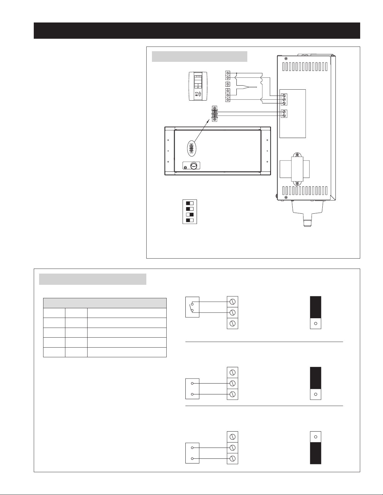
When the Modulating Steam Humidifier is
installed with the Fan Pack, wire the ADMC as
shown in Figure 20.
The Aprilaire Automatic Digital Modulating
Control is the recommended humidity
controller for the Model 801 and Model 866
Modulating Steam Humidifier. However, the
Modulating Steam Humidifier can accept a
number of different control signals. If using a
third party control, configure the Modulating
Steam Humidifier internal controller for the
third party control signal. See Figure 21 for
configuration options.
FIGURE 20 – ADMC with Model 866
STEAM HUMIDIFIER
DIP SWITCH POSITION
ADMC
%RH
36.
7
STEAM HUMIDIFIER FAN PACK
ON
1
2
3
4
MODULATING
12
13
14
24VAC
1
2
6
ODT
+24V
IN
GND
FAN PACK
APRILAIRE MODULATING
STEAM HUMIDIFIER
FIGURE 21 – Third Party Control Signals
CONTROL DIP SWITCH SETTINGS
DIP2 DIP3 HUMIDISTAT SIGNAL TYPE
OFF OFF ON / OFF
ON OFF 0-20 VDC
OFF ON 0-10 VDC or 0-20 mA
ON ON 2-10 VDC or 4-20 mA
WIRE – 18 AWG ACCEPTABLE FOR 24 VAC APPLICATION.
ON / OFF
HUMIDISTAT
MODULATING STEAM HUMIDIFIER
HUMIDISTAT TERMINAL
+24V
IN
GND
RECOMMEND USING BLOWER ACTIVATION RELAY PART # 4851
0-10 VDC, 0-20 VDC OR 2-10 VDC
MODULATING STEAM HUMIDIFIER
HUMIDISTAT TERMINAL
+24V
+
-
IN
GND
0-20 MA OR 4-10 MA
MODULATING STEAM HUMIDIFIER
HUMIDISTAT TERMINAL
+24V
+
-
IN
GND
90-1995
P6
1
2
3
P6
1
2
3
P6
1
2
3
90-1993
23
Page 24
START-UP PROCEDURE
1. Once the supply water, drain, steam hose, electrical power and control wiring connections are complete, make sure canister is fully seated
into drain valve and three wire connectors on top of canister are secure. (High water probe wire and two interchangeable electrode wires.)
2. Attach side panel and front door.
3. Open saddle valve allowing water to flow to humidifier. Check for leaks.
4. Turn Automatic Digital Control knob to OFF.
5. Close main power switch energizing humidifier.
6. Press On/Off button on humidifier. The On/Off light will illuminate green.
7. Make sure the HVAC blower is operating and adjust the ADHC dial up to initiate a call for humidity. If installed with a Fan Pack, turn On the
Model 65 Digital Manual Humidistat. Adjust the humidity set point with the up and down arrows.
Note: The ADHC can be placed into TEST mode to force a call for humidity but this only lasts for one minute.
The Steam light will illuminate green indicating a call for humidity and the Fill light will illuminate green indicating the fill valve is open
allowing the canister to fill. You should also hear the water flowing. If water flows down drain while humidifier is filling, check for
kinks or obstructions in the fill hose or fill cup and make sure the O-ring in the drain valve is properly seated in the groove and
not damaged or deformed.
8. Once the Fill light turns off, to verify that the humidifier will drain properly, press the On/Off button to turn humidifier off. You may hear the
fill valve open allowing cold water to flow into the canister to cool the water in the canister. The Drain light will flash green for 15 seconds
then turn green for four minutes while the canister drains. Once the Drain light turns off, the drain cycle is complete.
9. Set ADHC to proper level.
10. Press On/Off button to turn humidifier on.
11. If installed with a Fan Pack, ensure the Fan Pack fan operates.
12. Ensure the steam outlet of the Fan pack is not blocked.
CAUTION
The front of the Fan Pack will be hot. Steam may not always be visible.
Do not touch the front of the Fan Pack or place hand in front of the steam discharge manifold.
24
Page 25

OPERATING MODES
When the humidifier is powered and turned on, the “On/Off” light is illuminated green.
During fill cycles, the “Fill” light illuminates green.
When the humidifier is turned on, any time the Humidifier Control sends a call for humidity, the Steam light illuminates green.
Any time the drain valve is activated, the “Drain” light illuminates green.
During initial start up with a new canister, the humidifier may run through a series of fill/drain cycles until the conductivity of the water is in
a range that allows the humidifier to generate steam at the rated capacity. If the conductivity of the water is low, it may take a week or more
for the humidifier to generate steam at the rated capacity. The rated capacity is achieved when the humidifier is detecting a nominal current
of either 11.5 or 16.0 amps between the electrodes. If the humidifier has not reached capacity after 168 hours of operation, the Steam light
will illuminate yellow on a call for humidity. The humidifier will continue to operate with a yellow Steam light, and may satisfy the humidity
requirements. Once rated capacity is reached, the Steam light will illuminate green.
The internal controller adjusts water level in the canister to maintain the nominal current between the electrodes. As minerals build up on the
electrodes, their effectiveness decreases, so the controller will increase the water level to submerge more of the electrode surface. When the
water has reached the high level probe in the canister and the internal controller no longer detects nominal current, the Service light will flash
red indicating that the canister needs to be replaced.
If the humidifier attempts to drain the canister and cannot, the drain and fill valves will pulse on & off for four seconds to dislodge minerals
which may be blocking the drain valve ports. The Drain and Fill lights will flash on & off when this occurs.
Any time power is disconnected or humidifier is turned off, the internal timer for start-up and drain cycles is reset.
If the humidifier has operated 168 hours without a drain cycle, the drain valve will open and drain the canister. Normal operation will continue.
If the humidifier is operating and a power failure occurs, once power is restored, the “On/Off” light will flash green for one minute, then the
humidifier will turn on.
END OF SEASON/PERIOD OF INACTIVITY SHUT-DOWN
The humidifier does not need to be turned off at the end of the humidification season. If 72 hours elapses without receiving a call for humidity,
the canister will automatically drain. The Drain light will remain lit for 24 hours. This may also occur during periods of inactivity during the
humidification season. The humidifier will resume normal operation when a call for humidity is made.
25
Page 26
SHUT DOWN PROCEDURE
To turn humidifier off, push ON/OFF button once. Humidifier will begin its four-minute drain cycle. Fill valve will open to temper drain water. The
Drain light will flash green for 15 seconds then turn green for four minutes while the canister drains. Once the Drain light turns off, the drain
cycle is complete and the humidifier is off.
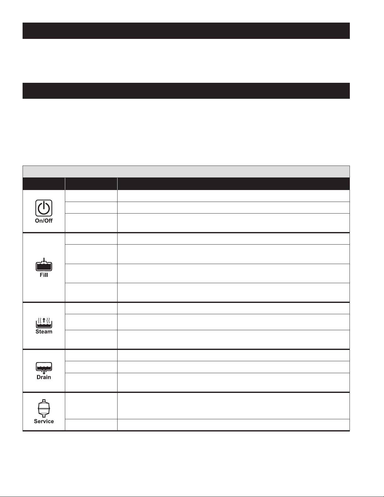
DISPLAY PANEL
Green lights indicate normal operation.
Yellow Steam light indicates humidifier is operating at less than rated capacity.
Flashing red Service light indicates canister is near the end of its life and should be replaced if the humidity in the space cannot be maintained.
Solid red lights indicate humidifier has shut down and requires service.
Disconnecting power to humidifier resets internal timers.
TABLE 5 – Display Panel
Indicator Light Function
Off
Solid green
Flashing Green
Off
Solid Green
Flashing Green
Solid Red
Off
Solid Green
Solid Yellow
Off
Solid Green
Humidifier is turned off or power is disconnected.
Humidifier is turned on.
Humidifier is preparing to turn on. Occurs if power to humidifier was turned off when humidifier
was on. Humidifier turns on after light flashes for one minute.
Fill valve not energized.
Fill valve is energized, filling or replenishing canister with water. (During drain cycle when fill valve
is open allowing cold water into canister to temper drain water, the fill light does not illuminate.)
Fill and Drain Valves are pulsing to dislodge mineral deposits from drain. Flashes 10 times in 4
seconds. Occurs if high water probe detects water during drain cycle.
Humidifier cannot fill canister. Humidifier stops operating. Occurs after fill valve has been energized
for 40 minutes and high water probe does not detect water.
Humidifier is not producing steam
Humidifier is turned on and receiving a call for humidity from the control.
Humidifier is producing steam but at less than the rated capacity. Occurs if humidifier has operated
for 168 hours and has not reached nominal current.
Drain valve not energized.
Drain valve is energized, allowing water to drain from canister.
Flashing Green
Flashing Red
Solid Red
26
Humidifier is preparing to drain. Flashes for 15 seconds indicating fill valve is open allowing cold
water into canister.
Canister has reached end of life. Humidifier continues to operate but at reduced capacity. Occurs
after humidifier has operated for 168 hours plus another 24 hours at less than 75% of the maximum
operating current level between electrodes.
Humidifier is not operating and requires service.
Page 27

MAINTENANCE
NOTICE
• Allow humidier to drain and disconnect power before servicing.
• Service should be performed by a qualied HVAC technician.
Inspect humidifier when servicing.
• Check for loose electrode connections on the canister. Replace electrode wires if connection is loose.
• Check system operation and inspect all plumbing connections and piping for signs of cracks or leaks.
• Inspect drain line to make sure it is not blocked and has constant downward slope. Clean or replace if necessary.
• Inspect steam hose to make sure it has no low spots and has constant upward slope from humidifier to dispersion tube in duct. If dispersion
tube is mounted below humidifier, inspect drip tee and drain.
TO REPLACE THE CANISTER
1. Turn humidifier off.
2. Unit will go through drain cycle – 4 mins – and turn off when
complete.
3. Disconnect main electrical power to humidifier at the circuit
breaker.
4. Allow the unit to cool.
5. Remove front door.
6. Remove electrode wires, high water probe wire, steam hose and
canister.
7. Remove O-ring from groove in drain assembly using a small screw
driver.
8. Insect drain assembly and remove any debris – see TO CLEAN
THE DRAIN VALVE.
9. Insert new O-ring into groove in drain assembly. (O-ring is
provided with Model 80 canister.) Dampen O-ring with water
before inserting canister. Do not use oil, grease, or any lubricant
besides water.
10. Make sure strainer is inserted into bottom of new canister.
11. Insert canister into drain assembly. Position canister with label
facing outward.
12. Reconnect steam hose and wires ensuring wires are fully seated.
13. Replace front door.
14. Restore electrical power to humidifier.
15. Turn humidifier On and verify green On/Off light is illuminated.
16. See Start-up procedure.
17. Check for leaks.
TO CLEAN THE DRAIN VALVE
1. Turn humidifier off.
2. Unit will go through drain cycle – 4 mins – and turn off when
complete.
3. Disconnect main electrical power to humidifier at the circuit breaker.
4. Allow the unit to cool.
5. Remove front door.
6. Remove electrode wires, high water probe wire, steam hose and
canister.
7. With your finger swirl the fluid/precipitate mixture in the bottom of
the drain valve reservoir.
8. Using a sponge or paper towels soak up the water in the reservoir,
if necessary use a wet/dry vacuum to remove residue.
9. Clean the inside of the drain port (where coil projects out) by gently
swabbing with a bent cotton swab or other soft implement.
10. Rinse the drain valve reservoir with clean water and vacuum as
necessary.
11. Replace canister, reconnect steam hose and wires ensuring wires
are fully seated.
12. Replace front door.
13. Restore electrical power to humidifier.
14. Turn humidifier On and verify green On/Off light is illuminated.
15. See Start-up procedure.
16. Check for leaks.
TO SERVICE THE FILL VALVE
If water flow from the valve is restricted, disconnect the inlet fitting
and remove in line strainer from the inlet port using a small screw.
Clean or replace strainer (Part #4004).
27
Page 28
TROUBLESHOOTING GUIDE
CAUTION
Contact with electrical circuits can cause property damage, personal injury or death. Service and Troubleshooting must be
performed by qualified electrician.
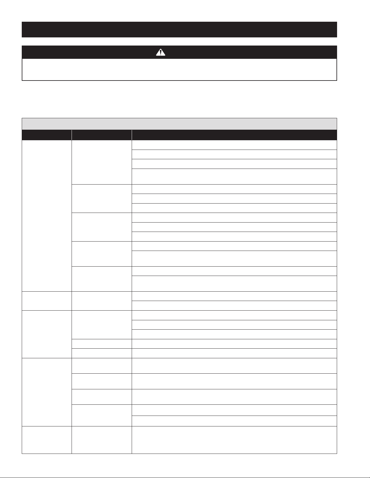
The following troubleshooting guide is intended to help diagnose and resolve general operational problems with the Steam Humidifier and
optional Fan Pack. If a problem persists, call Aprilaire Tech Support toll-free at 1-800-334-6011. Please be prepared to describe the exact nature
of the problem. For general operational problems, check to make sure humidifier is installed correctly.
TABLE 6 – Humidifier Troubleshooting Guide
Problem Possible Cause Action
General operating
problems. Humidifier
will not turn on or
turn off.
Steam Light does not
turn on.
Water is leaking from
humidifier.
Water constantly runs
down drain.
Humidifier is filling
and water is flowing
down drain but drain
light is not on.
Field-wired terminal
connections.
Internal connections. Check electrode and high water probe connections on the top of the canister.
No power to humidifier. Check main power supply and switch.
Humidifier not turned on. Make sure front cover is attached to engage safety interlock switch. Press On/Off button.
No power to 24 volt control
circuit.
Call for humidity not being
received.
Loose plumbing
connections.
Hoses are blocked. Check internal hoses and eliminate kinks or blockage.
Drain hose is blocked. Make sure drain hose has constant downward slope and is not blocked.
Debris in drain valve
preventing it from closing.
O-ring in drain valve is not
properly seated in groove.
Water is flowing from fill
cup overflow port.
High static pressure in duct
is causing back pressure in
canister.
High static pressure in
steam line is causing back
pressure in canister.
Verify L1, N/L2 and ground connections are properly wired and appropriate voltage is present.
Check HUMIDISTAT and (if used) FAN PACK terminal connections are tight and properly wired.
HUMIDISTAT terminals must be connected to an on/off device.
Check wiring connections and settings on Accessory items such as high limit switch and airflow
proving switch.
Make sure ribbon cable from membrane switch is securely plugged into control circuit board.
Make sure black/white wire is attached to terminal that matches input voltage.
Ensure breaker is sized appropriately for the amperage draw.
Check for proper voltage across L1 and N/L2 terminals.
Make sure ribbon cable from membrane switch is not damaged and is securely plugged into the
control circuit board.
Check fuse on PCB (replace with 5 amp slow burn fuse if necessary).
With humidifier energized, check that LED light D8 is energized on the circuit board. If the LED is lit,
replace the membrane switch, if not, replace the circuit board.
Check humidistat wiring and setting. (Do not leave ADHC in TEST mode.)
Check wiring and settings of high RH limit switch and airflow proving switch.
Check water supply connection at fill valve inlet. Tighten as needed.
Check internal hose clamp connections. Reposition clamps and tighten as needed.
Check steam hose connection on top of canister. Tighten clamp as needed.
Remove canister and clean debris from drain valve.
Remove canister and check O-ring for damage. Replace O-ring as necessary. Ensure O-ring is properly
seated in its groove.
Check internal hoses and eliminate kinks or blockage.
Make sure dispersion tube is not discharging into duct with greater than 2.0 in.wg static pressure.
Make sure dispersion tube tubelets are pointed up.
Install a tee and drain trap in any low points in the steam line. See Figure 9.
28
Page 29
TROUBLESHOOTING GUIDE (CONTINUED)
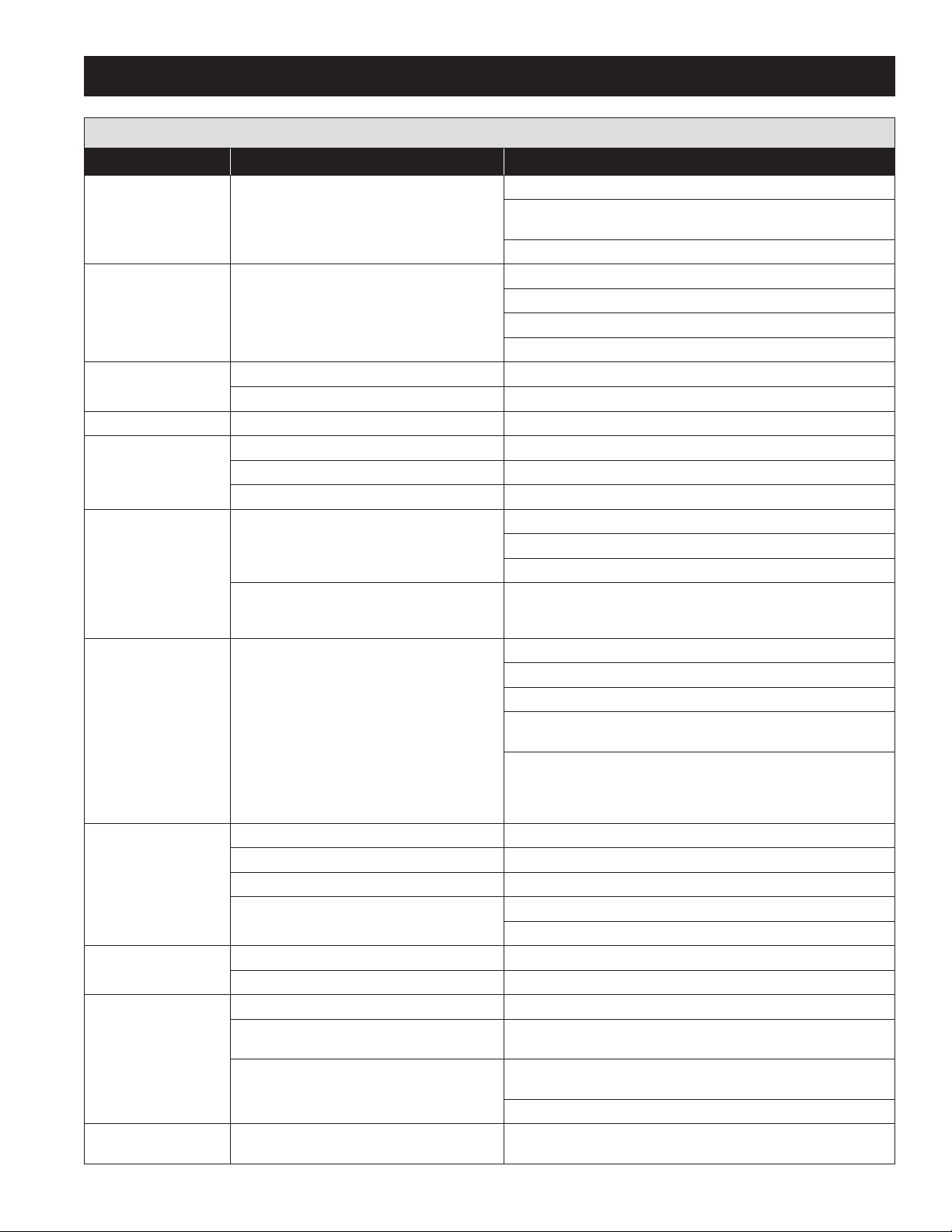
TABLE 6 – Troubleshooting Guide (continued)
Problem Possible Cause Action
Humidifier makes gurgling
sound.
Fill valve makes banging
sound.
Humidifier will not fill. Saddle valve not open or pipe not pierced. Make sure saddle valve is properly installed and the valve is open.
Humidifier will not drain. Debris in drain valve blocking outlet port. Remove canister and clean debris from drain valve.
Water in duct. Dispersion tube installed incorrectly. Install dispersion tube with tublets facing straight up.
Service light flashing
red before end of
humidification season.
Yellow steam light. Humidifier operating below rated capacity. (Normal
Humidifier is not
satisfying demand.
Excess humidity. Control setting is too high. Adjust control to lower setting.
Solid red fill light. Fill valve has been filling for 40 minutes. Make sure high water pin wire is securely installed.
Solid red service light. Unit senses current 120% above nominal and
Excess condensation in steam hose.
Water hammer from line pressure. Make sure water supply line does not contact ductwork.
Hoses are blocked. Check internal hoses and eliminate kinks or blockage.
Impurities in steam hose or pipe causing foaming. Rinse canister, fill hose and fill cup with clean water.
Insufficient absorption distance.
Canister full of mineral deposits. Remove canister and rinse with clean water.
Humidifier runs in short cycles (does not reach
capacity).
operation for systems plumbed to low conductivity
water and systems that operate for short cycles.)
Control setting is too low. Adjust control to higher setting.
Control mounted in wrong location. See Installation Instructions with control for correct mounting location.
Short run times. Use blower activation feature on ADHC or run constant HVAC fan.
Humidifier capacity limited by input power (120V). Operate humidifier on 208/240 volts.
Control mounted in wrong location. See Installation Instructions with control for correct mounting location.
Low spot in steam hose collecting water. Support steam hose along its length ensuring 2” per foot slope from the
High static pressure in the duct is causing back
pressure in the duct.
cannot lower amperage after three drain cycles.
Install Tee and Trap Model 4028 as shown in Figure 10.
Make sure steam hose has constant downward slope to humidifier or to
tees and traps in low spots of hose.
If hard pipe is used for dispersion system, make sure it is insulated.
Install shock arrestor.
Install section of 1/4" braided fill line. Conform to local codes.
If water supply pressure is greater than 120 psi, install pressure reducer.
Determine absorption distance per Table 3.
Plumb humidifier to filtered water.
Plumb humidifier to softened water.
Use blower activation feature on ADHC or run constant HVAC fan.
Allowing the humidifier to run for longer cycles to concentrate minerals
and increase water conductivity.
Plumb humidifier to softened water.
Use blower activation feature on ADHC or run constant HVAC fan.
Operate humidifier on 208/240 volts.
To determine operating current, attach clamp-on ammeter to one of the
electrode wires on top of canister.
Dissolve one teaspoon of salt into one cup of hot water. Add to the fill cup
in 1/4 cup increments until unit operates properly. Yellow steam light will
clear after first fill valve cycle at nominal amperage operation. Do not over
salt. System will drain and refill with clean water due to over current fault.
Increase capacity to 16.0 amps. Make sure breaker is appropriately sized.
dispersion tube to the humidifier.
Make sure dispersion tube is not discharging into a duct with greater than
2.0 in.wg. static pressure.
Make sure dispersion tube tubelets are pointed up.
Rinse canister to remove mineral deposits or install a new canister.
29
Page 30
TROUBLESHOOTING GUIDE (CONTINUED)
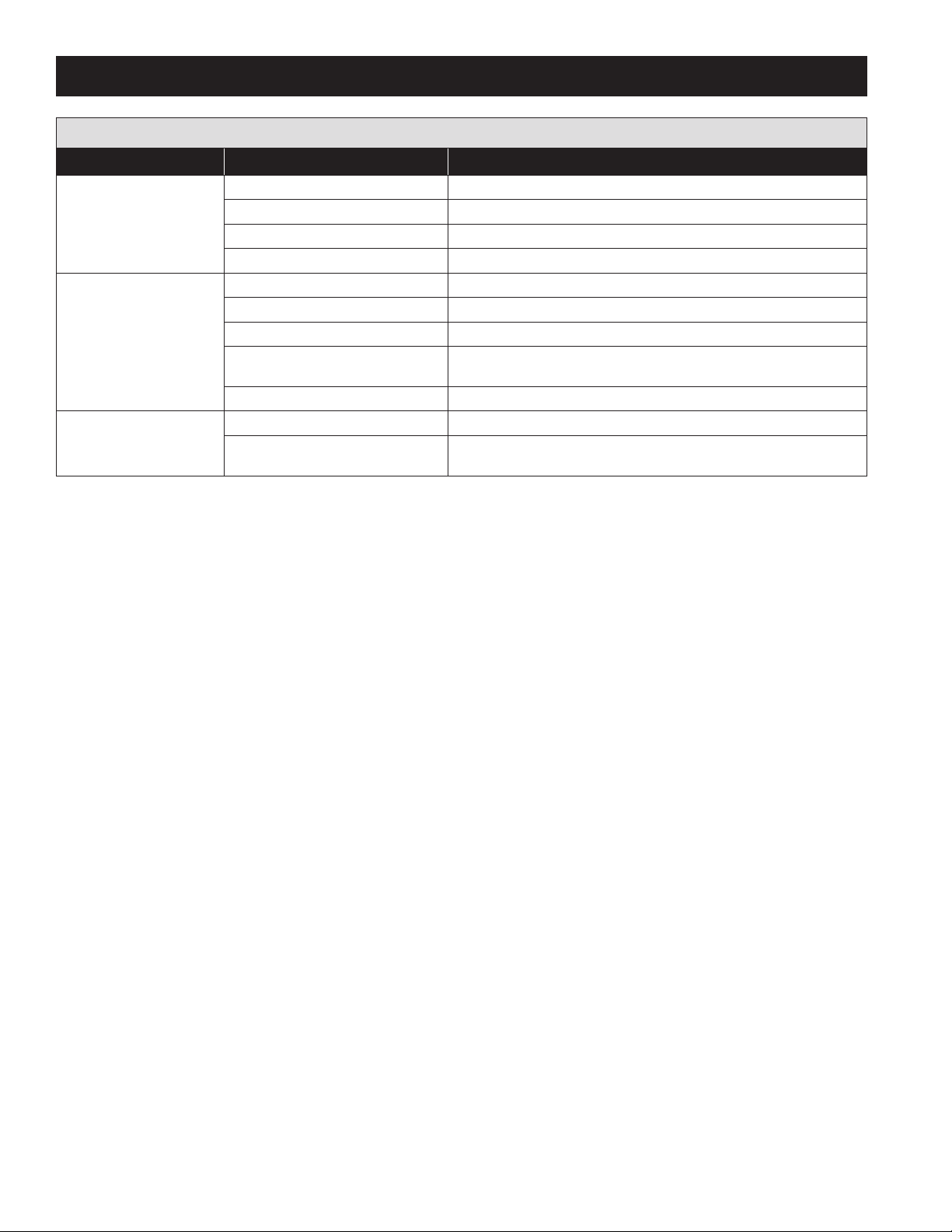
TABLE 7 – Fan Pack Troubleshooting Guide
Problem Possible cause Action
Water dripping from Fan Pack. Tubing connection. Check all connections.
Fan not operating. See “Fan does not operate”.
Steam outlets blocked. Clean steam dispersion manifold outlet.
Foaming in canister or steam hose. Rinse components with clean water.
Fan does not operate. Wiring. Check wiring.
Steam Humidifier power. Check that Steam Humidifier is powered and on.
No humidity call. Adjust humidistat setting. Check location of humidistat.
Circuit board output. Confirm 24 VAC output from Steam Humidifier FAN PACK terminals during a call
Motor failure. Replace fan motor.
Noise. Fan noise. Check for obstructions or damage to fan.
Gurgling. Add a drip tee and trap (PN 4028) to the steam line as close to the Steam
for humidity.
Humidifier as possible to divert condensation to drain. See Figure 10.
30
Page 31
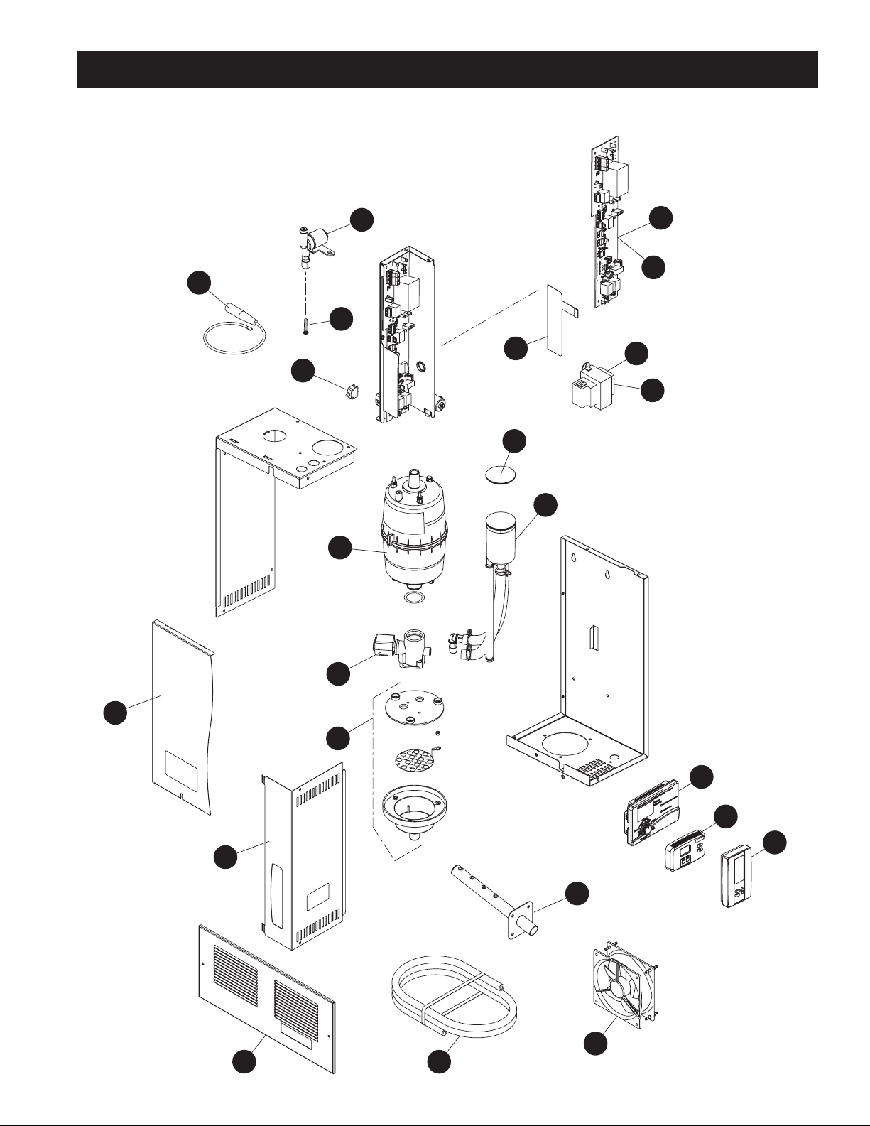
REPLACEMENT PARTS
Parts are shown for Model 800/865 humidifiers manufactured after November 2014.
For parts for steam humidifiers manufactured prior to November 2014,
refer to Aprilaire Humidifier Replacement Parts & Price List.
Refer to the following page for part descriptions.
6
17
22
4
1
2
18
10
3
12
11
14
5
8
7
15
16
23
9
13
90-1961
21
20
19
31
Page 32
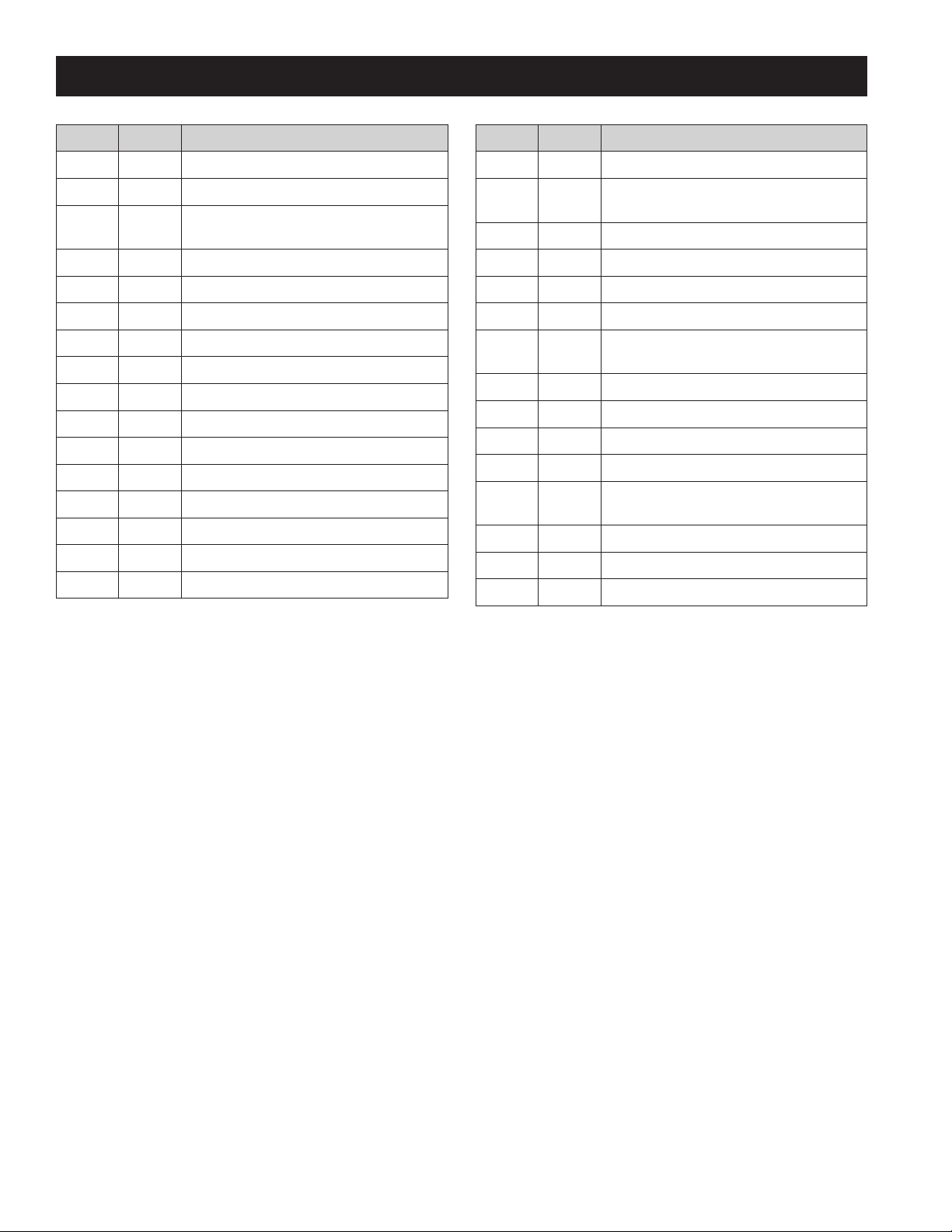
REPLACEMENT PARTS (CONTINUED)
Item No. Part No. Description
1 4004 Fill Valve In-line Strainer
2 4975 Membrane Switch
3 5306
4 4978 Electrode Wire (1)
5 4983 Drain Valve
6 5309 Fill Valve
7 4985 Drain Cup Assembly
8 4986 Front Panel & Screw
9 4987 Electrical Access Panel & Screws
10 4988 Safety Interlock Switch
11 4989 Fill Cup and Hoses
12 4990 Fill Cup Cap
13 4991 Steam Dispersion Tube & Screws
14 80 Steam Canister and O-Ring
15 62 Automatic Digital Control for Model 800
16 65 Digital Manual Humidistat
Universal Transformer, Model 865, 866
(75 VA)
Item No. Part No. Description
17 5530 Control Board, Model 800, 865
18 5529
19 4997 Condensate Tubing with Wire Ties
20 4998 Fan Pack Grille
21 4999 Fan Pack Fan
22 5554 Modulating Control Board, Model 801, 866
23 63
4001 Saddle Valve
4028 Drain Trap & Tee
4592 Airflow Proving Switch
4594 High Humidity Limit Switch
4851
4856 Condensate Pump (Rated for 160°F)
4973 Steam Hose (6 ft.) & Clamps
4974 Drain Hose (10 ft.) & Clamps
Universal Transformer, Model 800, 801
(40 VA)
Automatic Digital Modulating Control (ADMC)
for Model 801/866
Blower Activation Relay
(Optional for use with manual humidistats)
32
 Loading...