

Page 1
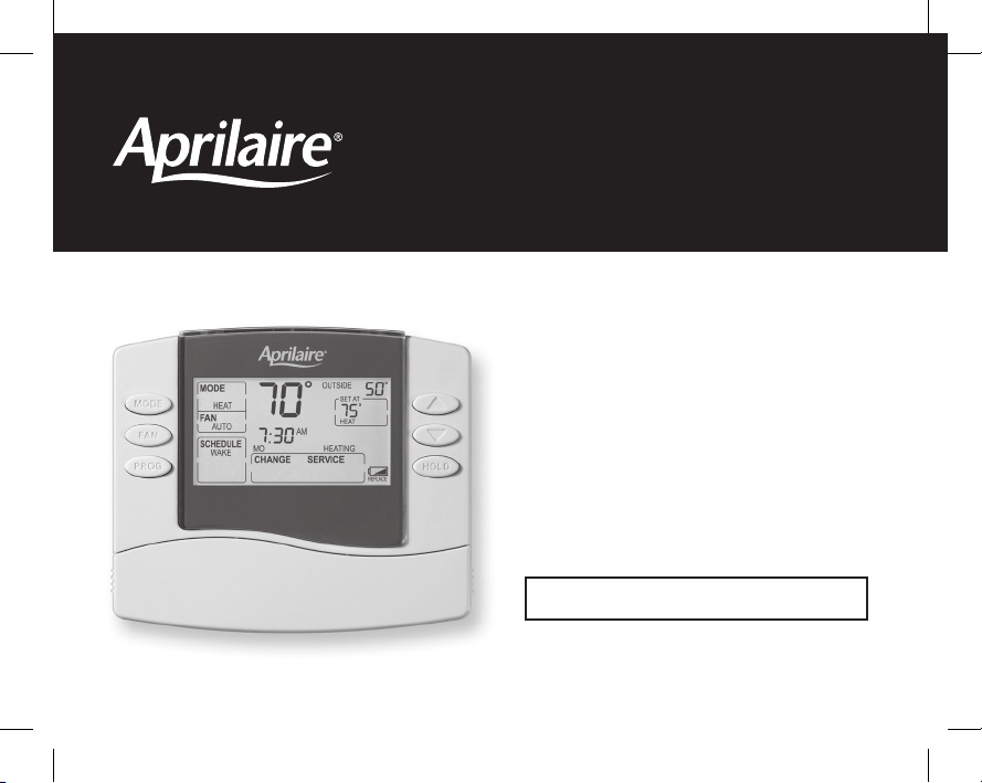
8400 Series Thermostats
Safety &
Installation
Instructions
READ AND SAVE THESE INSTRUCTIONS
61000652D 8400 Tstat Install.indd 1 7/9/13 9:03 AM
Page 2

TABLE OF CONTENTS
INSTALLATION
Installation location recommendations................................................................3
Outdoor temperature sensor (optional) ................................................................4
Thermostat mounting..............................................................................5
Power & reset options.............................................................................5
Wiring terminal ..................................................................................6
Wiring diagrams .................................................................................7
SETUP & TESTING
System setup instructions .........................................................................11
System test mode ...............................................................................16
REFERENCES
Quick reference to controls & display
•Non-programmablemodels(8444,8446,8448).....................................................22
•Programmablemodels(8463,8465,8466).........................................................23
Thermostat features .............................................................................24
Troubleshooting .................................................................................25
Specifications...................................................................................27
2
61000652D 8400 Tstat Install.indd 2 7/9/13 9:03 AM
Page 3

INSTALLATION
INSTALLATION LOCATION RECOMMENDATIONS
Thermostat should be mounted:
•Onaninteriorwall,inafrequentlyoccupiedspace.
•Approximately5‘abovefloor.
•Atleast18”fromoutsidewall.
•Thermostatcanbemountedtoaverticaljunctionbox.
Do not mount thermostat:
•Behinddoors,incorners,orotherdeadairspaces.
•Indirectsunlight,nearlightingfixtures,orother
appliancesthatgiveoffheat.
•Onanoutsideorunconditionedareawall.
•Intheflowofasupplyregister,instairwells,ornear
outside doors.
•Onawallwithconcealedpipesorductwork.
3
61000652D 8400 Tstat Install.indd 3 7/9/13 9:03 AM
Page 4
INSTALLATION
OUTDOOR TEMPERATURE SENSOR (OPTIONAL)
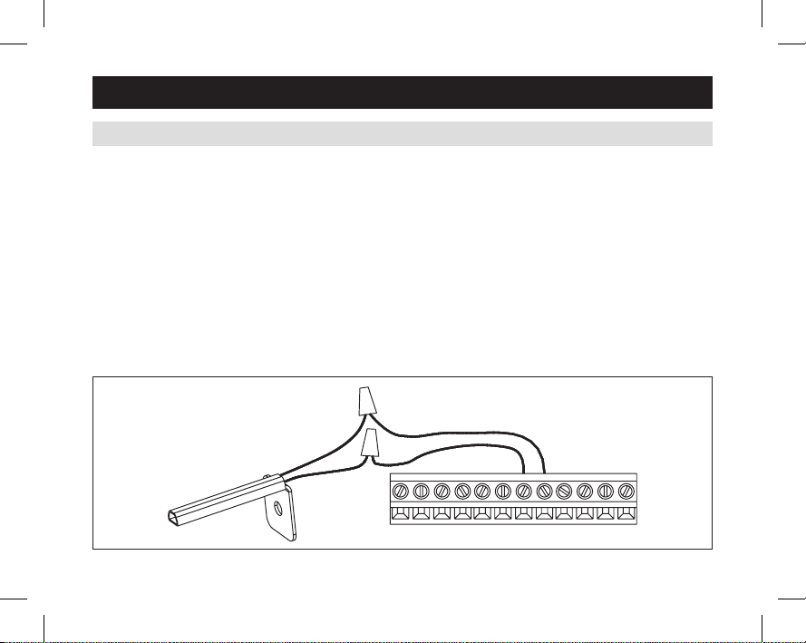
Outdoortemperaturecanbemeasuredbyattachingan
8052sensortotheS1andS2terminals.Systemsetting
#05(Remotesensor)isusedtoenablesensor.
Heat pump models can use the outdoor temperature to
effectivelyutilizetheheatpump:
•WhentheoutdoortemperatureislessthantheLow
BalancePoint,theheatpumpwillbelockedoutand
onlyauxiliaryheatingwillbeused.
•WhentheoutdoortemperatureishigherthantheHigh
BalancePoint,theauxiliaryheatingwillbelockedout
andonlytheheatpumpwillbeusedtoprovideheating.
4
•Installonsideofbuildingoutofdirectsunlight
(north side recommended).
•Mountabovesnowline.
•Mountatleast3’awayfromexhaustventsand
condensing lines.
•Maximumwirelengthis300’.
•Donotroutewiresalong120VAClines.
G
S1
C
RC
W
Y
R
S2
L
W2
O/B
Y2
61000652D 8400 Tstat Install.indd 4 7/9/13 9:03 AM
Page 5
INSTALLATION
THERMOSTAT MOUNTING
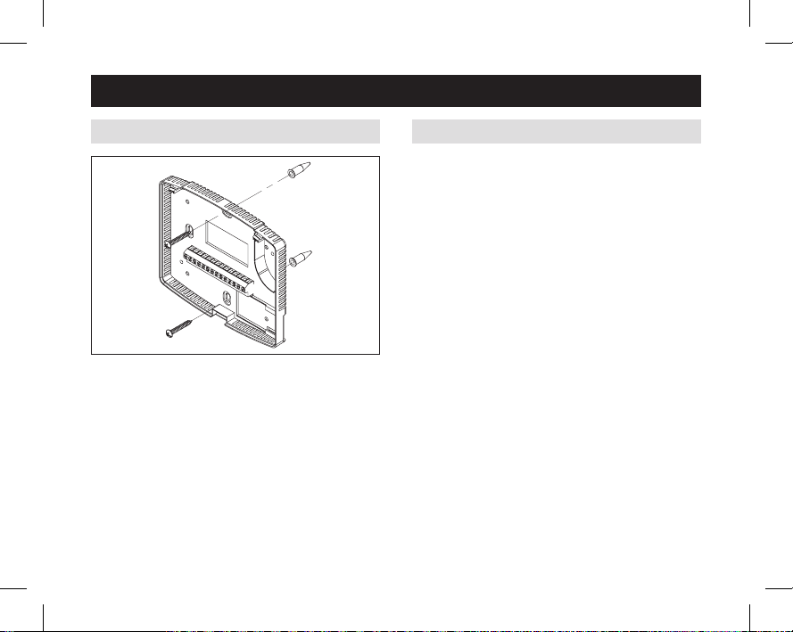
1.Removethebackofthethermostat,bypressingthe
tabonthebottomoftheunit.
2.Pullwiresthroughtheopeningonthebackofthe
thermostat.
3.Positionandlevelthebackofthethermostatonwall
and mark the hole locations with a pencil.
4.Drill1/4”holes&insertsuppliedanchors(drywallonly).
5.Placebackoveranchors,insertandtightenscrews.
6.Sealwireentryholestopreventdraftsaffecting
temperature readings.
61000652D 8400 Tstat Install.indd 5 7/9/13 9:03 AM
POWER & RESET OPTIONS
Thethermostatisdualpower.ItcaneitherbeACor
batterypowered,orboth(toprovidebackuppowerfor
theclock).Batteriesareoptionalifthethermostatwas
connectedtoACpowerwheninstalled.
Forheatpumpmodels(8446and8465)anduniversal
models(8448and8466)usedinheatpumpapplications
24VACmustbeconnectedinorderforthesystemfault
and emergency heat indicators to operate.
Thethermostathasamemorybackupthatsavesthe
thermostat’ssettingsincaseofapowerinterruption.
Theresetbuttonlocatedunderthebatterycovercanbe
usedtoresetthethermostatbacktofactorydefaults.
Thesystemsettingswillalsoberesetbacktodefaults.
5
Page 6
INSTALLATION
WIRING TERMINAL
Wire specifications
18-24gaugethermostatwire
Installation notes
•EnsurepowerattheHVACequipmentisoff.
•Loosenscrewterminals,insertstrippedwire
andre-tighten.
•Pushtheexcesswirebackintotheopening
andplugthewallopeningtopreventdrafts.
RC
R
6
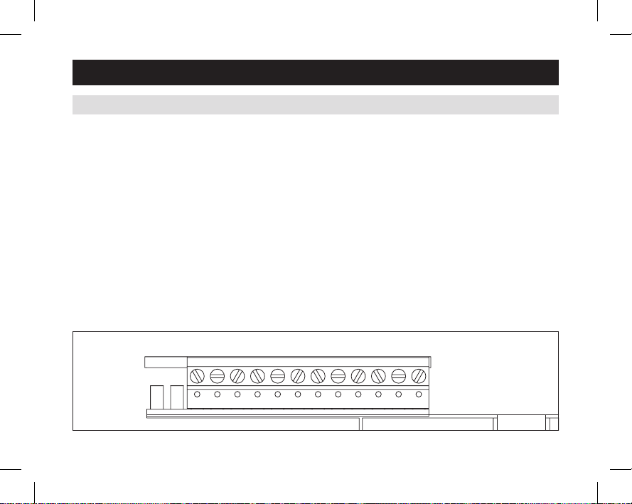
RC–24VACsupplycooling*
R–24VACsupplyheating*
W–1ststageheat/auxiliary
Y–1ststagecooling/compressor
G – Fan
C–RC24VACcommon(optionalwhenpoweredbybatteries)
S1 & S2 – outdoor temperature sensor (optional)
O/B–Reversingvalve
L – System fault indicator
W2–2ndstageheat/auxiliary
Y2–2ndstagecooling/compressor
* Jumper between RC & R is used in single transformer systems
(see wiring diagrams).
G
S1
C
W
Y
S2
O/B
Y2
L
W2
61000652D 8400 Tstat Install.indd 6 7/9/13 9:03 AM
Page 7
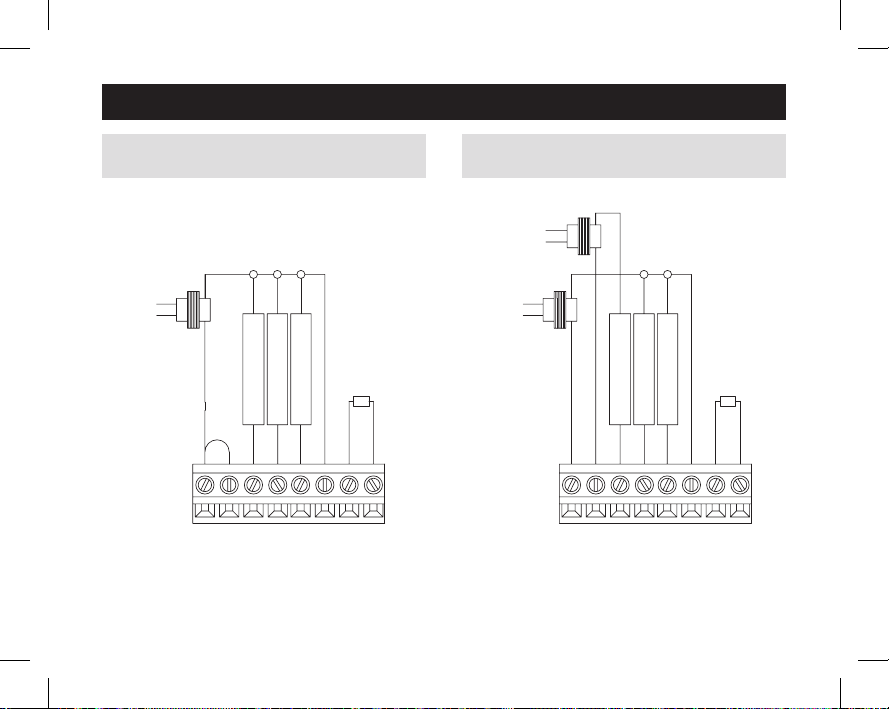
INSTALLATION
TRANSFORMER
TRANSFORMER
COOLING
WIRING – MODEL 8463 & 8444 SINGLE
TRANSFORMER (USE JUMPER WIRE)
FAN
HEATING
COOLING
RC
JUMPER
R
G
W
Y
61000652D 8400 Tstat Install.indd 7 7/9/13 9:03 AM
S1
C
SENSOR
OUTDOOR TEMP
S2
WIRING – MODEL 8463 & 8444 TWO
TRANSFORMERS (REMOVE JUMPER WIRE)
HEATING
TRANSFORMER
FAN
HEATING
COOLING
G
RC
W
R
C
Y
SENSOR
OUTDOOR TEMP
S1
S2
7
Page 8
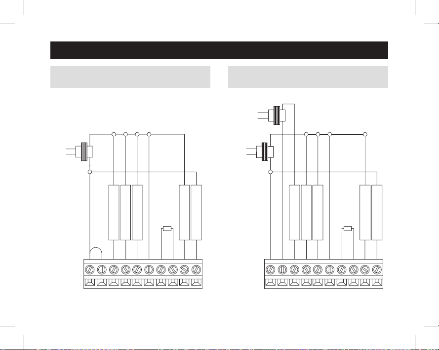
INSTALLATION
TRANSFORMER
HEAT PUMP
WIRING – MODEL 8465 & 8446 SINGLE
TRANSFORMER (USE JUMPER WIRE)
RC
JUMPER
W
R
AUX HEATING
COMPRESSOR
G
Y
FAN
S1
C
SENSOR
OUTDOOR TEMP
S2
O/B
REVERSE VALVE
FAULT DETECT
L
WIRING – MODEL 8465 & 8446 TWO
TRANSFORMERS (REMOVE JUMPER WIRE)
AUX HEATING
TRANSFORMER
TRANSFORMER
FAN
AUX HEATING
COMPRESSOR
G
S1
RC
W
R
C
Y
8
61000652D 8400 Tstat Install.indd 8 7/9/13 9:03 AM
SENSOR
OUTDOOR TEMP
REVERSE VALVE
S2
L
O/B
FAULT DETECT
Page 9
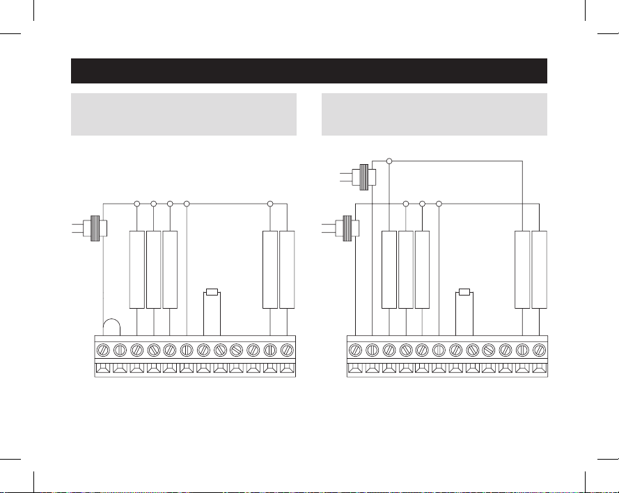
INSTALLATION
TRANSFORMER
HEATING
COOLING
WIRING – MODEL 8466 & 8448 SINGLE
TRANSFORMER (USE JUMPER WIRE)
FOR HEAT/COOL SYSTEM
FAN
1st HEATING
JUMPER
R
W
1st COOLING
G
Y
61000652D 8400 Tstat Install.indd 9 7/9/13 9:03 AM
RC
S1
C
SENSOR
OUTDOOR TEMP
NOT USED
S2
L
O/B
2nd HEATING
NOT USED
W2
Y2
WIRING – MODEL 8466 & 8448 TWO
TRANSFORMERS (REMOVE JUMPER WIRE)
FOR HEAT/COOL SYSTEM
TRANSFORMER
FAN
2nd COOLING
TRANSFORMER
RC
1st HEATING
1st COOLING
G
W
Y
R
S1
C
SENSOR
OUTDOOR TEMP
S2
O/B
NOT USED
NOT USED
L
2nd HEATING
W2
2nd COOLING
Y2
9
Page 10
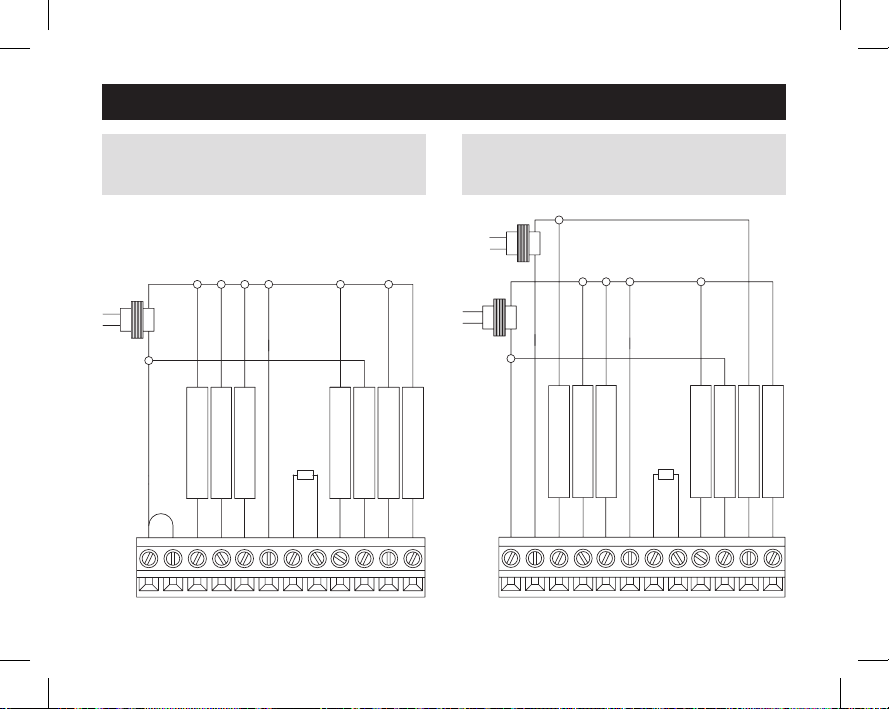
INSTALLATION
HEAT PUMP
HEATING
HEAT PUMP
WIRING – MODEL 8466 & 8448 SINGLE
TRANSFORMER (USE JUMPER WIRE)
FOR HEAT PUMP SYSTEM
TRANSFORMER
RC
JUMPER
W
R
FAN
1st AUX HEATING
1st COMPRESSOR
G
Y
S1
C
SENSOR
OUTDOOR TEMP
REVERSE VALVE
S2
O/B
FAULT DETECT
L
W2
2nd AUX HEATING
Y2
WIRING – MODEL 8466 & 8448 TWO
TRANSFORMERS (REMOVE JUMPER WIRE)
FOR HEAT PUMP SYSTEM
TRANSFORMER
TRANSFORMER
FAN
1st AUX HEATING
R
1st COMPRESSOR
W
Y
G
2nd COMPRESSOR
RC
SENSOR
OUTDOOR TEMP
S1
C
S2
O/B
10
61000652D 8400 Tstat Install.indd 10 7/9/13 9:03 AM
REVERSE VALVE
FAULT DETECT
L
W2
2nd AUX HEATING
2nd COMPRESSOR
Y2
Page 11
SETUP & TESTING
SYSTEM SETUP INSTRUCTIONS
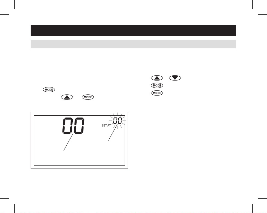
Thefollowinginstructionsshowhowtoenterthesystemsetupmenuandchangesettings.Thetableonthe
followingpagesliststhesettingsandtheirdetails.Defaultsettingsareshowninbold. Some settings are only
availabletocertainmodels,andsomearespecifictothermostatssettoheatpumpmode.
How to enter the system setup menu to change
system settings
Press
Press and hold
repeatedly until system is set to OFF.
and for three seconds.
Thescreenofthefirstsettingwillbedisplayed.
Press or to change the setting.
Press
Press
tochangetothenextoption.
afterthelastsetting.“DONE”willbe
displayed.
ThethermostatwillsavechangesandreturntoNormal
modeifnokeyispressedfor20seconds.
Toresetallsystemsettingsbacktodefault,pressthe
RESETbuttonlocatedunderthebatterydoor.
SETTINGVALUE
SYSTEMSETTINGNUMBER
11
61000652D 8400 Tstat Install.indd 11 7/9/13 9:03 AM
Page 12
SETUP & TESTING
SYSTEM SETUP INSTRUCTIONS (CONTINUED)
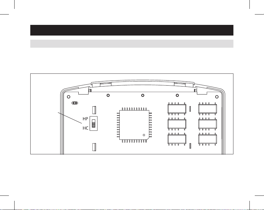
Thermostatmodels8448&8466havetheoptionofbeingusedinheatpumporheat/coolsystems.Theequipment
typeswitchlocatedonthebackofthethermostat’sfaceisusedtoselectthis.Systemsettingnumber00willonlybe
shownonthesemodelstodisplaythepositionoftheequipmenttypeswitch.
EQUIPMENT
TYPE SWITCH
HEATPUMP
HEAT/COOL
12
61000652D 8400 Tstat Install.indd 12 7/9/13 9:03 AM
Page 13
SETUP & TESTING
SYSTEM SETUP INSTRUCTIONS (CONTINUED)
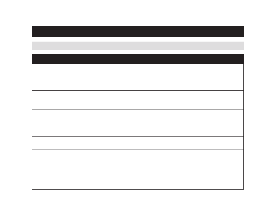
System setting Setting range, default in bold
00Equipmenttype(8466,8448)
(Set by the equipment type switch)
01 Temperature scale
02Heat/Cool:Fancontrolinheating
HeatPump:Auxiliaryequipmenttype
03 Offset temperature for internal sensor
04Autochangeovermode
05 Outdoor temperature sensor
06Compressorminimumofftime
07 Heating minimum off time
08Equipmentminimumontime
0:heat/cool
1:heatpump
0 : Fahrenheit
1:Celsius
0 : Gas or oil furnace (Equipment controls fan)
Note:UsedforDualFuelapplications
1:Electric(Thermostatcontrolsfan)
0° : No offset applied
–4°Fto+4°F(–2°Cto+2°C)
0 : Auto changeover mode is disabled
1:Autochangeovermodeisenabled
0 : No outdoor temperature sensor attached
1:Outdoortemperaturesensorattached
5 minutes
1 to 5 minutes in 1 minute steps
2 minutes
1 to 5 minutes in 1 minute steps
2 minutes
1 to 5 minutes in 1 minute steps
13
61000652D 8400 Tstat Install.indd 13 7/9/13 9:03 AM
Page 14
SETUP & TESTING
SYSTEM SETUP INSTRUCTIONS (CONTINUED)
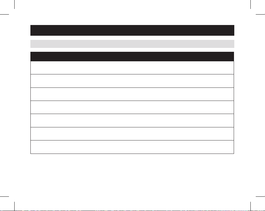
System setting Setting range, default in bold
09 1st stage differential
102ndstagedifferential(8448,8466)
113rdand4thstagedifferential(8448HP,8466HP)
12Reversevalve(8446,8448HP,8465,8466HP)
13Stagerate*
14Deadband(automode)
15Progressiverecovery(8463,8465,8466)
*Accumulationofequipmentruntimeinequipmentstagingdetermination.
1=morerapidstagingofequipment(comfort).
5=slowerstagingofequipment(economy).
14
1°F (0.5°C)
1°Fto4°F(0.5°Cto2°C)
1°F (0.5°C)
1°Fto4°F(0.5°Cto2°C)
1°F (0.5°C)
1°Fto4°F(0.5°Cto2°C)
0 – O/B energized in cooling (O)
1–O/Benergizedinheating(B)
4
1to5or“OFF”todisable
3°F (2°C)
2°Fto5°F(1°Cto3°C)
0:Progressiverecoveryisdisabled
1 : Progressive recovery is enabled
61000652D 8400 Tstat Install.indd 14 7/9/13 9:03 AM
Page 15
SETUP & TESTING
SYSTEM SETUP INSTRUCTIONS (CONTINUED)
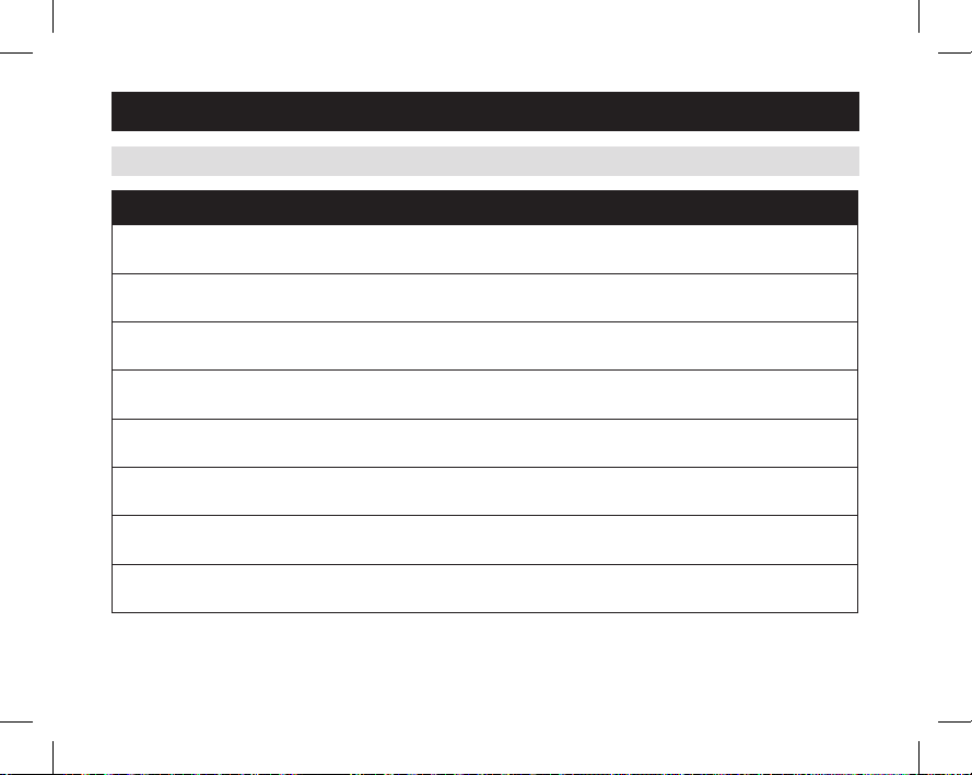
System setting Setting range, default in bold
16LowBalancePt.(8446,8448HP,8465,8466HP)
Systemsetting05mustbeenabled
17HighBalancePt.(8446,8448HP,8465,8466HP)
Systemsetting05mustbeenabled
19Programformat(8463,8465,8466)
20Changeairfilter
21Changewaterpanel**
Setnumberofmonthsuntilreminderisrequired
22Humidifiertype**
23Servicedehumidifier
24ServiceHVAC
**IfhumidifiertypeissettoDrain-less,thenthefirstreminderisbasedonthesystemsetting21,secondreminder
willactivate3monthslater.IfhumidifiertypeissettoFlowthrough,thenthefirstreminderisbasedonsystem
setting21,secondreminderwillactivate12monthslater.
20°F (–7°C)
1°Fto35°F(–17°Cto1°C)or“OFF”todisable
60°F (16°C)
40°Fto80°F(4°Cto27°C)or“OFF“todisable
0 – 5/2 program (Weekdays and Weekends)
1–5/1/1program(Weekdays,Sat.andSun.)
OFF
1,3,6,12monthsor“OFF”todisable
OFF
1to12monthsor“OFF”todisable
0 : Flow through type humidifier (1 reminder per season)
1:Drain-lesstypehumidifier(2 reminders per season)
OFF
1to12monthsor“OFF”todisable
OFF
1to12monthsor“OFF”todisable
15
61000652D 8400 Tstat Install.indd 15 7/9/13 9:03 AM
Page 16
SETUP & TESTING
SYSTEM TEST MODE
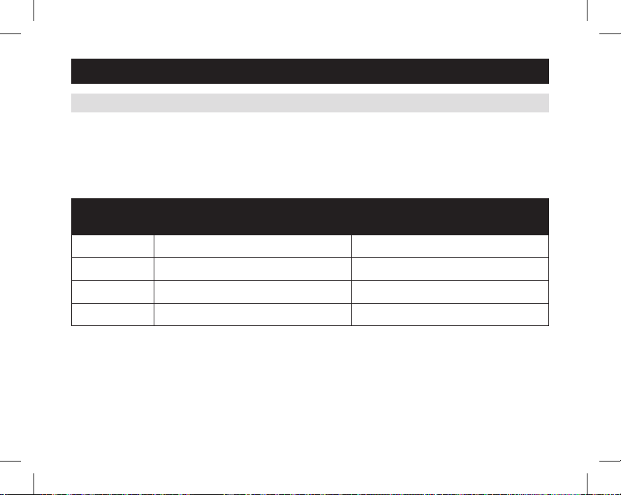
Thesystemtestmodeisusedtotestasystemafterinstallation.Theoutputsofthethermostatcanbemanually
activatedoneatatimetotesttheirfunction.Thefollowinginstructionsshowhowtoenterthetestmodeandturn
outputs on and off. The charts on the following pages show all of the options for each model.
The test steps are:
Test
Number
50 Heating (W) (W2) AuxHeating(W)(W2)
51 Cooling(Y)(Y2) CompressorCooling(Y)(Y2)
52 Fan(G) CompressorHeating(Y)(Y2)
53 Fan(G)
16
61000652D 8400 Tstat Install.indd 16 7/9/13 9:03 AM
Heat/Cool Models
8444, 8463, 8448HC, 8466HC
Heat Pump Models
8446, 8465, 8448HP, 8466HP
Page 17
SETUP & TESTING
SYSTEM TEST MODE (CONTINUED)
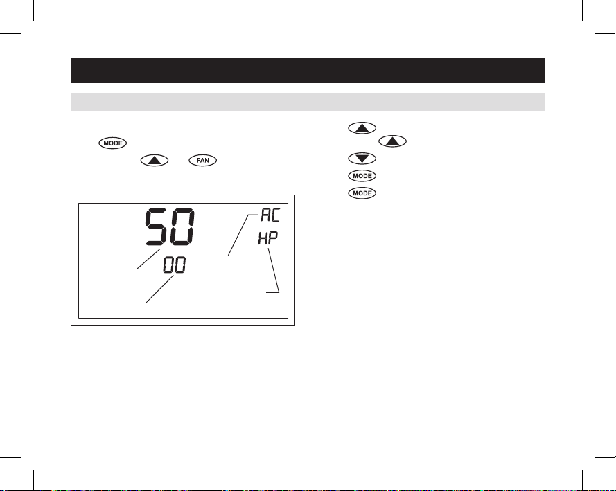
How to enter the system test menu
Press
Press and hold
Thescreenofthefirstteststep#50isdisplayed:
repeatedly until system is set to OFF.
and for three seconds.
Press toturnontheoutput(01).Formultistage
output,press
Press
Press
Press
againtoturnonthe2ndstage(02).
toturnofftheoutput(00).
tochangetothenextteststep.
afterthelastteststep.“DONE”willbe
displayed.
ThethermostatwillreturntoNormalmodeifnokeyis
pressedin20seconds.
SYSTEMTEST
NUMBER
OUTPUTSTATUS
61000652D 8400 Tstat Install.indd 17 7/9/13 9:03 AM
FLASHESIF24VAC
ISNOTPRESENT
MODE(SW1SETTING
8448&8466ONLY)
17
Page 18

SETUP & TESTING
Step Key Input
#50Heat
#51Cool
#52 Fan
18
Test steps for 8444 & 8463
System Setting Display (Output)
#2
0:Gas ON
[UP]
1:Elec ON ON
[DOWN]
[UP] ON ON
[DOWN]
[UP] ON
[DOWN]
01
HEATING
ON (W)
01
COOLING
ON (Y)
01
FAN ON
(G)
61000652D 8400 Tstat Install.indd 18 7/9/13 9:03 AM
Page 19
SETUP & TESTING
Step Key Input
1st[UP]
#50Heat
#51Cool
#52 Fan
2nd[UP]
[DOWN]
1st[UP]
2nd[UP] ON ON ON
[DOWN]
[UP] ON
[DOWN]
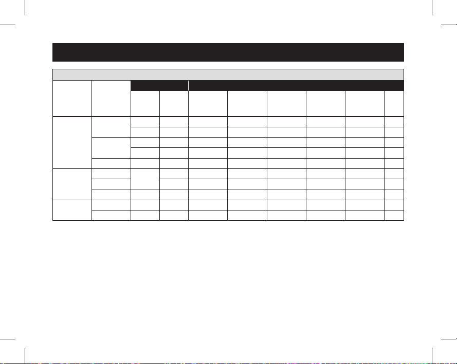
Test steps for 8448HC & 8466HC
System Setting Display (Output)
#2
0:Gas ON
1:Elec ON ON
0:Gas ON ON
1:Elec ON ON ON
ON ON
01
HEATING
ON (W)
02
HEATING
ON (W2)
01
COOLING
ON (Y)
02
COOLING
ON (Y2)
01
FAN ON
(G)
19
61000652D 8400 Tstat Install.indd 19 7/9/13 9:03 AM
Page 20
SETUP & TESTING
Step Key Input
#50Aux
#51Cool
#52 Heat
#53 Fan
20
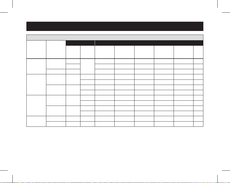
Test steps for 8446 & 8465
System Setting Display (Output)
#2 #12
0:Gas
[UP]
1:Elec ON ON
[DOWN]
[UP]
[DOWN]
[UP]
[DOWN]
[UP] ON
[DOWN]
01 AUX
HEATING
ON (W)
ON
0:O ON ON ON
1:B ON ON
0:O ON
1:B
0:O ON ON
1:B ON ON ON
0:O
1:B ON
01
COOL/HEAT
ON (Y)
01
FAN ON
(G)
O/B
61000652D 8400 Tstat Install.indd 20 7/9/13 9:03 AM
Page 21
SETUP & TESTING
Step Key Input
1st[UP]
#50Aux
#51Cool
#52 Heat
#53 Fan
2nd[UP]
[DOWN]
1st[UP]
2nd[UP]
[DOWN]
1st[UP]
2nd[UP]
[DOWN]
[UP] ON
[DOWN]
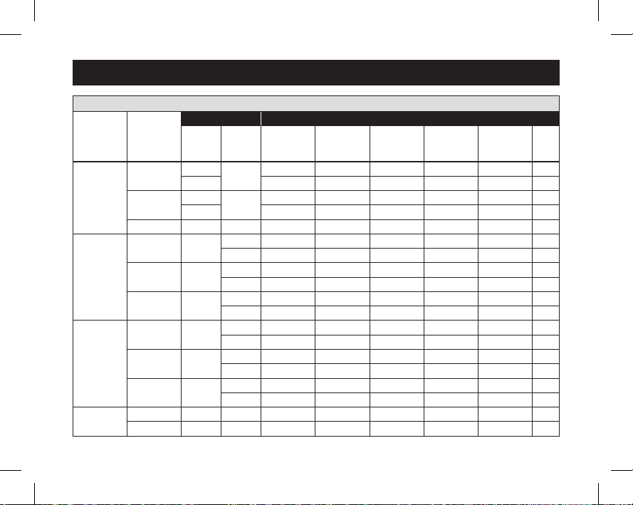
Test steps for 8448HP & 8466HP
System Setting Display (Output)
#2 #12
0:Gas
1:Elec ON ON
0:Gas
1:Elec ON ON ON
01 AUX
HEATING
ON (W)
0:O ON ON ON
1:B ON ON
0:O ON ON ON ON
1:B ON ON ON
0:O ON
1:B
0:O ON ON
1:B ON ON ON
0:O ON ON ON
1:B ON ON ON ON
0:O
1:B ON
ON
ON ON
02 AUX
HEATING
ON (W2)
01
COOL/HEAT
ON (Y)
02
COOL/HEAT
ON (Y2)
01
FAN ON
(G)
O/B
21
61000652D 8400 Tstat Install.indd 21 7/9/13 9:03 AM
Page 22
QUICK REFERENCE TO CONTROLS & DISPLAY
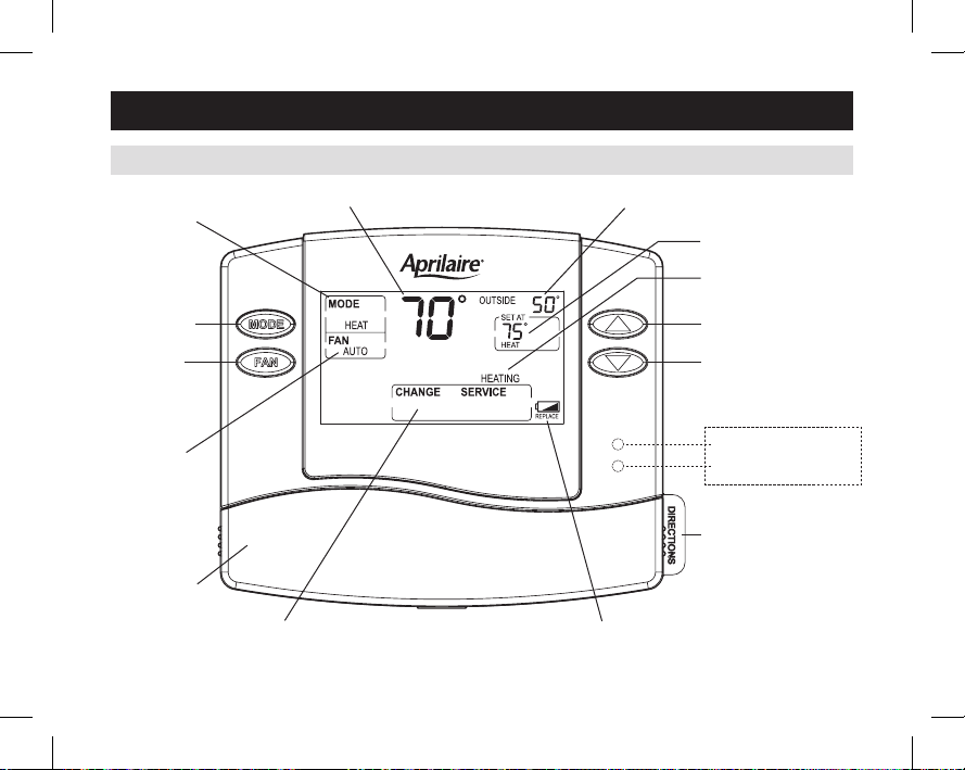
NON-PROGRAMMABLE MODELS (8444, 8446, 8448)
CURRENTINDOORTEMPERATURE
SYSTEMMODE
SETTING
OUTDOORTEMPERATURE(OPTIONAL)
TEMPERATURESETTING
EQUIPMENTSTATUS
SYSTEMMODE
FANSETTING
FANSETTING
BATTERYDOOR
MESSAGECENTER LOWBATTERYWARNING
22
61000652D 8400 Tstat Install.indd 22 7/9/13 9:03 AM
NOTE:BACKLIGHTISACTIVATEDWITHFIRSTBUTTONPRESSANDAUTOMATICALLYTURNSOFF.
UP
DOWN
HEAT PUMP MODELS ONLY
EMERGENCYHEAT(RED)
SYSTEMFAULT(YELLOW)
INDICATORSHOWSTHROUGHHOUSING
QUICKREFERENCECARD
Page 23
QUICK REFERENCE TO CONTROLS & DISPLAY
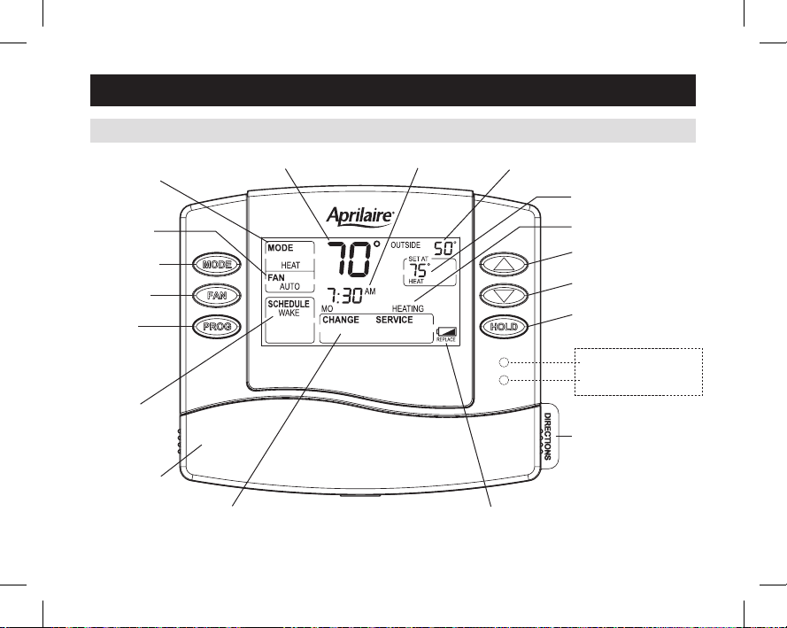
PROGRAMMABLE MODELS (8463, 8465, 8466)
SYSTEMMODE
SETTING
FANSETTING
SYSTEMMODE
FANSETTING
PROGRAM
CURRENT
SCHEDULE
PERIOD
BATTERYDOOR
CURRENTINDOORTEMPERATURE
MESSAGECENTER LOWBATTERYWARNING
CURRENTTIME
OUTDOORTEMPERATURE(OPTIONAL)
TEMPERATURESETTING
EQUIPMENTSTATUS
UP
DOWN
HOLD
HEAT PUMP MODELS ONLY
EMERGENCYHEAT(RED)
SYSTEMFAULT(YELLOW)
INDICATORSHOWSTHROUGHHOUSING
QUICKREFERENCECARD
NOTE:BACKLIGHTISACTIVATEDWITHFIRSTBUTTONPRESSANDAUTOMATICALLYTURNSOFF.
61000652D 8400 Tstat Install.indd 23 7/9/13 9:03 AM
23
Page 24

THERMOSTAT FEATURES
ALL 8400 SERIES THERMOSTATS
•Large,clear,backlitdisplayiseasytoread–even
in the dark.
•Displaysroomtemperature,temperaturesetting,and
optional outdoor temperature.
•Dualpoweroption(Batteryor24VAC).
•Frontbatterydooraccessforfast,easyreplacement.
•Builtincompressorprotection.
•Circulationfanmodeforaircleaning.
•Waterpanel,dehumidifier,airfilter,andHVAC
serviceindicators.
•Systemtestmode.
24
61000652D 8400 Tstat Install.indd 24 7/9/13 9:03 AM
PROGRAMMABLE MODELS ONLY
(8463, 8465, 8466)
•Separatelyprogrammableweekday/weekend
schedules.
•Easytousetemperaturecontrolcanoverride
program schedule at any time.
•Progressiverecovery.ProgressiveRecoveryfeature
allowsthethermostattoactivatetheheatingand
coolingequipmentpriortoaneventinordertoreach
thedesiredtemperatureatthestartofthenext
scheduledevent.
Page 25

TROUBLESHOOTING
DISPLAY IS BLANK
•Checkcircuitbreakerandresetifnecessary.
•Makesurepowerswitchatheating&cooling
system is on.
•Makesurefurnacedoorisclosedsecurely.
•Ifthermostatisbatterypowered,makesurefreshAA
alkalinebatteriesarecorrectlyinstalled.
TEMPERATURE SETTINGS DO NOT CHANGE
Makesureheatingandcoolingtemperaturesaresetto
acceptableranges:
• Heat:45°to90°F(7°to32°C).
• Cool:50°to99°F(10°to37°C).
61000652D 8400 Tstat Install.indd 25 7/9/13 9:03 AM
HEATING SYSTEM DOES NOT RESPOND
(“HEATING” APPEARS ON SCREEN)
•Checkfor24VACattheequipmentonthesecondary
sideofthetransformerbetweenpowerand
common.Ifvoltageisnotpresent,checktheheating
equipmenttofindthecauseoftheproblem.
•Checkfor24VACbetweentheheatterminal(W)
andthetransformercommon.If24VACispresent,
thethermostatisfunctional.Checktheheating
equipmenttofindthecauseoftheproblem.
•Checkforlooseorbrokenwiresbetweenthe
thermostatandtheheatingequipment.
25
Page 26

TROUBLESHOOTING
COOLING SYSTEM DOES NOT RESPOND
(“COOLING” APPEARS ON SCREEN)
•Checkfor24VACattheequipmentonthesecondary
sideofthetransformerbetweenpowerand
common.Ifvoltageisnotpresent,checkthecooling
equipmenttofindthecauseoftheproblem.
•Checkfor24VACbetweenthecoolingterminal(Y)
andthetransformercommon.If24VACispresent,
thethermostatisfunctional.Checkthecooling
systemtofindthecauseoftheproblem.
•Checkforlooseorbrokenwiresbetweenthe
thermostatandthecoolingequipment.
FAN DOES NOT TURN ON IN A CALL FOR HEAT
•CheckSystemSetting#02(FanControl),tomake
sure the fan control is properly set to match the type
of system (see page 11).
HEAT PUMP ISSUES COOL AIR IN HEAT MODE,
OR WARM AIR IN COOL MODE
•CheckSystemSetting#12(ReversingValve),tomake
sure it is properly configured for your system (see
page 11).
26
61000652D 8400 Tstat Install.indd 26 7/9/13 9:03 AM
HEAT/COOL BOTH ON AT SAME TIME
•CheckSW1(EquipmentType),tomakesureitisset
tomatchtheinstalledheating/coolingequipment
(see page 12).
•Checktomakesureheatingandcoolingwiresare
not shorted together.
HEATING EQUIPMENT IS RUNNING IN
COOL MODE
•CheckSW1(EquipmentType),tomakesureitisset
tomatchtheinstalledheating/coolingequipment
(see page 12).
“HEATING” IS NOT DISPLAYED
•ChangetheSystemModetoHeat,andset
thetemperaturelevelabovethecurrentroom
temperature.
“COOLING” IS NOT DISPLAYED
•ChangetheSystemModetoCool,andset
thetemperaturelevelbelowthecurrentroom
temperature.
Page 27
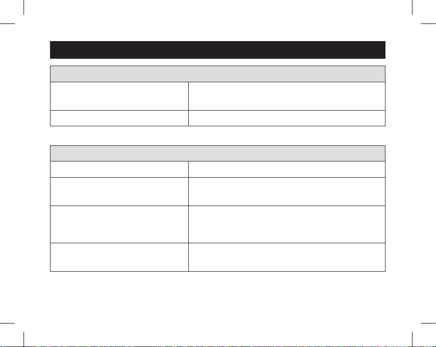
SPECIFICATIONS
Environment
Temperature
Relativehumidity Operating:5%to90%R.H.(non-condensing)
Operatingvoltage 24VAC(18–30VAC)
Current
Power supply
Batterypower
Operating:32°to120°F(0°to48.9°C)
Shipping:-30°to140°F(-34.4°to60°C)
Electrical
Maximum:2.5A(total),1.0A(singleoutput)
Maximumsurgecurrent:5A
Dualpower.Canbebatteryor24VACpowered.
Whenboththesourcesareavailable,batterywillbeusedas
backuppower.
Batterypower:AAsizealkalinebatteryx2
Batterylife:Approximately1year
27
61000652D 8400 Tstat Install.indd 27 7/9/13 9:03 AM
Page 28
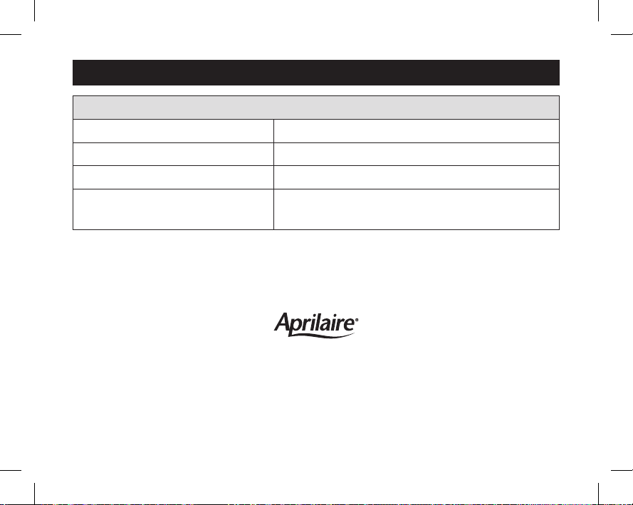
SPECIFICATIONS
Thermal
Outdoor temperature sensor Maximumdistance:300feet
Roomtemperaturemeasurement Displayrange:32°to99°F(0°to40°C)
Outdoor temperature measurement Displayrange:-20°to130°F(-30°to55°C)
Temperature setting range
P.O.Box1467•Madison,WI53701-1467•Phone:800/334-6011 •Fax:608/257-4357
610006527.13
B2204777D ©2013Aprilaire–AdivisionofResearchProductsCorporation
28
Heat:45°to90°F(7°to32°C)
Cool:50°to99°F(10°to37°C)
www.aprilairepartners.com
61000652D 8400 Tstat Install.indd 28 7/9/13 9:03 AM
 Loading...