

Page 1
SAFETY AND INSTALLATION MANUAL
ENERGY RECOVERY VENTILATORS
®
MODEL 8100
• Provides year-round fresh air
• Recovers 77% of the apparent heating or cooling energy from the exhausted air
See Warnings – Page 3
Page 2

Table of Contents
Safety Instructions ……………………………………………………3
®
Aprilaire
Specifications …………………………………………………………5
Components …………………………………………………………6
Operation ……………………………………………………………7
Procedure and Equipment Required …………………………………7
New Home Installation
A. Location ………………………………………………………8
B. General Mounting Information ………………………………8
C. Mounting the Unit …………………………………………8-12
Energy Recovery Ventilator System Diagram ………………4
D. Ductwork Specifications ……………………………………12
E. Grille and Hood Specifications ………………………………12
F. Ductwork Connection – Forced Air System …………………12
G. Electrical Connection ………………………………………13
Installation into Existing Home (Retrofitting) …………………………14
Installation into Homes Without Forced Air System …………………14
System Start Up ……………………………………………………14
Balancing the System ………………………………………………15
Balancing Diagram …………………………………………………16
© Research Products Corporation 2001
Page 3

SAFETY INSTRUCTIONS
Read the Safety and Installation Instructions carefully. They will help insure a correct and
®
SAFE installation of the Aprilaire
Energy Recovery Ventilator.
WARNINGS:
1. 120 Volts may cause serious injury from electrical shock. Sudden operation may cause serious injury
from moving parts. Leave power disconnected until installation is completed.
2. The fresh air intake
Examples of such sources, but not limited to these sources, include the exhausts from condensing
furnaces, condensing water heaters and vented space heaters. These exhausts contain toxic
substances that can be harmful to humans.
The fresh air
3. Connection with existing air exhaust sources may cause toxic conditions in the living area. The
Aprilaire ducting must be separate from sources such as dryer vents, water heater, furnace flues,
gas appliance flues or bathroom and kitchen exhausts.
4. Unit weight and dropping may cause personal injury or equipment damage. Handle with care and
follow installation instructions.
5. WARNING: To avoid serious injury, do not mount unit with access door facing down.
Unit must be mounted in an upright position.
6. Sharp edges may cause serious injury from cuts. Wear protective gloves and handle with care.
7. Excess negative or positive pressure may cause health problems or structural damage. Air flow
must
be balanced after installation.
must be
intake
should be installed a minimum of 10 feet from any exhaust vent.
mounted in a location removed from sources of dangerous toxic gases.
8. Insufficient combustion air may cause toxic conditions. The Energy Recovery Ventilator
exhaust air from an enclosed room with combustion appliances.
9. Installation
10. The fresh air duct from outside the Energy Recovery Ventilator and the stale air duct from the
Energy Recovery Ventilator to the outside
to the unit
the ductwork.
NOTE: This manual does not express or imply any warranty conditions. See Owner’s Manual for further information.
must
conform to all applicable codes.
must
be fully insulated. The fresh air duct connection
must
also be completely insulated. This is to prevent condensation from forming on
–3–
must not
Page 4
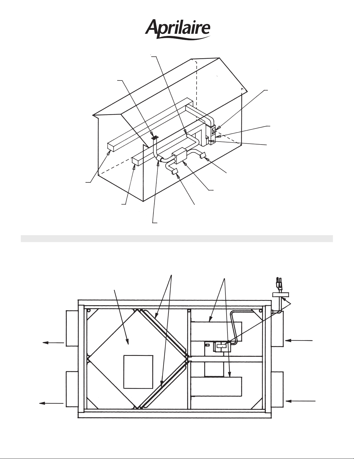
FRESH AIR TO HOUSE
STALE AIR FROM HOUSE
(Centrally Located such as
Hallway or Foyer)
SUPPLY AIR
®
THE BEST IN INDOOR AIR COMFORT
APRILAIRE® ENERGY
RECOVERY VENTILATOR
APRILAIRE
AUTOMATIC HUMIDIFIER
FURNACE
APRILAIRE® HIGH
EFFICIENCY AIR CLEANER
STALE AIR TO OUTSIDE
®
FIGURE 1
FRESH
AIR TO
HOUSE
(DAMPERED
DUCT)
STALE AIR
TO OUTSIDE
(INSULATED
DUCT)
RETURN AIR
ENERGYMAX
®
TRANSFER CORE
FRESH AIR FROM OUTSIDE
AIR MOVEMENT SOUND ABSORBER
E Z KLEEN
WASHABLE ALUMINUM
AIR FILTERS
INSTR.
LABEL
®
POWER
BLOWER
ASSEMBLY
CORD 120
VAC
WARNING
LABELS
STALE AIR
FROM
HOUSE
(DAMPERED
DUCT)
FRESH AIR
FROM
OUTSIDE
FIGURE 1A
(INSULATED
DUCT)
–4–
Page 5

SPECIFICATIONS
Model: The Aprilaire®Model 8100 Energy Recovery Ventilator is
an enthalpy (sensible and moisture transfer) type unit.
®
The unique paper/aluminum EnergyMax
exchanges energy between the fresh air supply and
exhaust air streams.
3
Unit Dimensions: Overall Unit – 37
EnergyMax
⁄8" W x 123⁄4" D x 209⁄16" H
®
Transfer Core – 121⁄8" x 121⁄8" x 103⁄4".
Air Flow Capacity: 120 cfm @ 0.30 in. w.g. external ductwork resistance, i.e.
240 equivalent feet for each of the “fresh” and “stale”
air streams.
Performance: Apparent Sensible Effectiveness (ASE) – 77% at rated
ventilation capacity with 72ºF indoor temperature and
32ºF outdoor temperature.
Transfer Core
Home Size: Up to 3600 sq. ft. home at rated air flow.
Power Requirements: 120 VAC, 1.4 ampere maximum. Unit equipped with a
3 ft. grounded power cord.
Interior Insulation: Entire interior surface is sealed with 1" single face insulation.
Filters: (2) – 10
13
⁄16" x 115⁄16" x 3⁄32" EZ Kleen®air filters coated with
Super Filter Coat adhesive for maximum performance.
Unit Weight and
Packaging: Total Shipping Weight with Mounting Hardware – 76 lbs.
–5–
Page 6

Energy Recovery Ventilator Components
MACHINE
SCREWS
OWNERS
MANUAL
HANGING HOOK
BRACKET
UNIT
HANGING PINS &
THREADED NUTS
ACCESS DOOR
MOUNTING BRACKET
WARRANTY
CARD
FIGURE 2
LAG BOLTS &
WASHERS
HANGING HINGE
BRACKET
–6– –11–
Page 7

GENERAL INFORMATION
OPERATION
The Aprilaire®Energy Recovery Ventilator is designed to
work in conjunction with the home’s forced air system, or
totally independent, incorporating its own duct system to
provide the homeowner with 1) a supply of fresh air
distributed into the living space and 2) to exhaust stale air
from the home to the outdoors through the EnergyMax
Transfer Core. It is designed to handle homes with up to
3,600 ft
2
living space.
During the winter season, the cross flow design of the
®
EnergyMax
Transfer Core allows the incoming cold fresh
outside air to be preheated by the warm stale air being
exhausted, reducing the energy required to heat the
incoming fresh air.
During the air conditioning season the Aprilaire Energy
Recovery Ventilator operates with a reverse effect. Cool
stale air, exhausted from the house, cools the incoming
warm fresh air. It also removes moisture from the incoming
fresh air to the home.
PROCEDURE AND EQUIPMENT REQUIRED
Read the installation instructions carefully to become
familiar with the requirements and refer to the proper
section of the instructions if any installation question
arises.
The Aprilaire Energy Recovery Ventilator is preassembled
and ready to install. See Figure 2 to become familiar with
all components and inspect unit and box containing all
mounting hardware to be sure all components are
included.
The following equipment will be needed and is detailed
throughout the manual.
Mounting – A mounting system is provided with the unit,
which requires 1/4" x 3" lag bolts (furnished) for
wood mounting and lag bolt anchors (not furnished)
for concrete mounting.
Ducting – All ducting must be 6" round or equivalent and
two balancing dampers must be installed. You must
also plan on temporarily
installing two air flow
measuring devices according to balancing instructions
found on Page 15. These measuring devices are
later removed after the system has been installed
®
and balanced. Use galvanized uninsulated ducting
(not furnished) between the Aprilaire Energy
Recovery Ventilator and home interior. Use insulated
ducting between the Aprilaire
®
and the outdoors or
duct runs through any unheated space. (Dampers
and air flow measuring devices not furnished.)
Duct Hanging – Duct tape, sheet metal screws, nylon
straps and duct hangers will also be needed to properly
hang, connect and seal ductwork (not furnished).
Balancing – Two balancing dampers designed to fit the
ductwork must be installed. See instructions page 15
(not furnished).
Collar – When connecting directly to furnace return duct-
work, a collar will be needed.
Return Grille – At least one return grille located in the
living space with a minimum of 75 square inches free
area will be required.
Hoods – Two outdoor hoods with cleanable screens and
caulk to seal them.
Sound Absorber – One 6' long sound absorber duct
section is required in the stale air return duct from
the house between the house and unit.
Supply Grilles – If the installation is in a home
forced air heating, it is recommended that
than 3 fresh air
supply ducts be used to assure
adequate air flow. The total free area should
less than 75 square inches. Use of less than the
minimum free area may result in greater than normal
air movement noise. Three supply ducts require a
minimum of 25 square inches of free area each; two
supply ducts 40 square inches and one supply duct
75 square inches of free area.
without
no more
not
be
Electrical – The Aprilaire Energy Recovery Ventilator is
pre-wired from the factory. The preferred installation
of the unit should be within 30" of an electrical outlet.
–7––10–
Page 8

INSTALLATION – NEW HOME
A. LOCATION
• It is recommended that the Model 8100 Aprilaire Energy
Recovery Ventilator be mounted in a conditioned
space. If the unit is mounted in an area where the temperature may drop below 32°F (0°C) or exceed 100°F
(38°C), ALL DUCTWORK in the unconditioned space
MUST BE INSULATED.
• The recommended mounting location is on the basement foundation wall, or a stud wall with easy access
to the furnace. This will minimize sound level and
shorten the length of duct runs and elbows required.
Unit may be mounted to basement ceiling joists if
desired.
NOTE: If the home has engineered ceiling "I" beam wood
trusses in the basement, the unit must be installed on the
wall. If that's not possible, the installation procedure must
be approved by a qualified builder before
• Mounting on a utility or laundry room wall, any heated
space or where the temperature is kept above 32°F
(0°C, i.e. in a closet) is also acceptable.
• If possible, do not locate the unit directly under bedrooms, This unit is designed for quiet operation, but with
any blower system there is some sound generated.
installation.
B. GENERAL MOUNTING
WARNING: To avoid serious injury, do not mount unit
with access door facing down. Unit must be mounted
in an upright position.
• The unit must be mounted with the mounting kit provided
on the wall or suspended from the ceiling joists.
• For scheduled maintenance or service, the unit must be
mounted in a position which allows easy access to all
duct connections, electrical components and all interior
components.
• A minimum of 36" opening clearance is recommended
to ensure that the access door can be safely removed
for easy access to all interior components for maintenance and service.
C. MOUNTING THE UNIT
To reduce the unit weight, remove the access door, filters
and EnergyMax Transfer Core. Lift only at the corners of
the core to avoid damage.
Determine whether unit is to be wall or ceiling mounted.
Brackets will be attached according to Figure 2A below.
WALL MOUNT
(NOT TO BE USED ON “I” BEAM WOOD TRUSSES)
CEILING MOUNT
LEFT END
FIGURE 2A
CEILING MOUNT
WALL MOUNT
RIGHT END
–8–
Page 9

FIGURE 3
SEQUENCE FOR MOUNTING THE APRILAIRE®ENERGY
RECOVERY VENTILATOR TO CONCRETE WALL
See Figures 3 through 6.
Fasten mounting bracket (furnished) to concrete wall
using lag bolts (furnished) and concrete anchors (not
CONCRETE WALL
furnished). Insert hanging pin in left hole of mounting
bracket and hand tighten with threaded nut.
NOTE: If mounting on a stud wall, mounting bracket is
pre-drilled for fastening to standard 16” O.C. or 24” O.C.
stud spacing using lag bolts (furnished).
FIGURE 4
For the wall installation (which is
preferred) pick the unit up from the back
side with your left hand in the upper duct
opening and right hand supporting the
lower right corner. Carefully lift unit up
and hook the hanging “hook” bracket
behind the hanging pin previously
installed on the left side of the mounting
bracket. Keep pressure against unit to
prevent it from swinging away from wall.
Fasten hanging “hook” bracket (furnished) securely to left
side of unit with 10-32 machine screws
3
⁄8" long (furnished)
using pre-tapped holes along side edge of unit. Fasten
hanging "hinge" bracket to right edge. Be sure both brackets
face outward from unit. Insert hanging pin (
5
⁄16" x 61⁄2" long
bolt furnished) in right hole of mounting bracket.
COLLAR
BROKEN OUT
TO SHOW HOOK
FIGURE 5
–9–
Page 10

FIGURE 6
While maintaining pressure, push unit up against bracket,
remove right side pin, align hanging "hinge" hook with
bracket and reinsert hanging pin. Tighten both threaded
nuts securely. Do not plug in unit until installation is
completed. Carefully reinstall EnergyMax Transfer Core,
air filters and access door.
SEQUENCE FOR MOUNTING THE APRILAIRE
®
ENERGY RECOVERY VENTILATOR TO CEILING
CAUTION: Do not mount the Energy Recovery Ventilator to ceiling "I" beam wood trusses.
To reduce the unit weight, remove the access door, filters and EnergyMax Transfer Core.
Lift only at the corners of the core to avoid damage.
For ceiling mounting, refer to the following Figures #7 through #10.
Mounting bracket (furnished) is pre-drilled for fastening to
standard 16" O.C. or 24" O.C. ceiling joists using lag bolts
(furnished).
FIGURE 7
Page 11

INSERT HANGING PIN
INTO MOUNTING CHANNEL
INSTALL HOOK ONTO
APRILAIRE®Energy
Recovery Ventilator
FIGURE 8
INSTALL HINGE ONTO
APRILAIRE®Energy
Recovery Ventilator
Fasten hanging “hook” bracket (furnished) securely to left end of unit with 10-32 machine screws 3⁄8" long
(furnished) using pre-tapped holes along top left edge of unit. Fasten hanging “hinge” bracket to right
edge. Be sure both brackets face outward from unit. Insert hanging pin in left hole of mounting bracket
and hand tightened with threaded nut.
For the ceiling installation lift
the unit with the blower end
against you. Left hand should
be under the top edge and
right hand should be under
the lower right corner as
shown in the drawing. Tilt the
far end up toward the mounting bracket and “hook” the
hanging “hook” bracket over
the hanging pin.
FIGURE 9
Page 12

FIGURE 10
SECOND HANGING PIN
INSTALLED
ENERGY RECOVERY VENTILATOR
CORE, FILTERS,
AND DOOR REPLACED
With second pin accessible, lift right side of unit up so
hanging “hinge” bracket is aligned with mounting bracket.
Insert second pin through hole and tighten both bolts with
®
threaded nuts. Carefully reinstall EnergyMax Transfer
Core, air filters and access door. Do not plug in unit until
entire installation is completed.
D. DUCTWORK SPECIFICATIONS
• You must plan on temporarily installing two air flow
measuring devices, according to Balancing Section
instructions. These measuring devices are later
removed after the system has been balanced. Please
refer to Figure 11, page 16.
• A sound absorber at least 6' long consisting of 1" thick
rigid fiberglass duct or insulated flexible duct (ATCO
series 70 or equivalent) is required for maximum
absorbing of air movement sounds between the unit
and the living space return grille.
• All flexible ducts used must
for Class 1 air ducts and connectors.
• All ducting must be installed according to locally
applicable HVAC codes and standards.
• Round 6" galvanized duct or equivalent should be used
for all duct runs that do not use insulated ducting.
• All ducting located in an unheated space must be
completely sealed and insulated.
• All ductwork runs should be kept as short, straight and
equal in length as possible to minimize system resistance for optimum performance and quiet operation.
meet U.L. safety standards
• Exterior intake and exhaust hoods must be weather
resistant. These hoods must also incorporate an easily
cleaned screen to help prevent unwanted debris,
animals and insects from entering the ductwork. This
screen should have no greater than
1
⁄4 inch openings.
F. DUCTWORK CONNECTIONS – FORCED AIR SYSTEM
• All duct collars are clearly labeled and must be
connected properly.
• Rigid ductwork should be connected to the collars with
sheet metal screws.
• Flexible ductwork must
be connected with clamps or
bands.
• All ductwork should be sealed with duct tape to prevent
leakage, and hung with straps where needed.
RETURN: From Living Space to Aprilaire®Energy
Recovery Ventilator
• Stale air from the house should be exhausted from one
exhaust grille centrally located; such as in a hallway.
For multi-floor homes, the exhaust grille should be
located on the same floor as the kitchen.
(Stale Air From House)
E. GRILLE AND HOOD SPECIFICATIONS
• Living space return grille should not be less than
75 square inches free area. Grille surfaces less than
this may produce excess air noise.
• Energy Recovery Ventilator ductwork must not
connected to a kitchen exhaust fan duct in order to
keep the core free of grease.
–12–
be
Page 13

• It is recommended that Aprilaire
®
Energy Recovery
Ventilator ductwork remains separate from bathroom
exhaust fan ducts.
• Galvanized ductwork (6" round) is recommended
between the living space return grille and return inlet.
If rectangular duct is used, be sure it has an equivalent
air flow rating. Undersized ducting can cause air flows
to be out of balance or air flow reductions in the system,
resulting in poor performance.
• With any blower system, some sound is transferred
along the ductwork. A sound absorber at least 6' long
consisting of 1" thick rigid fiberglass duct or insulated
flexible duct (ATCO series 70 or equivalent) is recommended for maximum absorbing of air movement sounds
between the unit and the living space return grille. A
balancing damper must be installed in this duct near the
Aprilaire
®
Energy Recovery Ventilator, see Figure 11,
page 16. Install an air flow measuring device at least 5'
from damper in straight section and then complete the
system installation before proceeding to the balancing
instructions found on page 15.
SUPPLY: Fresh Air From Unit to House
(Fresh Air To House)
• The supply duct should be connected directly to the
forced air system return duct a minimum of 10' from the
furnace blower. Avoid making this connection in the
area of any return grille.
Note: In climates where the outdoor temperature
drops below 10°F (-12°C), the fresh air inlet duct
insulation must extend all the way to the Aprilaire
Energy Recovery Ventilator housing. Extra
insulation may be needed at the fresh air inlet
duct connection to the unit.
• The fresh air intake hood and exhaust air outlet hood
must be located at least 10' apart to avoid cross contamination. Also, the fresh air intake should be a minimum of
10 feet from an appliance vent that exhausts toxic
gases. Using adjacent walls around an outside corner
will accomplish this easily. Both of these hoods should
be at least 18" above the ground or above the expected
snow line, whichever dimension is greater.
• The duct runs should be kept as straight, short and
equal as possible to minimize resistance and optimize
blower performance. Also, try to use as few bends and
restrictions as possible.
• DO NOT connect the exhaust outlet into an attic, storage
or garage space. This can cause excess moisture to
collect in these areas, causing possible damage to the
home from outdoors.
• The fresh air intake must be mounted in a location
removed from sources of pollution and extreme temperatures such as furnace exhaust, car exhaust, dryer
vents, central air condensing units, pet enclosures, etc.
NOTE: In some areas, local codes prohibit a direct
connection to the forced air system. In this case an
“INDIRECT” or “SOFT” CONNECTION must
be made.
• Use of a collar when connecting to the return duct is
recommended.
• 6" round galvanized ductwork is recommended.
• Be sure to install two balancing dampers, see Figure
11, page 16.
EXHAUST AND FRESH AIR OUTDOOR CONNECTIONS
(Stale Air To Outdoors and Fresh Air From Outdoors)
• Insulated duct (often flexible ducting) of at least R-4
insulating value with a continuous vapor barrier must
be used for both duct runs connecting the Energy
Recovery Ventilator to the outdoors. The vapor barrier
must be sealed at both ends and extend from the
Aprilaire Energy Recovery Ventilator Housing to the
header (outer wall).
• DO NOT connect the Aprilaire Energy Recovery
Ventilator exhaust to any gas appliance flue.
• Both intake and exhaust hoods must have a screen to
prevent small animals, insects, and large airborne
debris from entering the ductwork. This screen must be
accessible for easy cleaning. Both hoods must be
caulked to prevent water leakage.
WARNING: 120 Volts may cause serious injury from
electrical shock. Leave unit disconnected until
installation is complete.
G. ELECTRICAL CONNECTION
• The power cord can be plugged into any 120 VAC
grounded outlet preferably within 30" of unit.
–13–
Page 14

INSTALLATION INTO EXISTING HOME (RETROFITTING)
• All the same mounting, locating, ducting and electrical
hook-up guidelines apply for retrofitting as they do in
new home installations.
INSTALLATION IN HOMES WITHOUT FORCED AIR
(HYDRONIC OR ELECTRIC BASEBOARD)
All the same mounting, locating, ducting and electrical
connection procedures apply to this situation as they do
in new home construction, except for the following
changes:
• The Aprilaire Energy Recovery Ventilator can be properly
installed into a home with no forced air ducts by
installing fresh air supply ducts to various parts of the
house where fresh air is needed.
• It is recommended that no more than 3 fresh air supply
ducts be used to assure an adequate air flow.
The total free Area of supply grilles should not be less
than 75 square inches. Use of less than the minimum
free area may result in greater than the normal air
movement noise.
SYSTEM START-UP
• Three (3) supply ducts require a minimum of 25 square
inches free area each. Two (2) supply ducts require a
minimum of 40 square inches free area each. One (1)
supply duct requires a minimum of 75 square inches
free area.
• Do not place a supply outlet in the same room or in the
vicinity of the stale air return from the house.
• Try to place the supply of fresh air to the house outlet,
or outlets, in a hall or foyer to avoid drafts and possible
blower noise in occupied areas.
• Try to keep all supply duct runs short, straight and
equal in length.
1. Make sure the EnergyMax Transfer Core and filters
are installed correctly.
2. Double check all ductwork connections to be sure they
are installed and sealed properly.
3. Check to be sure all tools are removed from interior and
exterior of housing.
4. Make sure the blower motor and duct connections are
not obstructed.
5. Fasten door securely to housing.
6. Place all dampers in “full open” position.
7. Balance the system air flows per instructions on
page 15.
8. Give owner’s manual and warranty card to homeowner
after explaining operation of unit.
–14–
Page 15

BALANCING THE SYSTEM
In order for the Aprilaire®Energy Recovery Ventilator to
perform most effectively, the volume of fresh air supplied
to the house must match the volume of stale air
exhausted. Because the duct work in the two airstreams
will most likely be different, the system must be balanced.
Balancing is accomplished by installing dampers in both
airstreams, measuring the airflow, then dampering down
the airflow in the stream with the highest flow until the
airflow in both streams is the same.
The following balancing procedure is recommended by
Research Products Corporation. Other measuring instrumentation may be used if it is accurate enough to balance
the airflow in the supply and exhaust streams to within
10% of each other.
EQUIPMENT AND MATERIALS NEEDED
• Two (2) Dwyer Magnahelic®Differential Pressure Gauges;
Series 2000, 0-0.25 in. w.g. (or equal).
Do Not
reads above 0.25 w.g. because the reading will not be
accurate for the airflows required by the Aprilaire Energy
Recovery Ventilator.
• Two (2) Research Products’ airflow measuring devices.
• Flexible tubing,
• A 7/8" diameter hole is required to insert the airflow
use a standard differential pressure gauge that
Part No. 5158.
3
⁄16" inside diameter.
measuring devices. Part No. 5158.
3. Set up the pressure gauges so that they are VERTICAL
and LEVEL and adjust to zero. Failure to do so will
result in inaccurate gauge readings.
4. Connect the tubing from the airflow measuring
devices to the pressure gauges as shown in Figure
11. Be sure to connect high pressure tap on the airflow measuring device to the high pressure tap on
the pressure gauge. Likewise, connect low to low
pressure taps.
5. Make sure that the two dampers are in the full open
position.
6. If the unit is connected to a forced air system, be sure
that the furnace blower is OFF.
7. Plug in the unit.
8. Read the pressure gauges. (Gauges should read
approximately 0.065 in. w.c. when air flow is at 120
cfm in the system.) If the actual gauge readings are
the same, the unit is in balance and does not
require further adjustment. Skip Step 9 and proceed
to Step 10.
9. If the gauge readings are different, slowly close the
damper on the duct with the higher gauge reading
until the two readings are identical. The unit is now
in balance.
NOTE: The other damper should remain full open.
10. Secure the dampers to prevent the set positions
from changing.
PROCEDURE FOR BALANCING AIR FLOW DELIVERY
1. Be sure that the two dampers are installed correctly
as shown in Figure 11.
2. Install the two airflow measuring devices into the
duct as shown in Figure 11 and seal with tape. Be
sure the airflow arrows are pointed in direction of
airflow. To get an accurate airflow measurement, the
devices must be in the center of a five foot minimum
straight duct section.
11. Disconnect tubing and pressure gauges and remove
airflow measuring devices. Seal the duct openings
where the airflow measuring devices were located.
NOTE: Be sure the damper positions have not been affected.
–15–
Page 16

ENERGY RECOVERY VENTILATORS
®
DIAGRAM SHOWING POSITION OF AIR FLOW
MEASURING DEVICES AND BALANCING DAMPERS
AIR FLOW
MEASURING DEVICE
(RESEARCH PRODUCTS
#5158)
FRESH AIR
TO HOUSE
(DAMPERED
DUCT)
STALE AIR TO
OUTSIDE
(INSULATED DUCT)
AIR FLOW
MEASURING DEVICE
(RESEARCH PRODUCTS
5' MINIMUM
STRAIGHT
SECTION
#5158)
DAMPER
5' MINIMUM
STRAIGHT
SECTION
DAMPER
PRESSURE GAUGES
STALE AIR
FROM HOUSE
(DAMPERED
DUCT)
FRESH AIR
FROM
OUTSIDE
(INSULATED
DUCT)
A sound absorber at least 6' long consisting of 1" thick
*
rigid fiberglass duct or insulated flexible duct (ATCO
series 70 or equivalent) is recommended for maximum
absorbing of air movement sounds between the unit and
the living space return grille.
NOTE: Dampers, air flow measuring devices and pressure
gauges not included.
FIGURE 11
Airflow in a 6" duct as measured using
RP Airflow Measuring Device #5158
Gauge Gauge
Readings Airflow Readings Airflow
(in. w.g.) (cfm) (in. w.g.) (cfm)
0.005 30 0.065 119
0.010 44 0.070 124
0.015 55 0.075 128
0.020 64 0.080 132
0.025 72 0.085 137
0.030 80 0.090 141
0.035 86 0.095 145
0.040 93 0.100 149
0.045 98 0.105 152
0.050 104 0.110 156
0.055 109 0.115 160
0.060 114 0.120 163
P.O. BOX 1467 • MADISON, WI 53701-1467 • Phone 608/257-8801 • FAX 608/257-4357
Form No. 3028 2.5.08.01 Printed in U.S.A.
DP10002582
–16–
 Loading...