

Aprilaire 8062 User Manual
Installation Instructions
8062 TrH Support Module
Application
The Aprilaire 8062 is designed to offer versatility in climate
control. A set of onboard dip switches allows you to select
whether you want as many as two sensor inputs per support
module to control, monitor or even do a combination of both.
This temperature/humidity data is sent by digital
communications back to an Aprilaire 8870 Communicating
Thermostat, allowing you to accurately control and monitor
temperature/humidity in a given area or multiple areas. The
Aprilaire 8870 Communicating Thermostat can support up to
four Support Modules (TrH or Tf).
Single Support Module Installation
Install the Aprilaire thermostat according to the instruction
manual supplied with it. Check to ensure that thermostat is
operating (display shows correct temperature).
CAUTION: Remove the thermostat from the subbase
before wiring the support module to avoid damage from
live wire.
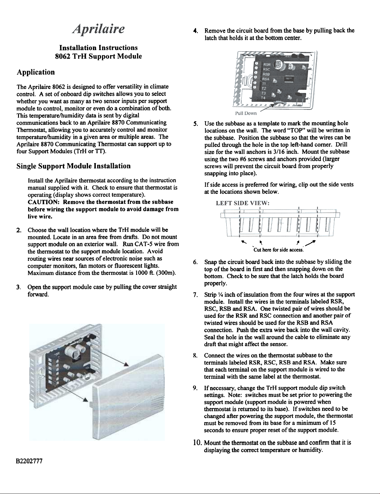
Remove the circuit board from the base by pulling back the
4.
latch that holds it at the bottom center.
Use the subbase as a template to mark the mounting hole
s.
locations on the wall. The word "TOP" will be written in
the subbase. Position the subbase so that the wires can be
pulled through the hole in the top left-hand comer. Drill
size for the wall anchors is 3/16 inch. Mount the subbase
using the two #6 screws and anchors provided (larger
screws will prevent the circuit board from properly
snapping into place).
If side access is preferred for wiring, clip out the side vents
at the locations shown below.
Choose the wall location where the TrH module will be
2.
mounted. Locate in an area free from drafts. Do not mount
support module on an exterior wall. Run CAT -5 wire from
the thermostat to the support module location. Avoid
routing wires near sources of electronic noise such as
computer monitors, fan motors or fluorescent lights.
Maximum distance from the thermostat is 1000 ft. (300m).
Open the support module case by pulling the cover straight
3.
forward.
~ ~
'Cut here for side access:
6. Snap the circuit board back into the subbase by sliding the
top of the board in first and then snapping down on the
bottom. Check to be sure that the latch holds the board
properly.
Strip '/. inch of insulation from the four wires at the support
7.
module. Install the wires in the terminals labeled RSR,
RSC, RSB and RSA. One twisted pair of wires should be
used for the RSR and RSC connection and another pair of
twisted wires should be used for the RSB and RSA
connection. Push the extra wire back into the wall cavity.
Seal the hole in the wall around the cable to eliminate any
draft that might affect the sensor.
. Connect the wires on the thennostat subbase to the
8
terminals labeled RSR, RSC, RSB and RSA. Make sure
that each terminal on the support module is wired to the
terminal with the same label at the thennostat.
. If necessary, change the TrH support module dip switch
9
settings. Note: switches must be set prior to powering the
support module (support module is powered when
thennostat is returned to its base). If switches need to be
changed after powering the support module, the thennostat
must be removed from its base for a minimum of 15
seconds to ensure proper reset of the support module.
/
~
10. Mount the thennostat on the subbase and confinn that it is
displaying the correct temperature or humidity.
B2202777
Multiple Support Module Installation
up to 4 support modules can be connected to provide
temperature or humidity averaging in a large area or for several
zones being controlled by the same system. The maximum
cumulative distance of all of the support modules from the
thermostat is IOOOft.
CAUTION: Make sure that there is no power to the
support modules by removing the thermostat from the
subbase.
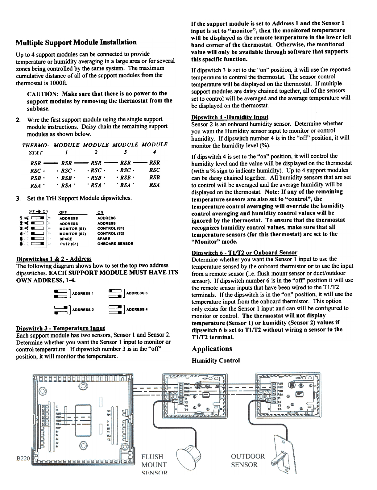
Wire the first support module using the single support
2.
module instructions. Daisy chain the remaining support
modules as shown below.
THERMO- MODULE MODULE MODULE MODULE
STAT J 2 3 4'
RSR - RSR - RSR - RSR - RSR
RSC . . RSC . . RSC . . RSC . RSC
RSB . . RSB . . RSB . . RSB . RSB
RSA . . RSA . . RSA . . RSA . RSA
Set the TrH Support Module dipswitches.
3.
~
c:==-
1~
8:=:J
2-(
~
~
""
~
...~
~
S!
c==-
8L
Dioswitches 1 & 2 - Address
The following diagram shows how to set the top two address
dips witches. EACH SUPPORT MODULE MUST HAVE ITS
OWN ADDRESS, 1-4.
Dioswitch 3 - Temoerature fnout
Each support module has two sensors, Sensor 1 and Sensor 2.
Determine whether you want the Sensor 1 input to monitor or
conb'ol temperature. If dipswitch number 3 is in the "oft"
position, it will monitor the temperature.
OFF
ADORESS
ADDRESS
MONITDR (SI)
MONITOR (S2)
SPARE
TI/T2 (SI)
~ ] ADDRESS 1
~] ADDRESS 2
~
ADDRESS
ADDRESS
CONTROL (SI)
CONTROL (S2)
SPARE
ONBOARDSENIOR
~] ADDRESS 3
~] ADDRESS 4
If the support module is set to Address 1 and the Sensor 1
input is set to "monitor", then the monitored temperature
will be displayed as the remote temperature in the lower left
hand corner of the thermostat. Otherwise, the monitored
value will only be available through software that supports
this specific function.
If dipswitch 3 is set to the "on" position, it will use the reported
temperature to control the thermostat. The sensor control
temperature will be displayed on the thermostat. If multiple
support modules are daisy chained together, all of the sensors
set to control will be averaged and the average temperature will
be displayed on the thermostat.
Dioswitch 4 -Humiditv Inout
Sensor 2 is an onboard humidity sensor. Determine whether
you want the Humidity sensor input to monitor or control
humidity. If dipswitch number 4 is in the "off" position, it will
monitor the humidity level (%).
If dipswitch 4 is set to the "on" position, it will control the
humidity level and the value will be displayed on the thermostat
(with a % sign to indicate humidity). Up to 4 support modules
can be daisy chained together. All humidity sensors that are set
to control will be averaged and the average humidity will be
displayed on the thermostat. Note: If any of the remaining
temperature sensors are also set to "control", the
temperature control averaging will override the humidity
control averaging and humidity control values will be
ignored by the thermostat. To ensure that the thermostat
recognizes humidity control values, make sure that all
temperature sensors (for this thermostat) are set to the
"Monitor" mode.
Dioswitch 6 - Tltr2 or Onboard Sensor
Determine whether you want the Sensor 1 input to use the
temperature sensed by the onboard thermistor or to use the input
from a remote sensor (i.e. flush mount sensor or duct/outdoor
sensor). If dipswitch number 6 is in the "off" position it will use
the remote sensor inputs that have been wired to the TIm
terminals. If the dipswitch is in the "on" position, it will use the
temperature input from the onboard thermistor. This option
only exists for the Sensor I input and can still be configured to
monitor or control. The thermostat will not display
temperature (Sensor 1) or humidity (Sensor 2) values if
dipswitch 6 is set to TIm without wiring a sensor to the
Tltr2 terminal.
Applications
Humidity Control
 Loading...