

Page 1
Installation Instructions
8061 TT Support Module
Application
The Aprilaire 8061 is designed to offer versatility in climate
control. A set of onboard dipswitches allows you to select
whether you want as many as two sensor inputs per support
module to control, monitor or even do a combination of both.
This temperature data is sent by digital communications back to
an Aprilaire 8870 Communicating Thermostat, allowing you to
accurately control and monitor temperature in a given area or
multiple areas. The Aprilaire 8870 Communicating Thermostat
can support up to four Support Modules (Tf or TrH).
Single Support Module Installation
Install the Aprilaire thermostat according to the instruction
manual supplied with it. Check to ensure that thermostat is
operating (display shows correct temperature).
CAUTION: Remove the thermostat from the subbase
before wiring the support module to avoid damage from
live wire.
Choose the wall location where the 1T module will be
mounted. Locate in an area free from drafts. Do not mount
support module on an exterior wall. Run CAT -5 wire from
the thermostat to the support module location. A void
routing wires near sources of electronic noise such as
computer monitors, fan motors or fluorescent lights.
Maximum distance from the thermostat is 1000 ft. (300m).
OpeD the support module case by pulling the cover straight
forward.
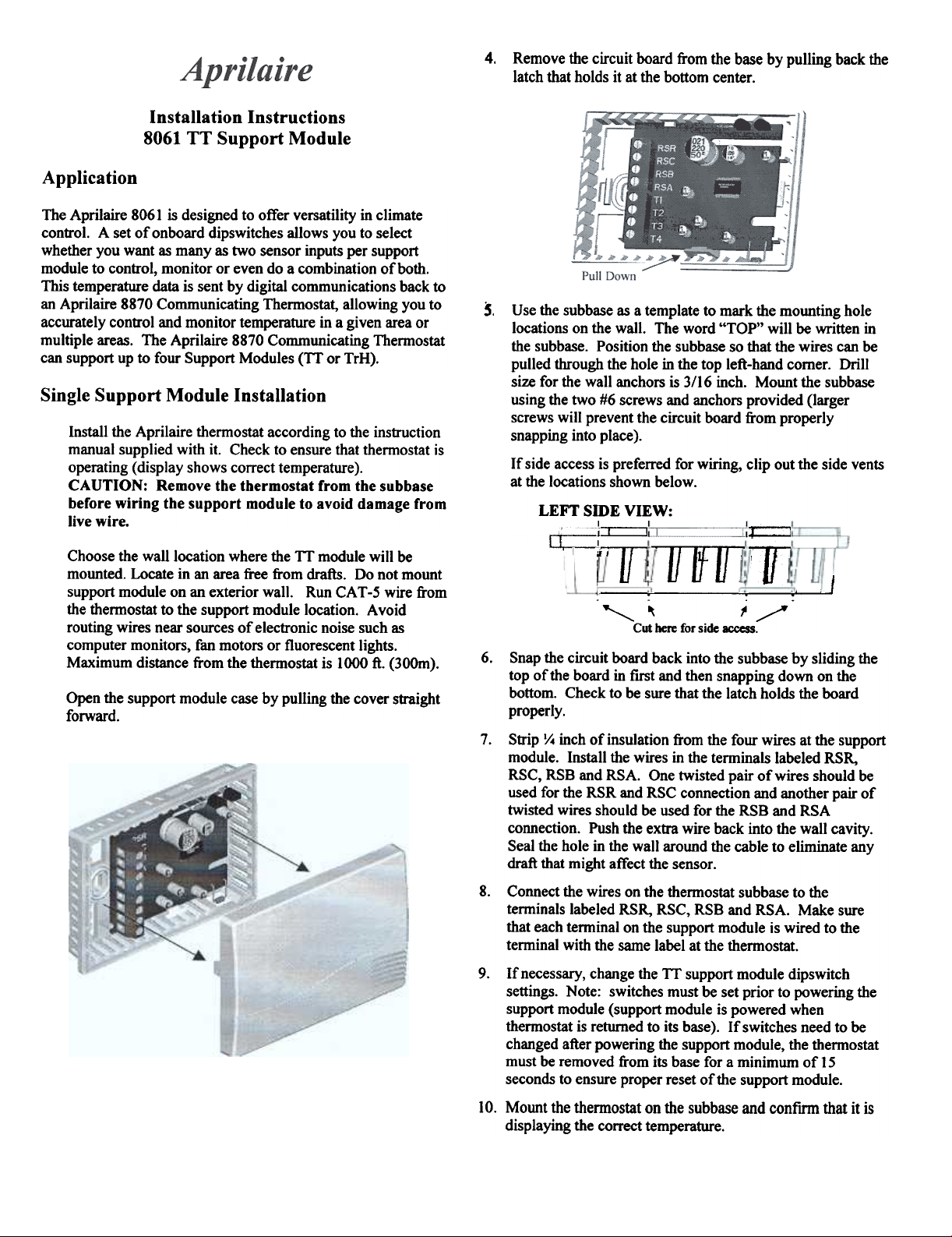
4. Remove the circuit board from the base by pulling back the
latch that holds it at the bottom center.
Use the subbase as a template to mark the mounting hole
5.
locations on the wall. The word "TOP" will be written in
the subbase. Position the subbase so that the wires can be
pulled through the hole in the top left-hand comer. Drill
size for the wall anchors is 3/16 inch. Mount the subbase
using the two #6 screws and anchors provided (larger
screws will prevent the circuit board from properly
snapping into place).
If side access is preferred for wiring, clip out the side vents
at the locations shown below.
LEFT SmE VIEW:
I I I
~
~
~
-T
T1Jff I
If] I
.. ..
,,~ ~/
Cut here for side access.
6. Snap the circuit board back into the subbase by sliding the
top of the board in first and then snapping down on the
bottom. Check to be sure that the latch holds the board
properly.
7. Strip y. inch of insulation from the four wires at the support
module. Install the wires in the terminals labeled RSR,
RSC, RSB and RSA. One twisted pair of wires should be
used for the RSR and RSC connection and another pair of
twisted wires should be used for the RSB and RSA
connection. Push the extra wire back into the wall cavity.
Seal the hole in the wall around the cable to eliminate any
draft that might affect the sensor.
8. Connect the wires on the thermostat subbase to the
terminals labeled RSR, RSC, RSB and RSA. Make sure
that each terminal on the support module is wired to the
terminal with the same label at the thermostat.
9. If necessary, change the Tf support module dipswitch
settings. Note: switches must be set prior to powering the
support module (support module is powered when
thermostat is returned to its base). If switches need to be
changed after powering the support module, the thermostat
must be removed from its base for a minimum of 15
seconds to ensure proper reset of the support module.
10. Mount the themostat on the subbase and confirm that it is
displaying the correct temperature.
Page 2
Multiple Support Module Installation
up to 4 support modules can be connected to provide
temperature averaging in a large area or for several zones being
controlled by the same system. The maximum cumulative
distance between the support modules and the thermostat is
1000 ft.
CAUTION: Make sure that there is no power to the
support modules by removing the thermostat from the
subbase.
2.
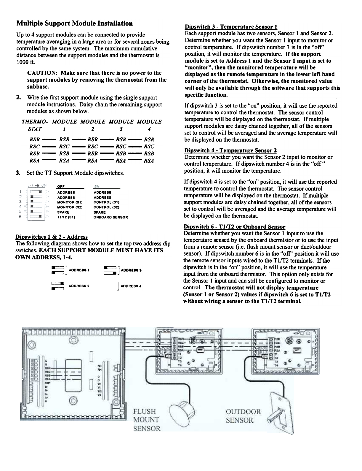
Wire the first support module using the single support
module instructions. Daisy chain the remaining support
modules as shown below.
THERMO- MODULE MODULE MODULE MODULE
STAT 1 2 3 4
RSR - RSR - RSR - RSR - RSR
RSC - RSC - RSC - RSC - RSC
RSB - RSB - RSB - RSB - RSB
RSA - RSA - RSA - RSA - RSA
3. Set dte TT Support Module dipswitches.
OFF
ADDRESS
ADDRESS
MONITOR (SI)
MONITOR (S2)
SPARE
TI/T2 (SI)
Dioswitches 1 & 2 - Address
The following diagram shows how to set the top two address dip
switches. EACH SUPPORT MODULE MUST HAVE ITS
OWN ADDRESS, 1-4.
~ ] ADDRE88 1
~ ] ADDRESS 2
ADDRESS
ADDRESS
CONTROL (SI)
CONTROL (S2)
SPARE
ON BOARD SENSOR
~] MORISS.
] ADDRESS 4
Dipswitch 3 - Temperature Sensor 1
Each support module has two sensors, Sensor I and Sensor 2.
Determine whether you want the Sensor I input to monitor or
control temperature. If dipswitch number 3 is in the "off'
position, it will monitor the temperature. If the support
module is set to Address 1 and the Sensor 1 input is set to
"monitor", then the monitored temperature will be
displayed as the remote temperature in the lower left hand
corner of the thermostat. Otherwise, the monitored value
will only be available through the software that supports this
specific function.
If dipswitch 3 is set to the "on" position, it will use the reported
temperature to control the thermostat. The sensor control
temperature will be displayed on the thermostat. If multiple
support modules are daisy chained together, all of the sensors
set to control will be averaged and the average temperature will
be displayed on the thermostat.
Dinswitch 4 - Temperature Sensor 2
Determine whether you want the Sensor 2 input to monitor or
control temperature. If dipswitch number 4 is in the "off"
position, it will monitor the temperature.
If dipswitch 4 is set to the "on" position, it will use the reported
temperature to control the thermostat. The sensor control
temperature will be displayed on the thermostat. If multiple
support modules are daisy chained together, all of the sensors
set to control will be averaged and the average temperature will
be displayed on the thermostat.
Dioswitch 6 - TIff2 or Onboard Sensor
Determine whether you want the Sensor 1 input to use the
temperature sensed by the onboard thermistor or to use the input
from a remote sensor (i.e. flush mount sensor or duct/outdoor
sensor). If dipswitch number 6 is in the "off' position it will use
the remote sensor inputs wired to the TIm terminals. If the
dipswitch is in the "on" position, it will use the temperature
input from the onboard thermistor. This option only exists for
the Sensor 1 input and can still be configured to monitor or
control. The thermostat will not display temperature
(Sensor 1 or Sensor 2) values if dipswitch 6 is set to TIff2
without wiring a sensor to the TIm terminal.
Page 3

Applications
Heat Pump Applications
If the support module is being used with a heat pump thermostat
with auxiliary heat, the thermostat can be configured to disable
the use of auxiliary heat during warm weather and to lock out
the compressor when the outdoor temperature is too cold. This
allows for the most efficient use of energy.
At warmer temperatures, a heat pump will operate much more
efficiently than the auxiliary heat. It can save energy to disable
auxiliary heat in some cases, for example, when returning from
a setback on a mild day. The temperature above which auxiliary
heat is disabled is the auxiliary lockout temperature or high
balance point. Refer to the thermostat user manual for a
detailed explanation.
Air-to-air heat pumps become less efficient as the outdoor
temperature drops. The temperature at which it becomes more
efficient to use auxiliary heat instead of the heat pump is the
balance point or low balance point Refer to thermostat user
manual for a more detailed explanation.
Configure the temperature sensor (TIm) that you are using to
sense outdoor temperature to the "Monitor" mode by setting the
dipswitch 3 to the "off' position and the support module address
to number 1. The high and low balance points are set at the
thermostat. Refer to the thermostat Installation Instructions for
more details.
Specifications
Power Supply: 18 to 30 V AC or DC (24 V Nominal)
Maximum Relative Humidity: 90% (non-condensing)
Max. Cable Length Between Module and TSTAT: lOOOft
The maximum cumulative distance between multiple
support modules and the thennostat is 1000 ft.
Max. Cable Length Between Module and Remote
Temperature Sensor: 300ft
T em~rature
Accuracy:
Comfort Range (60°F - 80°F): % 1°F
Control Range (40°F-100°F): %2°F
Operating Range (-40°F - 185°F): % 3°F
Maximum Display Range: -40°F - 18soF
Troubleshooting
Thermostat has no display: Check 24 V AC supply. Check
for incorrect wiring between the thermostat and support module.
Incorrect wiring can damage the thermostat and transformer or
blow a fuse in the equipment. If more than one support module
is used, make sure that each one has a unique address.
Thermostat displays very high temperature: Ensure that
dipswitch 6 is set properly. If dipswitch 6 is set to TIm and a
sensor has not been wired to the TIm terminal, no temperature
(Sensor I or Sensor 2) readings will be displayed. Also, if
dipswitch 6 is set to onboard and a sensor has been wired to the
TIm terminal, incorrect temperature readings will be
displayed. Check wires on remote sensors (flush mount or
outdoor/duct) to ensure that they are not touching. If they are,
separate them.
Thermostat displays very low temperature: Remote sensor
(flush mount or outdoor/duct) is not connected to sensor
properly. Check wiring.
Thermostat doesn't display remote temperature: Make sure
that the support module is set to address 1. Reset support
module after changing any dipswitches by turning off power for
15 seconds.
 Loading...