

Aprilaire 8028 User Manual
1. 120 volts may cause serious injury from electrical shock. Leave
power to all system components disconnected until installation
is complete
WARNING
MODEL 8028 DAMPER POWER DISTRIBUTION PANEL
INSTALLATION INSTRUCTIONS & APPLICATION SHEET
1. Installation must be done in accordance with the NEC and all
other applicable local codes.
2. To prevent excessive transformer heating, do not power more
than the recommended number of dampers to a transformer.
CAUTION
Voltage 24 VAC ±20%
Max. Damper Power Input per Zone 100VA max @ 24 VAC
Damper Fuse Size 5A Fast Acting (spare supplied)
Control Input Current Draw (Zone A and Zone B) 50 mA @ 24 VAC
Max. No. of Aprilaire Dampers per Zone 10 (refer to Diagram 3 on the back if there are
more than 10 dampers in a zone)
Max Wire Size 18 AWG
Application Temperature/RH 158°F / 90% RH (non-condensing)
SPECIFICATIONS
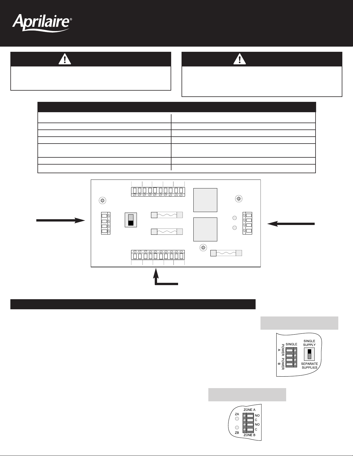
SWITCH SETTINGS AND LED’S
Set to SINGLE SUPPLY when used:
• in a two zone system when there are no more than 10 dampers in either ZONE A or ZONE B.
Size the transformer for the zone with the most dampers.
• when there are no more than 10 total dampers wired to ZONE A plus ZONE B. Size the transformer
for the total number of dampers connected to both zones.
When set to SINGLE SUPPLY, wire transformer to “POWER A” terminals. Refer to Diagram 2 on the
back for wiring.
Set to SEPARATE SUPPLIES for all other applications. Wire transformers to “POWER A” and “POWER B”
terminals. Refer to Diagram 1 on the back.
Damper Power Input(s)
from Transformers
Dampers Wired to ZONE A and ZONE B Terminals
Control Input(s) from
Zoned Comfort Control
Panel
Power Supply Switch
Zone LED’s
ZA LED lights when 24-volts is applied to the ZONE A control input.
ZB LED lights when 24-volts is applied to the ZONE B control input.
54 32 1
ZONE A
DAMPERS
POWER
A
POWER
B
SINGLE
SINGLE
SUPPLY
SEPARATE
SUPPLIES
ZONE A – 5 AMP
ZONE B – 5 AMP
ZA
ZB
ZONE A
ZONE B
NO
C
NO
C
ZONE B
DAMPERS
12345
SPARE FUSE – 5 AMP
PO Box 1467 • Madison, WI 53701-1467 • Phone 800/334-6011 • Fax 608/257-4357 • www.aprilairecontractor.com
©2005 Research Products Corporation
Printed in USA
10006652 08.05
B2203856A
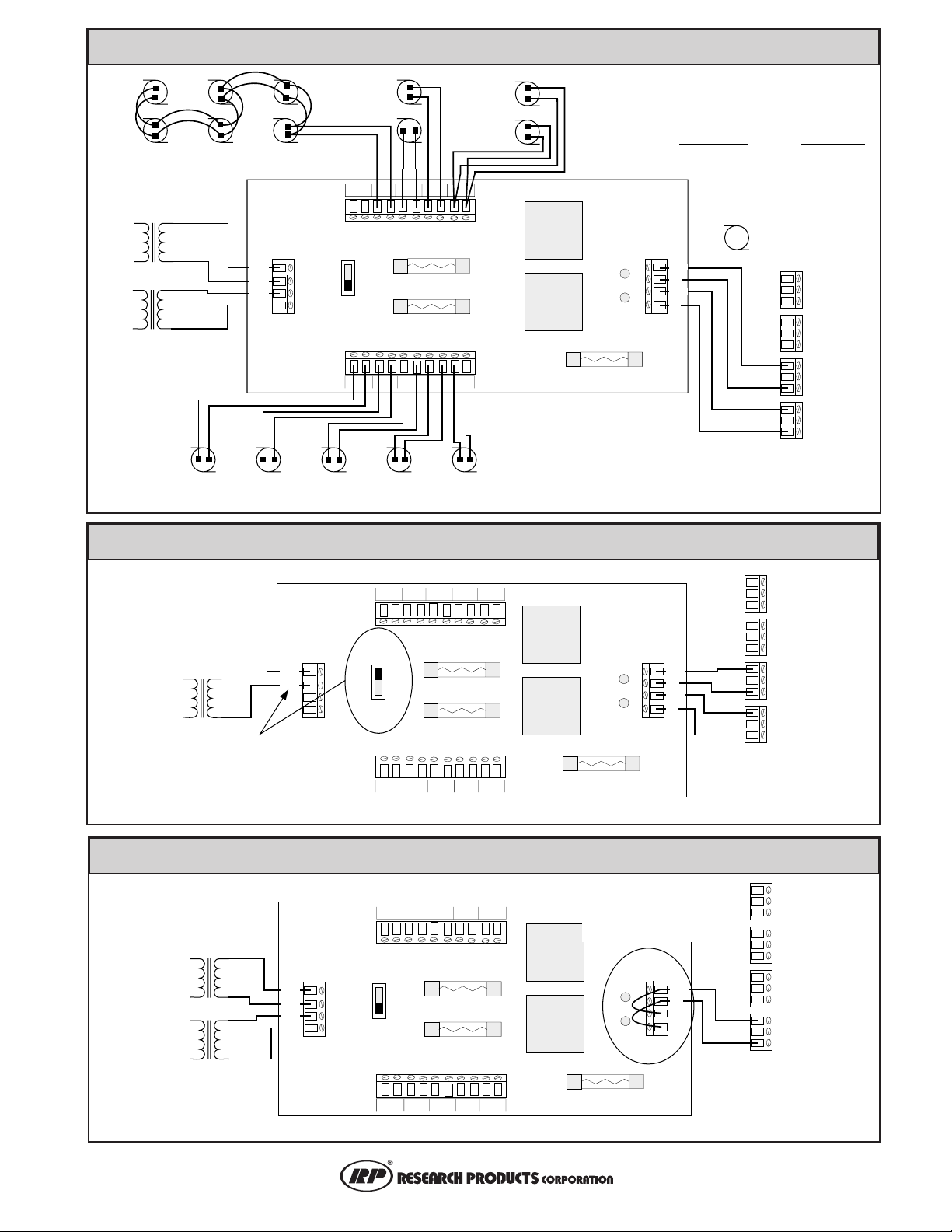
DIAGRAM 1 - Two Transformers Serving Two Zones
DIAGRAM 2 - One Transformer Serving Two Zones
DIAGRAM 3 - Two Transformers Serving One Zone
ZONE A DAMPER
(“daisy chain” wiring)
TRANSFORMER
SIZE FOR TOTAL NUMBER OF
DAMPERS WIRED TO ZONE A
DAMPER OUTPUTS
120
VAC
120
VAC
ZONE B DAMPER
TRANSFORMER
SIZE FOR TOTAL NUMBER OF
DAMPERS WIRED TO ZONE B
DAMPER OUTPUTS
24
VAC
24
VAC
ZONE A
DAMPERS
POWER
SINGLE
A
POWER
B
ZONE B
DAMPERS
ZONE 1 DAMPERS
(“home run” wiring)
54 32 1
SINGLE
SUPPLY
SEPARATE
SUPPLIES
ZONE A – 5 AMP
ZONE B – 5 AMP
12345
8028 DAMPER POWER
DISTRIBUTION PANEL
ZONE 2
DAMPERS
ZA
ZB
SPARE FUSE – 5 AMP
DAMPER TRANSFORMER
SIZING
TRANSFORMER MAX. NO. OF
VA RATING
DAMPERS
40 VA 4
50 VA 5
75 VA 7
100 VA 10
DAMPER
ZONE A
ZONE B
NO
C
NO
C
MOTOR
ZONE 4
DAMPER
COM NC NOCOM NC NOCOM NC NOCOM NC NO
ZONE 3
DAMPER
ZONE 2
DAMPER
ZONE 1
DAMPER
ZONE PANEL
WIRE ZONE PANEL ACCORDING
TO THE INSTRUCTIONS PROVIDED
WITH THE ZONE PANEL
DAMPER
TRANSFORMER
TWO ZONE SYSTEMS:
SIZE USING THE ZONE WITH
THE MOST DAMPERS
SYSTEMS W/MORE THAN 2
ZONES:
SIZE USING TOTAL
DAMPERS IN BOTH ZONES
120
VAC
24
VAC
SET SWITCH
FOR SINGLE
SUPPLY AND
WIRE TO SINGLE
(POWER A)
INPUTS
ZONE A DAMPER
TRANSFORMER
SIZE FOR TOTAL NUMBER OF
DAMPERS WIRED TO ZONE A
DAMPER OUTPUTS
120
VAC
120
VAC
ZONE B DAMPER
TRANSFORMER
SIZE FOR TOTAL NUMBER
OF DAMPERS WIRED TO
ZONE B DAMPER OUTPUTS
24
VAC
24
VAC
WIRE DAMPERS AS SHOWN IN DIAGRAM 1
54 32 1
ZONE A
DAMPERS
ZONE B
DAMPERS
SINGLE
SUPPLY
SEPARATE
SUPPLIES
ZONE A – 5 AMP
ZONE B – 5 AMP
ZONE A
ZA
ZB
12345
SPARE FUSE – 5 AMP
ZONE B
NO
C
NO
C
POWER
A
POWER
B
SINGLE
8028 DAMPER POWER DISTRIBUTION PANEL
WIRE DAMPERS AS SHOWN IN DIAGRAM 1
INSTALL JUMPERS
BETWEEN ZONE A AND
ZONE B INPUTS
ZONE A
ZA
ZB
ZONE B
SPARE FUSE – 5 AMP
NO
C
NO
C
POWER
A
POWER
B
SINGLE
ZONE A
DAMPERS
ZONE B
DAMPERS
54 32 1
SINGLE
SUPPLY
SEPARATE
SUPPLIES
ZONE A – 5 AMP
ZONE B – 5 AMP
12345
8028 DAMPER POWER DISTRIBUTION PANEL
ZONE 4
DAMPER
COM NC NOCOM NC NOCOM NC NOCOM NC NO
ZONE 3
DAMPER
ZONE 2
DAMPER
ZONE 1
DAMPER
ZONE PANEL
WIRE ZONE PANEL
ACCORDING TO THE
INSTRUCTIONS PROVIDED
WITH THE ZONE PANEL
ZONE 4
DAMPER
COM NC NOCOM NC NOCOM NC NOCOM NC NO
ZONE 3
DAMPER
ZONE 2
DAMPER
ZONE 1
DAMPER
ZONE PANEL
WIRE ZONE PANEL
ACCORDING TO THE
INSTRUCTIONS
PROVIDED WITH THE
ZONE PANEL
 Loading...