

Aprilaire 8022 Installation Manual
Model 8022
3 to 4 Wire Adapter Installation Instructions
IMPORTANT
Read entire instructions before installing the 3 to 4 wire adapter.
SAFETY CONSIDERATIONS
Read and follow manufacturer instructions carefully. Follow all local
electrical codes during installation. All wiring must conform to local and
national electrical codes. Improper wiring or installation may damage
the 3 to 4 wire adapter or HVAC equipment.
Recognize safety information. This is the safety alert symbol.
When the safety alert symbol is present on equipment or in the
instruction manual, be alert to the potential for personal injury.
Understand the signal words DANGER, WARNING, and CAUTION. These
words are used with the safety alert symbol. DANGER identifies the
most serious hazards which will result in severe personal injury or death.
WARNING signifies a hazard that could result in personal injury or
death. CAUTION is used to identify unsafe practices which would result
in minor personal injury or property damage.
GENERAL
In applications where additional wiring cannot be run, the 3 to 4 wire
adapter can be used to add a wire to the thermostat. The adapter is
also used to fix a broken wire, or add a common wire to a 4-wire system
(the green and yellow wires of the Diode ‘Y’ may not be connected to
the R or C terminal of the thermostat).
INSTALLATION
STEP 1 – LOCATION
The 3 to 4 wire adapter can be mounted inside the HVAC unit or inside
the control box. The 3 to 4 wire adapter should not be installed in a
location where the adapter or wiring may be exposed to the elements.
Wires running from adapter are 9" long. 3 to 4 wire adapter should be
within 9" of thermostat connections to HVAC terminal block.
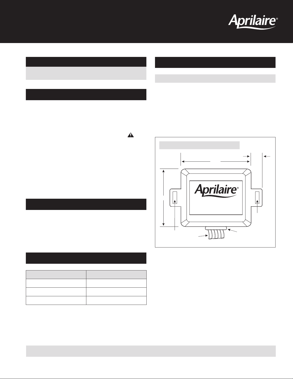
If required, mount the 3 to 4 wire adapter with 2 screws (not provided).
See Figure 1.
FIGURE 1 – 3 TO 4 WIRE ADAPTER MOUNTING
3/8"
2-1/8"
1-3/4"
3 to 4 Wire
ADAPTER
MOUNTING
HOLE
MOUNTING
HOLE
WIRING
GROMMET
CONTENTS
CONTENTS QUANTITY
3 to 4 Wire Adapter 1
Diode ‘Y’ 1
Wire Nuts 2
READ AND SAVE THESE INSTRUCTIONS
STEP 2 – WIRING REQUIREMENTS
The 3 to 4 wire adapter wiring has the following requirements:
1. All system wiring must be in compliance with all applicable local and
national codes.
2. All wiring should be color coded in conformance with standard
recommendations.
3. All wiring should be 18- 22-gauge, unshielded wire. The Maximum
distance between the adapter and the thermostat for 18-gauge wire
is 100 feet. The maximum distance between the adapter and the
thermostat for 22-gauge wire is 36 feet.
STEP 3 – ADAPTER WIRING
WARNING
Before installing the 3 to 4 wire adapter, turn o all power to the
HVAC system. There may be more than one power disconnect.
Electrical shock can cause injury or death.
Depending on the application and the usage of the 3 to 4 wire adapter,
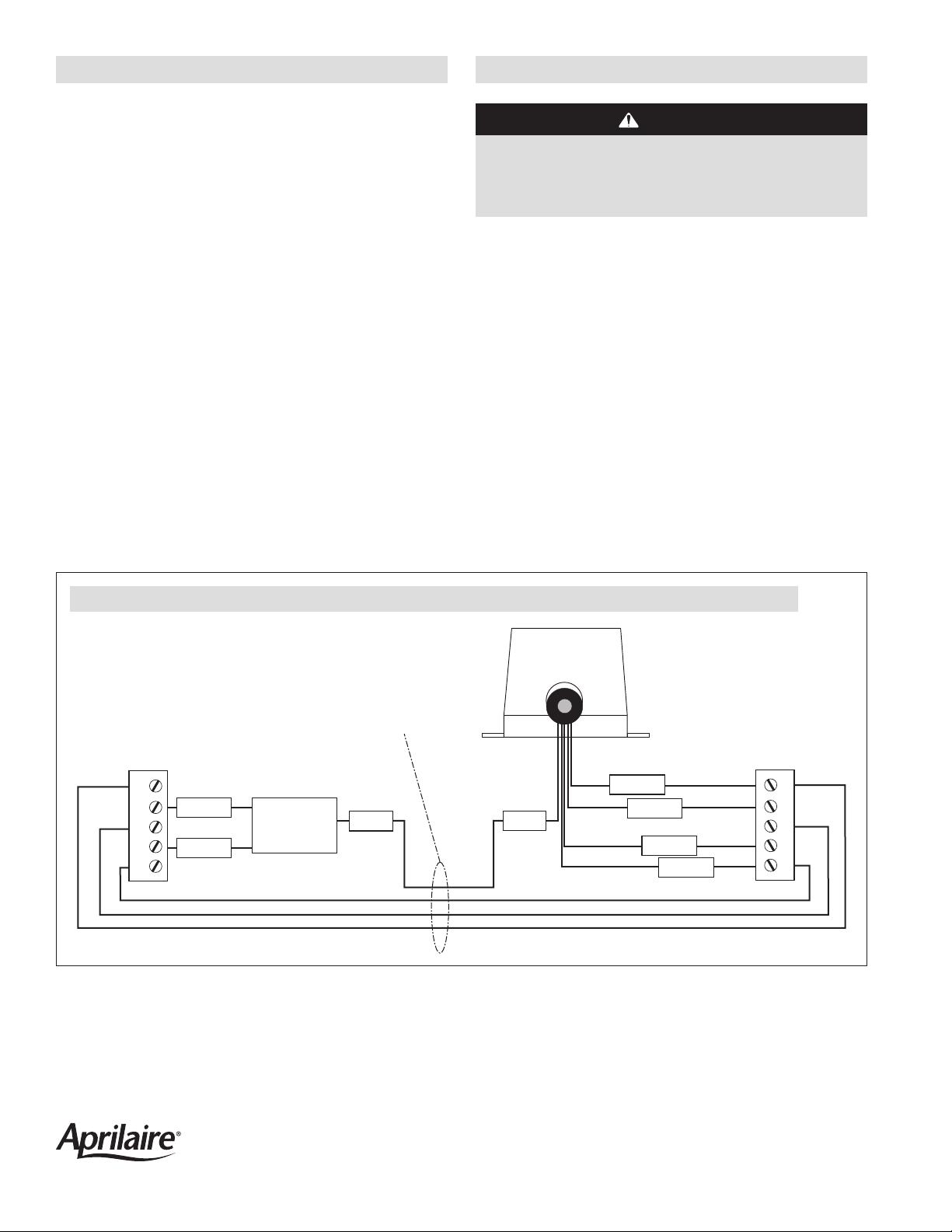
wiring will vary. Refer to the wiring diagram, Figure 2.
• The BLUE wire of the 3 to 4 wire adapter must always be connected
to the BLUE wire of the Diode ‘Y’.
• DO NOT connect the 3 to 4 wire adapter BLUE, GREEN, or YELLOW
wires to the R and C terminals of the HVAC unit, damage may result.
• The GREEN and YELLOW wires of the Diode ‘Y’ should be regarded as
extensions of the yellow and green wires of the 3 to 4 wire adapter.
The YELLOW wire on the 3 to 4 wire adapter must be connected to Y
on the HVAC unit to control cooling. The GREEN wire on the 3 to 4 wire
adapter must be connected to G on the HVAC unit to control the fan.
• Use the wire nuts for wire connections to the Diode ‘Y’.
• Do not connect the green and yellow wires of the Diode ‘Y’ to the R or
C terminal of the thermostat.
FIGURE 2 – WIRING DIAGRAM – 4 EXISTING WIRES WITH 3 TO 4 WIRE ADAPTER TO ACCOMMODATE A THERMOSTAT THAT REQUIRES 5 WIRES
3 to 4 Wire
ADAPTER
FOUR EXISTING
THERMOSTAT WIRES
THERMOSTAT
R
G
W
Y
C
GREEN
YELLOW
3 to 4 Wire
ADAPTER
Diode ‘Y’
BLUE
RED
GREEN
BLUE
YELLOW
BROWN
HVAC
R
G
W
Y
C
AprilairePartners.com
P.O. Box 1467 Madison, WI 53701-1467
800-334-6011 F: 608-257-4357
©2016 Aprilaire – A division of Research Products Corporation
61001279 B2206866A 1.16
 Loading...