

Page 1

Xserve
User’s Guide
Includes setup, expansion,
and hardware specifications for Xserve
Page 2

K
Apple Computer, Inc.
©
2002 Apple Computer, Inc. All rights reserved.
Under the copyright laws, this manual may not be copied, in whole or in part, without the written consent of Apple.
Your rights to the software are governed by the accompanying software license agreement.
The Apple logo is a trademark of Apple Computer, Inc., registered in the U.S. and other countries. Use of the
“keyboard” Apple logo (Option-Shift-K) for commercial purposes without the prior written consent of Apple may
constitute trademark infringement and unfair competition in violation of federal and state laws.
Every effort has been made to ensure that the information in this manual is accurate. Apple is not responsible for
printing or clerical errors.
Apple Computer, Inc.
1 Infinite Loop
Cupertino, CA 95014-2084
408-996-1010
www.apple.com
Apple, the Apple logo, FireWire, the FireWire logo, Mac, Macintosh, and QuickTime are trademarks of Apple
Computer, Inc., registered in the U.S. and other countries.
Xserve is a trademark of Apple Computer, Inc.
PowerPC and the PowerPC logo are trademarks of International Business Machines Corporation, used under
license therefrom.
This product includes software developed by the University of California, Berkeley, and its contributors.
Other company and product names mentioned herein are trademarks of their respective companies. Mention of
third-party products is for informational purposes only and constitutes neither an endorsement nor a
recommendation. Apple assumes no responsibility with regard to the performance or use of these products.
Simultaneously published in the United States and Canada.
Page 3

Contents
Preface Introducing Xserve 7
1 Xserve Overview 9
Your Server at a Glance—Front Panel 10
Your Server at a Glance—Back Panel 12
Your Server at a Glance—Interior 14
Your Server at a Glance—Mounting Hardware 16
2 Preparing to Install Your Server 19
Guidelines for Server Installation 19
Choose the Server’s Position in a Rack 19
Electrical Power 20
Operating Environment 21
Rack Stability 21
Considerations for Cables 21
Security 22
3 Installing Your Server in a Rack 23
Installing the Server 24
Get Ready to Install 24
Prepare the Server for Installation 25
Install the Server in a Four-Post Rack or Cabinet 29
Install the Cable-Management Arm 33
Place the Server in the Rack 36
Install the Server in a Two-Post (Telco) Rack 37
Connect Cables to the Server 40
3
Page 4

Preparing the Server for Software Setup 43
4 Using Your Server 45
Starting Up the Server 45
Monitoring Status Lights and Other Indicators on the Server 46
If the Server Has a Problem 46
What to Do If . . . 47
5 Installing or Replacing Server Components 49
Installing or Replacing an Apple Drive Module 50
Opening and Closing the Server 52
Adding Memory 56
Installing a PCI Card 59
About PCI Cards for the Server 59
Install a PCI Card in a Long Card Slot 60
Install a PCI Card in the PCI/AGP Card Slot 64
Replacing the Battery 67
Appendix A Specifications 69
Processor and Memory Specifications 69
Dimensions and Operating Environment 69
CD-ROM Specifications 70
Ethernet Specifications 70
FireWire Specifications 70
USB Specifications 70
Serial Port Specifications 71
Video Card Specifications 71
Power Supply 71
Power Requirements for Devices You Can Connect 72
System Clock and Battery 72
Appendix B Safety, Maintenance, and Ergonomics 73
Important Safety Information 73
Handling Your Computer Equipment 74
Protecting Your CD Drive 75
4
Contents
Page 5

Power Supply 75
Cleaning Your Equipment 75
Cleaning the Server’s Case 75
Apple and the Environment 76
For More Information 76
Health-Related Information About Computer Use 76
Contents
5
Page 6

Page 7

PREFACE
Introducing Xserve
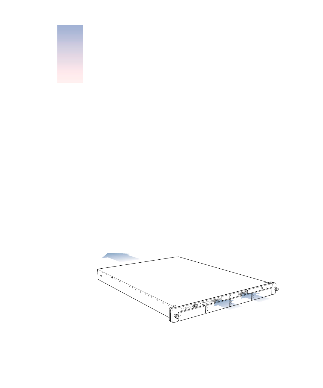
Congratulations on purchasing your new server. This product is designed to be mounted in a
rack. Once the server is installed in the rack, an administrator or other user can slide it open
from the front to exchange or add components.
Among the distinctive hardware features of the server are
m
one or two G4 processors with minimum operating speed of 1 gigahertz (GHz), with 256
kilobytes (K) of level 2 cache and 2 megabytes (MB) of double-data-rate (DDR) backside
L3 cache
m
up to 2 gigabytes (GB) of DDR Synchronous Dynamic Random-Access Memory (SDRAM)
m
system bus speed 133 megahertz (MHz) (at minimum)
m
four Apple Drive Module bays, supporting up to four hot-pluggable ATA 100 hard disks,
accessible from the front, with status and activity lights
m
front panel with CD-ROM drive; LED status lights; power and system identifier buttons
and lights; FireWire port; and security lock for the enclosure
m
back panel with one or two gigabit Ethernet ports (auto-negotiating 10/100/1000 megabits
per second); two FireWire ports; two USB ports; serial port that supports RS-232 or
RS-422 connection; and VGA monitor connection
m
cable-management arm to allow the unit to be opened without disconnecting cables
m
two internal expansion slots for PCI cards and one combination slot for either a PCI or an
AGP card
m
fault-sensing operation, with sensors to detect internal temperature, blower status or
failure, power status or failure, and open enclosure
7
Page 8

Among the services offered by Mac OS X Server, included with the standard configuration, are
m
file and print services for Macintosh, Windows, and UNIX® clients
m
high-performance Apache Web server, with integrated WebDAV and SSL
m
World Wide Web application deployment platform
m
QuickTime Streaming Server
m
IP filtering, DHCP, DNS, and SLP networking services
m
directory services
m
mail service
m
Macintosh Management service
m
NetBoot server for Macintosh client computers that can start up from a server
m
tools for remote server configuration and monitoring
For detailed information about Mac OS X Server and instructions for using it with Xserve, see
the other documentation that came with the server. The booklet
Quick Start for Xserve
provides an overview of those materials and their contents.
8
Preface
Page 9

CHAPTER
1
Xserve Overview
1
The illustrations on the pages that follow provide a reference for the server. (Depending
on the configuration of your server, it may look slightly different from the illustrations
shown here.)
See Chapter 3, “Installing Your Server in a Rack,” on page 23 for details on the mounting
hardware and the server’s enclosure and components.
See Chapter 4, “Using Your Server,” on page 45 for details on monitoring the lights and other
indicators on the server’s front and back panels.
See Chapter 5, “Installing or Replacing Server Components,” on page 49 for details on
working with the drive modules and internal components of the server.
9
Page 10
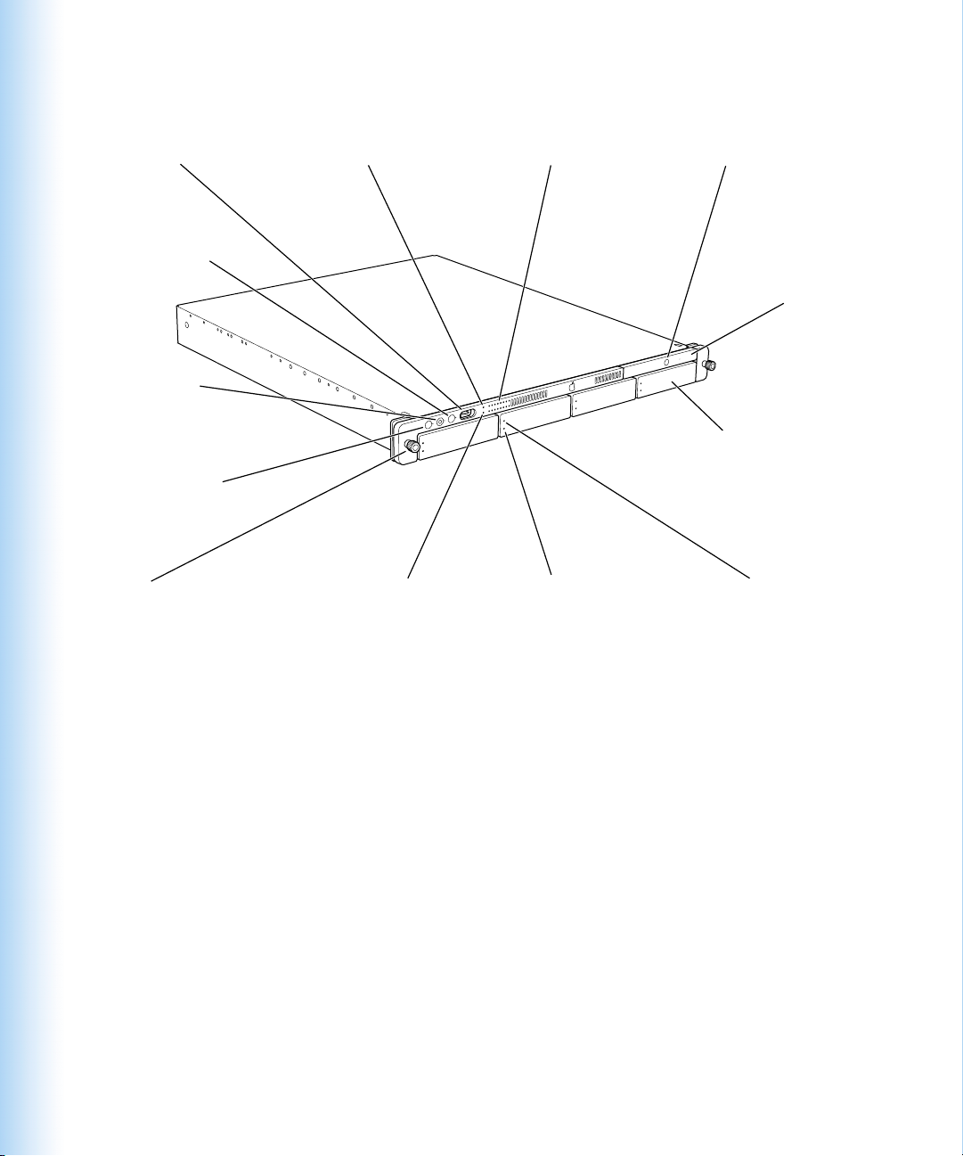
Your Server at a Glance—Front Panel
FireWire port
System identifier
button/light
Enclosure lock
and status light
Power button /light
Securing
thumbscrews (2)
Ethernet card
link light
Built-in Ethernet
link light
System activity lights
Drive module
activity light
CD drive Open button
CD drive
Apple Drive Modules bays (4)
Drive module
status light
10
Chapter 1
Page 11

Power button and light
®
Press to turn on the server.
Enclosure lock and lock status light
The lock secures the enclosure and drive modules in the server. It can be locked and
unlocked with the enclosure key supplied with the server.
System identifier button and light
The system identifier light turns on if a problem is detected. It also can be turned on
manually by pressing the button. This indicator is useful for locating a particular unit in a
rack with multiple servers. A duplicate system identifier button and light are on the back
panel.
FireWire port
Provides a FireWire connection on the front of the server. There are also two FireWire ports
on the back panel.
Ethernet link lights
Two lights indicate Ethernet links. The upper light represents a network card; the lower
light represents built-in Ethernet.
System activity lights
Two rows of eight lights indicate system activity. In a server with a single processor, the
rows of system activity lights operate in sync; in a dual-processor server, the rows of lights
operate independently to show each processor’s activity.
CD drive
You can use the tray-load CD-ROM optical drive to add or reinstall software on the server.
CD drive Open button
C
When the server is turned on, pressing this button opens the drive’s tray.
Drive modules and lights
You can install up to four drive modules in the server. These modules can be removed and
installed while the server is running. (See “Installing or Replacing an Apple Drive Module”
on page 50 for more information.) Each drive module has lights showing operating status
and disk activity.
Xserve Overview
11
Page 12
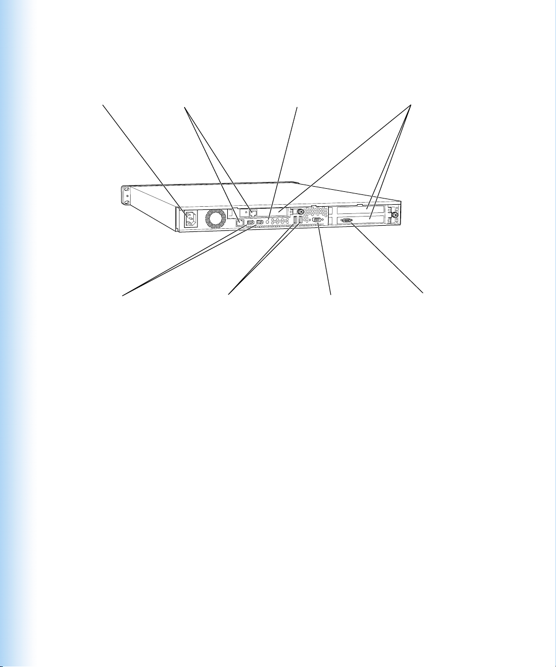
Your Server at a Glance—Back Panel
Gigabit Ethernet port(s) System identifier button/lightPower socket
FireWire ports (2) VGA monitor portSerial console port
USB ports (2)
PCI card expansion slots (3)
12
Chapter 1
Page 13

Power socket
≤
The power cord connects here; it is held in place by a special clip so that it stays connected
when the server is opened in the rack.
System identifier button and light
The system identifier light turns on if a problem is detected. It also can be turned on
manually by pressing the button. This indicator is useful for locating a particular unit in a
rack with multiple servers. A duplicate system identifier button and light are on the front
panel.
Gigabit Ethernet port
G
Connect your server to a high-speed Ethernet network. Ethernet ports adjust automatically
to the transmission speed supported by network components. One port is built in; some
configurations also have an Ethernet card installed, providing a second port.
FireWire ports
Connect FireWire devices to the server. A third FireWire port is located on the front panel.
USB ports
Connect USB devices, such as a keyboard or mouse.
Serial console port
Connect a serial device or computer with a serial port. This console supports both RS-232
and RS-422 connections.
PCI card slots and PCI/AGP card slot
You can install two 12-inch PCI cards in the server to connect peripheral devices. See “About
PCI Cards for the Server” on page 59 for details. One or two slots may come with cards
installed at the factory. One additional slot takes a 7-inch PCI card or, in some configurations,
an Accelerated Graphics Port (AGP) card. The AGP card requires a special adapter.
VGA monitor port
™
Connect a VGA monitor to the server for setup or monitoring tasks. The VGA port is on a
card installed in the server. (In some configurations, the card may be in a different slot and
may have a different connector.)
Xserve Overview
13
Page 14
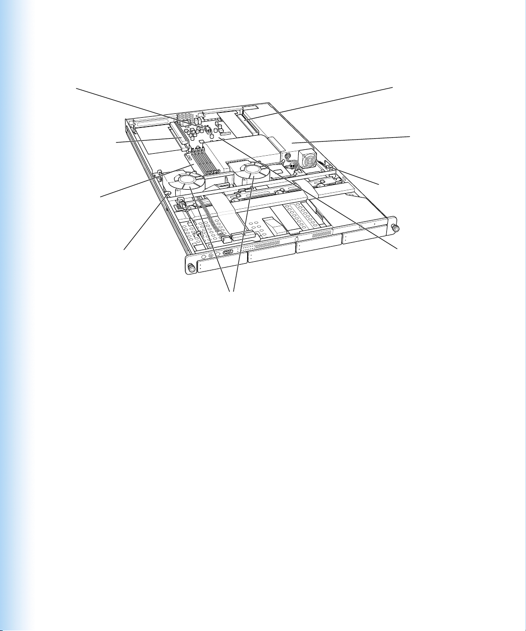
Your Server at a Glance—Interior
PCI/AGP card slotBattery
PCI card slots (2)
Chassis release latch
RAM slots (4)
Chassis release latch Main logic board
Blowers
Power supply
14
Chapter 1
Page 15

PCI card slots and PCI/AGP card slot
You can install PCI expansion cards in the three slots. The two slots on the left side of the
server hold 12-inch cards; the slot on the right side holds a 7-inch card, and can also be
configured to hold an AGP card, which requires a special adapter.
RAM expansion slots
You can expand DDR RAM up to 2 GB, using the four slots. (See “Adding Memory” on
page 56 for more information.)
Power supply
The autoswitching power supply detects the voltage and adjusts for it. This component has
a sensor that detects and reports if the power supply needs service.
Blowers
The blowers cool the server during operation. Sensors detect and report if a blower needs
service.
Chassis release latches
Press these latches to slide the server to its full length when in the rack, or to remove it
from the cover.
Xserve Overview
15
Page 16
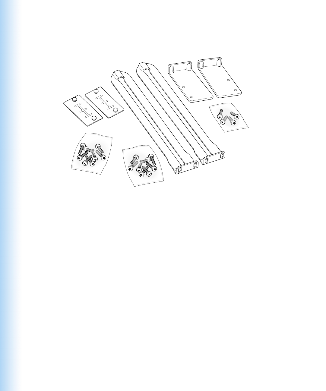
Your Server at a Glance—Mounting Hardware
A
Four-post brackets
ttachment screws (English)
Four-post braces
Attachment screws (Metric)
Two-post brackets
Two-post bracket
screws
16
Chapter 1
Page 17

Four-post brackets
Two rivets on each bracket secure it to the brace and the server’s cover.
Four-post braces
These two long, U-shaped pieces support the back of the server and attach it to the rack.
Two-post brackets
These two short, L-shaped brackets attach to the sides of the server’s enclosure and to
the rack.
Screws for attaching brackets and braces to the rack and server cover
Two sets of screws are provided; one set (English) has a diameter of 10/32 inches; the
other is metric size M5.
1
See Chapter 3, “Installing Your Server in a Rack,” on page 23 for more information on mounting hardware.
1
Xserve Overview
17
Page 18

Page 19
CHAPTER
2
Preparing to Install Your Server
2
Before you install the server in a rack, you should carefully consider the placement of the unit
in its rack and several factors in the infrastructure that will keep the server operating efficiently.
Guidelines for Server Installation
To ensure safe and smooth operation of your server, it’s essential that you plan for proper
location of the server in its rack, adequate power to the components in the rack, and the
appropriate operating environment for the rack.
As you plan for server installation, follow these guidelines to ensure that the server and its
environment are safely and appropriately positioned for efficient operation and service.
Choose the Server’s Position in a Rack
When determining the location for the server in a rack, be sure to allow adequate space for
airflow and servicing from both the front and back.
m
Air to cool the server flows from front to back. Do not cover the front or back of the
server or any of the openings in the server’s front and back panels and case.
Do not block
the air flowing
through the server.
19
Page 20

m
The server slides out of the rack from the front. Be sure to leave a minimum of 36 inches
clear in front of the server to allow room to open and service it.
m
To provide access to the server’s back panel and cables, leave at least 24 inches clear
behind the server.
m
If you are installing multiple servers or other components in the rack, place the server so
that you can easily open and service it. For example, in a multiple-component installation,
the heaviest items—such as an uninterruptible power supply—are usually placed at or
near the bottom of a rack; servers are often located near the middle of the rack.
m
For a rack with multiple components, you may want to prepare a list of all equipment in
the rack and the requirements for each unit. Such a list should include the following
information:
Component
Server 1
Server 2
Component 3
Electrical Power
Power
needed
Clear area
front/back
Height
in rack
Temperature
range
Other
If you plan to install the server in a rack that contains other components, be sure that the
circuitry and power connections are sufficient for the combined power needs of all
components. To plan for safe and adequate power to the server, follow these guidelines:
m
Check the documentation for all components in the rack to determine their power
requirements. Also determine that the available power supply for the rack is sufficient for
the planned components.
m
If you need assistance in determining the power needs of the components in the rack,
consult an electrical expert who is familiar with your facility.
Important
When planning for electrical power, make sure you have more power than
specified for all components. Also make certain that the power load is distributed evenly
among circuits to the rack’s location. Consult an electrician or other expert if you need
assistance with planning for the power needs of your components.
m
Make sure that the power connections for the server and all other components are
grounded (according to local and national standards). Consult an electrician if you need
assistance with grounding.
m
See Appendix A, “Specifications,” for more information about electrical power
requirements for the server.
20
Chapter 2
Page 21

Operating Environment
The operating environment for the server’s rack must meet certain requirements:
m Verify that the temperature range of the rack’s location is within the limits established for
the server and all other components.
m Make certain that the rack’s location has adequate ventilation to maintain the necessary
temperature range. This is particularly important for a rack that is enclosed in a cabinet.
m If multiple components are installed in the rack, consider additional cooling to assure
efficient operation of the servers and other equipment.
Rack Stability
The rack must be stable and strong enough to hold the components installed.
m Check the documentation for the rack to make certain that it can carry the load of
components.
m If you are using a two-post (telco) rack, verify that the rack is securely fastened to the
building’s structure at the top and bottom.
m Make certain that all components are secured in the rack.
m When working with components in the rack, never extend more than one at a time.
Considerations for Cables
For optimal efficiency in server operation and maintenance, follow these guidelines for
handling cables connected to the server and other components in a rack.
m Plan to install the cable-management arm supplied with the server. If you don’t install this
device, you must disconnect all cables from the server’s back panel before opening the
server in the rack.
m Arrange all component cables so that they do not interfere with access to the rack. Ideally
each component should have a cable-management option in place so that anyone
servicing units in the rack can readily determine where each cable is connected.
m To ensure full signal strength for Ethernet, serial, and other connections, make sure cables
do not exceed established length limits.
Preparing to Install Your Server
21
Page 22

Security
Whatever the location of the server and rack, it should be secure.
m Determine that the rack’s location is secure and that only authorized staff members or
technicians can gain access to this site.
m If using a server cabinet that is not stored in a secure room, be sure that the cabinet has
adequate locking and that access to it is limited to authorized staff.
m Develop a plan for distributing and controlling keys to the server environment and access
codes that will allow others to manage servers over the network. Keep the plan updated
with names of key staff and relevant emergency information and procedures.
m Store a copy of essential server access information in a safe location away from the
server site.
22 Chapter 2
Page 23

CHAPTER
3
3 Installing Your Server in a Rack
Xserve is specifically designed for rack mounting. It is not designed for use as a desktop
machine.
Warning Do not place a monitor on the server or use the top of the server as a shelf in
the rack. Any weight on the server’s enclosure could damage the components inside.
You can install the server in several types of racks, including
m open four-post rack, 19 inches wide and 29–36 inches deep
m cabinet with four-post rack inside, 19 inches wide and 29–36 inches deep
m two-post (telecommunications, or “telco”) rack, 19 inches wide
The server is 1.75 inches (1U) high.
Important Any rack used for Xserve should meet the specifications of the American
National Standards Institute (ANSI)/Electronic Industries Association (EIA) standard
ANSI/EIA-310-D-92, International Electrotechnical Commission (IEC) 297, and Deutsche
Industrie Norm (DIN) 41494. See the documentation for the rack to determine whether
it is compatible with these standards.
The brackets and screws necessary to attach the server to any of these racks are included
with your server. You need to supply medium-sized and very small Phillips screwdrivers for
the installation.
23
Page 24

Installing the Server
As noted previously, you can install the server in a four-post or a two-post rack. Instructions
for both procedures are given below. Preparations for installing are the same, whichever type
of rack you use.
Important Check the documentation for your rack for any special requirements.
Get Ready to Install
Before beginning work with the server and rack, make the following preparations.
m If possible, arrange to work with another person as you prepare the server and install it in
a rack.
m Assemble the tools, brackets, and connectors you’ll need for the installation. (All except
the screwdrivers are provided with the server.)
m A medium-sized Phillips screwdriver. If you have a power screwdriver, use it.
m A very small Phillips screwdriver (needed for a four-post rack if you are attaching the
cable-management arm).
m For a four-post rack, you’ll use two small brackets (each has two rivets), two long
U-shaped braces, and eight mounting screws. Also get the cable-management arm and
the two screws to attach it to the server.
m For a two-post rack, you’ll use two L-shaped brackets and eight screws.
Note: Two sets of screws are provided with the server. One set (English) is 10/32 inches
in diameter; the other set is size M5 metric and fit racks with metric holes. Check the
documentation for your rack and use the appropriate set of screws; most racks use one
of the two sizes. If screws are provided with your rack, you can use those as well.
m To measure and mark the position of the server in the rack, you may want to use a
straightedge, such as a yardstick. You’ll also need a pen or pencil and some masking tape
or similar tape.
m Clear a table, cart, or other flat surface near the rack. You’ll need to put the server on it
temporarily during installation, and you can use it to lay out the brackets and screws you’ll
use to attach the server to the rack.
Determine the Position for the Server in the Rack
Review the guidelines for positioning the server in the rack. Then follow these steps to
measure and mark its specific location.
1 Determine the exact position where you want to attach the server and mark it on one side of
the rack.
24 Chapter 3
Page 25

Some racks have marks at regular intervals (such as 1U) to aid in locating a server; others
may provide a template to help place the server in the rack. If your rack does not have such
aids, measure or count holes from an established point.
Identify the
appropriate holes
in all mounting posts
before you install the
server so that it is
mounted level.
The distance between holes may vary somewhat on racks made by different manufacturers.
2 Use a straightedge to mark the same spot on the other side of the rack.
You can put a pencil mark or a piece of tape on each side of the rack to mark the correct spot.
For a four-post rack, measure and mark the posts at the front and back.
3 To verify that the position is correct, measure 1.75 inches (the server’s height) down from
the hole you’ve marked on the rack.
You measure downward because you’ll attach the cover of the server’s enclosure to the rack,
then slide the server into it.
Prepare the Server for Installation
If possible, work with another person as you prepare and install the server in a rack.
Follow these steps to prepare the server hardware for installation.
1 Unpack the server from its box and place it on the table
Follow the instructions in the booklet Quick Start for Xserve to unpack the server.
2 At the back of the server, write down the serial number from the server’s back panel.
You will need the server’s serial number to log in when you first set up the server software.
Installing Your Server in a Rack 25
Page 26

3 Remove the protective faceplate from the server’s front panel by unscrewing the
thumbscrews at each side of the faceplate and lifting it off.
Set the thumbscrews aside.
Protective faceplate
Remove the four thumbscrews that hold the protective faceplate
in place, and remove the faceplate by lifting it straight up.
4 Loosen the two thumbscrews (one on each side) at the front of the server’s enclosure.
With the server resting on a flat, clean,
and stable surface, unscrew the two
thumbscrews on the front panel.
These thumbscrews are “captive” and do not separate from the enclosure.
26 Chapter 3
Page 27

5 Remove the cover of the server’s enclosure by sliding it toward the back of the unit.
Hold the front thumbscrews to keep the main part of the server in place as you slide the
cover toward the back.
With the
server resting
on a flat, clean,
and stable surface,
slide the cover
completely to the
rear. Press these
two latches to
release the cover
from the server
and remove it.
6 When the cover is almost off, press the yellow release latches at the sides of the server’s
interior to release the cover, then take the cover off.
When you’ve removed the cover, set it aside.
Installing Your Server in a Rack 27
Page 28
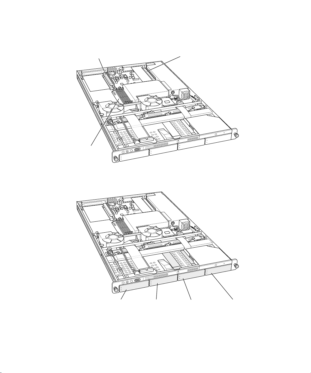
7 If necessary, install any optional internal components, such as additional memory or a PCI
card, in the server. Follow the appropriate instructions in Chapter 5, “Installing or Replacing
Server Components,” on page 49.
PCI card slots (2) PCI/AGP card slot
RAM slots (4)
8 If necessary, install any additional Apple Drive Modules in the front panel of the server.
Follow the instructions in “Installing or Replacing an Apple Drive Module” on page 50.
Drive module bay 1 Drive module bay 2 Drive module bay 3 Drive module bay 4
28 Chapter 3
Page 29

Note: When installing a drive module for the first time, remove the blank drive module and
save it for possible future use. This unit is necessary for appropriate cooling of the server in a
drive bay that has no drive module in it.
When you’ve installed optional items, you’re ready to connect the server to the rack. If you
have a four-post rack or cabinet, proceed to the next section, “Install the Server in a Four-Post
Rack or Cabinet” on page 29. If you have a two-post rack, go to “Install the Server in a TwoPost (Telco) Rack” on page 37.
Install the Server in a Four-Post Rack or Cabinet
A four-post rack can be open or enclosed in a cabinet. Examples of both racks are shown
below. You follow the same steps to attach the server to either of these racks. For a cabinet,
however, you may have to remove the door before installing the server.
Important Be sure to check the documentation for your rack for any specific mounting
instructions.
Four-post cabinet rack
Four-post open rack
Installing Your Server in a Rack 29
Page 30

Once you’ve marked the exact position for the server on the rack, you’re ready to attach the
server. Here is an overview of the procedure.
m Connect the cover of the server to the front of the rack.
m Assemble the rear mounting hardware.
m Connect the rear mounting hardware to the server enclosure.
m In a four-post rack, install the cable-management arm.
m Slide the server into the cover and secure it.
Follow these steps to attach the server to the rack.
1 Keep the cover of the enclosure level and support it from the center as you slide it into the
rack at the desired position.
Important Work with someone else to make sure the cover is supported and square to the
rack. The cover must be installed level to avoid changing its shape before the screws are
inserted to hold it in place.
Have someone support the
cover in the center while you
attach it to the rack.
30 Chapter 3
Page 31
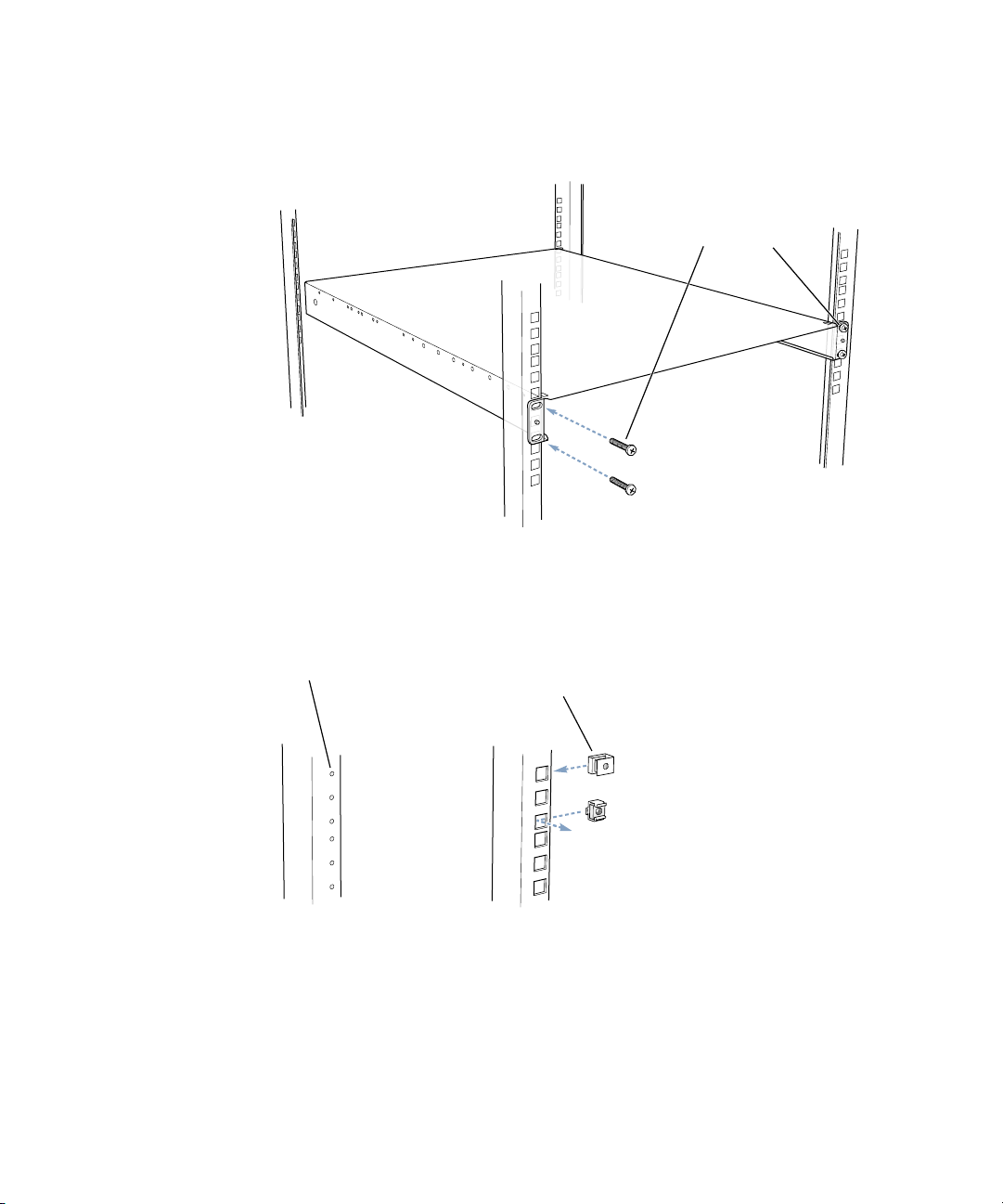
2 Screw the flanges at the front of the cover to the front rails of the rack
Be careful not to overtighten the flange screws. Doing so could change the shape of the
cover slightly and make it difficult to slide the server into the cover.
Attach the cover to the two
front rack mounting posts using
four of the screws provided.
Some racks have prethreaded holes and some have square holes that take clips with attached
nuts. You may need to insert a clip (not provided with the server) into the appropriate hole
before attaching the screw.
Some racks have
pre-threaded holes.
Other racks use various
types of removable,
captive nuts to secure
equipment.
Installing Your Server in a Rack 31
Page 32

3 At the back of the server, position the small bracket inside the server’s cover so that the head
T
of one rivet is facing the side of the cover.
Note: Start on the left side of the server (when facing the back). This makes installing the
cable-management arm more efficient.
4 Push the rivet head through the hole that’s near the back on the side of the cover.
Install the brackets on
the inside of the top cover.
he forward rivet on each bracket
must pass through the hole in the cover.
Each bracket must be
installed with the rivets
oriented low on the bracket.
The head of the rivet protrudes through the cover.
5 Position the long, U-shaped brace on the outside of the server’s cover, so that the curved end
is near the protruding rivet. The indented lip at the curved end of the brace should face the
rivet head.
6 Slide the lip at the end of the brace over both rivets on the small bracket and continue to
slide the brace forward a few inches.
Slide the brace
toward the front of the cover.
Make sure that both rivets
on the bracket have engaged
the slot in the brace.
Make sure the brace is on the outside of the cover and that both rivets are captured in the
center opening of the brace.
32 Chapter 3
Page 33
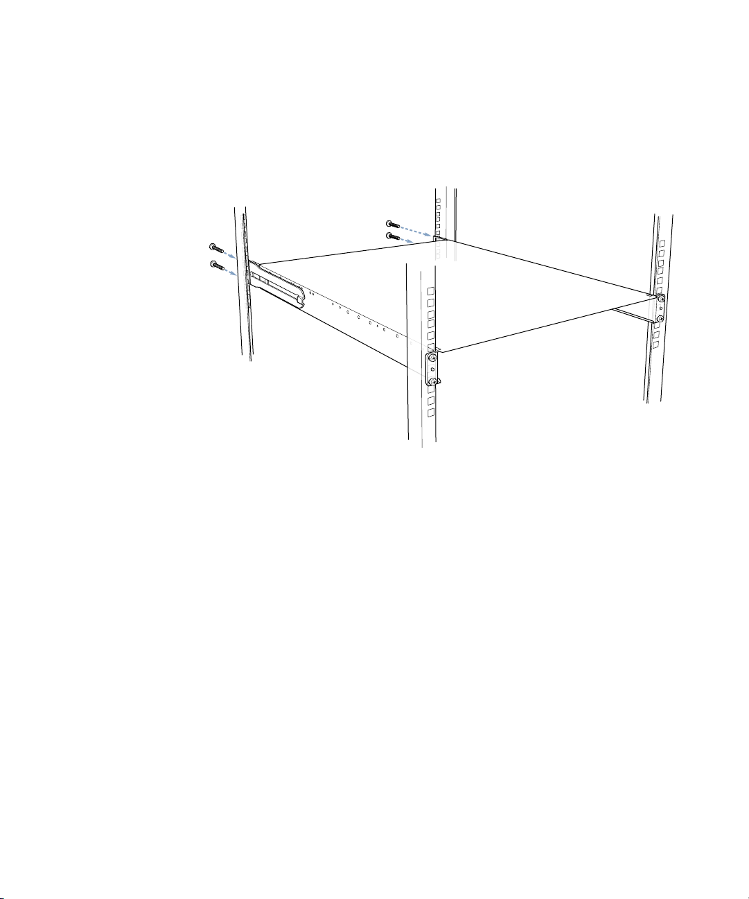
7 Slide the brace forward or backward so that the flat end of the brace is flush with the back
rail of the rack and screw the brace’s flange to the rail.
Note: If you are installing the cable-management arm and your server is the same depth as
your rack (or within an inch of it), only attach the brace to the rail on the left side of the
server (as you face the back panel). You attach the cable-management arm along with the
brace at the right rear of the server.
Attach the cover to the
two rear rack mounting
posts using four of the
screws provided.
8 Attach the second bracket and brace, as described in steps 3 through 7.
Note: If your rack is deeper than the server, the braces and brackets extend beyond the
server’s back panel to the rack’s rails.
Install the Cable-Management Arm
Xserve has a cable-management arm that allows you to open the server without
disconnecting cables. In addition, this device supports the cables and relieves strain on the
server’s back-panel connectors.
Important To open the server with the cables attached, you must install and use the cable-
management arm.
If your rack is the same depth as the server (or an inch or so deeper), you attach the cablemanagement arm to one rear post of the rack. If your rack is several inches deeper than the
server, you attach the cable-management arm to one of the braces that supports the back of
the server.
The steps that follow explain how to install the cable-management arm either to the rack or
to the brace.
Installing Your Server in a Rack 33
Page 34

Attach the Cable-Management Arm to the Rack
1 If the rear rails of your rack are flush with the server’s back panel or within an inch of it,
position the cable-management arm so that the short side is closer to the server’s back panel
and the holes on the long side align with the holes on the brace on the right side.
Place the cable-management arm over the
U-shaped brace, and secure both to the
rack with two of the screws provided.
2 Thread the hook-and-loop straps through the holes in the cable-management arm.
If the straps are already attached, skip this step.
3 Attach the long side of the folding arm to the rear rail, using two of the mounting screws
provided with the server.
The cable-management arm attaches on top of the right brace. The mounting screws hold
both in place.
See “Connect Cables to the Server” on page 40 for details on connecting cables and using the
cable-management arm.
Attach the Cable-Management Arm to the Support Brace
If the rear rails of your rack are more than an inch away from the server’s back panel, you
need to attach the cable-management arm to the support brace at the side of the server
(not to the rear rail). Otherwise the arm will not extend properly when you open the server
in the rack.
1 Use a very small Phillips screwdriver to disconnect the small clamp that wraps around the
long end of the cable-management arm (next to the two oval holes).
You’ll use this clamp and screw to attach the arm to the brace.
34 Chapter 3
Page 35

2 Hold the cable-management arm with the long end closer to you and fold the hinged section
of the long end away from you.
The hinged section is the part from which you removed the clamp and screw. This section
should be perpendicular to the main part of the arm, with the oval holes furthest from you.
Mount the cable-management arm as close to the back of
the server as possible. Rotate the mounting plate on the arm
so that it lies against the inside of the U-shaped bracket. The
U-shaped bracket should be sandwiched between the arm
and the small clamp. Secure the clamp with the screw that
held it stored on the arm.
ClampScrew
U-shaped bracketCable-management arm
3 Position the cable-management arm so that the hinged section is on the inside of the right
brace, about 2 inches behind the server’s back panel.
4 Hold the arm in place and put the clamp you detached on the opposite side of the arm, so
that the screw hole in the center shows through the open part of the brace.
5 Insert the screw into its hole and tighten it so that the arm is fastened to the brace.
6 Thread the hook-and-loop straps through the holes in the cable-management arm.
If the straps are already attached, skip this step.
See “Connect Cables to the Server” on page 40 for details on connecting cables and using the
cable-management arm.
Installing Your Server in a Rack 35
Page 36

Place the Server in the Rack
Once you’ve attached the cable-management arm, you can put the server into the rack.
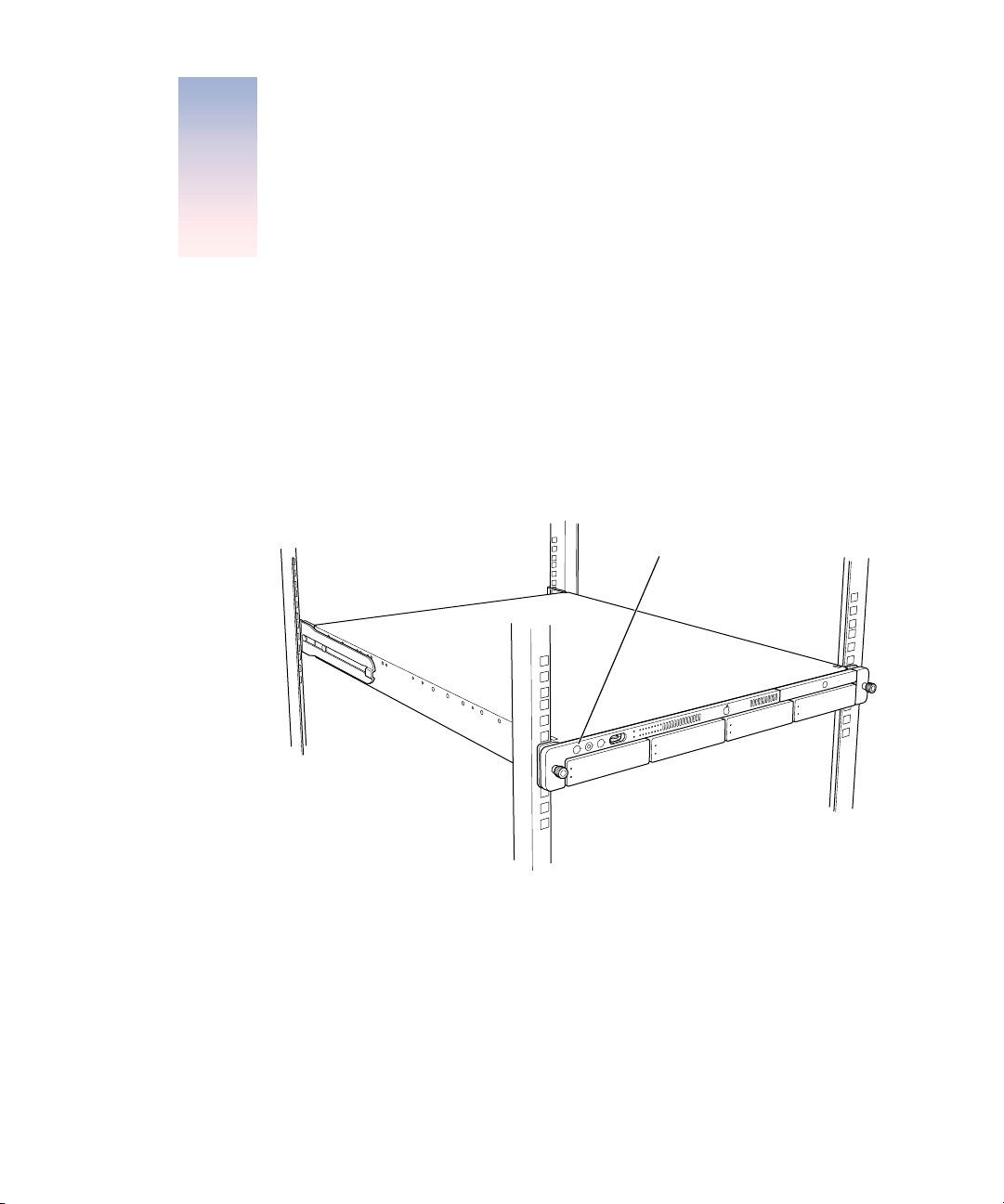
1 At the front of the rack, lift the server to the level where the enclosure’s cover is installed and
slide the server into the cover.
Insert the server into the cover
and slide it all the way back.
2 Secure the server in the rack by tightening the thumbscrews on the front.
Tighten the two thumbscrews
to secure the server in the rack.
To secure the drive modules in the
server, use the enclosure key to lock
them in place.
3 To further secure the server and prevent removal of the drive modules, use the enclosure key
(supplied with the server) to fasten the security lock on the front panel. (See the illustration
above.)
36 Chapter 3
Page 37

4 If you’ve installed the server in a cabinet, replace and close the cabinet door.
Once the server is secured in the rack or cabinet, you can attach cables for the server’s
connections.
See “Connect Cables to the Server” on page 40 for details of connecting cables and using the
cable-management arm.
Install the Server in a Two-Post (Telco) Rack
The server attaches to a two-post rack at the center of the enclosure, so that the front and
back of the server extend beyond the rack.
Important Before installing the server in a two-post rack, make certain that the rack is
securely fastened to the floor. Also check the rack’s documentation for any specific
installation instructions.
Follow these steps to install the server in a two-post rack. (These instructions assume that
you have previously taken the cover off the server; see “Prepare the Server for Installation”
on page 25 for details.)
Installing Your Server in a Rack 37
Page 38

1 Attach the small L-shaped brackets to the sides of the server enclosure’s cover with four of
the screws provided.
Attach the two telco mounting brackets to the server’s cover
using the four screws provided.
Orient the bracket so that the screws are at the top. Attach the brackets to holes that are
about one-third of the way back from the front panel.
2 Position the cover in the rack at the desired location and screw the flange of the L-shaped
bracket to the front of the rack on each side.
Important Be sure to work with another person for this part of the installation. The cover
should be held level to avoid changing its shape before the screws are inserted to hold it
in place.
Attach the cover to
the telco rack mounting
posts using four of the
screws provided.
Be careful not to overtighten the flange screws. Doing so could change the shape of the
cover slightly and make it difficult to slide the server into the cover.
38 Chapter 3
Page 39

3 Lift the server to the level where the cover is installed and slide the server into the cover.
Insert the server into the cover and slide it all the way back.
4 Secure the server in the rack by tightening the thumbscrews on the front.
Tighten the two thumbscrews
to secure the server in the rack.
To secure the drive modules in
the server, use the enclosure
key to lock them in place.
5 To further secure the server and prevent removal of the drive modules, use the enclosure key
(supplied with the server) to fasten the security lock on the server’s front panel. (See the
illustration above.)
Note: You cannot use the cable-management arm on an Xserve system that is installed in a
two-post rack.
Installing Your Server in a Rack 39
Page 40

Connect Cables to the Server
Once the server is secured in the rack, you can connect the cables and power cord to its back
and front panels.
Important If you use the cable-management arm, your cables must be approximately 3 feet
longer than the distance between the server and its peripheral devices. This extra length may
not be feasible for some cables, such as SCSI cables. In this instance, you can bypass the
cable-management arm with a shorter cable. But you must disconnect that cable when you
open the server.
Follow these steps to connect cables for network connections and peripheral devices.
1 Assemble the cables and devices you will connect to the server’s back panel. Make certain
that each cable has the proper connector and that it is designed for use in a high-capacity
server. (Check the documentation for each peripheral device or cable to determine that it
can be used with the server.)
2 Attach an identifying label to each cable you are connecting.
The labels allow you to locate a specific cable quickly and avoid errors when disconnecting
cables.
3 Beginning at one side of the server’s back panel, connect each cable to its respective port.
Do not attach the power cord yet.
FireWire ports (2)Power socket Gigabit Ethernet port
USB ports (2)
40 Chapter 3
VGA monitor portSerial console port
Page 41

4 Arrange all the cables on the back panel in the cable-management arm and secure them with
the straps provided with the cable-management arm.
The cable-management arm can only be used with a four-post rack or cabinet.
If you are not using the cable-management arm, skip this procedure. It’s a good idea to
group the cables and arrange them so that they don’t cause any hazard and are easy to
handle should you need to detach them when opening the server.
Gather all the cables attached to the server
except the power cord, and attach them to
the cable-management arm. Use the
hook-and-loop fastener straps
to secure the cables to
the arm.
Make sure you lay the cables against
the full length of the cable-management
arm to assure unobstructed extension.
a Group the cables together loosely and “fold” them to the right side of the back panel,
until they are near the short (inner) end of the cable-management arm.
b Reverse the direction of the cables and lay them along the edge of the cable-management
arm closest to the server’s back panel.
c Attach the cables to the arm with the straps provided.
Wrap the cables so that the sides of facing straps do not stick to each other.
d Reverse the direction of the cables again and lay them along the edge of the cable-
management arm furthest from the back panel.
e Attach the cables to the arm with the straps provided.
5 Connect the power cord to the back panel.
Installing Your Server in a Rack 41
Page 42

6 Attach the power cord’s retainer clip to the back panel to keep the power cord in place when
you open the server.
The ends of the clip fit into the small openings at either side of the power socket. Be sure
that the rounded part of the clip goes under the cord, so that the cord is supported.
Attach the power cord
retainer clip to the two
loops on the back of
the server. Snap the
cord into the clip so that
it cradles the cord.
If more than one power cord came with your server, use the appropriate cord for the
electrical service available at your location.
You can use the long power cord supplied with the server, or another cord, such as one
already installed in the rack.
7 If you will be using the FireWire port on the front panel of the server, connect a cable to it.
8 When all cables are in place, connect each one to its intended device.
Important When connecting peripheral devices, be sure to allow adequate space at the
front and back of the server for proper airflow and access to the rack for servicing.
42 Chapter 3
Page 43

9 After all connections are complete, plug the power cord into a power source.
Warning This equipment is intended to be electrically grounded. Your server is
equipped with a three-wire grounding plug—a plug that has a third (grounding) pin.
This plug will fit only a grounded AC outlet. This is a safety feature. If you are unable
to insert the plug into the outlet because the outlet is not grounded, contact a licensed
electrician to replace the outlet with a properly grounded outlet. Do not defeat the
purpose of the grounding plug!
Because you are installing the server in a rack with other equipment, be certain that the
power outlet and any other equipment, such as a power strip, used with the rack is
designed to carry the electrical load of multiple devices. Check the documentation for
your rack for any special instructions.
With the server in the rack and the cables in place, you can prepare to set up the Mac OS X
Server software.
Preparing the Server for Software Setup
When the server is installed and secured, you are ready to set up the software.
You can configure the server locally or use the remote setup tools. If you want to configure
the server software where the server and rack are located, you can do one of the following:
m Connect a monitor, keyboard, and mouse to the server.
You can connect the monitor to the VGA port and connect the keyboard and mouse to the
USB ports on the server’s back panel. If a KVM (keyboard-video-mouse) switch is installed in
the rack, you can use it. See the documentation for the KVM switch for instructions.
m Connect a computer running Mac OS X to the server using an Ethernet connection on the
same subnet as the server.
If you want to set up the software from another location, you can work at a computer on the
server’s network, using the remote server administration software and command-line tools.
You need to install the administration software on the portable or network computer before
you can set up the software.
See Chapter 4, “Using Your Server,” on page 45 for more about software configuration.
Installing Your Server in a Rack 43
Page 44

Page 45
CHAPTER
4
4 Using Your Server
When you’ve connected the cables and peripheral devices you plan to use with your server,
you can turn it on and set up the software and network services.
Starting Up the Server
Press the power button at the left side of the server’s front panel to turn it on.
Power button
The power indicator light turns on, and the server starts up. Status lights on the front panel
indicate network connection, system activity, and drive module use.
Detailed instructions for setting up all the services and options of the Mac OS X Server
software are provided in the software documentation included with the server. See the
Quick Start for Xserve booklet for a roadmap to the software documentation.
45
Page 46

Monitoring Status Lights and Other Indicators on the Server
The server has a number of built-in sensors that detect and report essential operating factors,
such as power, temperature, and condition of several key components. You can monitor the
server’s operation using the lights on the unit or using the remote monitoring tools.
The server’s status lights are listed in the table below.
Indicator Color Description
Power White On and OK
Security lock Yellow Lock is engaged
System identifier Yellow Indicates that there is a hardware error in the server
or that someone has turned on the light manually;
check the server monitoring application for more
information.
Ethernet
(lower is built-in port;
upper is network card,
if installed)
System activity Blue Two rows of eight LEDs; in server with one processor,
Drive module
(upper LED)
Drive module
(lower LED)
Green
No light
Green
Yellow
Red
No light
Blinking blue
Link
No connection
rows of lights work in tandem; in dual-processor
server, rows operate independently for each
processor
Powered and running
Warning condition
Problem or failure
Drive module can be removed
Disk activity; do not remove drive module
If the Server Has a Problem
If you discover a problem with the server, you can assess the situation and often solve the
problem from a remote computer. The Mac OS X Server software documentation contains
information about restarting the server and solving some other problems; see the Quick
Start for Xserve booklet to learn which parts of the software documentation to consult.
46 Chapter 4
Page 47

If you have access to the server itself, you can use the buttons on the front panel to change
the server’s status. These buttons include
m Power: Press to turn the server on.
m System identifier: This light helps you determine which server in a multiple-server rack
has a problem. The light turns on when the server has a problem; it can also be turned on
manually. Pressing the button next to this light turns the light off when it’s on. (Duplicates
of the button and light are on the back panel.)
Should you need to open the server and exchange components, see Chapter 5, “Installing or
Replacing Server Components,” on page 49 for instructions. If you want to exchange or add a
drive module, see “Installing or Replacing an Apple Drive Module” on page 50.
What to Do If . . .
If you detect trouble with the server, follow the guidelines below to solve the problem.
Problem Try this
Server doesn’t start up Start up from the system CD that came with your server.
1. With the power off, hold in the system identifier button and
press the power button.
2. Continue holding in the system identifier button until the light
next to this button begins to flash and the CD tray opens (about
5 seconds).
3. Release the system identifier button and put the system CD in
the open tray.
4. Close the CD tray.
Hard disk is erased or server
software is damaged
Reinstall system software from the system CD. (Start up from the
CD and use the Installer to reinstall the software.).
If you can’t solve the problem on your own, go to the Help for Mac OS X Server. Check the
“News” section of Help for the latest information on server hardware.
Also go to the Apple Support Web site for the latest troubleshooting information and
software updates:
www.apple.com/support
Using Your Server 47
Page 48

Page 49

CHAPTER
5
5 Installing or Replacing Server
Components
Your server is designed so that you can install or exchange drive modules while the server is
operating. The server should be turned off before opening it to install or exchange other key
components.
When working with the server hardware, always guard against static electricity, which can
damage electronic components. Touch a metal surface before handling RAM or an expansion
card or working inside the server.
49
Page 50

When installing components, it’s wise to wear a wrist grounding strap that prevents static
electricity from discharging into electronic components.
It is good practice to use
an antistatic wrist strap
when accessing the
interior of the server.
You can also arrange for an Apple-authorized service provider to install or replace
components in the server. For details about this service, see the support information that
came with your server. Additional support information is available at the Apple Support Web
site: www.apple.com/support
Installing or Replacing an Apple Drive Module
The drive modules in the server are hot-pluggable; that is, you can remove one and replace it
with another drive while the server is running. A status light on each drive indicates when it’s
safe to remove a drive without losing any information.
Follow these steps to install or replace a drive module.
1 If necessary, use the enclosure key to unlock the security lock on the server’s front panel.
50 Chapter 5
Page 51

2 Remove the blank drive module or the drive currently installed.
m If there is no drive installed, press the handle on the front of the blank drive module so
that the handle pops out, then pull the blank drive module out of the front panel.
Remove the blank
drive module from the bay.
m If there is a drive module already in the bay:
a Make sure the drive currently in the bay is not being used by any application and that
the drive is not being shared by the server. (See the Mac OS X Server documentation
for information about shared drives.)
b Press the handle on the front of the drive module so that the handle pops out.
When pressed, the drive
module handle pops out.
Installing or Replacing Server Components 51
Page 52

c Wait for the upper disk light to go off, then grasp the handle and pull the drive module
out of its bay and set it aside.
Pull the server drive
module out of the server.
3 Press to open the handle of the replacement drive module and slide it into the empty bay
until its connector clicks into place.
4 The disk status light turns green to indicate normal operation.
Important Be sure to save the blank drive module if you removed one. This module should
always be placed in an empty drive bay to maintain proper airflow through the server.
Opening and Closing the Server
1 Shut down the server.
Be sure to wait a brief period to allow the server’s internal components to cool.
Warning Always shut down your server before opening it to avoid damaging its internal
components or the components you want to install. Do not open the server or attempt to
install items inside it while it is turned on. After shutting down your server, the internal
components can be very hot. Let the computer cool down before continuing.
2 If the cable-management arm is not in use for all cables, unplug all cables from the back panel
except the power cord. (If necessary, also remove the FireWire cable from the front panel.)
52 Chapter 5
Page 53

3 Touch the metal enclosure to discharge any static electricity.
Important Always do this before you touch any parts, or install any components, inside
the computer. To avoid generating static electricity, do not walk around the room until you
have finished installing the expansion card, memory, or internal storage device and have
closed the computer.
4 Unplug the power cord.
Warning The power supply in your computer is a high-voltage component and should
not be opened for any reason, even when the computer is off. If the power supply needs
service, contact your Apple-authorized dealer or service provider.
5 Loosen the thumbscrews at the front of the server’s cover.
Unscrew the two
thumbscrews to
release the server.
Installing or Replacing Server Components 53
Page 54

6 Grasp the thumbscrews and use them to slide the server forward.
Pull the server out of
the rack until it stops.
The server’s cover remains in place. The enclosure and components slide forward until the
interior is in view.
54 Chapter 5
Page 55

If you need to remove the server from the rack, press the release latches on each side of the
server’s interior, then carefully slide it forward and lift it out of the cover.
Press these two
latches to release
the server from
the cover.
7 When you’ve completed your work inside the server, carefully slide it closed and tighten the
front thumbscrews to secure it in the rack.
Installing or Replacing Server Components 55
Page 56

Adding Memory
The server has four memory slots, at least one of which is filled at the factory. Follow these
steps to add memory to the server.
You can install additional dynamic random-access memory (DRAM) in packages called
Dual Inline Memory Modules (DIMMs) in the four DRAM DIMM slots on the server’s main
logic board. You can expand your computer’s DRAM to a maximum of 2 gigabytes (GB). To
check the amounts of DRAM installed, use the Apple System Profiler (located in the Utilities
folder, in your computer’s Applications folder).
DIMMs must fit these specifications:
m PC2100 double-data-rate (DDR) Synchronous DRAM (SDRAM); also described as DDR-266
m 2.5 volt (V)
m 64-bit wide, 184-pin module
m Maximum number of memory devices on a DIMM is 16.
m Unbuffered; do not use registered or buffered DRAM.
m Height must not exceed 1.25 inches.
Important DIMMs from older Macintosh computers are not compatible with your server.
Do not use older DIMMs even if they fit into the DIMM slots.
Note: When purchasing DRAM for use in the server, make sure that the memory conforms
to the JEDEC specification. Check with your memory vendor to ensure that the DRAM DIMM
supports the correct timing modes and that the Serial Presence Detect (SPD) feature has
been programmed properly, as described in the JEDEC specification. You can purchase
memory where you bought your server.
Follow these steps to install memory in the server.
1 Shut down the server.
Be sure to alert users of the server that it will be unavailable for a period of time.
2 Unplug the power cord from the back panel of the server. (If the cable-management arm is
not attached, you also need to disconnect cables from the back panel.)
Warning The only way to disconnect power completely is to unplug the power cord.
Make sure that the cord is disconnected before removing or installing any components
inside the server.
56 Chapter 5
Page 57

3 Open the server to its full length.
See “Opening and Closing the Server” on page 52 for details.
You can also remove the server from the rack (leaving the cover in place) and do the
installation with the server on a sturdy flat surface.
4 Locate the RAM slots at the rear center of the server.
RAM slots (4)
5 Open the ejectors on the DIMM slots you want to use by pushing down on them.
Installing or Replacing Server Components 57
Page 58

6 Align the DIMM in the slot as pictured and push the DIMM down until the ejectors snap
T
T
into place.
Important Do not touch the DIMM’s connectors. Handle the DIMM only by the edges.
DRAM DIMM (Your DIMM’s shape and components may vary.)
he DRAM DIMM is designed to fit into
the slot only one way. Be sure to align the
notch in the DIMM with the small rib
inside the slot. With the ejectors in the
open position (as shown), push down
on the DIMM until it snaps into place.
he ejectors will automatically close.
Ejectors
(They should be pushed outward and down
to be in the open position, as shown.)
Connectors Notch DRAM slot (1 of 4)
Rib (inside slot)
7 Close the server and tighten its thumbscrews.
8 Reconnect the power cord and any cables that you removed.
58 Chapter 5
Page 59

Installing a PCI Card
You can add to the capabilities of your server by installing cards in its expansion slots. The
computer has three expansion slots, which accommodate Peripheral Component Interconnect
(PCI) cards. In some models, the slot that takes a short (7-inch) PCI card can accept a 4x
Accelerated Graphics Port (AGP) card.
About PCI Cards for the Server
Two of the server’s slots accept PCI cards up to 12 inches long; the third slot accepts a 7-inch
card. (Some models come with a card installed in one or two slots.) Install only expansion
cards that are compatible with Mac OS X and that comply with the PCI 2.1 standard.
PCI Card Requirements
Criteria for PCI cards you can install in the Xserve server are summarized in the table below.
12-inch PCI card 7-inch PCI card
64-bit or 32-bit data width 32-bit data width
66 or 33 MHz frequency
(If a 33 MHz card is used in one slot, both cards
operate at 33 MHz.)
3.3 volt (V) 3.3 V
12 or 7 inches long 7 inches long
Important The PCI card must have a 3.3 V connector or a universal connector to fit into the
66 MHz frequency
4x AGP card with an AGP adapter
server’s expansion slots. Cards with a 5 V connector will not work in this server.
Power Consumption of Cards
Maximum power consumption for all three expansion slots combined should not exceed 50
watts (W). Check the documentation that came with each card to be certain that the cards
don’t exceed this power consumption.
Installing or Replacing Server Components 59
Page 60

Install a PCI Card in a Long Card Slot
Follow these steps to install a PCI card in one of the long PCI slots.
1 Shut down the server.
Be sure to alert users of the server that it will be unavailable for a period of time.
2 Unplug the power cord from the back panel of the server. (If the cable-management arm is
not attached, you will also have to disconnect cables from the back panel.)
Warning The only way to disconnect power completely is to unplug the power cord.
Make sure that the cord is disconnected before removing or installing any components
inside the server.
3 Loosen the thumbscrew on the back panel for the PCI slot that you want to use and swivel
open the small metal piece that holds the thumbscrew.
Also grasp the slot cover and remove it through the slot opening, if possible.
You can skip this step if there is already a card in the slot you want to use.
Loosen the thumbscrew and
swing the small metal plate
to its open position.
4 Move to the front of the server and open it to its full length.
See “Opening and Closing the Server” on page 52 for details.
You can also remove the server from the rack (leaving the cover in place) and do the
installation with the server on a sturdy flat surface.
60 Chapter 5
Page 61

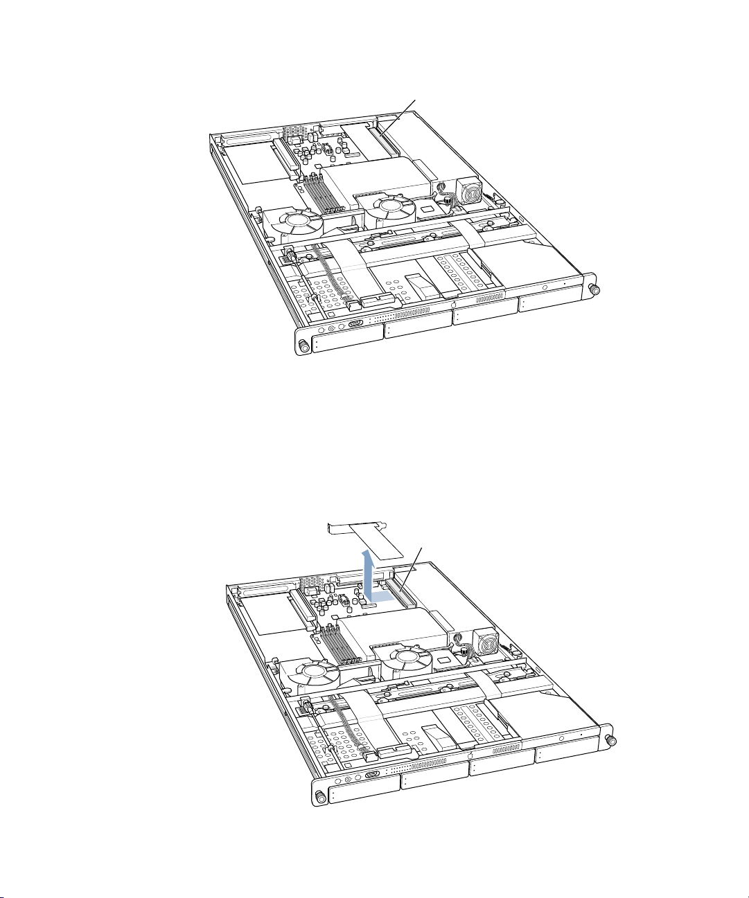
5 Locate the long PCI slots at the back left side of the server.
You can install a card in one or both slots. Cards are oriented horizontally in the server. The
long PCI cards fit into an assembly unit that contains the sockets for both cards.
PCI card slots (2)
6 Grasp the PCI card assembly, which may contain one or two cards, gently pull it toward the
left side of the server’s enclosure, and then lift it out of the server.
Pull the PCI card assembly to the side
to disengage it from the connector, and
then pull it up and out of the server.
Set the card assembly on a cushioned surface.
Installing or Replacing Server Components 61
Page 62

7 Prepare the card slot by doing one of the following:
m If a card is already in the slot you want to use, hold the assembly and remove the card,
taking care not to touch its surface.
Store the card in static-proof packaging made to protect it.
m If no card is in the slot, be sure to remove the slot cover (which came loose when you
loosened the cover’s thumbscrew on the back panel).
8 Remove the card you’re installing from its packaging and hold it by its corners, taking care
not to touch the gold connector or any of the components on the card.
9 Align the card’s connector with the expansion slot in the assembly and carefully press it into
the slot until the connector is inserted all the way into the slot.
PCI card
PCI riser card
If you are installing a 12-inch card, align it with the card guide.
Press the card gently but firmly until the connector is fully inserted.
m Don’t rock the card from side to side; instead, press the card straight into the slot.
m Don’t force the card. If you meet a lot of resistance, pull the card out. Check the
connector and the slot for damage or obstruction, then try inserting the card again.
m Pull the card gently to see if it is properly connected. If it resists and stays in place, and if
its gold connectors are barely visible, the card is connected.
62 Chapter 5
Page 63

10 Replace the card assembly by aligning it with the connector and pressing it into place.
A
ttach the PCI card assembly to the connector on the logic board by pushing
it in sideways. Be sure to engage the card in this slot on the back panel.
If the PCI card you are installing is full-length (12 inches), make sure
it fits in one of these two card guides. The card guides snap forward
and backward a short distance to help you position them on the cards.
11 Close the card retainer on the back panel and tighten its thumbscrew.
Swing the small metal plate
to its closed position, and
tighten the thumbscrew.
Warning If you removed a card from the server and did not install a replacement, be
sure to place a port access cover over the empty slot in the back panel. Do not leave an
empty slot without a cover. An uncovered slot can affect the air flow that cools the
server’s internal components and cause damage.
12 Close the server and reconnect any cords or cables that you detached.
Installing or Replacing Server Components 63
Page 64

Install a PCI Card in the PCI/AGP Card Slot
You can install a 7-inch PCI card in the PCI/AGP card slot.
Note: An AGP card requires a special adapter.
Follow these steps to install a PCI card in the PCI/AGP slot.
1 Shut down the server.
Be sure to alert users of the server that it will be unavailable for a period of time.
2 Unplug the power cord from the back panel of the server. (If the cable-management arm is
not attached, you will also have to disconnect cables from the back panel.)
Warning The only way to disconnect power completely is to unplug the power cord.
Make sure that the cord is disconnected before removing or installing any components
inside the server.
3 Loosen the thumbscrew on the back panel for the PCI/AGP slot and swivel open the small
metal piece that holds the thumbscrew.
If there is no card already in the slot, also grasp the slot cover and remove it through the slot
opening, if possible.
You can skip this step if there is already a card in the slot.
Loosen the thumbscrew and
swing the small metal plate
to its open position.
4 Move to the front of the server and open it to its full length.
See “Opening and Closing the Server” on page 52 for details.
You can also remove the server from the rack (leaving the cover in place) and do the
installation with the server on a sturdy flat surface.
64 Chapter 5
Page 65
5 Locate the PCI/AGP slot at the back right side of the server.
PCI/AGP combo card slot
6 Prepare the card slot by doing one of the following:
m If a card is already in the slot, remove it by grasping the edges and gently pulling it toward
the left side of the enclosure.
Store the card in static-proof packaging made to protect it.
m If no card is in the slot, be sure to remove the slot cover (which came loose when you
loosened the cover’s thumbscrew on the back panel).
Pull the PCI/AGP card to the side to
disengage it from the connector, and
then pull it up and out of the server.
Installing or Replacing Server Components 65
Page 66

7 Remove the card you’re installing from its packaging and hold it by its corners, taking care
not to touch the gold connector or any of the components on the card.
8 Align the card’s connector with the expansion slot and carefully press it to the right until the
connector is inserted all the way into the slot.
Attach the PCI/AGP card to the connector by pushing it in sideways.
Be sure to engage the card in this slot on the back panel.
Press the card gently but firmly until the connector is fully inserted.
m Don’t rock the card from side to side; instead, press the card straight into the slot.
m Don’t force the card. If you meet a lot of resistance, pull the card out. Check the
connector and the slot for damage or obstruction, then try inserting the card again.
m Pull the card gently to see if it is properly connected. If it resists and stays in place, and if
its gold connectors are barely visible, the card is connected.
66 Chapter 5
Page 67

9 Close the card retainer on the back panel and tighten its thumbscrew.
Swing the small metal plate
to its closed position, and
tighten the thumbscrew.
Warning If you removed a card from the server and did not install a replacement, be
sure to place a port access cover over the empty slot in the back panel. Do not leave an
empty slot without a cover. An uncovered slot can affect the air flow that cools the
server’s internal components and cause damage.
10 Close the server and reconnect any cords or cables that you detached.
Replacing the Battery
The server has a 3.6 V lithium battery installed on the main logic board. Some signs that you
need to replace the battery are intermittent problems starting up the computer and random
changes in its date and time settings. You can purchase a replacement battery from the
dealer where you bought your server.
Warning There is a risk of explosion if the incorrect type of battery is installed.
1 Shut down the server.
Be sure to alert users of the server that it will be unavailable for a period of time.
2 Unplug the power cord from the back panel of the server. (If the cable-management arm is
not attached, you will also have to disconnect cables from the back panel.)
Warning The only way to disconnect power completely is to unplug the power cord.
Make sure that the cord is disconnected before removing or installing any components
inside the server.
Installing or Replacing Server Components 67
Page 68

3 Open the server to its full length.
See “Opening and Closing the Server” on page 52 for details.
You can also remove the server from the rack (leaving the cover in place) and do the
installation with the server on a sturdy flat surface.
4 Locate the battery holder near the back of the server.
Remove the battery by pulling it up and out of
its holder. You may need to spread these two tabs
slightly apart to release the battery. Spread the
tabs gently so they don’t break. Positive and
negative symbols are molded inside the holder
to help you orient the battery correctly.
5 Remove the battery from its holder, noting the orientation of the battery’s positive end.
(A plus sign is marked on the holder.)
6 Insert the new battery in the holder, making sure the battery’s positive end aligns with the
positive symbol on the holder.
7 Close the server and tighten the thumbscrews to secure it.
8 Reconnect any cords or cables that you disconnected.
Important Batteries contain chemicals, some of which may be harmful to the environment.
Please dispose of used batteries according to your local environmental laws and guidelines.
68 Chapter 5
Page 69

APPENDIX
A
A Specifications
Processor and Memory Specifications
Processor
m PowerPC G4 (single or dual), 1 GHz processor speed (at a minimum)
m 256K level 2 cache
m 2 MB backside DDR L3 cache
Random-access memory (RAM)
m Minimum of 256 MB of DDR RAM, maximum of 2 GB of RAM in four DIMM slots
m PC2100 double-data-rate (DDR) Synchronous DRAM (SDRAM); also described as DDR-266
m 2.5 volt (V) unbuffered, unregistered, 64-bit wide, 184-pin module
m 256 or 512 MB DIMMs; maximum number of memory devices on a DIMM is 16.
m Height must not exceed 1.25 inches.
Dimensions and Operating Environment
Dimensions
m Height: 1.75 in. (4.4 cm) (1U)
m Width: 19.0 in. (48.3 cm)
m Depth: 29.5 in. (74.9 cm)
m Weight (with one drive module): 26.6 lbs. (12.0 kg)
m Drive module weight: 2 lbs. (0.9 kg)
Weight depends on the number of drive modules installed in the server.
Operating environment
m Operating temperature: 10° to 35° C (50° to 95° F)
m Storage temperature: –40° to 47° C (–40° to 116.6° F)
m Relative humidity: 5% to 95% (noncondensing)
m Altitude: 0 to 3048 meters (0 to 10,000 feet)
69
Page 70

CD-ROM Specifications
m Disk dimensions supported: 12 cm (4.7 in.)
Ethernet Specifications
m IEEE 802.3 compliant
m Maximum cable length: 100 meters (m)
m Connectors: RJ-45 for 10Base-T, 100Base-TX, and 1000Base-T
m Media, 10Base-T: Category 3 or higher UTP on 2 pairs up to 100 m
m Media, 100Base-TX: Category 5 UTP on 2 pairs up to 100 m
m Media, 1000Base-T: Category 5 and 6 UTP on 4 pairs up to 100 m
m Channel speeds: IEEE Auto Negotiation of 10Base-T, 100Base-TX, and 1000Base-T
FireWire Specifications
m Data transfer speed: 100, 200, and 400 megabits per second
USB Specifications
m Support for USB 1.1
m Two external Universal Serial Bus (USB) Type A ports
m Each port is on a separate 12 megabit per second (Mbps) USB channel.
m 500 milliamperes (mA) at 5 V are available per port for a total of 1 ampere (A).
70 Appendix A
Page 71

Serial Port Specifications
m 9-pin D connector
1234
5
6789
m Pin signals
1: Received line signal detector (RLSD)
2: Received data (RD)
3: Transmitted data (TD)
4: DTE ready (DRT CD)
5: Signal ground (SGND)
6: DCE ready (DCR CC)
7: Request to send (RTS)
8: Clear to send (CTS)
9: Ring indicator (RI)
Video Card Specifications
m Standard VGA connection
m 32 MB of video memory
m Support for 33 and 66 MHz operation
m Support for startup without a monitor connected
Power Supply
AC line input
m Line voltage/current: 100–240 V alternating current (AC), 6 A maximum, single phase,
set automatically
m Frequency: 50–60 hertz (Hz)
Specifications 71
Page 72

Power Requirements for Devices You Can Connect
Expansion cards
m Maximum power consumption by three PCI cards combined is 50 W (total for two 12-inch
cards and one 7-inch card).
m 12-inch PCI card slots
m Data width: 32 or 64 bits
m Frequency: 33 or 66 MHz
m Power: 3.3 V
m Length: 7 or 12 in.
m PCI/AGP card slot (AGP card requires adapter)
m Data width: 32 bits
m Frequency: 66 MHz
m Power: 3.3 V
m Length: 7 inches
FireWire devices
m The computer can provide up to 15 W total to all FireWire ports combined.
m Output voltage range: Approximately 13 to 30 V
m Output power range: Up to 15 W
USB devices
m Each of the computer’s built-in USB ports is allotted 500 mA.
System Clock and Battery
CMOS custom circuitry with long-life lithium battery. You can replace the computer’s battery
(see “Replacing the Battery” on page 67) with a new one purchased from an Appleauthorized dealer.
72 Appendix A
Page 73

APPENDIX
B
B Safety, Maintenance, and Ergonomics
Important Safety Information
For your own safety and that of your equipment, always take the following precautions.
Important The only way to disconnect power completely is to unplug the power cord.
Make sure at least one end of the power cord is within easy reach so that you can unplug the
server when you need to.
Disconnect the power plug (by pulling the plug, not the cord) if any of the following
conditions exists:
m you want to remove any parts (leave the cord disconnected as long as the cover is off )
m the power cord or plug becomes frayed or otherwise damaged
m you spill something into the case
m your server is exposed to rain or any other excess moisture
m your server has been dropped or the case has been otherwise damaged
m you suspect that your server needs service or repair
m you want to clean the case (use only the recommended procedure described later)
Be sure that you always do the following:
m Keep your server away from sources of liquids, such as washbasins, bathtubs, shower
stalls, and so on.
m Protect your server from dampness or wet weather, such as rain, snow, and so on.
m Read all the installation instructions carefully before you plug your server into a wall
socket or power strip.
m Keep these instructions handy for reference by you and others.
m Follow all instructions and warnings dealing with your system.
Electrical equipment may be hazardous if misused. Operation of this product, or similar
products, must always be supervised by an adult. Do not allow children access to the interior
of any electrical product and do not permit them to handle any cables.
73
Page 74

Handling Your Computer Equipment
Follow these guidelines for handling your computer and its components:
m When the server is removed from its rack, set it on a sturdy, flat surface.
Important Do not put a monitor or any other device on top of the server. Essential
components are installed in this low-profile server, and any weight on top of the case could
damage these components.
m When connecting or disconnecting a cable, always hold the cable by its connector (the
plug, not the cord).
m Turn off your server before connecting or disconnecting a cable for a monitor or a serial
device. Failure to do so could damage your equipment or cause an interruption in the
server’s operation.
Certain components and cables—hard disks, a VGA monitor, FireWire, Ethernet, and USB
devices—are designed to be installed or removed while the server is turned on and
operating.
m Never force a connector into a port. If the connector and port do not join with reasonable
ease, they probably don’t match. Make sure that the connector matches the port and that
you have positioned the connector correctly in relation to the port.
m Take care not to spill any food or liquid on the server or other components. If you do,
turn your server off immediately and unplug it before cleaning up the spill. Depending on
what you spilled and how much of it got into your equipment, you may have to arrange
for an Apple-authorized service provider to inspect or repair the server.
m Protect the server and its components from direct sunlight and rain or other moisture.
m Keep all ventilation openings clear and unobstructed. Without proper air circulation,
components can overheat, causing damage or unreliable operation.
74 Appendix B
Page 75

Protecting Your CD Drive
To keep your CD drive working properly:
m Position your server so that when the tray opens, it doesn’t bump into anything.
m Do not leave the disc tray open. If dust gets on the lens of the CD-ROM drive, the drive
may have problems reading your discs.
m Do not put anything (for instance, a cup) on top of the tray when it is open.
m Do not force the tray open by hand. In an emergency, you can use an opened paper clip
in the tiny hole near the drive to eject a disc.
m Do not wipe the lens with a paper towel or other abrasive surface. If you need to clean
the lens, see an Apple-authorized service provider for a lens cleaner.
You may want to open the tray and take out your disc before shutting down.
Power Supply
The power supply in your computer is a high-voltage component and should not be opened
for any reason, even when the computer is off. If the power supply needs service, contact
your Apple-authorized dealer or service provider.
Cleaning Your Equipment
Follow these general rules when cleaning the outside of your server:
m Use a damp, soft, lint-free cloth to clean the computer’s exterior. Avoid getting moisture
in any openings.
m Don’t use aerosol sprays, solvents, or abrasives.
Cleaning the Server’s Case
To clean the case, do the following:
1 Turn off the computer completely and then disconnect the power plug. (Pull the plug, not
the cord.)
2 Wipe the surfaces lightly with a clean, soft cloth dampened with water.
Safety, Maintenance, and Ergonomics 75
Page 76

Apple and the Environment
At Apple, we recognize our responsibility to minimize the environmental impacts of our
operations and products.
For More Information
Go to www.apple.com/about/environment
Health-Related Information About Computer Use
In most instances, you will probably set up and administer your server from a remote
location, such as a computer on the server’s network. If you work at the server rack for
extended periods, be sure to following these guidelines for avoiding muscle soreness, eye
fatigue, or other discomforts associated with computer use.
m If feasible in the server location, use an adjustable chair that provides firm, comfortable
support. The back of the chair should support your lower back (lumbar region). Follow
the manufacturer’s instructions for adjusting the backrest to fit your body properly.
m When using a keyboard at the server location, your shoulders should be relaxed. Your
upper arm and forearm should form an approximate right angle, with your wrist and hand
in roughly a straight line. Depending on the location of the monitor and keyboard
connected to the server, you may have to adjust the height of your chair so that you can
maintain a comfortable position. Your feet should be flat on the floor or on a footrest.
76 Appendix B
Page 77

Communications Regulation Information
FCC Statement
This equipment has been tested and found to comply with the limits for a Class A digital device, pursuant to Part
15 of FCC rules. These limits are designed to provide reasonable protection against harmful interference when
the equipment is operated in a commercial environment. This equipment generates, uses, and can radiate radiofrequency energy, and if not installed and used in accordance with Apple’s instructions, may cause harmful
interference with radio communications. Operation of this equipment in a residential area is likely to cause
harmful interference, in which case the user will be required to correct the interference at his or her own
expense.
Important Changes or modifications to this product not authorized by Apple Computer, Inc., could void the
EMC compliance and negate your authority to operate the product.
This product was tested for EMC compliance under conditions that included the use of Apple peripheral devices
and Apple shielded cables and connectors between system components. It is important that you use Apple
peripheral devices and shielded cables and connectors between system components to reduce the possibility of
causing interference to radios, television sets, and other electronic devices. You can obtain Apple peripheral
devices and the proper shielded cables and connectors through an Apple-authorized dealer. For non-Apple
peripheral devices, contact the manufacturer or dealer for assistance.
The above model is certified only as a component for use with other equipment, where the suitability of the
combination is to be determined by a Nationally Recognized Testing Laboratory.
Industry Canada Statement
Complies with the Canadian ICES-003 Class A specifications.
Cet appareil numérique de la classe A est conforme à la norme NMB-003 du Canada.
European Union Statement
Complies with European Directive 89/336/EEC.
CISPR 22 & EN55022 Statement
Warning
This is a Class A product. In a domestic environment this product may cause radio interference, in
which case the user may be required to take adequate measures.
VCCI Class A Statement
Laser Information
If you have an internal Apple CD-ROM drive in your computer, your computer is a Class 1 laser product. The Class
1 label, located in a user-accessible area, indicates that the drive meets minimum safety requirements. A service
warning label is located in a service-accessible area. The labels on your product may differ slightly from the ones
shown here.
Class 1 label
Service warning label
77
Page 78

High-Risk Activities Warning
This computer system is not intended for use in the operation of nuclear facilities, aircraft navigation or
communications systems, or air traffic control machines, or for any other uses where the failure of the computer
system could lead to death, personal injury or severe environmental damage.
78
 Loading...