

Page 1
Service Source
Xserve (Late 2006)
Xserve (Late 2006), Xserve (Early 2008)
Updated: 23 December 2008
© 2006, 2007, 2008 Apple Inc. All rights reserved.
Page 2

Apple Inc.
© 2007, 2008 Apple Inc. All rights reserved.
Under the copyright laws, this document may not be copied, in whole or in part, without the
written consent of Apple.
Every eort has been made to ensure that the information in this document is accurate. Apple is
not responsible for printing or clerical errors.
Apple
1 Innite Loop
Cupertino, CA 95014-2084
USA
+ 1 408 996 1010
www.apple.com
Apple, the Apple logo, and Xserve are trademarks of Apple Inc., registered in the U.S. and other
countries.
ii
Page 3

Xserve (Late 2006)
Contents
Take Apart
Manual Updates 7
General Information 8
Apple Drive Module 11
Power Supply 15
Power Supply Blank 17
Opening the Top Cover 20
FB-DIMM Memory 23
PCI-X and PCI-E Riser Cards 26
PCI-X and PCI-E Expansion Cards 28
Battery in Xserve (Late 2006) 32
Battery in Xserve (Early 2008) 34
Optical Drive 36
Airow Duct 39
Fan Array 42
Front Panel Board Cable 45
Backplane-to-Logic Board I/O Cable 47
Optical Drive Cable 50
Locking Mechanism Rod 53
Front Bezel Assembly for Xserve (Late 2006) 56
Front Bezel Assembly for Xserve (Early 2008) 59
Front Bezel Brackets for Xserve (Early 2008) 62
iii
Page 4

Front Panel Buttons 64
Light Pipe for Xserve (Late 2006) 66
Light Pipe for Xserve (Early 2008) 69
Front Panel Board 71
Drive Interconnect Backplane 74
Xserve RAID Card 78
Power Distribution Board Cable 82
Xserve RAID Card Battery 84
Power Distribution Board 87
Processor Heat Sink 89
Processor 99
Video Mezzanine Card 105
Logic Board 107
Removal Procedure 109
Packing the Used Logic Board: Xserve (Early 2008) Only 113
Replacement Procedure 115
Rear ID Button 117
ID Tab 119
Enclosure 122
Troubleshooting
General Information 125
What’s New 125
Selecting an Alternative Startup Method from the Front Panel 131
Ports 131
Resetting the Logic Board 132
Power-On Self Test (POST) Error Indications 133
Diagnostic LEDs 134
Memory Diagnostic LEDs 137
Power Supply Verication 138
Internal Sensor Locations 138
Front Panel Status Lights 139
Remote Monitoring Software 141
Apple Xserve Diagnostics (AXD) 141
iv
Page 5

Symptom Charts 142
How to Use the Symptom Charts 142
Startup 142
Built-in Video 144
Hard Drive Modules 145
Internal Optical Drive 145
USB Devices 14 6
FireWire Devices 147
Network Problems 148
Views
Internal Views 150
Exploded View 1: Xserve (Late 2006) 150
Exploded View 2: Xserve (Late 2006) 151
Exploded View 1: Xserve (Early 2008) 152
Exploded View 2: Xserve (Early 2008) 153
External Views 154
Front View 154
Rear View 155
Appendix
Reference for Internal Sensors 157
v
Page 6
Service Source
Take Apart
Xserve (Late 2006)
© 2006, 2007, 2008 Apple Inc. All rights reserved.
Page 7

Manual Updates
8 January 2008
Introduced the Xserve (Early 2008) server with the following service manual updates:
Take Apart
Added new “Manual Updates” section•
General Information: Added reference to new model, added front panel image, and revised •
the sections “What’s New” and “A Note on the Images”
Apple Drive Module: Added new model to compatibility table, and added formatting section•
Power Supply Blank: Added all-new procedure•
Battery for Xserve (Early 2008): Added all-new procedure•
Fan Array: Added new foam image•
Backplane-to-Logic Board Cable: Added cable replacement images and steps•
Optical Drive Cable: Added cable replacement images and steps•
Front Bezel for Xserve (Early 2008): Added all-new procedure•
Front Bezel Brackets: Added all-new procedure•
Light Pipe for Xserve (Early 2008): Added all-new procedure•
Processor Heat Sink: Added new handling notes, cautions, and images•
Processor: Added new handling notes, cautions, and images•
Logic Board: Added new handling notes, cautions, packing instructions, and images•
Troubleshooting
General Information: Added features table for model comparison•
Power Supply Redundancy: Replaced image with updated rear panel photograph•
Front Panel Status Lights: Added new image to compare front bezel dierences•
Views
Added Exploded View 1 and 2 for Xserve (Early 2008) model•
Front View: Added new image to show USB port dierence•
Back View: Added new image to show power supply blank•
Xserve (Late 2006) Take Apart — Manual Updates 7
Page 8
General Information
Overview
The Xserve (Late 2006) and Xserve (Early 2008) models are server computers designed to mount
into a rack; Apple recommends that you remove the server from the rack before replacing or
installing all parts except hard drives. You can replace hard drives while the Xserve is operating
and still in the rack.
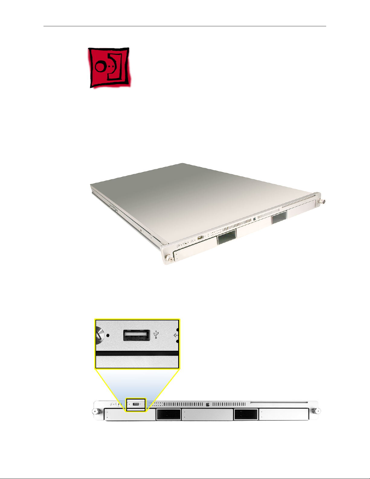
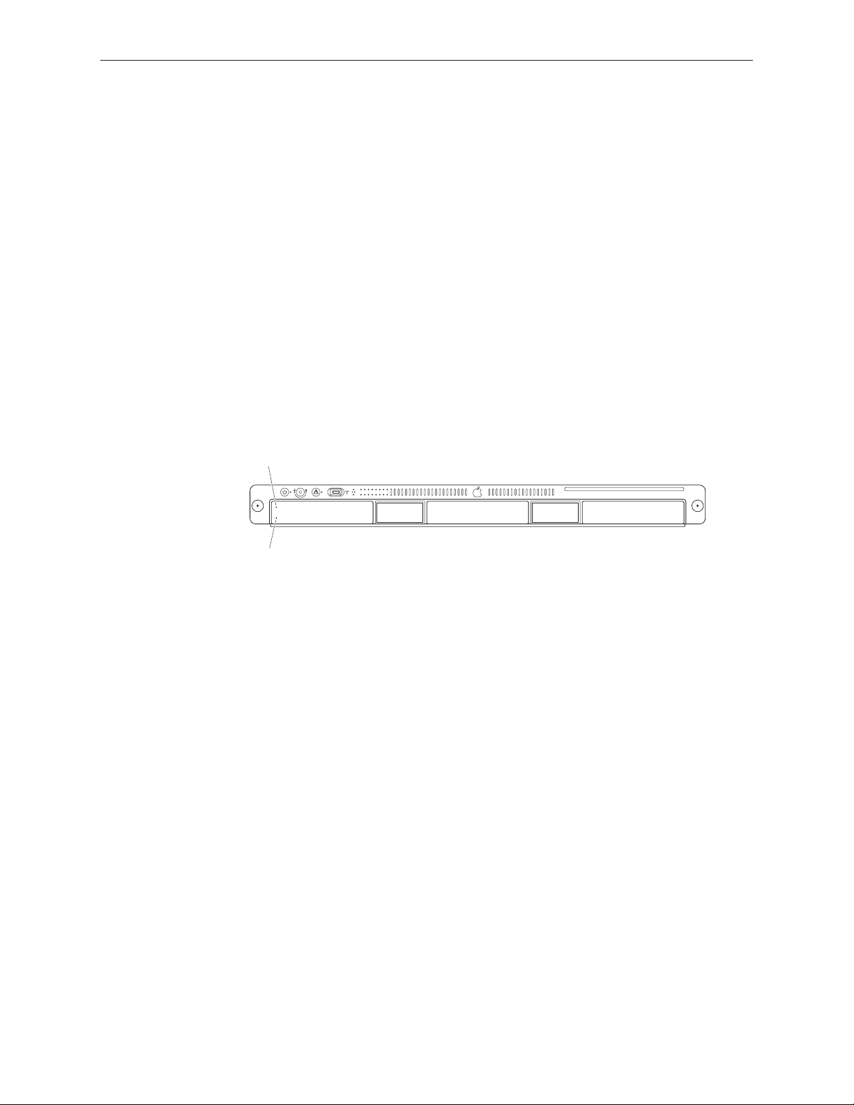
The only noticeable external dierence between the Xserve (Late 2006) model and the Xserve
(Early 2008) model is the port next to the system identier button on the front bezel. On the
Xserve (Late 2006) model, it is a FireWire 400 port; whereas on the Xserve (Early 2008) model, it is
a USB port, as shown below.
Xserve (Late 2006) Take Apart — General Information 8
Page 9
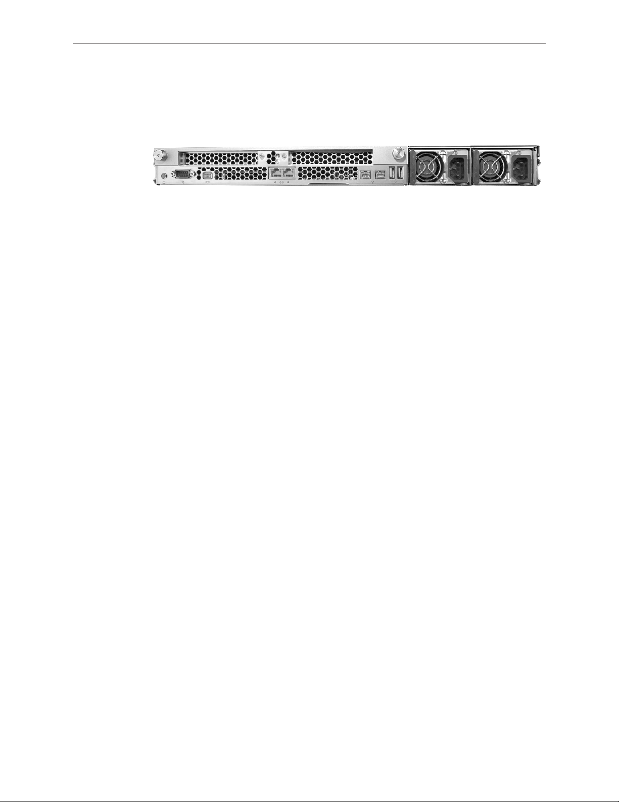
To distinguish the Xserve (Late 2006 or Early 2008) models from the previous Xserve G5 model,
check the rear panel. Xserve (Late 2006) and Xserve (Early 2008) have two power supply bays on
the right side of the rear panel. Previous Xserve G5 models have a single, built-in power supply.
What’s New
See “General Information” in the Troubleshooting chapter for an overview of new features in the
Xserve models.
Front and Rear Panel Ports and Indicators
See “External Views” in the Views chapter for descriptions of all front and rear panel ports,
switches, buttons, and LED indicator lights.
Mounting in a Rack
For information on mounting Xserve (Late 2006) in a rack, see the Xserve (Late 2006) Setup
Guide.
Tools
You will need the following tools:
Phillips #2 scewdriver•
Phillips #1 screwdriver•
Small at-blade screwdriver•
Nylon probe tool or similar plastic pry tool•
Needlenose pliers•
If the Xserve is locked, you will also need the Xserve’s Allen wrench key.
Note: Many take-apart procedures do not require tools because several internal components are
fastened with thumbscrews for easy removal and replacement.
Server Identier Light/Button
The identier light on the Xserve’s front panel turns on when internal sensors or a systems
administrator detects a problem with the Xserve. (The light can also be turned on by pressing
the identier button.) This indicator will help you locate which Xserve in a rack needs servicing.
Xserve (Late 2006) Take Apart — General Information 9
Page 10

In addition, you can use the identier button to select several alternative startup methods
from the front panel. See “Selecting an Alternative Startup Method from the Front Panel” in the
Troubleshooting chapter.
Note: A duplicate identier light/button is on the Xserve’s back panel.
A Note on the Images
The photos and drawings in this manual were based on a pre-production unit. Your Xserve may
look slightly dierent from the one shown in the images. Likewise, the instructions apply to more
than one Xserve model. Unless exceptions are noted, the steps and sequence are the same for
each model.
Xserve (Late 2006) Take Apart — General Information 10
Page 11
Apple Drive Module
Xserve (Late 2006) includes three hard drive bays on the front panel. Hard drives come as
modules, known as Apple drive modules (ADMs), attached to carriers; they are removed from or
installed in the Xserve as a unit. ADMs have been available from Apple in various capacities for
all Xserve and Xserve RAID models, and in multiple interface types. Xserve G4 and Xserve RAID
use parallel ATA (PATA) ADMs, and Xserve G5 uses serial ATA (SATA) ADMs. Xserve (Late 2006) can
use SATA ADMs, and ADMs with a new, third interface type known as serial attached SCSI (SAS).
It is important to understand ADM forward compatibility and backward compatibility with older
Xserve models, since some combinations of ADM and Xserve or RAID work properly while other
combinations do not. The following table summarizes this compatibility.
Xserve G4 Xserve RAID Xserve G5 Xserve
(Late 2006)
PATA ADM for
Xserve G4
SATA ADM for
Xserve G5
SATA ADM for
Xserve (Late 2006)
SAS ADM for Xserve
(Late 2006)
* PATA connector is physically dierent from SATA connector so this ADM will not t completely
into slot.
† PATA connector is physically dierent from SAS connector so this ADM will not t completely
into slot.
†† Will t completely into slot but ADM will not work or be recognized by the Xserve. Installing
the SAS ADM should not damage the drive, however.
Note: Blank drive carriers, which may ll some of the hard drive bays, follow the same take-apart
procedure as hard drives. If you are replacing a blank carrier with a drive module, instruct the
Xserve’s administrator to keep the blank for possible future use. Blank carriers must be installed in
all empty bays to maintain proper airow through the Xserve.
OK OK NO* NO* NO*
NO* NO* OK OK (but not
supported)
NO* NO* OK (but
not
supported)
NO† NO† NO†† OK OK
OK OK
Xserve (Early
2008)
OK (but not
supported)
Tools
No tools are required for this procedure.
Xserve (Late 2006) Take Apart — Hard Drive Module 11
Page 12
Backing Up Your Data
Drive module activity light (blue)
Drive module status light (green)
Warning: Before replacing the hard drive, make sure you back up all data on the drive.
Preliminary Steps
Before you begin, make sure the drives are in the unlocked position. Also, make sure the drive
being replaced is not in use by any application and is not being shared by the Xserve. (See the
Mac OS X Server documentation for information about shared drives.) To do this, you may need
to rst unmount the drive by using the command-line tools or by dragging the disk icon to the
Trash.
You can replace or install hard drives while the Xserve is running; you do not need to shut down
or open the Xserve rst.
Note: There are two LED indicators on the front of each drive.
The upper LED shows drive status: a green light indicates the drive is good; a yellow or red •
light indicates the drive should be replaced.
The lower LED shows drive activity: when the blue light is blinking, the system is reading •
from or writing to the drive. To avoid losing data, never remove a drive when the lower LED
is blinking.
Warning: Drives must be in the unlocked position before you attempt to remove a drive. If the
drives are locked, pulling on the drive to remove it could damage the drive handle.
Xserve (Late 2006) Take Apart — Hard Drive Module 12
Page 13
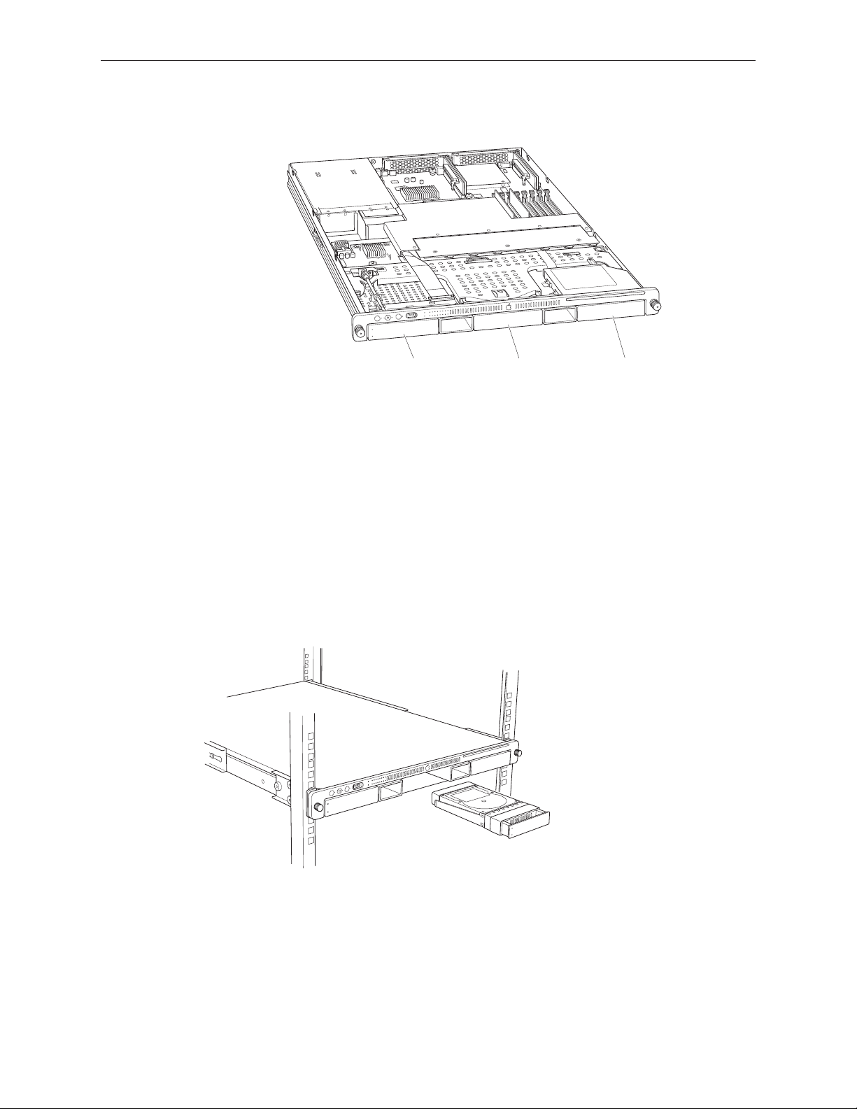
Part Location
Drive bay 1Drive bay 2Drive bay 3
Procedure
Make sure the drive being replaced is not in use by any application and is not being shared 1.
by the Xserve. (See the Mac OS X Server documentation for information about shared drives.)
Unmount the drive (by using the command-line tools or by dragging the volume icon to the 2.
Trash).
Press the handle on the front of the drive module so that the handle pops out. Wait for the 3.
upper LED on the drive to go out. Then grasp the drive handle, and pull the drive module
out of the Xserve.
Replacement Note: Press and release the handle on the replacement drive to open it, and slide
the module into the bay until it is rmly seated. Then press the handle in ush with the front
panel. The disk status light will turn green to indicate normal operation.
Xserve (Late 2006) Take Apart — Hard Drive Module 13
Page 14

Formatting the Hard Drive
If you replaced the hard drive with a new one, format the new hard drive by following the steps
presented here:
Start up from the Install Disc that came with your server, and choose the language.1.
From the menu bar, choose Utilities > Disc Utility.2.
To format the primary drive, use the Disc Utility on the Install disc.3.
Click the Partition tab.4.
Click on Options, and verify GUID is selected if this is the startup drive.5.
Name the volume “Macintosh HD.”6.
Apply the change by clicking the Partition tab.7.
Leave the Disc Utility application open, and restore the backed up les from the image you 8.
created before removing the hard drive.
Xserve (Late 2006) Take Apart — Hard Drive Module 14
Page 15
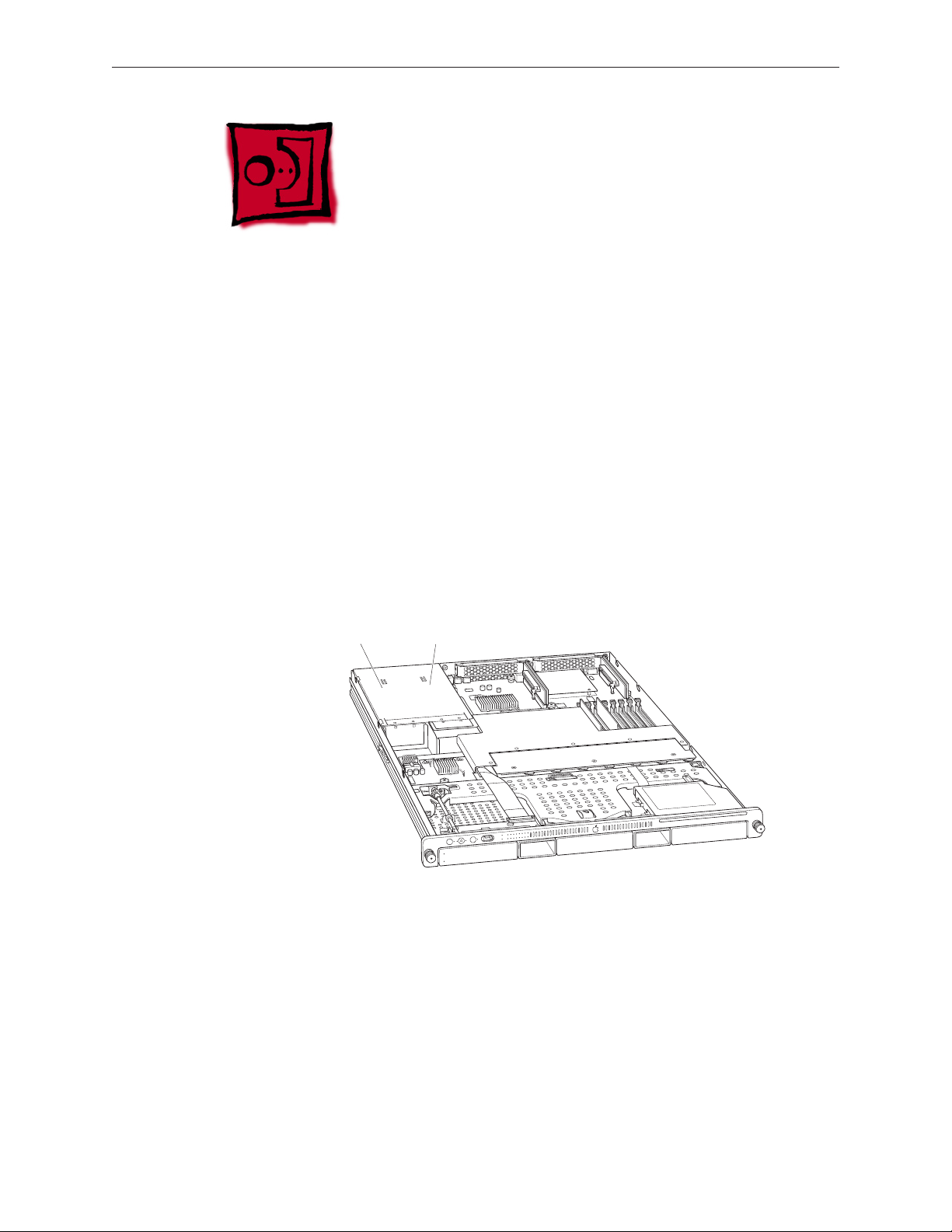
Power Supply
Power supply
bay 2
Power supply
bay 1
You can replace or install a power supply from the back panel without removing the server from
the rack. If the Xserve has two power supplies, they are hot-swappable; the Xserve will continue
to operate using only one supply while the second is removed.
Tools
No tools are required for this procedure.
Preliminary Steps
There are no preliminary steps for this procedure.
Part Location
Xserve (Late 2006) Take Apart — Power Supply 15
Page 16
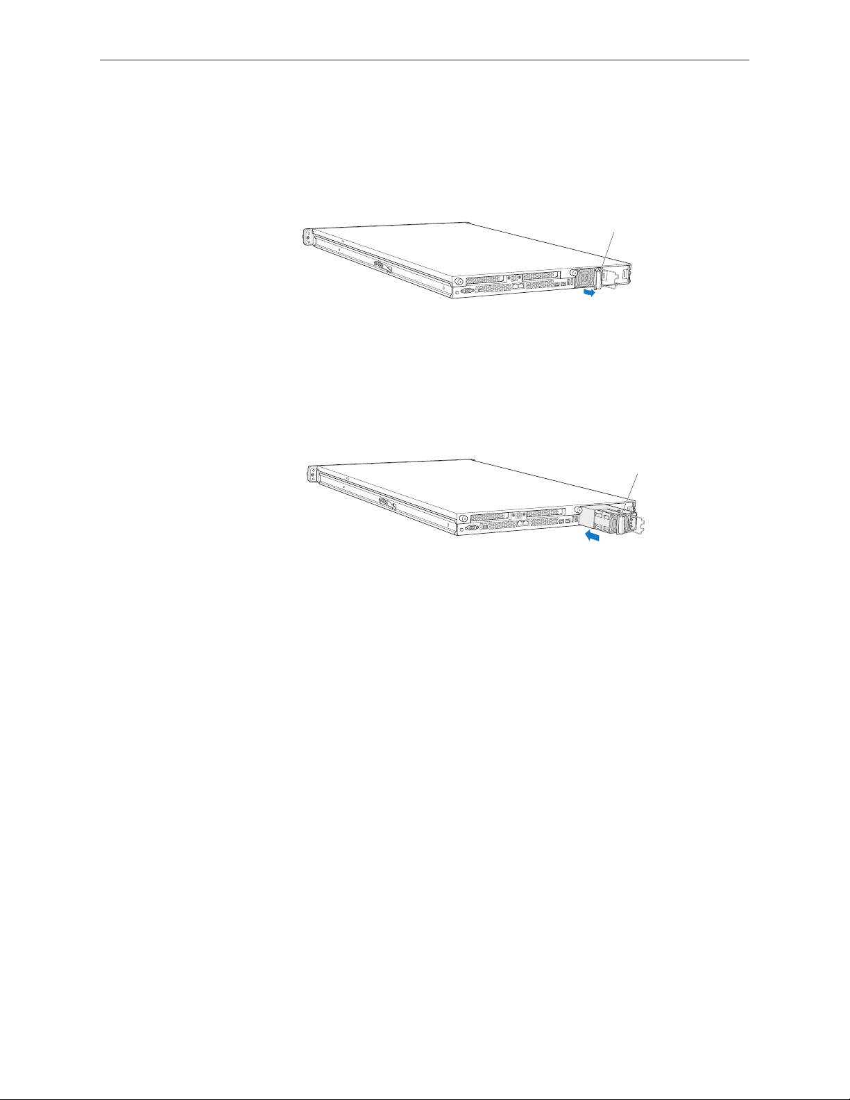
Procedure
Pull the handle to unlatch the
power supply and remove it.
Slide the power supply in and
press the handle to seat it.
Unplug the power cord from the power supply you are removing.1.
Pull the handle to release the power supply and slide it out of the bay.2.
Replacement Procedure
Press and release to open the handle on the new power supply, slide it all the way into the 1.
bay, and then press the handle to seat the power supply and lock it in place.
Connect the power cord to the power supply. 2.
Note: If the Xserve is already running on a second power supply, the status light on the new
supply turns green to indicate normal operation as it starts sharing the load. If the Xserve is
not turned on, the supply status light blinks green when the power cord is plugged in to an
outlet with power.
Xserve (Late 2006) Take Apart — Power Supply 16
Page 17
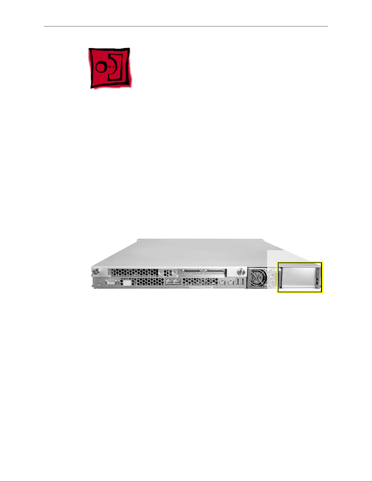
Power Supply Blank
If the server has only one power supply, the other bay is covered by a removable door. Called
a power supply blank, this door keeps the empty bay clean. The power supply blank may be
removed while the server is still in the rack.
Tools
No tools are required for this procedure.
Preliminary Steps
There are no preliminary steps for this procedure.
Part Location
Xserve (Late 2006) Take Apart — Power Supply 17
Page 18
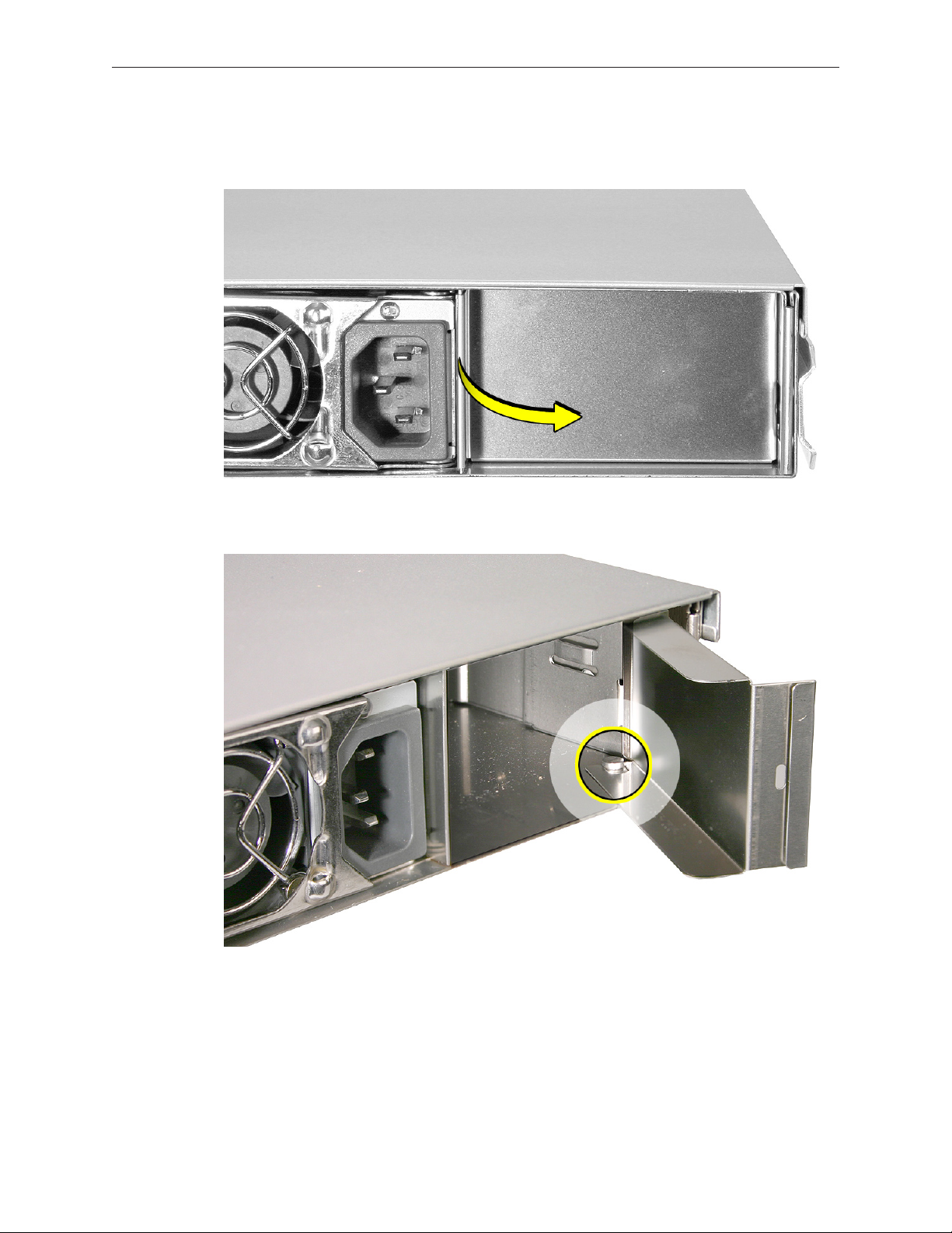
Procedure
Pull out the handle to swing open the power supply blank.1.
Notice the hook that catches on the inside bottom of the power supply bay. 2.
Xserve (Late 2006) Take Apart — Power Supply 18
Page 19
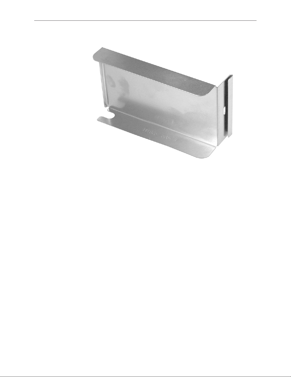
Open the power supply blank as far as it will go, and then pull out the power supply blank.3.
Replacement Note: Align the hook on the power supply blank with the catch inside the power
supply bay. Close the power supply blank, and press the handle over the bay wall to lock it in
place.
Xserve (Late 2006) Take Apart — Power Supply 19
Page 20
Opening the Top Cover
The top cover on this Xserve model does not remain installed in the rack as it did in previous
Xserve G5 models. The entire Xserve enclosure, including its top cover, must be removed
from the rack as a unit before the top cover can be removed to gain access to any internal
components.
Tools
No tools are required for this procedure. You may, however, nd a Phillips screwdriver useful in
releasing the thumbscrews.
Preliminary Steps
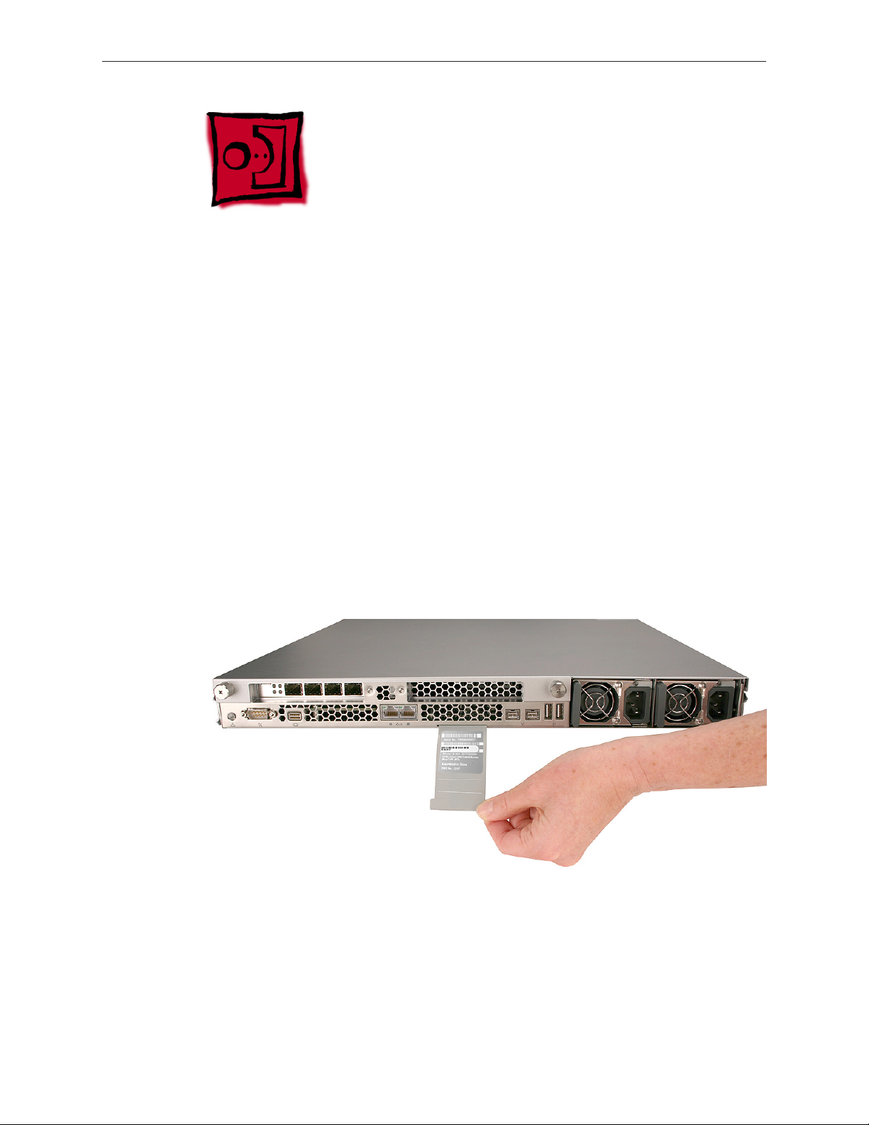
Serial Number
Be sure to write down the Xserve’s serial number. If the Xserve’s software must be set up after
service is complete, the serial number will be required for login. The serial number is located on
a pull-out tab at the bottom-center of the rear panel.
Xserve (Late 2006) Take Apart — Opening the Top Cover 20
Page 21
Unlocking the Server
If the Xserve is in the locked position (the yellow security LED on the front panel is on), use the
Allen key that came with the Xserve to unlock it. The lock secures the Xserve enclosure top cover
and all three drive modules. You can also order spare keys using Apple part number 922-6144.
Important: An option in the Security pane of System Preferences lets you inactivate a connected
keyboard and mouse when the enclosure lock is engaged. This option is turned o by default.
When the enclosure is locked (the light is on), the Xserve might not recognize peripheral devices
such as a keyboard, mouse, or storage device. Unlock the lock to use those devices.
Shutting Down
You must shut down the Xserve before replacing or installing all parts except the hard drives and
power supplies. Before shutting down, be sure to alert users that the Xserve will be unavailable
for a period of time.
Warning: Always shut down the Xserve before opening it to avoid damaging its internal
components or the components you want to install or remove. Don’t open the Xserve or try
to install or remove items inside while it is turned on. Even after you shut down the Xserve, its
internal components can be very hot. Let it cool down for 5 to 10 minutes before you open it..
Part Location
Procedure
Shut down the Xserve (see the Xserve User’s Guide for help) and then wait a few moments 1.
to let the Xserve internal components cool.
If the Xserve case is locked, use the enclosure key to unlock the security lock on the front 2.
panel.
Unplug all cables from the Xserve. 3.
Note: If you have trouble releasing a cable from the back panel, try using a small screwdriver
or other at tool to depress the tab on the cable connector.
Xserve (Late 2006) Take Apart — Opening the Top Cover 21
Page 22
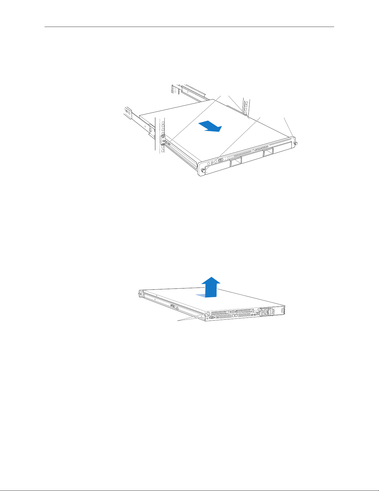
Loosen the thumbscrews at both ends of the front panel.4.
Latches
Thumbscrews
Unscrew the two
captive thumbscrews.
Slide the cover back and lift it off.
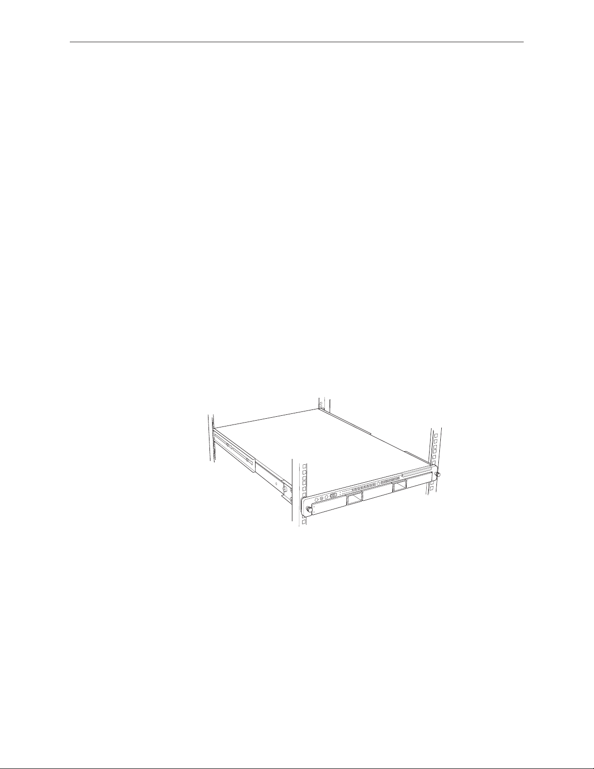
Grasp the thumbscrews and pull the Xserve forward until the safety latches engage (about 5.
halfway out of the rack).
When the safety latches engage, grip the Xserve where it emerges from the rack, press down 6.
on the latch tabs with your thumbs, and slide the Xserve the rest of the way out of the rack
rails. Set the Xserve on a at surface.
Loosen the thumbscrews at the back of the top cover and slide the cover back and up to 7.
remove it. If you have diculty removing the cover, check the enclosure lock on the front
panel.
Important: To minimize the possibility of damage to Xserve components due to static
discharge, wear an antistatic wrist strap while you work inside the Xserve.
When you’re nished working inside the Xserve, replace and secure the cover, slide the 8.
Xserve back into the rack, and tighten the front thumbscrews to secure the Xserve in the
rack. If the server case was locked, use the enclosure key to lock the security lock on the front
panel.
Xserve (Late 2006) Take Apart — Opening the Top Cover 22
Page 23
FB-DIMM Memory
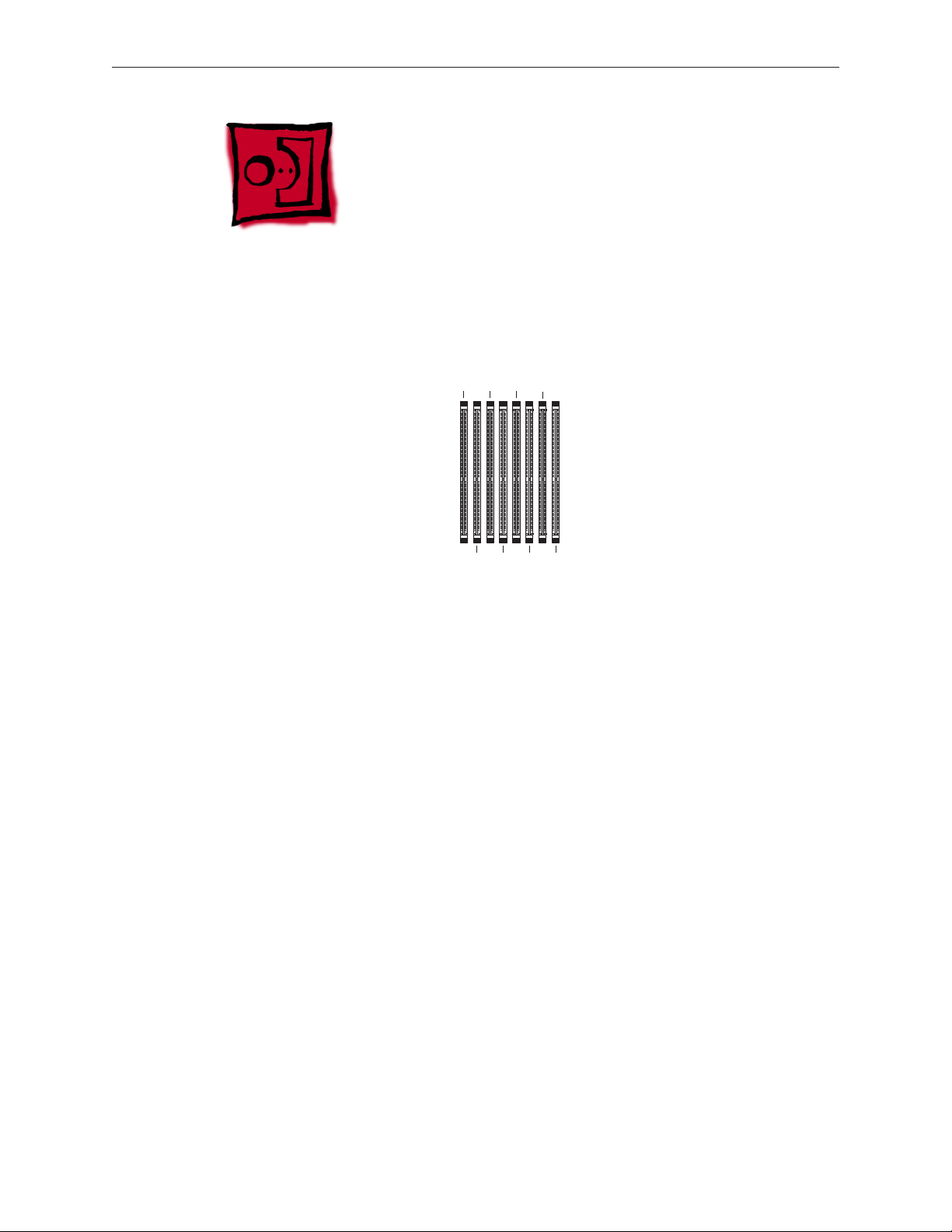
1234
5678
The Xserve (Late 2006) has 8 memory slots. The systems come with at least 1 gigabyte (GB) of
memory on two fully-buered dual inline memory modules (FB-DIMMs). To improve performance
and capacity, you can install additional DIMMs for a total of up to 32 GB of memory. The 8
memory slots are labeled DIMM 1 through DIMM 8.
You can use the following memory in the Xserve (Late 2006):
667 MHz DDR2 ECC FB-DIMMs •
512 MB, 1 GB, 2 GB, or 4 GB in matching pairs (optimal, 4 or 8 identical DIMMs) •
36 devices per DIMM, maximum •
Error-correcting code (ECC) •
Important: Apple recommends that you use Apple-approved FB-DIMMS. Other FB-DIMMs might
degrade the performance of the Xserve. DIMMs from older Xserve systems are not compatible
with this Xserve.
Note: Before you purchase DIMMs other than those recommended by Apple, make sure that
the memory manufacturer conforms to the Joint Electronic Device Engineering Council (JEDEC)
specication. Make sure that the DIMMs support the correct timing modes and that the Serial
Presence Detect (SPD) feature has been implemented in accordance with the JEDEC specication.
To check DIMM compatibility, see the Macintosh Products Guide on Apple’s website at www.
apple.com/guide. You can purchase Apple-approved memory online from the Apple Store at
www.apple.com/store.
Xserve (Late 2006) Take Apart — FB-DIMM Memory 23
Page 24
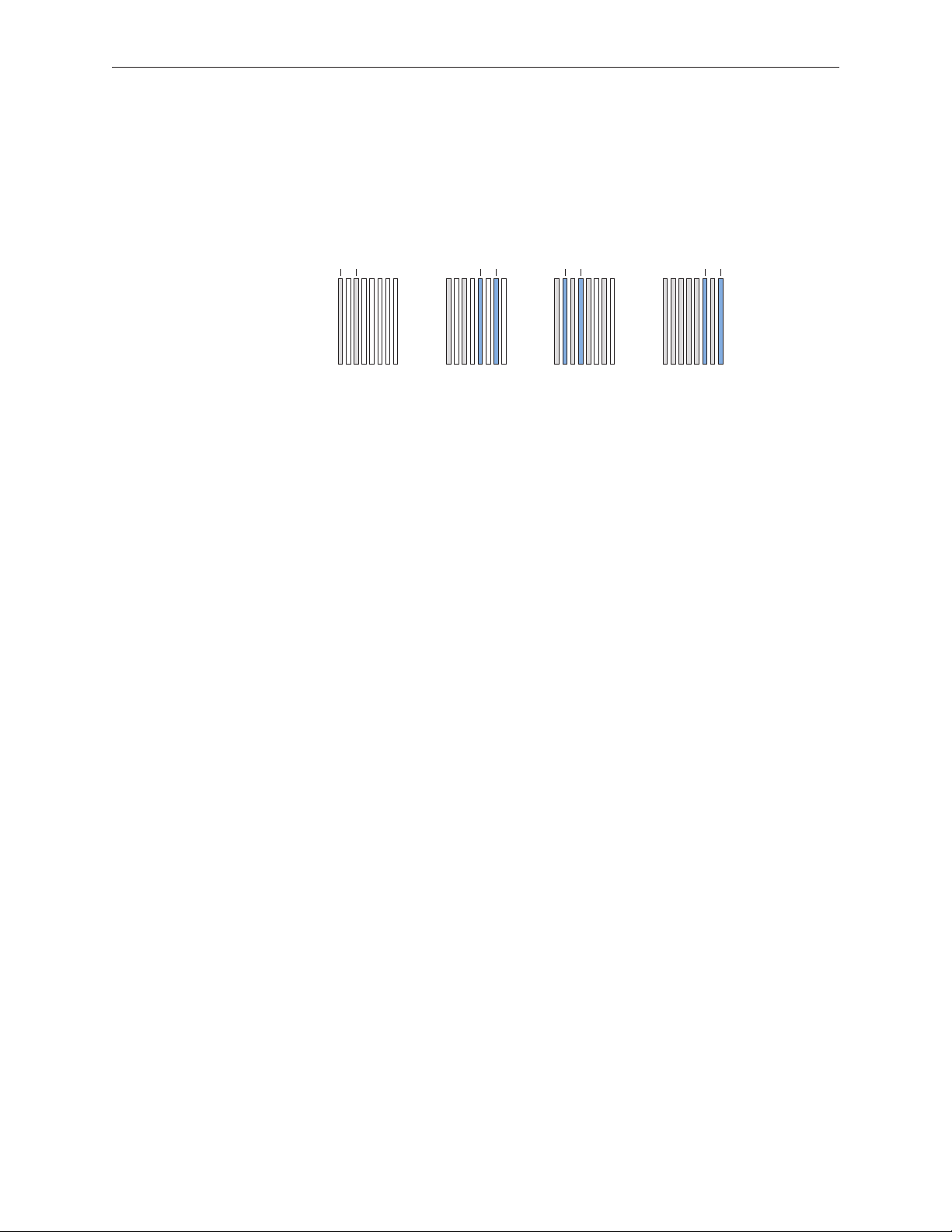
Installation Rules
The server comes
with at least 2 DIMMs
Add the next pair
in these two slots
(Back)
12 34 56 78
(Front)
Add the next pair
in these two slots
Add the next pair
in these two slots
You must install DIMMs in pairs, and the DIMMs in each pair must be identical (the same
size, speed, etc.). The rst pair is installed in slots 1 and 2. Install the next pair in slots 3 and 4.
Subsequent pairs go in slots 5 and 6, and then slots 7 and 8.
For Best Performance
For the best performance, use identical DIMMs in all slots and ll up slots 1 through 4 before you
install DIMMs in slots 5 through 8. If you don’t have eight identical DIMMs, install identical DIMMs
in slots 1 through 4 and a second set of four identical DIMMs in slots 5 through 8. If you can, after
you ll slots 1 through 4, add a full set of four DIMMs in slots 5 through 8 instead of just a pair in
slots 5 and 6.
Tools
No tools are required for this procedure.
Preliminary Steps
Before you begin, open the Xserve and place the bottom housing on a sturdy, at surface.
Xserve (Late 2006) Take Apart — FB-DIMM Memory 24
Page 25
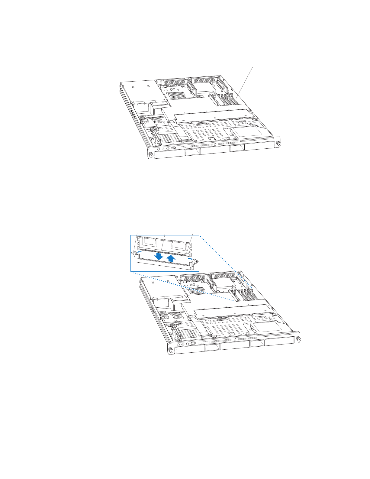
Part Location
DIMM slots (8)
ConnectorsNotchEjectors
Procedure
Push down the ejectors on the DIMM slot.1.
Holding the DIMM by both top corners, lift it straight up out of the Xserve.2.
Warning: When removing or installing the DIMM, handle it only by the edges. Do not touch
its connectors. Lift the DIMM straight up from the connector to remove it, and insert it straight
down into the connector to install it. Do not rock the DIMM from side to side.
Replacement Note: The DIMM is designed to t into the slot only one way. Be sure to align the
notch in the DIMM with the small rib inside the slot.
Xserve (Late 2006) Take Apart — FB-DIMM Memory 25
Page 26
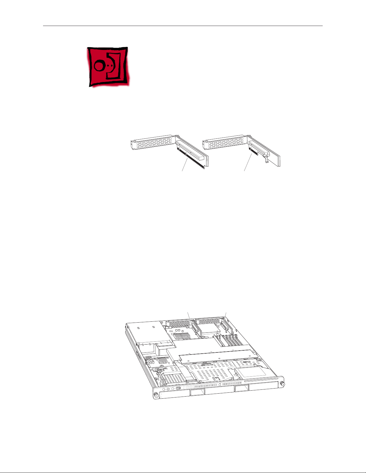
PCI-X and PCI-E Riser Cards
Connector on PCI-X riser Connector on PCI-E riser
Expansion slot 1
(PCI-E or PCI-X)
Expansion slot 2
(PCI-E)
This Xserve model uses two types of PCI riser cards to accommodate expansion card installation:
A PCI-E riser card, which can go in either slot, and accepts only PCI-E cards •
A PCI-X riser can go in slot 1, and accepts only PCI-X cards •
Tools
The only tool required for this procedure is a Phillips #1 screwdriver.
Preliminary Steps
Before you begin, open the Xserve and place the bottom housing on a sturdy, at surface.
Important: Be sure the Xserve is turned o and unplugged before you install or remove an
expansion card or riser.
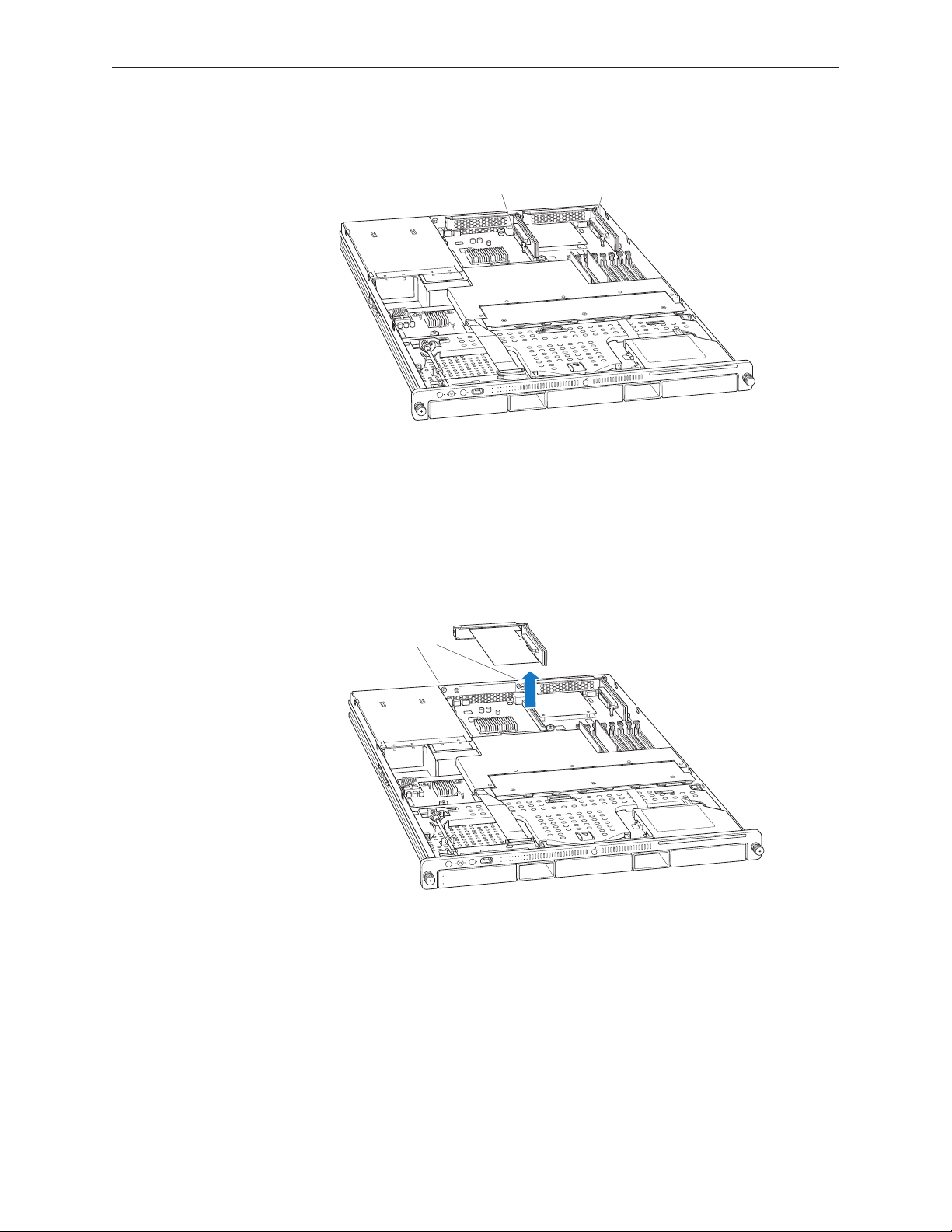
Part Location
Xserve (Late 2006) Take Apart — PCI-X and PCI-E Riser Cards 26
Page 27

Procedure
Captive screws
Screw
PCI card
PCI riser
Loosen the two captive screws that secure the riser bracket to the back panel. 1.
Carefully pull up on the bracket and riser, to disconnect the riser from the logic board. If you 2.
are removing a blank riser card so that you can install a graphics card in the riser, do the
following:
Remove the screw on the riser bracket and remove the port access cover.•
Seat the PCI card in the riser slot and replace the screw to secure the card in the riser. •
If you are removing a riser card so that you can replace it with a new riser card, remove any 3.
expansion card installed in the original riser card and transfer the card to the replacement
riser.
Xserve (Late 2006) Take Apart — PCI-X and PCI-E Riser Cards 27
Page 28

PCI-X and PCI-E Expansion Cards
This Xserve model has two expansion slots:
Slot 1, which accepts full-length (9 inch) PCI-E or PCI-X cards•
Slot 2, which accepts half-length (6.6 inch) PCI-E cards •
The server accepts expansion cards that meet these specications:
Slot 1:
Accepts 64-bit PCI-X 133 MHz cards (using a PCI-X riser) •
Also accepts 32-bit or 64-bit 33, 66, or 100 MHz PCI or PCI-X cards with 3.3 volt universal •
signaling
Also accepts PCI-E x8 cards (using a PCI-E riser) •
9 inch maximum length •
25 Watt maximum power consumption •
Slot 2:
Accepts PCI-Express x8 cards (using a PCI-E riser)•
6.6 inch maximum length •
25 Watt maximum power consumption•
To install a card, you rst insert it into a matching riser, and then install the riser into the slot. The
type of card you can install depends on the riser you use:
A PCI-E riser can go in either slot, and accepts only PCI-E cards •
A PCI-X riser can go in slot 1, and accepts only PCI-X cards •
Tools
The only tool required for this procedure is a Phillips #1 screwdriver.
Preliminary Steps
Before you begin, open the Xserve and place the bottom housing on a sturdy, at surface.
Important: Be sure the Xserve is turned o and unplugged before you install or remove an
expansion card or riser.
Xserve (Late 2006) Take Apart — PCI-X and PCI-E Expansion Cards 28
Page 29
Part Location
Expansion slot 1
(PCI-E or PCI-X)
Expansion slot 2
(PCI-E)
Captive screws
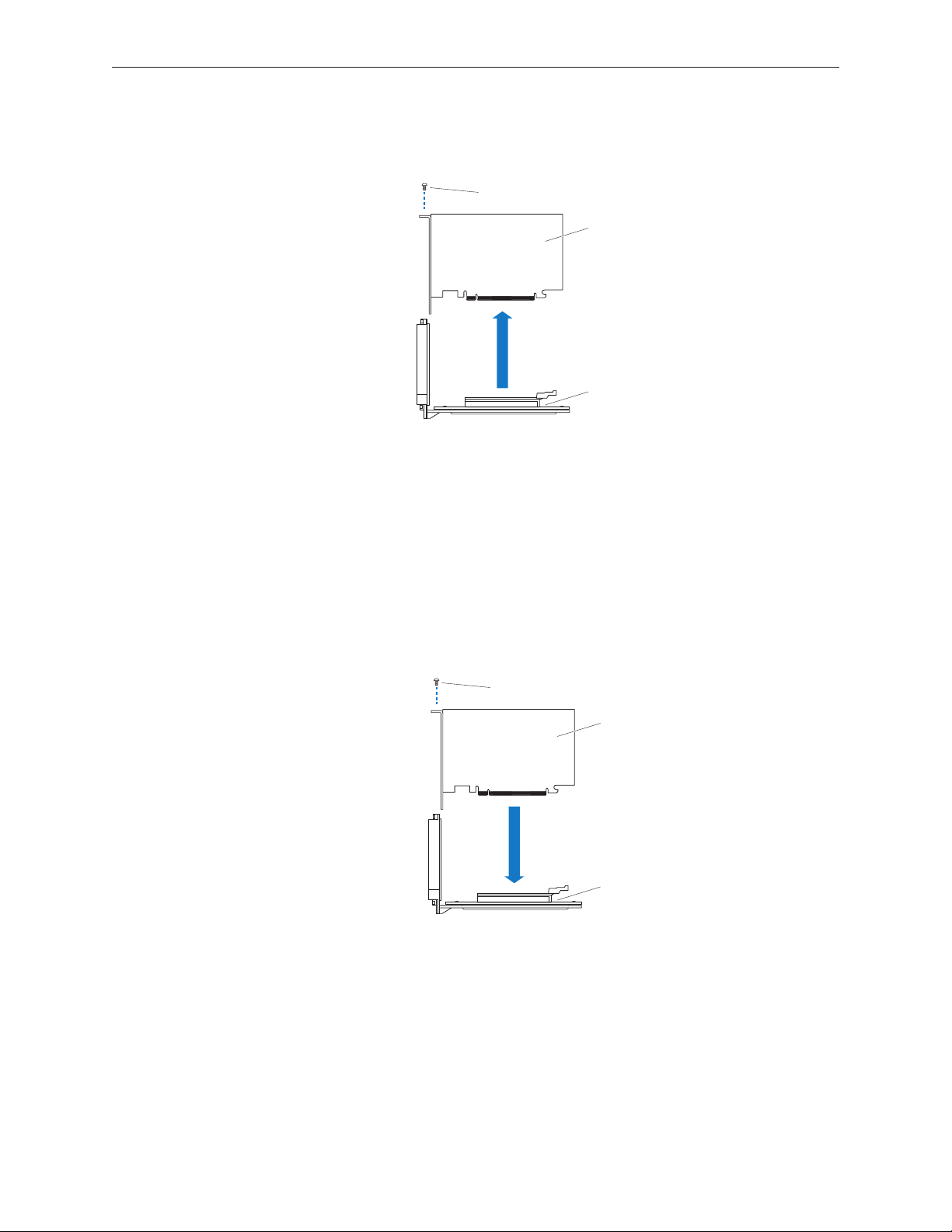
Procedure
Loosen the two captive screws that secure the riser bracket to the back panel.1.
Carefully pull up on the bracket and riser, with the expansion card still attached, to 2.
disconnect the riser from the logic board.
Tilt the expansion card up so that its port clears the enclosure, and remove the card from the 3.
Xserve.
Xserve (Late 2006) Take Apart — PCI-X and PCI-E Expansion Cards 29
Page 30
Remove the screw that secures the expansion card to the riser, and separate the card and 4.
Screw
PCI card
PCI riser
Screw
PCI card
PCI riser
riser by gently pulling them apart.
WARNING: When removing or installing an expansion card, handle it only by the edges. Do not
touch its connectors or any of the components on the card. Lift the card straight out from the
connector to remove it, and insert it straight into the connector to install it. Do not rock the card
from side to side and don’t force the card into the slot. Once the replacement card is installed,
pull on it gently to check that it is properly connected.
Replacement Procedure
Seat the expansion card in the riser slot and replace the screw to secure the card in the riser. 1.
Xserve (Late 2006) Take Apart — PCI-X and PCI-E Expansion Cards 30
Page 31

Align the riser with the slot on the logic board and press to seat the card. 2.
Tighten the captive screws that secure the riser bracket to the back panel.3.
Return the Xserve to the rack and start it up.4.
Congure the card. 5.
• To congure an Ethernet card, open the Network pane of System Preferences.
• To congure a Fibre Channel card, open Fibre Channel Utility.
• To congure a SCSI card, open Disk Utility.
Xserve (Late 2006) Take Apart — PCI-X and PCI-E Expansion Cards 31
Page 32

Battery in Xserve (Late 2006)
Battery
The Xserve (Late 2006) uses a CR 2032 Lithium coin cell battery to preserve settings such as
the date and time when the system is not connected to power. If the date and time change
unexpectedly or other system settings are lost, you might need to replace the battery.
Tools
No tools are required for this procedure. You may, however, nd a small plastic pry tool useful in
prying up the battery in step 1 below.
Preliminary Steps
Before you begin, open the Xserve and place the bottom housing on a sturdy, at surface.
Part Location
Xserve (Late 2006) Take Apart — Battery in Xserve (Late 2006) 32
Page 33

Procedure
The negative
(–)
side faces away from the power supply.
Remove the left riser card and any installed expansion card in slot 1 if it blocks access to the 1.
battery holder.
Remove the old battery from the holder. 2.
Note: You may rst need to carefully spread the two tabs on the holder slightly apart to
release the battery.
Warning: To avoid risk of explosion, replace battery only with type CR2032.
Insert the new battery in the holder with the positive side (+) facing the power supply, and 3.
the negative side facing toward the center of the Xserve.
If you removed a riser card and/or an expansion card, replace it.4.
Close the Xserve and return it to the rack.5.
Important: Dispose of the old battery according to the manufacturer’s instructions and your
local environmental laws.
Xserve (Late 2006) Take Apart — Battery in Xserve (Late 2006) 33
Page 34

Battery in Xserve (Early 2008)
The Xserve (Early 2008) uses a CR 2032 Lithium coin cell battery to preserve settings such as
the date and time when the system is not connected to power. If the date and time change
unexpectedly or other system settings are lost, you might need to replace the battery.
Tools
No tools are required for this procedure. You may, however, nd a small plastic pry tool useful in
prying up the battery.
Preliminary Steps
Before you begin, open the Xserve and place the bottom housing on a sturdy, at surface.
Part Location
Xserve (Late 2006) Take Apart — Battery in Xserve (Early 2008) 34
Page 35

Procedure
Remove the old battery from the holder. 1.
Note: You can insert a plastic pry tool under the battery to ease the grip between the spring
and the holder. Then slide out the battery.
Warning: To avoid risk of explosion, replace battery only with type CR2032.
Insert the replacement battery in the holder with the positive side (+) up and the negative 2.
side down.
Important: Dispose of the old battery according to the manufacturer’s instructions and your
local environmental laws.
Close the Xserve and return it to the rack.3.
Xserve (Late 2006) Take Apart — Battery in Xserve (Early 2008) 35
Page 36

Optical Drive
Note: Although some of the illustrations for this procedure are based on Xserve G5, the
procedure is the same for Xserve (Late 2006) and Xserve (Early 2008).
Tools
The only tool required for this procedure is a jeweler’s Phillips (#0) screwdriver.
Preliminary Steps
Before you begin, open the Xserve and place the bottom housing on a sturdy, at surface.
Part Location
Xserve (Late 2006) Take Apart — Optical Drive 36
Page 37

Procedure
Disconnect the optical drive cable from the optical drive. 1.
Rotate the optical drive clip clockwise to release it.2.
Placing your thumbs on the tab on either side of the drive, carefully slide the drive back from 3.
the front bezel.
Important: When removing or replacing the optical drive, be careful not to put pressure on
the top of the drive or the top of the front bezel that covers the optical drive slot.
LIft the drive out of the server. 4.
Xserve (Late 2006) Take Apart — Optical Drive 37
Page 38

Replacement Note: Before installing the replacement drive, you must transfer the side
brackets and the screws from the original drive to the replacement drive.
Remove the mounting screw for the left bracket and transfer the bracket to the new drive, 5.
using the same screw to secure it.
Remove the three mounting screws for the right bracket and transfer the bracket to the new 6.
drive, again using the same screws to secure it.
Xserve (Late 2006) Take Apart — Optical Drive 38
Page 39

Airow Duct
Tools
The only tool required for this procedure is a Phillips #1 screwdriver
Preliminary Steps
Before you begin, open the Xserve and place the bottom housing on a sturdy, at surface.
Part Location
Xserve (Late 2006) Take Apart — Airow Duct 39
Page 40

Procedure
Loosen the ve Phillips screws that fasten the airow duct to the fan array.1.
Pull up on either side of the airow duct, and lift it straight up and out of the Xserve. 2.
Caution: Try not to completely remove the screws from the airow duct. Tiny black rubber
washers hold these screws captive on the underside of the airow duct. If the screws are
completely removed, these rubber washers can easily fall into the enclosure and become
lost.
Xserve (Late 2006) Take Apart — Airow Duct 40
Page 41

Replacement notes:
When installing the airow duct, be sure to route both the front panel cable and the •
backplane-to-logic board I/O cable inside the channel under the left side of the duct.
Ensure the airow duct ts ush all over, and does not protrude above the level of the •
enclosure.
Be careful when working with any black foam pieces that are part of the airow duct or the •
logic board.
Tighten the ve Phillips screws that fasten the airow duct to the fan array, in the order •
shown, to prevent the duct from warping. Do not overtighen the screws.
Xserve (Late 2006) Take Apart — Airow Duct 41
Page 42

Fan Array
Tools
No tools are required for this procedure. You may, however, nd a Phillips screwdriver useful in
releasing the thumbscrews in step 1 below.
Preliminary Steps
Before you begin, do the following:
Open the Xserve and place the bottom housing on a sturdy, at surface.•
Remove the airow duct.•
Part Location
Xserve (Late 2006) Take Apart — Fan Array 42
Page 43

Procedure
Loosen the two thumbscrews that secure the fan array to the enclosure. 1.
Note: The thumbscrews are captive; you cannot remove them.
Lift the fan array to remove it from the Xserve. 2.
Note: You may need to move the front panel cable slightly out of the way of the fan array
power connector during removal or replacement. Be careful not to pinch the front panel
board cable between the fan array and any other surface inside.
Replacement Note: Push down on the fan array power connector to seat it when installing
the fan array.
Xserve (Late 2006) Take Apart — Fan Array 43
Page 44

If you feel some resistance from the power connector during removal, carefully rotate the fan 3.
array as shown to disconnect it from the power distribution board. Then lift the fan array out
of the computer.
Replacement Note: When installing the fan array, make sure a foam strip is included, as
shown below.
Xserve (Late 2006) Take Apart — Fan Array 44
Page 45

Front Panel Board Cable
Tools
No tools are required for this procedure.
Preliminary Steps
Before you begin, do the following:
Open the Xserve and place the bottom housing on a sturdy, at surface.•
Remove the airow duct.•
Remove the left PCI riser card and any expansion card in slot 1.•
Part Location
Xserve (Late 2006) Take Apart — Front Panel Board Cable 45
Page 46

Procedure
Release the locking levers on the cable connectors and disconnect the front panel board 1.
cable from the front panel board and the logic board.
Remove the cable from the Xserve.2.
Xserve (Late 2006) Take Apart — Front Panel Board Cable 46
Page 47

Backplane-to-Logic Board I/O Cable
Tools
No tools are required for this procedure.
Preliminary Steps
Before you begin, do the following:
Open the Xserve and place the bottom housing on a sturdy, at surface.•
Remove the airow duct.•
Part Location
Xserve (Late 2006) Take Apart — Backplane-to-Logic Board I/O Cable 47
Page 48

Procedure
Disconnect the backplane-to-logic board cable from the logic board. 1.
Disconnect the backplane-to-logic board cable from the drive interconnect backplane and 2.
remove the cable from the Xserve.
Xserve (Late 2006) Take Apart — Backplane-to-Logic Board I/O Cable 48
Page 49

Replacement Note: Before installing the cable, fold it to a 90-degree angle along its creases.
Replacement Note: Connect the cable to the logic board rst. Then press the adhesive section of
the cable onto the enclosure before connecting the other end of the cable to the backplane.
Caution: Make sure the cable is fully seated.
Xserve (Late 2006) Take Apart — Backplane-to-Logic Board I/O Cable 49
Page 50

Optical Drive Cable
Tools
No tools are required for this procedure.
Preliminary Steps
Before you begin, do the following:
Open the Xserve and place the bottom housing on a sturdy, at surface.•
Remove the airow duct•
Remove the fan array•
Part Location
Xserve (Late 2006) Take Apart — Optical Drive Cable 50
Page 51

Procedure
Warning: The optical drive cable is attached to the enclosure with adhesive on the underside of
the cable.
Disconnect the optical drive cable from the optical drive.1.
Disconnect the optical drive cable from the logic board. 2.
Carefully pry the cable’s adhesive from the enclosure and remove the cable from the Xserve.3.
Replacement Note: Fold the replacement optical drive cable to 90-degree angles along its
creases.
Xserve (Late 2006) Take Apart — Optical Drive Cable 51
Page 52

Replacement Note: Connect the replacement optical drive cable to the logic board rst. Then
press the adhesive section of the cable onto the enclosure before connecting the other end of
the cable to the optical drive.
Xserve (Late 2006) Take Apart — Optical Drive Cable 52
Page 53

Locking Mechanism Rod
Note: Although some of the illustrations for this procedure are based on Xserve G5, the
procedure is the same for Xserve (Late 2006) and Xserver (Early 2008).
Tools
No tools are required for this procedure.
Preliminary Steps
Before you begin, open the Xserve and place the bottom housing on a sturdy, at surface.
Part Location
Xserve (Late 2006) Take Apart — Locking Mechanism Rod 53
Page 54

Procedure
Pull back the latch to release the gear end of the locking mechanism rod. 1.
Tilt up the gear end of the rod and remove the rod from the server. 2.
If you are replacing the plastic gear on the end of the rod, slide the gear o the rod.3.
Replacement Procedure
To install the gear, slide it onto the notched end of the locking rod, aligning the narrow end 1.
of the gear with the end of the rod.
Note: Make sure the rib inside the gear engages with the notch in the rod.
Xserve (Late 2006) Take Apart — Locking Mechanism Rod 54
Page 55

To install the locking rod, insert the key-hole end of the rod into the port on the front bezel. 2.
Note: Make sure the small circle on the front of the rod points to the left. It should align with
the “unlocked” symbol on the bezel.
Xserve (Late 2006) Take Apart — Locking Mechanism Rod 55
Page 56

Front Bezel Assembly for Xserve (Late 2006)
Note: Although the illustrations for this procedure are based on Xserve G5, the procedure is the
same for Xserve (Late 2006).
Tools
The only tool required for this procedure is a Phillips screwdriver.
Preliminary Steps
Before you begin, open the Xserve and place the bottom housing on a sturdy, at surface.
Part Location
Xserve (Late 2006) Take Apart — Front Bezel Assembly for Xserve (Late 2006) 56
Page 57

Procedure
Using a Phillips screwdriver, remove the screws that attach the two front bezel brackets to 1.
the server, and remove the brackets.
Remove the screw that attaches the top of the bezel to the server. 2.
Gently pull the front bezel forward and remove it from the server. 3.
Important: When removing or replacing the bezel, be careful not to put pressure on the top
of the bezel over the optical drive slot.
Xserve (Late 2006) Take Apart — Front Bezel Assembly for Xserve (Late 2006) 57
Page 58

Replacement Procedure
Transfer the power button and system identier button from the original front bezel to the 1.
replacement bezel.
Position the light pipes in the light pipe assembly into the double row of light pipe holes in 2.
the front bezel.
Replace the front bezel on the server, matching ports/projections with openings.3.
Replace the screw that secures the top of the bezel to the server.4.
Replace the two bezel brackets and their mounting screws.5.
Xserve (Late 2006) Take Apart — Front Bezel Assembly for Xserve (Late 2006) 58
Page 59

Front Bezel Assembly for Xserve (Early 2008)
Tools
The only tool required for this procedure is a Phillips screwdriver.
Preliminary Steps
Before you begin, open the Xserve and place the bottom housing on a sturdy, at surface.
Part Location
Removal Procedure
From behind the front bezel, locate the four screws and two brackets. Remove the four 1.
identical 4-mm long screws and the two brackets.
Remove the 8-mm long center screw (with star washer) that attaches the top of the bezel to 2.
the server.
Xserve (Late 2006) Take Apart — Front Bezel Assembly for Xserve (Early 2008) 59
Page 60

Gently pull the front bezel forward, and remove it from the server.3.
Important: When removing or replacing the bezel, be careful not to put pressure on the top
of the bezel over the optical drive slot.
Replacement Procedure
Leave the power button and system identier button on the server, but note that the 1.
button(s) could be loose. To prevent damage to the buttons, be sure to align the buttons
with the front panel openings as you install a replacement front bezel.
Xserve (Late 2006) Take Apart — Front Bezel Assembly for Xserve (Early 2008) 60
Page 61

Make sure the light pipe is secure in the front bezel. If it comes out, align the pins to the 2.
front bezel, and insert it into the slot in the front bezel.
Place the front bezel on the server, carefully matching openings with buttons and ports. 3.
Replace the bezel brackets, four 4-mm long screws, and 8-mm long center screw with star 4.
washer.
Xserve (Late 2006) Take Apart — Front Bezel Assembly for Xserve (Early 2008) 61
Page 62

Front Bezel Brackets for Xserve (Early 2008)
Tools
The only tool required for this procedure is a Phillips screwdriver.
Preliminary Steps
Before you begin, open the Xserve and place the bottom housing on a sturdy, at surface.
Part Location
Xserve (Late 2006) Take Apart — Front Bezel Brackets for Xserve (Early 2008) 62
Page 63

Removal Procedure
From behind the front bezel, remove the four identical 4-mm long screws and the two brackets.
Important: When removing or replacing the bezel brackets, be careful not to put pressure on the
top of the bezel over the optical drive slot.
Replacement Procedure
Position the right replacement bracket on the server, and install its two mounting screws.1.
Repeat for the left replacement bracket. 2.
Xserve (Late 2006) Take Apart — Front Bezel Brackets for Xserve (Early 2008) 63
Page 64

Front Panel Buttons
Note: This procedure explains how to remove the power and system ID buttons from the front
bezel.
Tools
The only tool required for this procedure is a Phillips screwdriver.
Preliminary Steps
Before you begin, open the Xserve; place the bottom housing on a sturdy, at surface; and
remove the front bezel assembly.
Part Location
Xserve (Late 2006) Take Apart — Front Panel Buttons 64
Page 65

Procedure
Holding the power button by the plastic tab, lift straight up and remove the button from the 1.
front bezel.
Repeat for the system ID button. 2.
Note: Take care in handling the buttons. The face of each button is loosely attached to the
button LEDs and can easily separate.
Replacement Note: Position the replacement buttons in the front bezel as illustrated.
Xserve (Late 2006) Take Apart — Front Panel Buttons 65
Page 66

Light Pipe for Xserve (Late
2006)
Note: Although the illustrations for this procedure are based on Xserve G5, the procedure is the
same for Xserve (Late 2006).
Tools
The only tool required for this procedure is a Phillips screwdriver.
Preliminary Steps
Before you begin, open the Xserve; place the bottom housing on a sturdy, at surface; and
remove the front bezel assembly.
Part Location
Xserve (Late 2006) Take Apart — Light Pipe for Xserve (Late 2006) 66
Page 67

Procedure
Ease rst one side and then the other side of the light pipe assembly from its opening in the 1.
front of the enclosure.
Remove the light pipe assembly from the server. 2.
Replacement Procedure
Position the light pipes in the replacement light pipe assembly into the double row of light 1.
pipe holes in the front bezel.
Xserve (Late 2006) Take Apart — Light Pipe for Xserve (Late 2006) 67
Page 68

Replace the front bezel on the server, matching ports/projections with openings.2.
Replace the screw that secures the top of the bezel to the server.3.
Replace the two bezel brackets and their mounting screws.4.
Xserve (Late 2006) Take Apart — Light Pipe for Xserve (Late 2006) 68
Page 69

Light Pipe for Xserve (Early
2008)
Tools
The only tool required for this procedure is a Phillips screwdriver.
Preliminary Steps
Before you begin, open the Xserve; place the bottom housing on a sturdy, at surface; and
remove the front bezel assembly.
Part Location
Xserve (Late 2006) Take Apart — Light Pipe for Xserve (Early 2008) 69
Page 70

Removal Procedure
Grasping the ends of the light pipe assembly, pull it out of the front bezel. 1.
Replacement Procedure
Align the pins on the replacement light pipe assembly with the pin openings in the front 1.
bezel.
Gently press the light pipe assembly onto the front bezel. 2.
Replace the front bezel on the server, matching ports/projections with openings.3.
Replace the screw that secures the top of the bezel to the server.4.
Replace the two bezel brackets and their mounting screws.5.
Xserve (Late 2006) Take Apart — Light Pipe for Xserve (Early 2008) 70
Page 71

Front Panel Board
Tools
The only tool required for this procedure is a Phillips #1 screwdriver.
Preliminary Steps
Before you begin, do the following:
Open the Xserve and place the bottom housing on a sturdy, at surface.•
Remove the locking mechanism rod.•
Part Location
Xserve (Late 2006) Take Apart — Front Panel Board 71
Page 72

Procedure
Release the two locking levers on the front panel board cable connector and disconnect the 1.
cable from the front panel board.
Remove the two Phillips screws that mount the front panel board to the chassis. 2.
Xserve (Late 2006) Take Apart — Front Panel Board 72
Page 73

Slide the board back slightly and release the two clips on either side of it. 3.
Tilt the board up and remove it from the Xserve.4.
Important: When replacing the front panel board, make sure the board slides under the black
plastic cover of the light pipe.
Xserve (Late 2006) Take Apart — Front Panel Board 73
Page 74

Drive Interconnect Backplane
Tools
No tools are required for this procedure. You may, however, nd a Phillips screwdriver useful in
releasing the thumbscrew.
Preliminary Steps
Before you begin, do the following:
Open the Xserve and place the bottom housing on a sturdy, at surface.•
Remove all Apple drive modules.•
Remove the airow duct.•
Remove the fan array.•
Remove the power distribution board cable.•
Part Location
Xserve (Late 2006) Take Apart — Drive Interconnect Backplane 74
Page 75

Procedure
Release the two locking levers on the front panel board cable connector and disconnect the 1.
cable from the front panel board. Move the front panel board cable out of the way.
Disconnect the backplane-to-logic board I/O cable from the backplane. 2.
Replacement Note: Make sure the cable is fully seated when reconnected.
Loosen the captive thumbscrew that secures the backplane to the enclosure. 3.
Xserve (Late 2006) Take Apart — Drive Interconnect Backplane 75
Page 76

Shift the backplane to the left (towards the enclosure side), in the direction of the arrow 4.
shown, until it clears the four mushroom-shaped standos that hold the backplane in place.
Rotate the backplane up slightly from the logic board side (as shown), and carefully pull the 5.
backplane up and toward the logic board to free it from the standos and four backplane
alignment slots in the enclosure. Be careful not to let any backplane components come into
contact with the standos or the enclosure as you remove the backplane.
Xserve (Late 2006) Take Apart — Drive Interconnect Backplane 76
Page 77

Replacement Note: When installing the backplane, lower the backplane into the enclosure
at a slight angle (as shown), and carefully align the front edge of the backplane with the four
backplane alignment slots in the enclosure. Be careful not to let any backplane components
come into contact with the standos or the enclosure as you install the backplane.
Then rotate the backplane downward and over the four mushroom-shaped standos. Finally,
slide the backplane in the direction of the arrow shown to fully seat the backplane in the
enclosure.
Xserve (Late 2006) Take Apart — Drive Interconnect Backplane 77
Page 78

Xserve RAID Card
Tools
No tools are required for this procedure. You may, however, nd a Phillips screwdriver useful in
releasing the thumbscrew.
Preliminary Steps
Before you begin, do the following:
Open the Xserve and place the bottom housing on a sturdy, at surface.•
Remove all Apple drive modules.•
Remove both power supplies.•
Remove the airow duct.•
Remove the fan array.•
Remove the power distribution board cable.•
Part Location
Xserve (Late 2006) Take Apart — Xserve RAID Card 78
Page 79

Procedure
Release the two locking levers on the front panel board cable connector and disconnect the 1.
cable from the front panel board. Move the front panel board cable out of the way.
Disconnect the backplane-to-logic board I/O cable from the Xserve RAID Card.2.
Disconnect the Xserve RAID Card battery cable from the Xserve RAID Card. 3.
Xserve (Late 2006) Take Apart — Xserve RAID Card 79
Page 80

Release the thumbscrew that secures the Xserve RAID Card to the enclosure. 4.
Note: The thumbscrew is captive; you cannot remove it.
Shift the Xserve RAID Card toward the enclosure side, in the direction of the arrow shown, 5.
until it clears the four mushroom-shaped standos that hold the card in place.
Rotate the Xserve RAID Card up slightly from the logic board side (as shown), and carefully 6.
pull the card up and toward the logic board to free it from the standos and four alignment
slots in the enclosure. Be careful not to let any Xserve RAID Card components come into
contact with the standos or the enclosure as you remove the card.
Xserve (Late 2006) Take Apart — Xserve RAID Card 80
Page 81

Replacement Note: When installing the Xserve RAID Card, lower the card into the enclosure at
a slight angle (as shown), and carefully align the front edge of the card with the four alignment
slots in the enclosure. Be careful not to let any Xserve RAID Card components come into contact
with the standos or the enclosure as you install the card.
Then rotate the Xserve RAID Card downward and over the four mushroom-shaped standos.
Finally, slide the card in the direction of the arrow shown to fully seat the card in the enclosure.
Note: System Proler does not display the serial number for the Xserve RAID Card. You can nd
the serial number by checking the serial number sticker on the card.
Xserve (Late 2006) Take Apart — Xserve RAID Card 81
Page 82

Power Distribution Board Cable
Tools
The only tool required for this procedure is a nylon probe tool or similar plastic pry tool.
Preliminary Steps
Before you begin, open the Xserve and place the bottom housing on a sturdy, at surface.
Part Location
Xserve (Late 2006) Take Apart — Power Distribution Board Cable 82
Page 83

Procedure
Caution: The power distribution board cable connectors are very tight and can be dicult to
disconnect. Use a nylon probe tool or similar plastic pry tool to gently yet rmly pry outwards on
the cable connector while depressing the cable connector latch with your thumb and forenger
to separate the connectors.
Disconnect the power distribution board cable from its connector on the drive interconnect 1.
backplane.
Disconnect the power distribution board cable from the power distribution board and 2.
remove the cable from the Xserve.
Xserve (Late 2006) Take Apart — Power Distribution Board Cable 83
Page 84

Xserve RAID Card Battery
Tools
No tools are required for this procedure.
Preliminary Steps
Before you begin, do the following:
Open the Xserve and place the bottom housing on a sturdy, at surface.•
Remove all Apple drive modules.•
Remove both power supplies.•
Remove the airow duct.•
Remove the fan array.•
Remove the power distribution board cable• .
Remove the Xserve RAID Card.•
Remove the power distribution board.•
Part Location
Xserve (Late 2006) Take Apart — Xserve RAID Card Battery 84
Page 85

Procedure
Lift the Xserve RAID Card battery straight up o its three mounting posts. 1.
Note: Adhesive on the underside of the battery holds it in place on the enclosure oor.
Remove the battery from the enclosure.2.
Replacement Note: Before installing a new battery, remove the protective lm covering the
adhesive on the underside of the battery. Then lower the battery into place on its three mounting
posts.
Xserve (Late 2006) Take Apart — Xserve RAID Card Battery 85
Page 86

Important: Do not drop, disassemble, crush, incinerate, or expose the battery to temperatures
above 212° F (100° C). Stop using the battery if it appears damaged in any way. Replace the
battery only with an Apple-authorized battery for this product. Dispose of used batteries
promptly according to your local environmental guidelines.
Xserve (Late 2006) Take Apart — Xserve RAID Card Battery 86
Page 87

Power Distribution Board
Tools
No tools are required for this procedure. You may, however, nd a Phillips screwdriver useful in
releasing the thumbscrew
Preliminary Steps
Before you begin, do the following:
Open the Xserve and place the bottom housing on a sturdy, at surface.•
Remove all Apple drive modules.•
Remove both power supplies.•
Remove the airow duct.•
Remove the fan array.•
Remove the drive interconnect backplane.•
Remove the power distribution board cable• .
Part Location
Xserve (Late 2006) Take Apart — Power Distribution Board 87
Page 88

Procedure
Release the thumbscrew that secures the power distribution board to the enclosure. 1.
Note: The thumbscrew is captive; you cannot remove it.
Pull the board toward the side of the enclosure in the direction shown, to disconnect it from 2.
its connector on the logic board.
Lift up the board and remove it from the enclosure.3.
Xserve (Late 2006) Take Apart — Power Distribution Board 88
Page 89

Processor Heat Sink
This procedure illustrates how to remove the heat sink for the right processor (CPU A). The
instructions are the same for removing the heat sink for the left processor (CPU B).
Note: The thermal bond between the processor heat sink and the processor requires thermal
grease for proper operation. Every time you remove the processor heat sink, you must replace the
thermal grease. New grease and alcohol wipes for cleaning o the previous grease are included
with replacement heat sinks, processors, logic boards, ID tabs, and enclosures. Grease and wipes
are also available through a separate thermal grease kit on GSX; order part number 076-1237,
which contains enough grease for both processors. Note that instructions for applying the grease
are included with this procedure.
Tools
The only tool required for this procedure is a Phillips #1 screwdriver.
Preliminary Steps
Before you begin, do the following:
Open the Xserve and place the bottom housing on a sturdy, at surface.•
Remove the airow duct.•
Xserve (Late 2006) Take Apart — Processor Heat Sink 89
Page 90

Part Location
Procedure
Note: Server congurations with a single processor have a regular heat sink and a blank heat sink
installed. The blank heat sink is silver colored (as shown below) and should not be removed
except when replacing a logic board.
Xserve (Late 2006) Take Apart — Processor Heat Sink 90
Page 91

Loosen the four screws securing the heat sink that is closest to the DIMM slots (CPU A) in the 1.
order indicated below.
Xserve (Late 2006) Take Apart — Processor Heat Sink 91
Page 92

Caution: Whenever you handle the heat sink, handle it from the slotted sides, not the
smooth sides. Grasping the smooth sides of the heat sink can compress its ribs causing
permanent damage.
Xserve (Late 2006) Take Apart — Processor Heat Sink 92
Page 93

Caution: Each heat sink is connected to the logic board by a small 2-pin thermal sensor 2.
cable. Lifting the heat sink too quickly can damage the cable or connector. Because of
the tight thermal bond between the processor and heat sink, be especially cautious to
initially lift the heat sink no more than one centimeter (1 cm) o the processor. Do not
pull on the cable as you lift the heat sink enough to disconnect the cable from the logic
board.
Slowly raise the heat sink o the processor just far enough that you can reach the sensor
cable connector.
Pull on the connector, not the cable, to disconnect the sensor cable from the logic board. 3.
Lift the heat sink straight up and out of the enclosure.4.
Xserve (Late 2006) Take Apart — Processor Heat Sink 93
Page 94

Replacement Procedure
Note: The thermal bond between the processor heat sink and the processor requires thermal
grease for proper operation. Every time you remove or replace the processor heat sink, you must
replace the thermal grease on the processor below the heat sink. New grease and an alcohol
wipe for cleaning o the old grease are included with the replacement heat sink. Clean the
processor and apply new grease as follows
Release the latch on the metal processor holder for the processor.1.
Rotate the top of the holder to the open position. 2.
Carefully lift the processor out of the holder. 3.
Important: When removing or installing a processor, always hold the processor by three
corners. Be extremely careful not to touch the gold pins on the bottom of the processor, as
this type of connector is very sensitive to contamination. Also be careful not to touch the
gold pins in the processor socket on the logic board.
Xserve (Late 2006) Take Apart — Processor Heat Sink 94
Page 95

Clean o any existing thermal grease on the top face of the processor using the alcohol wipe 4.
provided with the replacement part, being careful not to get any thermal grease on the
processor contacts.
Apply the entire contents on a single syringe of thermal grease (approximately 4.5 cc) to the 5.
top surface of the processor.
Important: Be sure not to get any grease anywhere on the processor other than the very
top, at surface that directly contacts the heat sink.
Xserve (Late 2006) Take Apart — Processor Heat Sink 95
Page 96

Use the edge of the package that the alcohol wipe came in as a spatula to spread the 6.
thermal grease evenly over the entire top surface of the processor. Scrape o any excess
grease with the package edge, then discard the package.
Holding the processor by three corners only, keep the processor level as you place it into its 7.
holder on the logic board, being careful not to get any thermal grease on the contacts of
either the processor or its socket holder.
Xserve (Late 2006) Take Apart — Processor Heat Sink 96
Page 97

Note: When installing the processor on the logic board, align the processor notch with the
tab on the processor holder, as shown. Then lower the processor straight down onto the
socket.
Rotate the top of the holder to the closed position.8.
Engage the latch on the metal processor holder.9.
Holding the heat sink in one hand, reconnect the 2-pin thermal sensor cable for the heat 10.
sink to the logic board.
Note: Make sure the connector on the sensor cable is oriented as shown, with the gold
ngers facing up.
Xserve (Late 2006) Take Apart — Processor Heat Sink 97
Page 98

Carefully seat the heat sink over the processor, aligning the four screws with the holes in the 11.
logic board.
Tighten the four captive Phillips mounting screws for the heat sink in the order indicated 12.
below. Do not over-tighten the screws. If you have a torque driver, tighten the screws to 8
inch-pounds; otherwise, try to tighten the screws with equal pressure.
Repeat steps 1 through 12 for the other processor heat sink.13 .
Xserve (Late 2006) Take Apart — Processor Heat Sink 98
Page 99

Processor
This procedure illustrates how to remove the right processor (CPU A). The instructions are the
same for removing the left processor (CPU B).
Note: The thermal bond between the processor heat sink and the processor requires thermal
grease for proper operation. Every time you remove the processor heat sink, you must replace the
thermal grease. New grease and alcohol wipes for cleaning o the previous grease are included
with replacement processors and logic boards. Instructions for applying the grease are included
with the heat sink removal procedure. Note that replacement processor heat sinks come with the
grease already applied.
Tools
No tools are required for this procedure. However, you may nd a at-blade screwdriver helpful in
releasing the processor holder latch.
Preliminary Steps
Before you begin, do the following:
Open the Xserve and place the bottom housing on a sturdy, at surface.•
Remove the airow duct.•
Remove the processor heat sink.•
Xserve (Late 2006) Take Apart — Processor 99
Page 100

Part Location
Removal Procedure
Release the latch on the metal processor holder.1.
Rotate the top of the holder to the open position. 2.
Xserve (Late 2006) Take Apart — Processor 100
 Loading...