

Page 1
Apple Technician Guide
Xserve (Early 2009)
Updated: 2010-06-28
Page 2

Apple Inc.
© 2009 Apple Inc. All rights reserved.
Under the copyright laws, this document may not be copied, in whole or in part, without the
written consent of Apple.
Every eort has been made to ensure that the information in this document is accurate. Apple
is not responsible for printing or clerical errors.
Apple
1 Innite Loop
Cupertino, CA 95014-2084
USA
+ 1 408 996 1010
www.apple.com
Apple, the Apple logo, Mac, and Macintosh are trademarks of Apple Inc., registered in the U.S.
and other countries.
Page 3

Xserve (Early 2009)
Contents
Basics
Overview 9
Front View 10
Rear View 10
Serial Number Location 11
Hot-Pluggable SATA or SAS Drives 12
How to Identify Single- and Dual-Processor Congurations 13
Troubleshooting
General Troubleshooting 15
Update System Software 15
Emerging Issues 15
Hardware vs. Software 15
Xserve Firmware Updates 16
Memory Conguration 16
Block Diagram 21
Diagnostic LEDs 22
Symptom Charts 31
Startup and Power Issues 31
No Power / Dead Unit 31
Burnt Smell or Odor 34
Won’t Start Up / No Video/ LED On 36
Won’t Start Up / No Video/ Activity LEDs Flashing 38
Intermittent Shutdown 39
Kernel Panic/System Crashes 41
Uncategorized Symptom 43
Mass Storage 44
Apple Drive Module Read/Write Issue 44
RAID Battery Not Charging 58
Uncategorized Symptom 60
Input/Output Devices 61
Rear USB Port Does Not Recognize Known Devices 61
Front USB Port Does Not Recognize Known Devices 62
FireWire Port Does Not Recognize Known Devices 63
PCI-E Expansion Card/Slot Not Recognized 64
Page 4

Communications 67
Ethernet Port/Device Issues 67
Video 70
Video Distortion 70
No Video 71
Mechanical Issues: Thermal and Enclosure 72
Failed or Fast Fans 72
Take Apart
General Information 76
Orientation 76
Tools 76
How to Identify Single- and Dual-Processor Congurations 76
Mounting in a Rack 76
Icon Legend 77
Note on Illustrations 77
Apple Drive Module 78
Removal 79
Replacement 80
Power Supply 81
Removal 82
Replacement 82
Power Supply Blank 83
Removal 84
Replacement 84
Top Cover 85
Removal 86
Replace 86
Solid State Drive 87
Removal 88
Replacement 88
Solid State Drive Cable 89
Removal 90
Replacement 90
Solid State Drive Carrier 91
Removal 92
Replacement 92
Memory 94
Removal 95
Page 5

Memory Slot Utility 95
Replacement 96
Memory Conguration 96
PCI-E Riser Cards 97
Removal 98
Replacement 98
PCI-E Expansion Cards 99
Removal 100
Replacement 101
Optical Drive 102
Removal 103
Replacement 104
Airow Duct 105
Removal 106
Replacement 107
Fan Array 108
Removal 109
Replacement 109
Battery 110
Removal 111
Replacement 111
Front Panel Cable 112
Removal 113
Replacement 113
Backplane-to-Logic Board I/O Cable 114
Removal 115
Replacement 115
Optical Drive Cable 117
Removal 118
Replacement 119
Locking Mechanism Rod 120
Removal 121
Replacement 121
Front Bezel Brackets 122
Removal 123
Replacement 123
Front Bezel Assembly 124
Removal 125
Page 6

Replacement 126
Front Panel Buttons 127
Removal 128
Replacement 128
Light Pipe 129
Removal 130
Replacement 130
Front Panel Board 131
Removal 132
Replacement 132
Drive Interconnect Backplane 133
Removal 134
Replacement 134
Xserve RAID Card 136
Removal 137
Replacement 138
Power Distribution Board 139
Removal 140
Replacement 140
Power Distribution Board Cable 141
Removal 142
Replacement 142
Xserve RAID Card Battery 143
Removal 144
Replacement 144
Processor Heat Sink 145
Removal 146
Replacement 148
Processor 149
Removal 150
Replacement 151
Video Mezzanine Card 153
Removal 154
Replacement 154
Logic Board 155
Removal 156
Replacement 158
Rear ID Button 159
Page 7

Removal 160
Replacement 160
ID Tab 161
Removal 162
Replacement 162
Enclosure 163
Removal 164
Replacement 164
Views
Exploded View 166
Feedback 168
Page 8

Apple Technician Guide
Basics
Xserve (Early 2009)
© 2009 Apple Inc. All rights reserved.
Page 9
Overview
2010-06-28
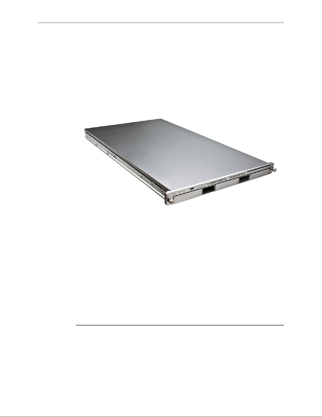
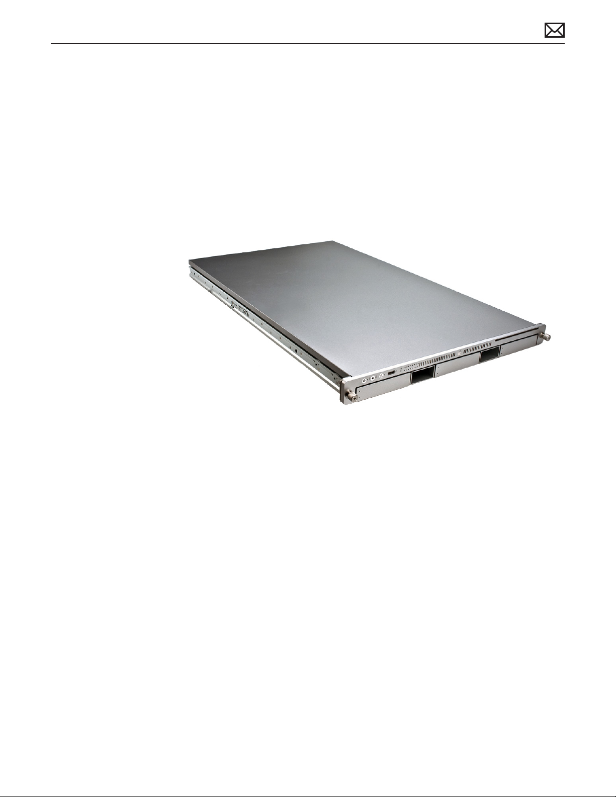
The Xserve (Early 2009) rack-optimized server features single or dual Quad-Core Intel Xeon
“Nehalem” processors, integrated memory controllers featuring up to 12 DIMMs of 1066MHz
DDR3 ECC RAM, three hot-plug drive bays supporting SATA or SAS Apple Drive Modules,
support for a Solid-State Drive (SSD) boot drive, dual x16 PCI Express 2.0 slots, NVIDIA GeForce
GT 120 graphics subsystem and integrated lights-out management.
Identifying Features
The main features and service dierences include:
• single and dual Intel Xeon “Nehalem” processors
• 6 or 12 DIMM slots depending on processor conguration
• Solid-State Drive Support
• Mini DisplayPort connector on rear panel
Xserve (Early 2009) Basics — Overview 9
Page 10
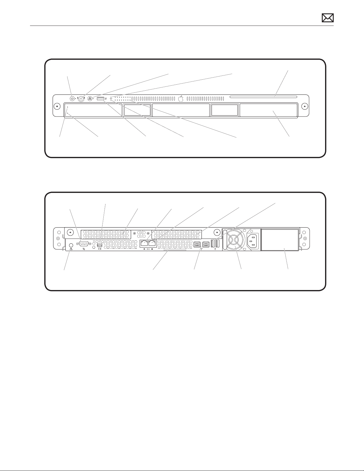
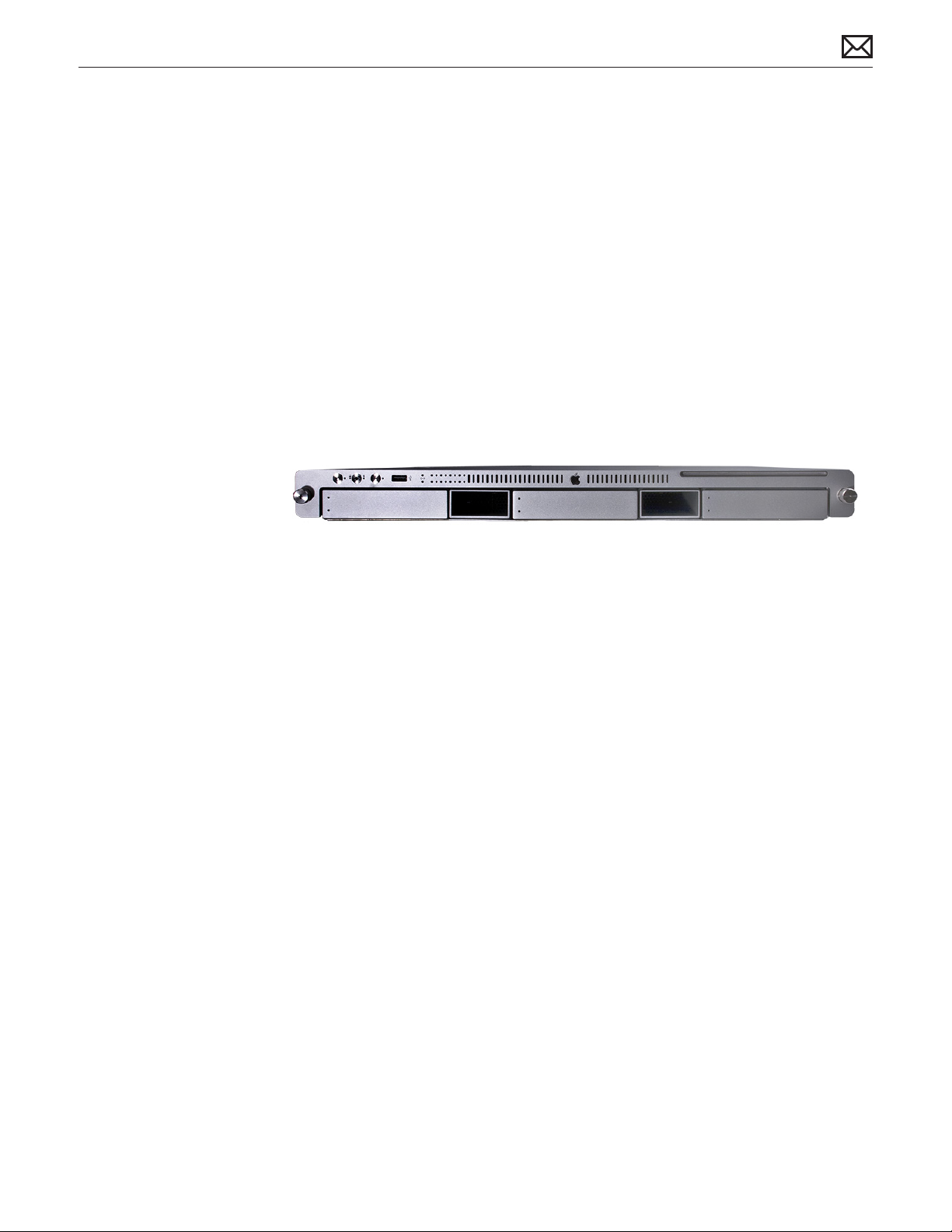
Front View
On/standby button
Drive module
status light
Rear View
Serial console
and light
port
Enclosure lock
and status light
Drive module
activity light
Mini DisplayPort
USB 2.0
Expansion
slot 2
port
System identifier
button/light
Ethernet link light
Ethernet
port 2
(Port 1)
Ethernet
port 1
Ethernet link light
(Port 2)
System activity
lights
Expansion
slot 1
Optical drive
Drive module
bays (3)
USB 2.0 ports (2)
2010-06-28
System identifier
button/light
System information tag
(pullout tab)
FireWire 800
ports (2)
Power supply
bay 1
Power supply
bay 2
Xserve (Early 2009) Basics — Overview 10
Page 11
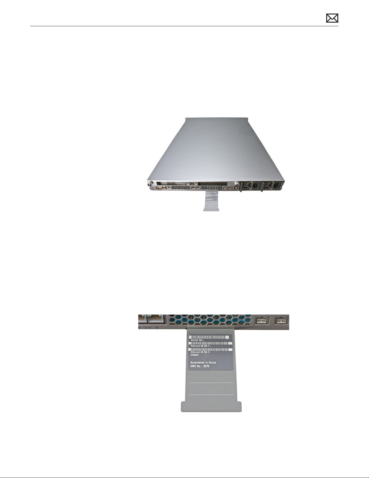
Serial Number Location
The serial number is located at the rear of the unit: on the ID Tab.
2010-06-28
Xserve (Early 2009) Basics — Overview 11
Page 12
Hot-Pluggable SATA or SAS Drives
The server includes three hard drive bays at the front of the Xserve. All bays support Apple
qualied hot-pluggable Apple Serial ATA (SATA) or Serial Attached SCSI (SAS) drive modules.
Xserve drive bays support qualied Apple Drive Modules with Apple qualied hard drives
and rmware only. Drive bays not congured with an Apple Drive Module ship with a nonfunctional blank drive carrier which do not support third-party hard drive installation.
Drive bays are numbered 1-3, beginning with the far left bay. The drive installed in bay 1 is the
boot drive and should have the operating system installed on it. Xserve’s congured with a
Solid-State Drive (SSD) will contain the Mac OS X Server operating system and function as the
boot drive.
You can replace or install hard drives while the Xserve is running; you do not need to
shutdown or open the Xserve rst, but you may need to dismount the drive from the Xserve
OS beforehand. A status light on the front of each drive indicates when it is safe to remove the
drive without losing data. For more information, see “Apple Drive Module” in the Take Apart
chapter.
Solid-State Drive
The server may include an optional Solid-State Drive. The drive contains the Mac OS X Server
operating system as the boot drive for the Xserve.
2010-06-28
Xserve (Early 2009) Basics — Overview 12
Page 13

Power Supply Redundancy
The Xserve (Early 2009) supports up to two power supply modules for redundancy. There are
two power supply bays in the rear of the enclosure. You can replace or install a power supply
from the back panel without removing the Xserve from the rack. If the Xserve has two power
supplies, they are hot-swappable; the Xserve will continue to operate using only one supply
while the second is removed. For more information about removing or installing power supply
modules, see “Power Supply” in the Take Apart chapter.
How to Identify Single- and Dual-Processor Congurations
To identify the conguration of an Xserve (Early 2009) computer, check the code on the
computer’s ID Tab, which is located on the computer’s back panel. See “Serial Number
Location.”
There are three options for identifying single and dual processor congurations:
• Quad-Core Xserve (Early 2009): Single processor logic board with 6DIMM slots, and one
large heat sink
• 8-Core Xserve (Early 2009): Dual processor logic board with 12 DIMM slots, and two large
heat sinks:
• Quad-Core Xserve (Early 2009): Single processor logic board, 12 DIMM slots and one large
heat sink. This option is present only when a single-processor logic board has previously
been replaced via the Xserve service parts kit.
2010-06-28
Xserve (Early 2009) Basics — Overview 13
Page 14

Apple Technician Guide
Troubleshooting
Xserve (Early 2009)
© 2009 Apple Inc. All rights reserved.
Page 15
General Troubleshooting
Update System Software
Important: Whenever possible before beginning troubleshooting, ensure the latest software
and rmware updates have been applied.
Troubleshooting Theory
For general information on troubleshooting theory, refer to:
http://service.info.apple.com/service_training/en/006/troubleshoot/index.php?page=intro
Emerging Issues
For the latest on troubleshooting issues, refer to:
http://support.apple.com/kb/index?page=search&q=khot%20Xserve%20Emerging%20
Issue
Hardware vs. Software
For information on how to isolate a hardware issue from a software issue, refer to:
http://support.apple.com/kb/TS1388
TS1394—Mac OS X: Troubleshooting installation and software updates <http://support.apple.
com/kb/TS1394>
HT2956—Troubleshooting Mac OS X installation from CD or DVD <http://support.apple.com/
kb/HT2956>
For information on how to troubleshoot a software issue, refer to:
HT1199—Mac OS X: How to troubleshoot a software issue <http://support.apple.com/kb/
HT1199>
HT1219—Xserve, Xserve RAID: Apple Drive Module (ADM) compatibility <http://support.apple.
com/kb/HT1219>
2010-06-28
Xserve (Early 2009) General Troubleshooting — Update System Software 15
Page 16

Xserve Firmware Updates
Firmware is the name given to software that is written into memory circuits, such as ash
memory, that will hold the software code indenitely, even when power is removed from the
hardware. Firmware on Intel Mac computers is designed to be updated if necessary through a
software update.
EFI and SMC rmware is stored on the Xserve (Early 2009) backplane board. EFI rmware
updates update the Boot ROM, and SMC updates update the System Management Controller
rmware. The SMC manages fans and other environmental parameters that are independent of
the Boot ROM.
Firmware symptoms can be easily mistaken for hardware issues (e.g., overheating issues, fan
noise issues, etc.). Always check both EFI and SMC rmware versions and update if necessary
before replacing any hardware components.
The following lists describe the type of symptoms that may be resolved by updating the EFI
and SMC rmware.
Symptoms that may be resolved by updating EFI rmware:
• Cannot eject media (various conditions)
• No video on start up
• Not waking or sleeping when expected
• Bad media taking too long to eject (including holding mouse button down at startup taking
minutes to eject)
Symptoms that may be resolved by updating SMC rmware:
• Fan related behavior (excessive speed or noise)
• Loud audible clicking from some fans
• Thermal shut down or warnings
• Diagnostics reporting failures
• Sleep/wake issues
• Intermittent shut down
• SMC causes bad/missing ambient sensor to cause the computer to go to sleep
• Hangs, black screen on restart from Windows
Please follow the steps outlined in KnowledgeBase article HT2013, “About Firmware Updates
for Xserve,” to perform an EFI and/or SMC rmware update. Information about rmware
versions for Intel Macs can be found in KnowledgeBase article HT1237, “Mac OS X: Firmware
Updates for Intel-based Macs.”
Memory Conguration
Xserve (Early 2009) comes with a minimum of 3 GB of 1066MHz DDR3 ECC memory, installed as
three 1 GB unbuered dual inline memory modules (UDIMMs).
2010-06-28
Xserve (Early 2009) General Troubleshooting — Xserve Firmware Updates 16
Page 17
DIMMs must t these specications:
• PC3-8500,1066 MHz, DDR3 SDRAM UDIMMs
• 72-bit wide, 240-pin modules
• 36 memory ICs maximum per UDIMM
• Error-correcting code (ECC)
For proper operation of Xserve (Early 2009) computers, Apple recommends using only Appleapproved DIMMs. Refer to GSX for Apple DIMM service part numbers. Memory from older
Xserve computers is not compatible with Xserve (Early 2009).
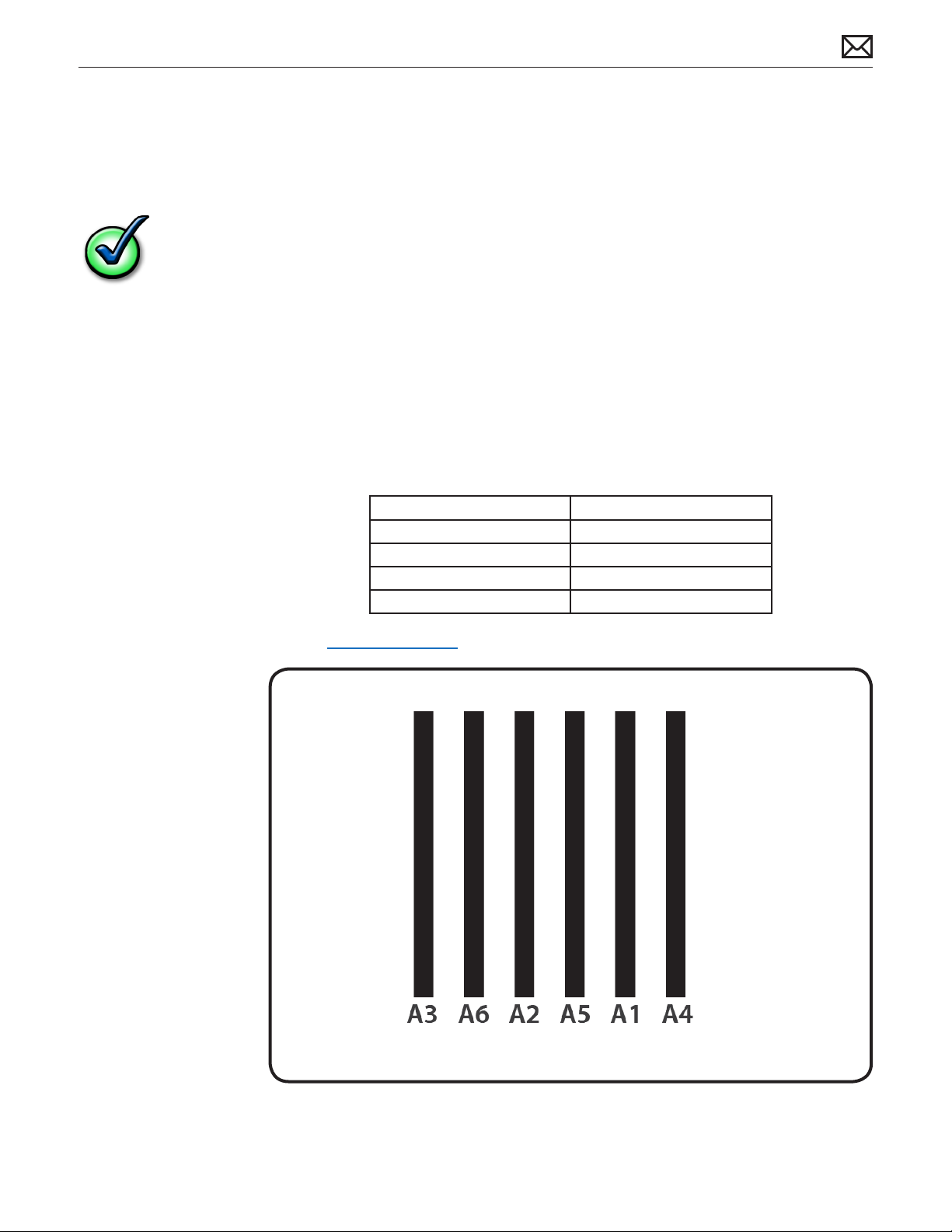
Single Processor
Single-processor (quad-core) computers have six memory slots. You can install 1 GB, 2 GB or
4GB DIMMs for a total of up to 24 GB of memory.
You can install dierent size DIMMs in Xserve (Early 2009). However, for best performance,
Apple recommends you install equal-size DIMMs (all 1, 2 or 4GB) lling the slots in the order
listed in this table.
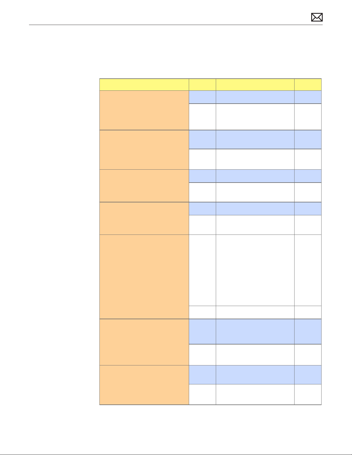
If you have Fill these slots
Three DIMMs A1, A2, and A3
Four DIMMs A1, A2, A3, and A4
Five DIMMs A1, A2, A3, A4, and A5
Six DIMMs A1, A2, A3, A4, A5, and A6
See also “Memory Slot Utility” below.
2010-06-28
Xserve (Early 2009) General Troubleshooting — Memory Conguration 17
Page 18
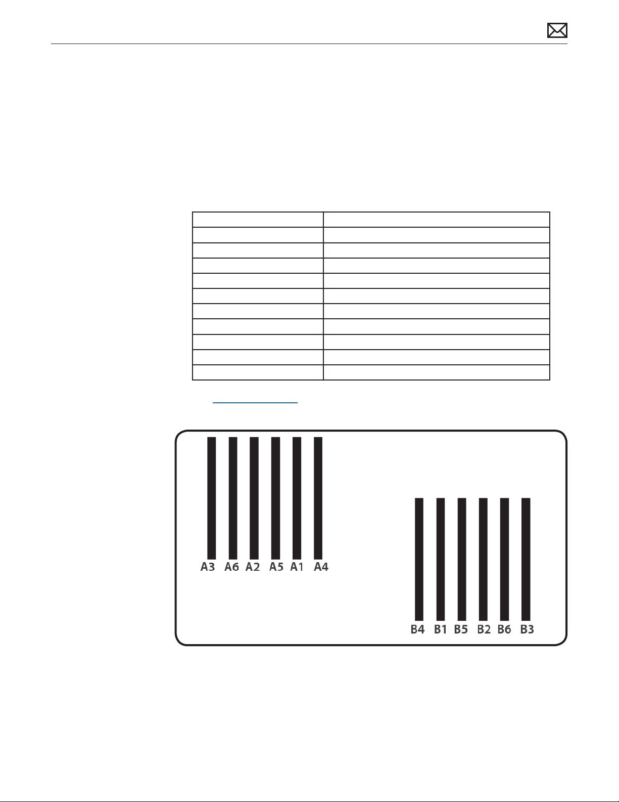
Dual Processor
Dual-processor (eight-core) computers have twelve memory slots. You can install 1 GB, 2 GB, or
4 GB DIMMs for a total of up to 48 GB of memory.
You can install dierent size DIMMs. in Xserve (Early 2009) However, for best performance, Apple
recommends you install equal-size DIMMs (all 1, 2, or 4 GB) lling the slots in the order listed in
this table.
If you have Fill in these slots
Three DIMMs A1, A2, and A3
Four DIMMs A1, A2, and B1, B2
Five DIMMs A1, A2, A3 and B1, B2
Six DIMMs A1, A2, A3 and B1, B2, B3
Seven DIMMs A1, A2, A3, A4 and B1, B2, B3
Eight DIMMs A1, A2, A3, A4 and B1, B2, B3, B4
Nine DIMMs A1, A2, A3, A4, A5 and B1, B2, B3, B4
Ten DIMMs A1, A2, A3, A4, A5, A6 and B1, B2, B3, B4
Eleven DIMMs A1, A2, A3, A4, A5, A6 and B1, B2, B3, B4, B5
Twelve DIMMs A1, A2, A3, A4, A5, A6 and B1, B2, B3, B4, B5, B6
See also “Memory Slot Utility” below.
2010-06-28
Xserve (Early 2009) General Troubleshooting — Memory Conguration 18
Page 19
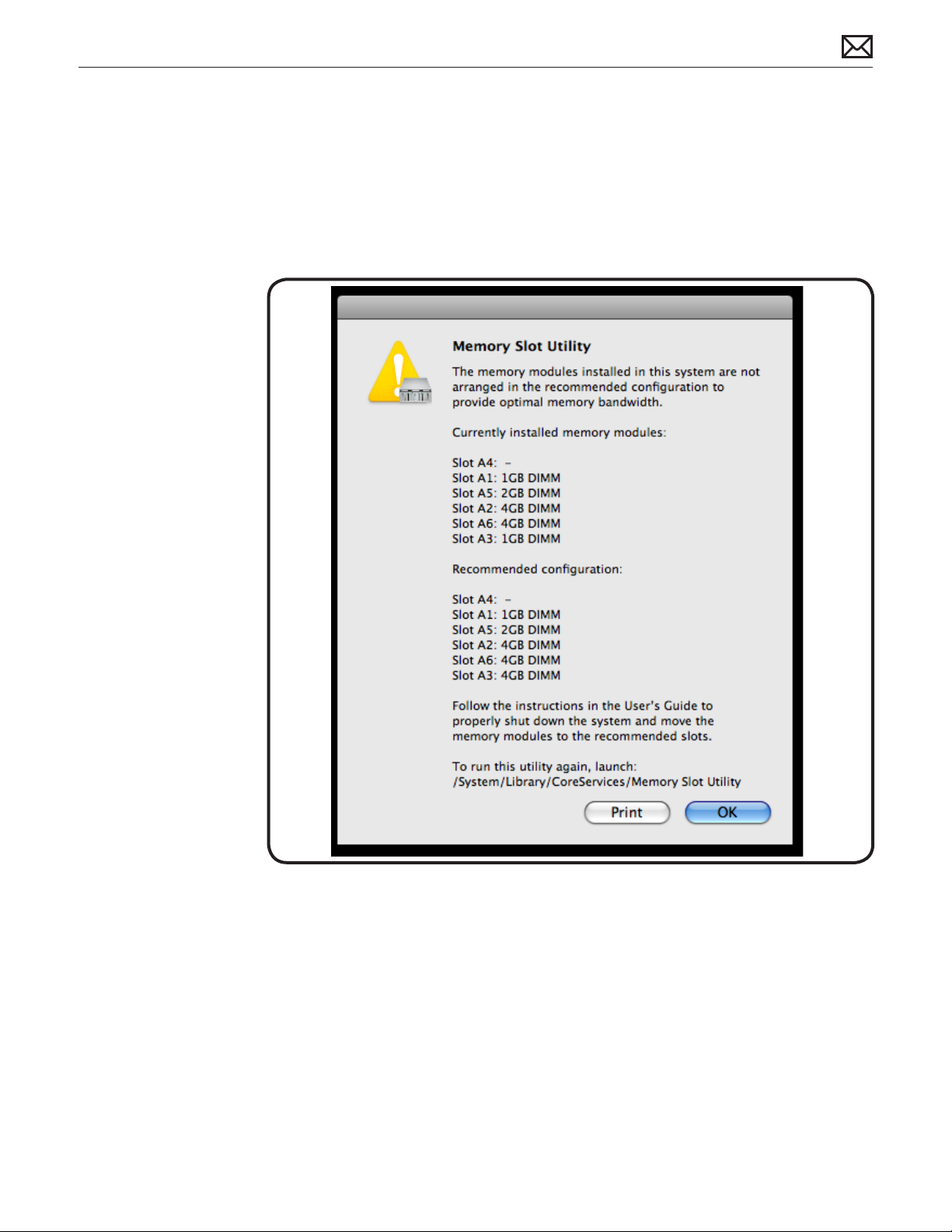
Memory Slot Utility
If you install dierent size DIMMs in single-processor or dual-processor computers, follow the
order in the tables above. If the DIMM conguration you install doesn’t provide optimized
performance, the Memory Slot Utility will appear on screen and recommend an improved
conguration. To use the Memory Slot Utility again, go to /System/Library/Core Services.
Example of Memory Slot Utility Screen for Single-Processor Computer
2010-06-28
Xserve (Early 2009) General Troubleshooting — Memory Conguration 19
Page 20
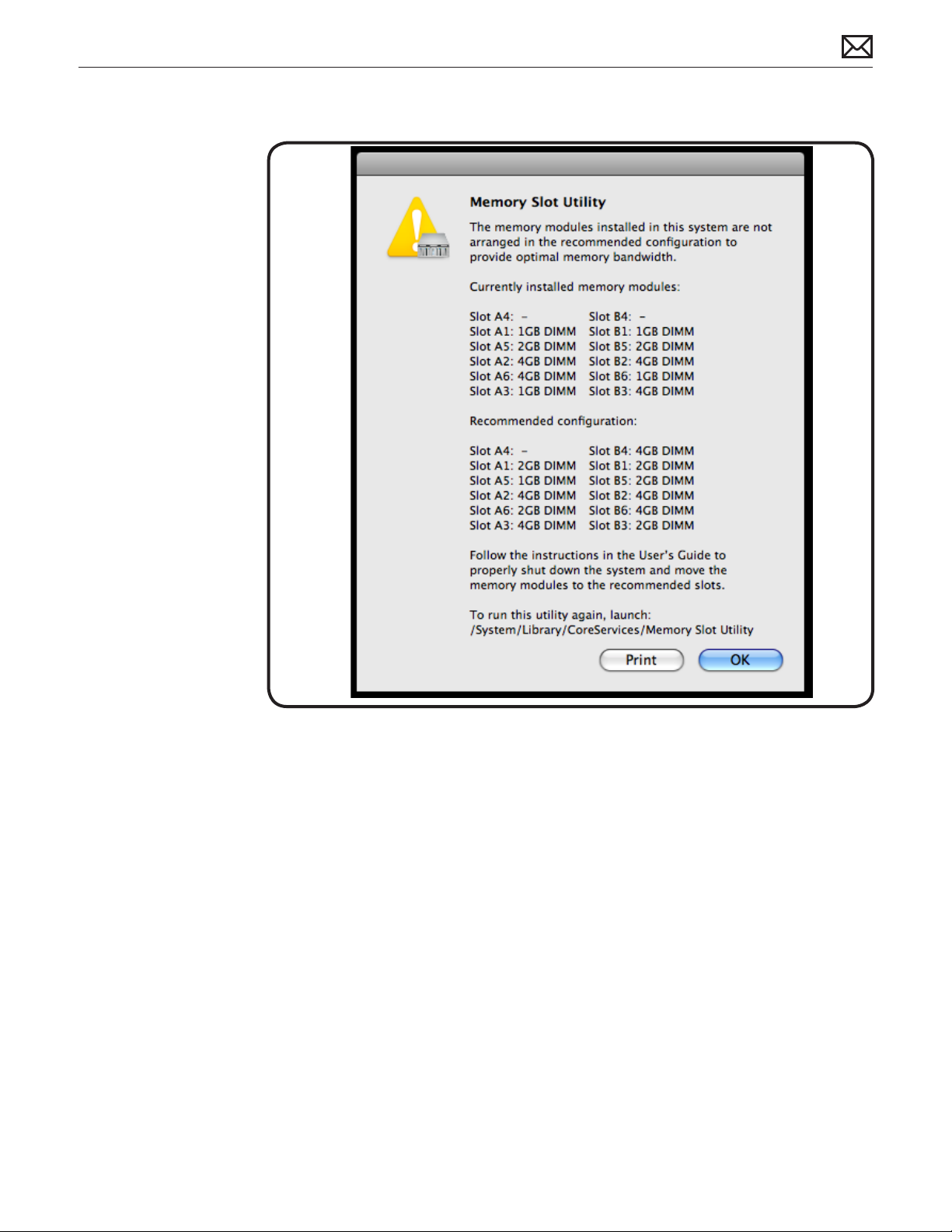
Example of Memory Slot Utility Screen for Dual-Processor Computer
2010-06-28
Xserve (Early 2009) General Troubleshooting — Memory Conguration 20
Page 21
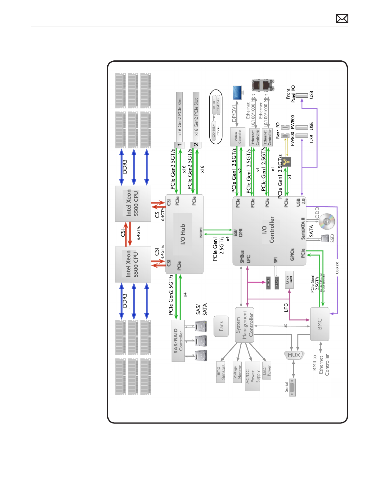
Block Diagram
2010-06-28
Xserve (Early 2009) General Troubleshooting — Block Diagram 21
Page 22
Diagnostic LEDs
Logic Board Diagnostic LEDs
The Xserve (Early 2009) logic board includes a set of LEDs to help service providers
troubleshoot the computer. The LEDs are located on the logic board below the DIMM
connectors, at the rear of the unit, to the left side of the unit (looking from the back), and on
the Drive Interconnect Backplane or Xserve RAID Card.
Some tips:
• You must remove the unit from its rack and place it on a sold surface with its cover removed
in order to view these LEDs. Most internal diagnostic LEDs are only enabled to come on when
the cover is removed (memory DIMM LEDs remain ON even with the cover in place).
• Do not attempt to troubleshoot the unit solely by these LEDs alone. Use this information to
guide your troubleshooting, not lead it.
If a specic error condition exists, there should be corresponding LED evidence to help verify
and isolate the issue. However, it is not possible to deduce a fault or isolate a specic symptom
solely by examining these LEDs out of context.
2010-06-28
Xserve (Early 2009) General Troubleshooting — Diagnostic LEDs 22
Page 23
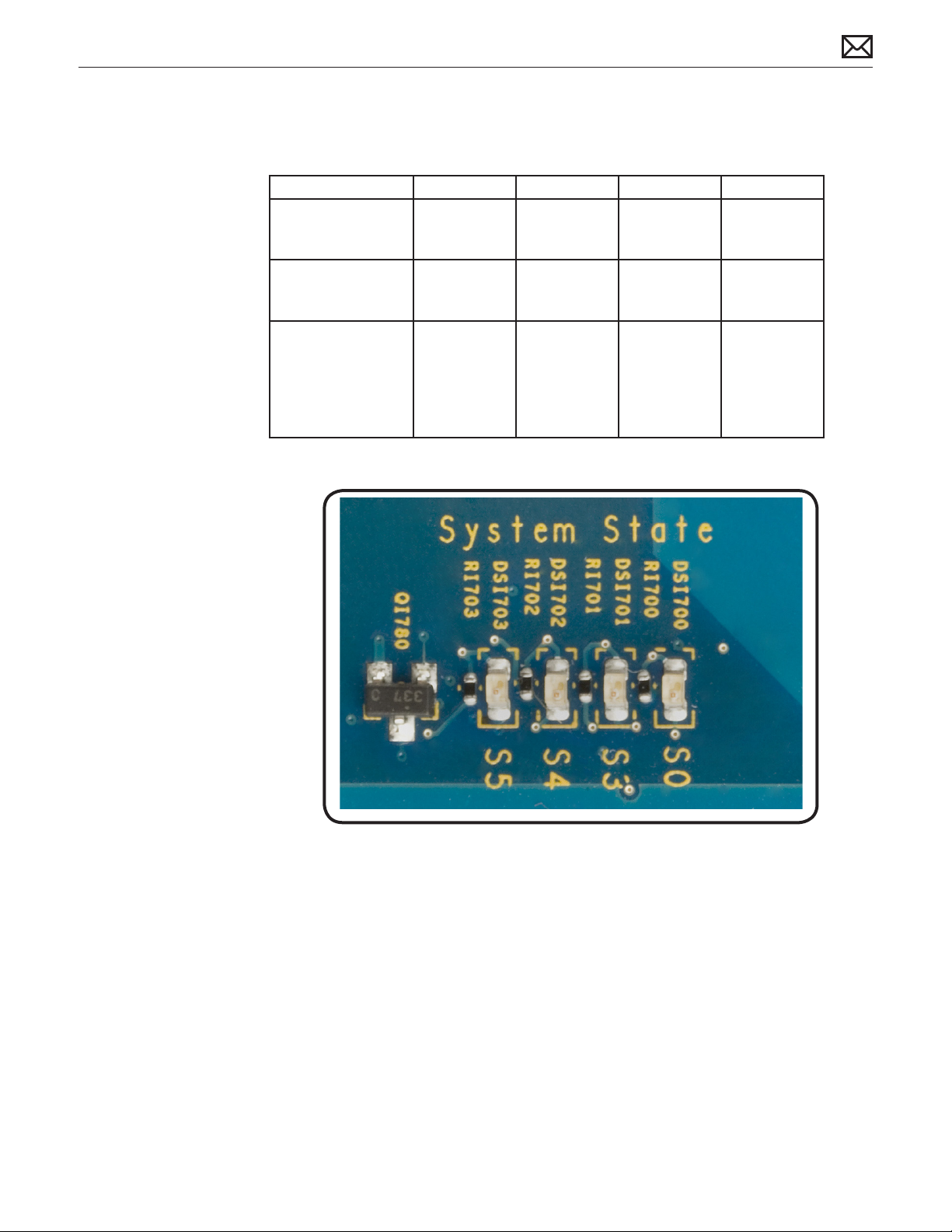
1. System State LEDs
Use the following table to interpret the LEDs.
Location Name Color Nominal Indicates
S0 Power ON Green On; o when
in standby
mode
S3 Sleep Green O, on when
Xserve is in
sleep mode
S5 Standby Green O; on when
Xserve is in
standby
System is
running
System is in
sleep mode
Standby
mode,
illuminates
when AC
power is
attached
2010-06-28
Xserve (Early 2009) General Troubleshooting — Diagnostic LEDs 23
Page 24
2. CPU Error LEDs
Use the following table to interpret the LEDs.
Location Color Nominal Indicates
CPU_PWRGD Green O; on to indicate
hardware power has
passed
RSM_RST Yellow, Red O Fault preventing CPU from
SYS_PWRGD Green On at power-on to
indicate power has
passed
PLT_RST Red O; on Yellow at
power on
CPU B OVERTEMP Red O; on if CPU B core
exceeds normal
temperature
IOH OVERTEMP Red O; on if IOH exceeds
normal temperature
CPU A OVERTEMP Red O; on if CPU A core
exceeds normal
temperature
Power chain in hardware
executing instructions
Power chain in hardware
Platform reset
Temperature of CPU B core
status
Temperature of IOH status
Temperature of CPU A core
status
MXM OVERTEMP Red O; on if MXM video
card exceeds normal
temperature
Temperature of MXM video
card status
2010-06-28
Xserve (Early 2009) General Troubleshooting — Diagnostic LEDs 24
Page 25

Platform Reset
Normally remains on during standby. This LED ashes on (yellow) briey at power-on. LED
should turn o as system powers up and begins to execute instructions.
Overtemp LEDs
Normally o. These LEDs come on if an error occurs.
If LED is solidly on, it may indicate a processor over-temperature condition. Initial processor
over-temperature can cause symptoms such as sluggish computer performance. Chronic
processor over-temperature can cause the computer to hang completely.
Troubleshooting:
• Verify proper heatsink installation.
• Verify all fans are operating properly, especially the fan array.
• If both overtemp LEDs come on immediately when the computer is turned on, a faulty
power supply could be one cause of this behavior. Replace power supply.
• Try swapping CPU A and CPU B locations. If the CPU Error LED follows the CPU, replace that
CPU.
3. EFI POST (Power On Self Test) LEDs
This group of eight LEDs are arranged into two sets of four LEDs, representing a binary code
that only has any signicance during the short time between power-on and the unit begins to
boot the OS, while the CPU is executing EFI code only. At no other time should these LEDs be
used or interpreted to mean anything meaningful.
The code is more easily described as two Hexadecimal digits ranging from $00 to $FF, to make
it easier to list and compare during troubleshooting. Each ONE represents an LED that is ON,
and each ZERO represents an LED that is OFF
Normal power-up LED sequence:
• The sequence of codes below is typical in the rst few seconds of a functioning unit’s boot
cycle, immediately following power-on, during the EFI phase of startup.
• If your system is not booting you should check these LEDs closely to verify the sequence of
codes has been executed in addition to your normal troubleshooting steps. Each code will only
remain ON GREEN for a split-second each. The entire sequence takes only a few seconds to
progress through.
• To see this sequence, power-on the unit (use the remote power on/o button on the logic
board) while holding down the option key on an attached USB keyboard, to invoke the EFI
startup manager and prevent the unit from leaving EFI and booting into any OS. Do this as you
watch these LEDs as they progress through the following sequence:
2010-06-28
Begin (power-on)
Xserve (Early 2009) General Troubleshooting — Diagnostic LEDs 25
Page 26
$Bx = 1 0 1 1 X X X X = All $Bx codes below are memory init codes (x may be any code 0 - F)
$BF = 1 0 0 1 1 1 1 1 = If the unit does not progress past any $Bx memory init codes, this could
indicate a memory issue regardless of whether DIMM diagnostic error LEDs are ON or not.
$12 = 0 0 0 1 0 0 1 0 = After memory initialization has successfully completed
$51 = 0 1 0 1 0 0 0 1 = Video driver enabled beyond this point. Attached display should be
displaying an image now. If not, this may indicate a graphics card issue.
$F9 = 1 1 1 1 1 0 0 1 = EFI nished and passed on control to OS boot loader
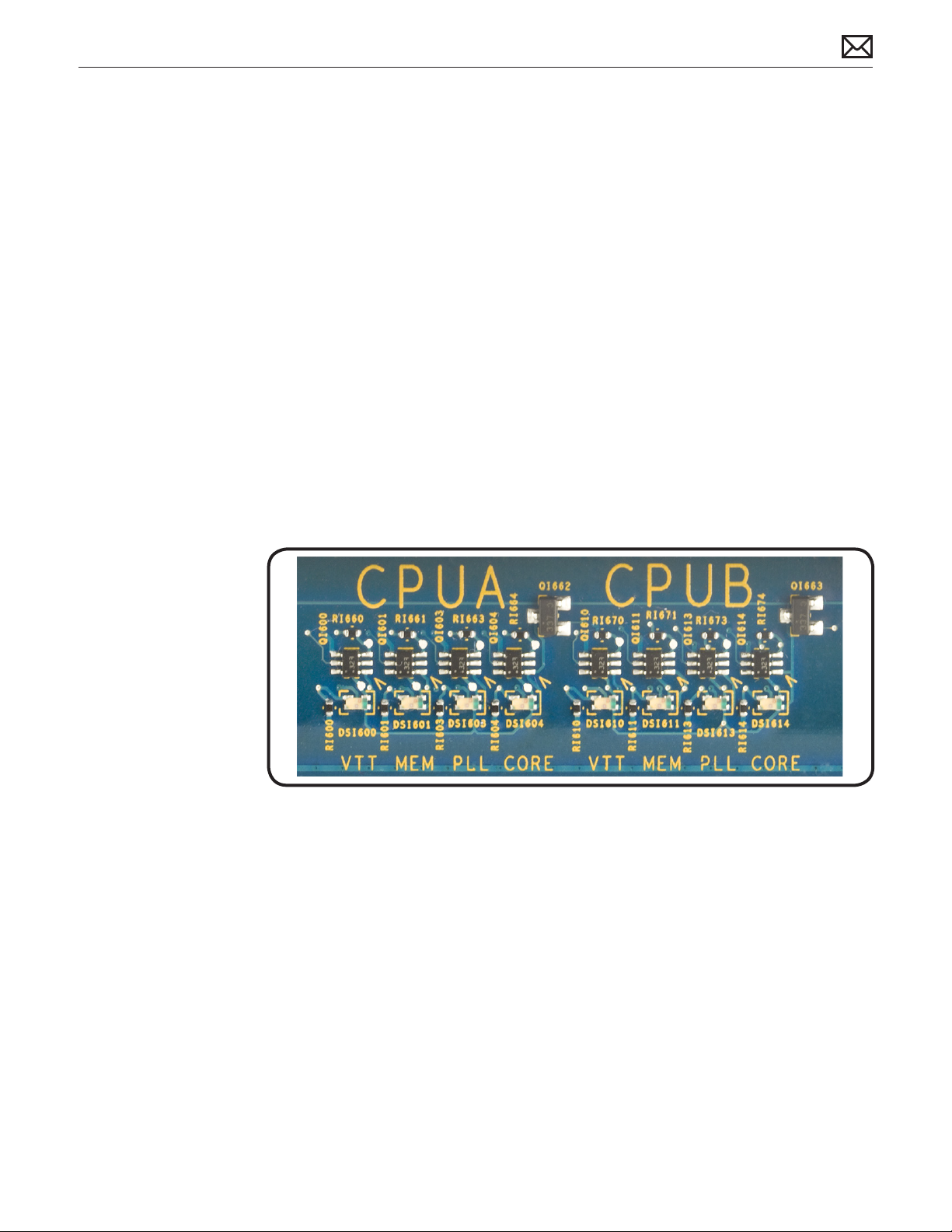
4. CPU Voltage LEDs
This group of LEDs will normally FLASH RED briey during power-on, then should normally
remain ON solidly GREEN when all voltage regulators are functioning properly to provide
voltages to CPU A and CPU B, as well as IOH.
If any of these LEDs remain ON RED, this indicates that the corresponding voltage regulator is
enabled but not providing any voltage output.
2010-06-28
In single processor units the LED group for the second processor are not present.
Xserve (Early 2009) General Troubleshooting — Diagnostic LEDs 26
Page 27
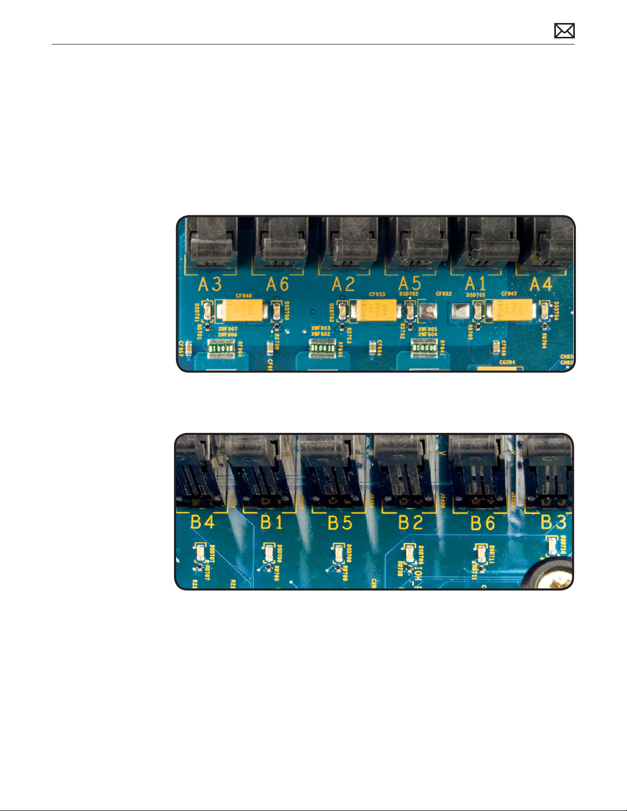
5 & 6. Memory Diagnostic LEDs (A1 - A6 and B1 - B6)
This group of LEDs will normally remain OFF during power-on and throughout normal
operation. If any of these LEDs come ON RED, this indicates that the corresponding DIMM (or
its slot) may be faulty. To verify whether the fault lies with the DIMM or the slot, power down
the unit and move the DIMM to another slot. If the DIMM is faulty, the LED adjacent to its new
slot should come ON RED when power is reapplied. If a known-good DIMM is installed in the
suspect slot and the LED adjacent to this slot should come ON RED , this may indicate a faulty
DIMM slot on the logic board.
2010-06-28
How to Troubleshoot Memory LEDs
1. Remove and reseat DIMM
2. Restart computer. If associated LED is no longer illuminated, issue is resolved
3. If associated LED remains illuminated, replace DIMM with new DIMM
4. Restart computer and verify LED is no longer illuminated
Xserve (Early 2009) General Troubleshooting — Diagnostic LEDs 27
Page 28

7. Reset Buttons
System Management Controller (SMC) Reset
The System Management Controller (SMC) is a chip on the logic board that controls all power
functions for the Xserve. If the Xserve is experiencing any power issue, resetting the SMC may
resolve it. The SMC controls several functions, including:
• Telling the Xserve when to turn on, turn o, sleep, wake, idle, and so forth
• Handling system resets from various commands
• Controlling the fans
It is also recommended that the SMC be reset on any new logic board after it is installed as part
of a repair.
Note that resetting the SMC does not reset the PRAM. Resetting the SMC will not resolve issues
in which the Xserve is unresponsive—in these situations, restarting the Xserve will generally
suce.
If the Xserve isn’t responding, perform these steps one at a time, in the following order, until
the issue has been resolved:
1. Force Quit (Option-Command-Escape)
2. Restart (Control-Command-Power)
3. Force Shut Down (press the power button for 10 seconds)
4. Remove the Xserve from the rack (if applicable)
5. Remove the Top Case
6. Press the SMC Reset button on the logic board
Resetting the SMC can resolve some Xserve issues such as not starting up, not displaying video,
sleep issues, fan noise issues, and so forth. If the Xserve still exhibits these types of issues after
you’ve restarted the Xserve, try resetting the SMC. There are two ways to reset the SMC on the
Xserve.
System Management Control (SMC) Reset in Rack
1. Shut Down the Xserve, either locally or using remote commands (or if the Xserve is not
responding, hold the power button until it turns o).
2. Unplug the AC power cord.
2010-06-28
3. Wait at least 15 seconds.
4. Plug the power cord back in, making sure the power button is not being pressed at the time.
Xserve (Early 2009) General Troubleshooting — Diagnostic LEDs 28
Page 29
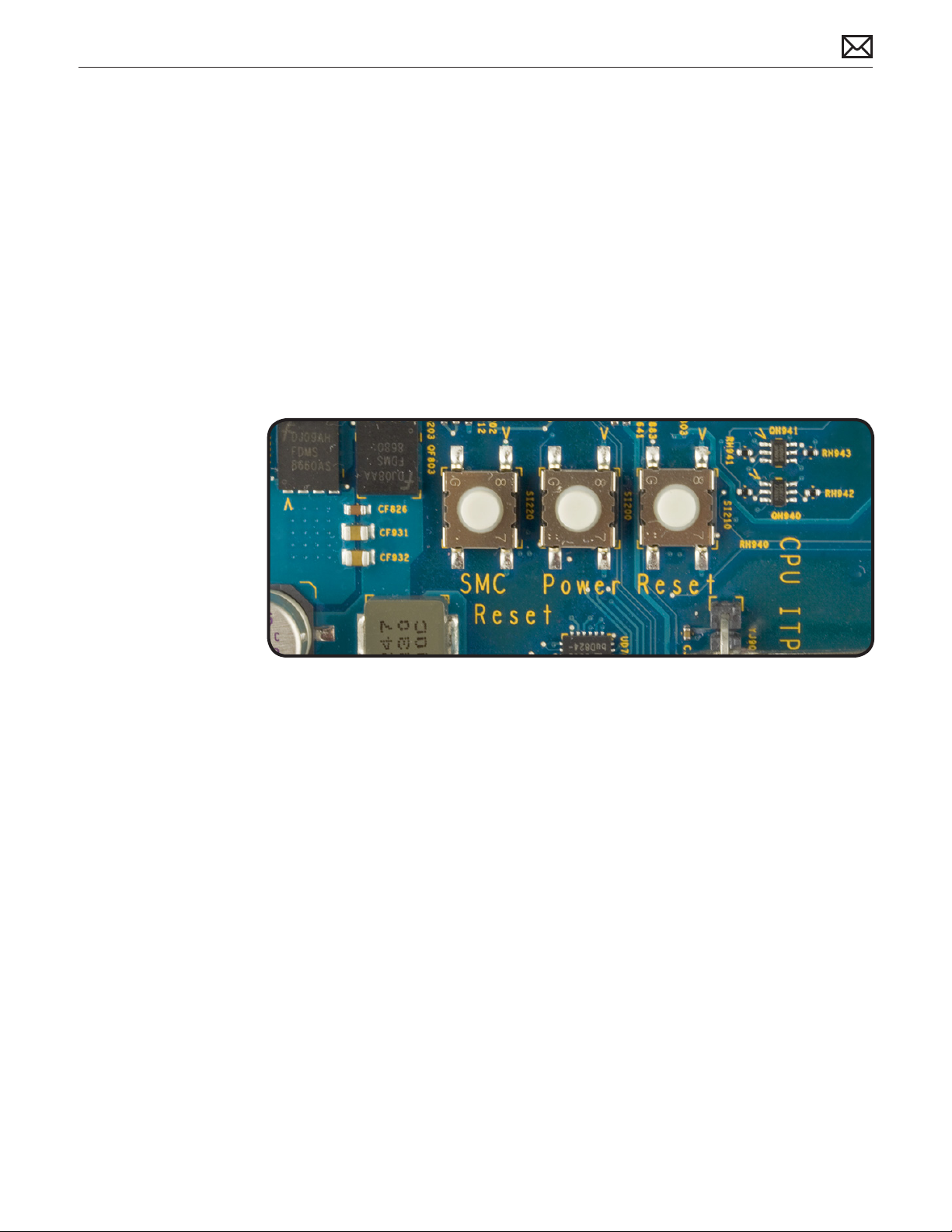
5. Press the power button to start up the Xserve.
Power ON / OFF Button
Behaves exactly like the front panel power button, and can be used as an alternate way to turn
the unit on and o if needed.
Reset Buttons
When pressed, resets CPUs regardless of what is currently running. This reset overrides all
software processes and restarts the system. Use with caution as this form of reset may corrupt
software or les on a drive.
2010-06-28
Drive Interconnect Backplane LEDs
Note: The following information describes the diagnostic LEDs present on the interconnect
backplane.
This group of eight LEDs are arranged into two sets of four LEDs, representing information
about the SATA / SAS communication between the drive controller channels on the drive
interconnect backplane and the drive modules themselves. The optional SSD drive does not
have a representative LED on this board.
There is also a ‘heartbeat’ LED on this board which starts ashing ON GREEN and OFF when EFI
loads immediately after power-on and continues to ash ON and OFF during normal operation.
The rst group of four LEDs indicates activity for the four I/O channels corresponding to the
three drive bays. Since there are only three drive bays, the fourth I/O channel and LED are not
used and should remain OFF during normal operation.
The second group of four LEDs indicates that the controller has recognized that a drive
module is present and connected. These LEDs are normally solidly ON GREEN when no drive
is present, and turn OFF when a drive module has been inserted into the corresponding drive
Xserve (Early 2009) General Troubleshooting — Diagnostic LEDs 29
Page 30

bay and the controller has recognized this event. The LED will turn ON GREEN again when the
corresponding drive module has been removed from its bay.
Since there are only three drive bays, the fourth I/O channel and LED are not used and should
remain ON GREEN during normal operation.
When you power-on the system, you should see the following activity sequence on these LEDs:
1. The entire group of eight LEDs should come ON solid GREEN when power is applied and
remain on for a few seconds.
2. The heartbeat LED begins ashing when EFI loads in the rst few second after power-on.
The rst group of four activity LEDs should now turn OFF. The second group of four ‘drive
present’ LEDs should remain on for a few more seconds.
3. The second group of four ‘drive present’ LEDs should each turn OFF as the controller scans
and recognizes each connected drive module in turn, from bay 1 to bay 3 in order. The
fourth LED should remain ON since no drive is present on the fourth I/O channel.
4. Beyond this point, the only LEDs that should be ashing are among the rst group of four
drive activity LEDs, to indicate drive activity between a corresponding drive module, such
as the boot drive module booting the OS, and the drive controller.
2010-06-28
Xserve (Early 2009) General Troubleshooting — Diagnostic LEDs 30
Page 31

Symptom Charts
Follow the steps in the order indicated below. If an action resolves the issue, retest the system
to verify. If the issue persists after retesting, return to step 1.
Startup and Power Issues
No Power / Dead Unit
Unlikely cause: Optical drive, hard drive(s), fan array, memory, RAID battery
Quick Check
Symptom Quick Check
No Power / Dead Unit
• No fan or drive module spin
• No LED activity
1. Check the front panel on/standby light. This
light should be solid white when the Xserve is
running, and o when the Xserve is in standby
mode. If it’s ashing white, the Xserve is in sleep
mode.
2. Verify the power outlet and power cord are
known good and that AC power is present.
3. Check the power supply status light next to the
power cord connector on the rear of the Xserve
(check the LEDs for both supplies in a twopower-supply conguration).
4. Solid green indicates power is available and
Xserve should be on.
5. Blinking green indicates AC power is available
but power to the Xserve components from this
supply is on standby (usually because the Xserve
is turned o).
6. Red indicates either no AC power is available to
this supply from the power cord or this power
supply has failed.
7. Disconnect all external cables such as network,
peripheral, and expansion card connections, and
press the power button again.
2010-06-28
Xserve (Early 2009) Symptom Charts 31
Page 32

Deep Dive
Check Result Action Code
1. Press the SMC Reset button
on the logic board to reset the
SMC. Verify that the Xserve
powers on
2. Check internal diagnostic LEDs.
Go to diagnostic LED section
for more information. Verify
that the Xserve powers on.
3. Remove all three drive
modules and press the power
button. Verify that the Xserve
powers on.
4. Reconnect each one at a time,
verifying unit operation as
drive module is reinstalled.
Verify that the Xserve powers
on.
5. Remove both internal PCI
riser cards and any installed
expansion cards and press the
power button. Verify that the
Xserve powers on.
Yes Issue resolved.
No Go to Step 2
Yes Issue resolved.
No Go to Step 3
Yes Suspect drive module(s) as
cause. Go to Step 4
No Go to Step 5
Yes Repeat Step 4 until the drive
module is isolated.
No Failed drive module. Replace
drive module. Issue resolved.
Yes Suspect PCI card(s) and/or
riser card(s) as cause. Go to
Step 6
No Go to Step 7
H02
6. Reconnect each one at a time,
verifying unit operation as card
is reinstalled. Verify that the
Xserve powers on.
7. Verify that the power supply
is properly connected to the
power distribution board.
8. Verify the front panel board
cable is properly connected at
both ends.
9. Reseat the front panel board.
Verify that the Xserve powers
on.
Yes Repeat Step 6 until the card is
isolated.
No Failed card. Replace card.
Issue resolved.
Yes Go to Step 8
No Ensure power supply is
properly connected to the
power distribution board. Go
to step 8
Yes Go to Step 9
No Ensure the front panel board
cable is properly connected at
both ends. Go to step 9
Yes Issue resolved.
No Go to Step 10
M17
2010-06-28
Xserve (Early 2009) Symptom Charts 32
Page 33

10. Verify all cable connections
to the logic board and drive
interconnect backplane are
secure.
Yes Go to Step 11
No Ensure all cable connections
to the logic board and drive
interconnect backplane are
secure. Go to Step 11
11. Replace the power supply.
Verify that the Xserve powers
on.
12. Replace the power distribution
board. Verify that the Xserve
powers on.
13. Replace the front panel board
cable. Verify that the Xserve
powers on.
14. Replace the front panel board.
Verify that the Xserve powers
on.
15. Replace the drive interconnect
backplane. Verify that the
Xserve powers on.
16. Reseat both processors. Verify
that the Xserve powers on.
Yes Issue resolved. P01
No Go to Step 12
Yes Issue resolved. M01
No Go to Step 13
Yes Issue resolved. X03
No Go to Step 14
Yes Issue resolved. M01
No Go to Step 15
Yes Issue resolved. M01
No Go to Step 16
Yes Issue resolved.
No Go to Step 17
2010-06-28
17. Replace both processors. Verify
that the Xserve powers on.
Xserve (Early 2009) Symptom Charts — Startup and Power Issues 33
Yes Issue resolved. M08
No Reinstall original processors.
M08
Replace the logic board.
Page 34

Burnt Smell or Odor
Quick Check
Symptom Quick Check
Burnt Smell / Odor
• System emits an odor or smell
of smoke.
1. Disconnect the power cord from the system.
2. Identify the source of the odor.
3. Some odors may be present when operating
normally. Refer to http://support.apple.com/kb/
TA22044.
Some visual clues may include brown marks on PCBs,
and component damage i.e. transistors, ICs, inductors,
capacitors, resistors etc.
When certain components fail because of
overheating the smell or odor clues may not be
evident after the time of the incident.
Some components may not be easily accessible for
visual identication of possible failure.
Important Note: Components may emit a brief noncontinuous smoke or odor when the failure occurs.
However this does not typically suggest a safety
issue, however a thorough inspection should be
made. During inspection you feel there may a safety
issue with the System please notify Apple through
the appropriate escalation routes.
2010-06-28
Xserve (Early 2009) Symptom Charts — Startup and Power Issues 34
Page 35

Deep Dive
Check Result Action Code
1. Verify source of the odor ie
foreign contaminant such as
uid ingress, dust, hair etc
2. Inspect PCB’s and components
for indications of a thermal
event
3. Verify System is functioning
correctly
Yes Cleanup foreign contaminant,
replace any aected modules.
Foreign contaminants are not
covered by Apple warranties
No Go to step 2
Yes Replace any aected modules P08
No Go to step 3
Yes Some odors may be present
when operating normally.
Refer to http://support.
apple.com/kb/TA22044
No Please refer to best related
troubleshooting section.
P08
2010-06-28
Xserve (Early 2009) Symptom Charts — Startup and Power Issues 35
Page 36

Won’t Start Up / No Video/ LED On
Unlikely cause: Fan array, front panel board, memory, optical drive, power distribution board,
power supply, RAID battery
Quick Check
Symptom Quick Check
Won’t Startup / No Video / LED
On
• Xserve begins to power up but
does not boot
• Fan array and hard drive are
spinning
• Power LED is illuminated
• No activity lights
• No video on connected
external display
1. Conrm the system conguration supports
an external display. Not all congurations do,
although the mini DisplayPort connector on the
rear of the unit is present regardless.
2. Verify that the rear System Identier button
on the back of the logic board aligns with the
opening in the chassis back panel. If it does not,
realign the logic board.
3. Conrm at least one known good and
compatible memory DIMM is installed in the
system.
4. After power-on, verify front panel power light is
solidly on, and not ashing any error sequences
indicating a memory failure.
5. Connect known-good external bootable device,
keyboard, and mouse, then press Option key
during startup and select external startup device
to bring up system for diagnostics. Run complete
AXD diagnostics.
Deep Dive
Check Result Action Code
1. Press the SMC Reset button
on the logic board to reset
the SMC. Verify Xserve boots
from known good external
bootable device
2. Check internal diagnostic LEDs.
Go to diagnostic LED section
for more information. Verify
Xserve boots from known
good external bootable device.
3. Remove all three drive
modules and press the power
button. Verify Xserve boots
from known good external
bootable device.
Yes Issue resolved.
No Go to Step 2
Yes Issue resolved.
No Go to Step 3
Yes Suspect drive module(s) as
cause. Go to Step 4
No Go to Step 5
2010-06-28
Xserve (Early 2009) Symptom Charts — Startup and Power Issues 36
Page 37
4. Reconnect each one at a time,
verifying unit operation as
drive module is reinstalled.
Verify Xserve boots from
known good external bootable
device.
Yes Repeat Step 4 until the drive
module is isolated.
No Failed drive module. Replace
drive module. Issue resolved.
H02
5. Remove both internal PCI
riser cards and any installed
expansion cards and press the
power button. Verify Xserve
boots from known good
external bootable device.
6. Reconnect each one at a time,
verifying unit operation as
card is reinstalled. Verify Xserve
boots from known good
external bootable device.
7. Disconnect backplane-to-logic
board cable. Verify Xserve
boots from known good
external bootable device.
8. Replace drive interconnect
backplane. Reconnect
backplane-to-logic board
cable. Verify Xserve boots from
known good external bootable
device.
Yes Suspect PCI card(s) and/or
riser card(s) as cause. Go to
Step 6
No Go to Step 7
Yes Repeat Step 6 until the card is
isolated.
No Failed card. Replace card.
M17
Issue resolved.
Yes Go to Step 8
No Go to Step 9
Yes Issue resolved. M01
No Reinstall original drive
interconnect backplane. Go to
Step 9
2010-06-28
9. Replace backplane-to-logic
board cable. Verify Xserve
boots from known good
external bootable device.
10. Reseat both processors. Verify
Xserve boots from known
good external bootable device.
11. Replace both processors. Verify
Xserve boots from known
good external bootable device.
12. Replace logic board Verify
Xserve boots from known
good external bootable device.
Xserve (Early 2009) Symptom Charts — Startup and Power Issues 37
Yes Issue resolved. X03
No Go to Step 10
Yes Issue resolved. Go to Step 13
No Go to Step 11
Yes Issue resolved. Go to Step 13 M02
No Reinstall original processors.
Go to Step 12
Yes Issue resolved. Go to Step 13 M02
No Multiple module failure.
Return to step 7.
Page 38

13. Reinstall user’s original startup
drive module. Verify Xserve
boots from user’s original
startup drive module.
Yes Issue resolved.
No Replace user’s original startup
drive module. Start up
from Server Install Disc and
install server OS onto user’s
replacement startup drive
module. Verify Xserve boots
from replacement startup
drive module. Issue resolved.
Won’t Start Up / No Video/ Activity LEDs Flashing
Quick Check
Symptom Quick Check
H02
Won’t Boot / No Video / Activity
LEDs Flashing In Sequence
• Xserve begins to power up but
does not boot
• Fan array and hard drive are
spinning
• Power LED is illuminated
• Top row of activity lights ash
in sequence left to right and
then right to left
• No video on external display
1. Press the System Identier button a few times. If
the bottom row of activity lights illuminate from
right to left each time you press this button, then
it’s likely that the System Identier light is stuck
in on either the front or rear panel.
2. Verify that the rear System Identier button
on the back of the logic board aligns with the
opening in the chassis back panel. Also check
the front panel System Identier button. If either
button appears to be stuck in, follow the steps in
the deep-dive section of this symptom.
3. Connect known-good external bootable device,
keyboard, and mouse, then press Option key
during startup and select external startup
device to bring up system for diagnostics. Run
complete AXD diagnostics.
Deep Dive
Check Result Action Code
2010-06-28
1. Remove the front bezel and
make sure the front System
Identier button is not stuck.
Reseat the button if necessary.
Verify Xserve boots from
user’s original startup drive
module.
Xserve (Early 2009) Symptom Charts — Startup and Power Issues 38
Yes Issue resolved.
No Go to Step 2
Page 39

2. Reseat the front panel board
and its cable connectors.
Verify Xserve boots from user’s
original startup drive module.
Yes Issue resolved.
No Go to Step 3
3. Replace front panel board.
Verify Xserve boots from user’s
original startup drive module.
4. Reinstall original front panel
board. Remove and re-seat
logic board to enure rear panel
System Identier button is not
stuck in. Verify Xserve boots
from user’s original startup
drive module.
Yes Issue resolved. M02
No Go to Step 4
Yes Issue resolved.
No Replace logic board. M02
Intermittent Shutdown
Unlikely cause: hard drive, optical drive
Quick Check
Symptom Quick Check
Shutdown After Startup
• System shuts down almost
immediately after startup
1. Make sure the power cord is plugged in rmly.
2. Check that the power source is turned on and
the correct voltage is present.
2010-06-28
Intermittent Shutdown
• System shuts down during
normal use
3. Make sure the air vents are clear.
4. Replace the power cord.
5. Connect keyboard and start up the system with
shift key down for safe mode.
6. Start up from known-good bootable device.
7. Check system.log info for shutdown cause.
8. Run AXD for sensors + thermal test.
9. Verify that the rear System Identier button
on the back of the logic board aligns with the
opening in the chassis back panel. If it does not,
realign the logic board.
Xserve (Early 2009) Symptom Charts — Startup and Power Issues 39
Page 40

Deep Dive
Check Result Action Code
1. Press the SMC Reset button
on the logic board to reset the
SMC. Verify Xserve no longer
shuts down after starting up.
2. Check internal diagnostic LEDs.
Go to diagnostic LED section
for more information. Follow
recommendations therein.
Verify Xserve no longer shuts
down after starting up.
3. Check that the fan array
connector is connected and
the fan array is operational.
Verify Xserve no longer shuts
down after starting up.
4. Verify that the heat sink is
properly attached to the
processor. Verify Xserve no
longer shuts down after
starting up.
5. Verify that all thermal sensor
cables are properly connected.
Verify Xserve no longer shuts
down after starting up.
Yes Issue resolved.
No Go to Step 2
Yes Issue resolved.
No Go to Step 3
Yes Go to Step 4
No Reconnect or replace fan
array as required.
Yes Go to Step 5
No Properly reattach heat sink to
processor. Go to Step 5
Yes Go to Step 6
No Properly reconnect all thermal
sensor cables. Issue Resolved.
X18
X18
2010-06-28
6. Replace the power supply.
Verify Xserve no longer shuts
down after starting up.
7. Reseat both processors. Verify
Xserve no longer shuts down
after starting up.
8. Replace both processors. Verify
Xserve no longer shuts down
after starting up.
Xserve (Early 2009) Symptom Charts — Startup and Power Issues 40
Yes Issue resolved. P02
No Reinstall original power
supply. Go to Step 7
Yes Issue resolved.
No Go to Step 8
Yes Issue resolved. M08
No Reinstall original processors.
Replace the logic board.
M08
Page 41

Kernel Panic/System Crashes
Quick Check
Symptom Quick Check
Memory Issues/Kernel panic and
freezes
• Unit has kernel panic or freezes
on startup or when operating
• Memory not recognized in
System Proler or in Memory
Slot Utility
• Fans running fast
1. After power ON, verify Front Panel power LED
illuminated, and not ashing any error sequences
indicating a memory failure.
2. Verify with known good and compatible memory
DIMMs. Memory from older computers is not
compatible and cannot be used.
3. Ensure the compatible memory is lled in the
correct order in the memory slots. If memory
is not congured for the best performance the
“Memory Slot Utility” will appear on screen
and recommend an improved conguration.
To use the utility again go to /System/Library/
CoreServices/Memory Slot Utility
4. Conrm total memory in System Proler.
5. Startup with ‘Shift’ key down for safe mode boot.
Check panic.log info for crash cause.
6. Startup from original install media, or known
good boot device with compatible Mac OS X.
7. Run all AXD diagnostic tests.
2010-06-28
Deep Dive
Check Result Action Code
1. Press the SMC Reset button
on the logic board to reset the
SMC. Verify Xserve no longer
shuts down after starting up
2. Check internal diagnostic LEDs.
Go to diagnostic LED section
for more information. Verify
Xserve no longer shuts down
after starting up.
Xserve (Early 2009) Symptom Charts — Startup and Power Issues 41
Yes Issue resolved.
No Go to Step 2
Yes Issue resolved.
No Go to Step 3
Page 42
3. Disconnect all peripherals and
expansion cards. Verify that
Xserve starts without issue.
Yes Suspect peripherals or
expansion cards as cause.
Reconnect one at a time,
verifying system operation at
each stage
No System had kernel panic or
freeze during Boot. Go to
Step 4
4. Verify all fans in fan array are
spinning and there is adequate
airow inside and around the
Xserve
5. Attempt to boot with original
install media or from an
external hard drive with
compatible OS X installed.
Verify the Xserve is able to
successfully boot to the Finder.
6. Inspect if any memory error
LED’s illuminated. Install 1
only known good compatible
memory DIMM in memory
slot#1. Verify System boots
without kernel panic or freeze.
Yes All fans are spinning, and
adequate airow. Go to step 5
No One or more fans are not
spinning. Go to “Fast/Failed
Fans” Flow
Yes System boots without kernel
panic or freeze using external
drive. Corrupt OS installed
or damaged internal startup
drive module. Run AXD/Disk
Utility drive test and replace
drive module if test fails.
Clean Install with compatible
Mac OS X
No System had kernel panic or
freeze during Boot. Go to
Step 6
Yes System boot without kernel
panic or freeze with only 1
DIMM installed.
Re-install the customer
memory (using optimized
recommend congurations)
until the at fault memory is
identied. Use extra known
good memory to identify
the faulty memory module.
Replace the faulty memory
module.
H03
X01
2010-06-28
No System had kernel panic or
M05
freeze during Boot. Replace
logic board.
Xserve (Early 2009) Symptom Charts — Startup and Power Issues 42
Page 43

Uncategorized Symptom
Quick Check
Symptom Quick Check
Uncategorized Symptom
Unable to locate appropriate
symptom code
Verify whether existing symptom code applies to the
issue reported by the user. If not, document reported
symptoms and send feedback to smfeedback@apple.
com stating that suitable symptom code could not
be found.
2010-06-28
Xserve (Early 2009) Symptom Charts — Startup and Power Issues 43
Page 44

Mass Storage
Apple Drive Module Read/Write Issue
Unlikely cause: Optical drive, logic board, processors.
Quick Check
Symptom Quick Check
Read/Write Issues / Bad Blocks /
Drive Formatting Issues
• Cannot save documents
• Read/Write error message
• Hang when accessing or
saving data.
• Intermittent unexpected
hanging
• Slow drive module
performance
1. Reseat any aected drives into other bays.
2. Boot from Install DVD. Verify S.M.A.R.T. status of
the aected hard drive using Disk Utility.
3. Repair the aected hard drive using Disk Utility.
4. Start up system normally and check system.log
le for any volume remapping messages. A few
of these messages at random intervals are typical
of normal hard drive behavior and can be safely
ignored. Excessive numbers of remapped blocks
(i.e. dozens or hundreds), especially in a short
period of time, could indicate an imminently
failing drive module or other serious hardware
issue.
Deep Dive
Check Result Action Code
1. Press the SMC Reset button
on the logic board to reset
the SMC. Verify that the
Xserve now recognizes the
drive module.
Yes Issue resolved.
No Go to Step 2
2010-06-28
2. Check internal diagnostic
LEDs. Go to diagnostic LED
section for more information.
Verify that the Xserve now
recognizes the drive module.
3. Start up from Install disc and
launch Disk Utility. Is user’s
drive module available for Disk
Utility to repair?
Yes Issue resolved.
No Go to Step 3
Yes Go to Step 4
No Go to Step 5
Xserve (Early 2009) Symptom Charts — Mass Storage 44
Page 45

4. Run Repair Disk on the volume
using Disk Utility. Did Disk
Utility mount and repair
volume successfully?
Yes Return to Quick Checks to
verify that the drive module
no longer has read-write
errors.
No Go to Step 5
5. Remove the original drive
module from the Xserve and
inspect it for any damage to its
connector or the connector in
that drive bay of the Xserve. Is
damage present?
6. Substitute a known-good drive
module. Format this drive
module using Disk Utility and
select ‘zero all data’ option
to remap bad blocks. Verify
this drive module formats
successfully with no signicant
errors or large numbers of bad
blocks using Disk Utility log.
Yes Do not re-install the drive
module if its connector is
damaged or if the drive bay
connector in the Xserve is
damaged. If there is any
visible damage, replace the
damaged component.
No Go to Step 6
Yes User’s drive module appears
to be defective. Replace
defective drive module
with new replacement drive
module of same or larger
capacity. Format this drive
module using Disk Utility
and select ‘zero all data’
option to remap bad blocks.
Verify this drive module
formats successfully with
no signicant errors or large
numbers of bad blocks using
Disk Utility log.
M19
H01
H03
2010-06-28
7. Reseat connectors on both
ends of the Backplane-toLogic Board I/O Cable. Format
known-good drive module
using Disk Utility and select
‘zero all data’ option to remap
bad blocks. Verify this drive
module formats successfully
with no signicant errors or
large numbers of bad blocks
using Disk Utility log.
No Go to Step 7
Yes Issue resolved.
No Go to Step 8
Xserve (Early 2009) Symptom Charts — Mass Storage 45
Page 46
8. Replace the Backplane-toLogic Board I/O Cable. Format
known-good drive module
using Disk Utility and select
‘zero all data’ option to remap
bad blocks. Verify this drive
module formats successfully
with no signicant errors or
large numbers of bad blocks
using Disk Utility log.
Yes Issue resolved. X03
No Go to Step 9
9. Replace Drive Interconnect
Backplane. Format knowngood drive module using
Disk Utility and select ‘zero
all data’ option to remap bad
blocks. Verify this drive module
formats successfully with
no signicant errors or large
numbers of bad blocks using
Disk Utility log.
Yes Issue resolved. M19
No Replace logic board. Reinstall
original drive module. Format
this drive module using Disk
Utility and select ‘zero all
data’ option to remap bad
blocks. (Caution, doing this
will erase all user data on
this drive. Ensure user has
this data backed up before
proceeeding).
Verify this drive module
formats successfully with
no signicant errors or large
numbers of bad blocks using
Disk Utility log. Issue resolved.
Apple Drive Module Not Recognized/Mounting
M19
2010-06-28
Unlikely cause: Optical drive, logic board, processors.
Quick Check
Symptom Quick Check
• Non-startup drive module
not recognized by system /
not mounting after system is
booted.
1. Verify drive bay lock is not activated. If it is, place
the drive bay lock in the unlocked position.
2. Reseat the drive module.
3. Boot from Install DVD. Verify S.M.A.R.T. status of
drive module using Disk Utility.
4. Run complete AXD diagnostics.
Xserve (Early 2009) Symptom Charts — Mass Storage 46
Page 47
Deep Dive
Check Result Action Code
1. Press the SMC Reset button
on the logic board to reset
the SMC. Verify that the
Xserve now recognizes the
drive module.
2. Check internal diagnostic
LEDs. Go to diagnostic LED
section for more information.
Verify that the Xserve now
recognizes the drive module.
3. Start up from Install disc and
launch Disk Utility. Is user’s
drive module available for Disk
Utility to repair?
4. Run Repair Disk on the volume
using Disk Utility. Did Disk
Utility mount and repair
volume successfully?
5. Remove the original drive
module from the Xserve and
inspect it for any damage to its
connector or the connector in
that drive bay of the Xserve. Is
damage present?
Yes Issue resolved.
No Go to Step 2
Yes Issue resolved.
No Go to Step 3
Yes Go to Step 4
No Go to Step 5
Yes Go to Step 11
No Go to Step 5
Yes Do not re-install the drive
module if its connector is
damaged or if the drive bay
connector in the Xserve is
damaged. If there is any
visible damage, replace the
damaged component.
M19
H01
2010-06-28
6. Replace the user’s drive
module that is not mounting
with a known-good drive
module in the same bay.
Verify that the Xserve now
recognizes the drive module.
7. Reseat connectors on both
ends of the Backplane-to-Logic
Board I/O Cable and retest.
Verify that the Xserve now
recognizes the drive module.
No Go to Step 6
Yes Replace failed drive module.
Issue resolved.
No Go to Step 7
Yes Issue resolved.
No Go to Step 8
Xserve (Early 2009) Symptom Charts — Mass Storage 47
H01
Page 48

8. Remove and re-seat Drive
Interconnect Backplane and
retest. Verify that the Xserve
now recognizes the drive
module.
Yes Issue resolved. X03
No Go to Step 9
9. Replace the Backplane-toLogic Board I/O Cable and
retest. Verify that the Xserve
now recognizes the drive
module.
10. Replace Drive Interconnect
Backplane and retest. Verify
that the Xserve now recognizes
the drive module.
11. Start up from user’s startup
volume. Verify that the Xserve
now recognizes the drive
module.
Yes Issue resolved. X03
No Reinstall the Backplane-to-
Logic Board I/O Cable. Go to
Step 10
Yes Issue resolved. M19
No Reinstall original drive
interconnect backplane.
Replace logic board. Issue
resolved.
Yes Issue resolved.
No Go to Step 5
Apple Drive Module Noisy
Unlikely cause: Drive interconnect backplane, expansion cards, expansion slot riser cards
M19
Quick Check
Symptom Quick Check
Drive Module Noisy
• Noise during boot
• Noise during operation
• Noise when drive is copying or
saving data
1. Test with known good media to see if noise is
Optical drive related.
2. Check with Activity Monitor for any hard
drive access when assessing idle drive noise.
An example is Spotlight indexing in the
background.
3. Verify if operational noises are excessive when
compared to another same model Xserve.
4. Boot from a known good Mac OS source to
eliminate possible software issues.
5. Boot from Install DVD. Verify S.M.A.R.T. status of
the aected drive module using Disk Utility.
6. Reseat any aected drive modules into other
bays.
7. Repair any aected drive modules using Disk
Utility.
2010-06-28
Xserve (Early 2009) Symptom Charts — Mass Storage 48
Page 49

Deep Dive
Check Result Action Code
1. Boot from Install DVD and
launch Disk Utility. Is the
aected drive module
available for Disk Utility to
repair?
2. Repair the aected drive
module using Disk Utility and
verify it completed successfully
3. Remove the customer drive
module(s), boot the System
from an external drive, verify if
the System remains excessively
noisy.
4. Remove the customer drive
module(s), install a known
good drive module and verify
if the noise level is similar to
customer’s drive modules.
Yes Go to Step 2
No Replace aected drive module
or branch to “Drive module
not recognized/mount”
troubleshoot guide
Yes Go to Step 3
No Go to Step 4
Yes Fan noise or Optical Drive
noise likely to be the cause.
See Optical Drive Noisy table
and Fan Failures/Thermal
issues table .
No Go to step 4
Yes Drive module(s) noise levels
are similar to a known good
drive. No repair required
No Replace the aected drive
module. Issue resolved.
H01
H06
2010-06-28
Xserve (Early 2009) Symptom Charts — Mass Storage 49
Page 50

Optical Drive Read/Write Issue
Quick Check
Symptom Quick Check
Optical Drive Read/Write Data
Error
• Errors when writing optical
media
• Errors when reading optical
media
• Hang when accessing or
preparing to write data.
1. Test optical media in another drive of the same
type in same type of machine to rule out the
media issue.
2. For write issues, check with known-good media
that performs well in another computer and
optical drive of the same type.
3. Check both CD and DVD media. If only one type
of media is producing errors, there is a laser issue.
(J99)
Deep Dive
Check Result Action Code
1. Is media free to spin without
optical drive scraping edge or
surface of media?
Yes Go to Step 2
No Replace optical drive. J03
2. Can optical drive read both CD
and DVD known-good media?
3. Reseat cable connections at
logic board and optical drive.
Verify that media is now
recognized and reads reliably.
4. Disconnect optical drive by
lifting SATA cable at logic
board and connecting a
known-good optical drive.
Verify that media is now
recognized and reads reliably.
Yes Go to Step 6
No Reading CD only or DVD
only indicates laser issue,
replace optical drive. Optical
drive cannot read any media
reliably, Go to Step 3.
Yes Reseat resolved issue.
No Go to Step 4.
Yes SATA port functional,
reconnect user’s optical drive
& SATA cable. Go to Step 5.
No Replace logic board. M19
J03
2010-06-28
Xserve (Early 2009) Symptom Charts — Mass Storage 50
Page 51

5. Install and test with
replacement optical drive SATA
ex cable. Verify that media
is now recognized and reads
reliably.
Yes Cable change resolved issue. X03
No Replace the optical drive.
(Mechanical damage to
optical drive, if found)
J01
(J05)
6. Test write data to compatible
CD and DVD media. Verify
burned media is recognized
and reads reliably.
Yes Issue resolved.
No Replace the optical drive.
(Mechanical damage to
optical drive, if found)
Optical Drive Not Recognized/Mount
Quick Check
Symptom Quick Check
Optical Drive Not Recognized/
Mount
• Discs inject and eject, but do
not appear in Finder.
1. Make sure the Xserve is unlocked.
2. Use System Proler ATA section to see if the
optical drive appears.
3. Check Finder Preferences: General and make sure
CD’s, DVD’s and iPod’s is checked under “Show
these items on the Desktop.”
J03
(J06)
2010-06-28
4. Check both CD and DVD media. If only one type
of media is recognized, there might be a laser
related issue. (J99)
Deep Dive
Check Result Action Code
1. Is optical drive listed in the
device tree for SATA devices in
System Proler?
Yes Test with a known good CD/
DVD media. Did media appear
in Finder? Issue resolved.
No Go to step 2.
Xserve (Early 2009) Symptom Charts — Mass Storage 51
Page 52

2. Verify all connections between
logic board, ex cable, optical
drive are secure. Visually
inspect cables and connectors
for any debris, damage, or bent
pins. Is optical drive now listed
in System Proler?
Yes Issue resolved.
No Replace any damaged cables
and retest. If connections
are good and with no visible
cable damage, go to step 3.
X03
3. Disconnect optical drive by
lifting SATA cable at logic
board and connecting a
known-good drive. Is optical
drive now listed in System
Proler?
4. Install and test with
replacement optical drive SATA
ex cable. Is optical drive now
listed in System Proler?
5. Install and test with
replacement optical drive SATA
ex cable. Verify that media
is now recognized and reads
reliably.
Optical Drive Noisy
Yes SATA port functional,
reconnect user’s optical drive
& SATA cable. Go to Step 4.
No Replace logic board. M19
Yes Cable change resolved issue X03
No Replace the optical drive.
(Mechanical damage to
optical drive, if found)
Yes Cable change resolved issue. J03
No Replace the optical drive.
(Mechanical damage to
optical drive, if found)
M19
J03
(J05)
2010-06-28
Quick Check
Symptom Quick Check
Optical Drive Noisy
• Noisy during boot
• Noisy during operation
• Noisy when drive is copying or
writing data.
1. Test optical media in another drive of same type
in same type of computer to rule out media
issue.
2. Check with known-good discs.
3. Check to see if noise occurs without media in
the drive. If so, check for hard drive (H06) and fan
(M18) caused noises.
Xserve (Early 2009) Symptom Charts — Mass Storage 52
Page 53

Deep Dive
Check Result Action Code
1. Is optical drive constantly
seeking or cycling eject
mechanism without an optical
disc installed? Optical drive
should perform only one reset
sequence and rest idle, ready
for media.
2. Insert known good data CD.
Is media free to spin without
optical drive scraping edge or
surface of media? Verify disc
does not exceed maximum
thickness specication.
3. Initial disc handling noise is
normal. Disc spinning and
head seek indicate disc is
mounting to desktop. Seek
noise should settle down
once mounted. Is noise above
normal and related to seek
activity?
Yes Continue and verify with
media, Go to Step 2.
No Replace optical drive if
continuous activity occurs
with no disc installed.
Yes Continue and verify with
media, Go to Step 3.
No Internal mechanical
interference is aecting
rotational spin of media,
replace optical drive.
Yes Replace optical drive. J04
No Go to Step 4.
J04
J04
4. Disc spin should cease 30
seconds after mounting data
CD on OS desktop. Is the noise
related to disc spin?
5. Remove the optical drive and
check for the correct seating
of the brackets on the optical
drive and in the top case.
Reinstall drive in unit and
retest. Verify if drive is still
noisy.
6. Eject known good data CD.
Disc handling noise should
be one pop of disc from
motor hub and a motor gear
sound driving disc out of
optical drive. Is noise above
normal and related to disc
eject activity or multiple eject
attempts
Yes Go to Step 5.
No Go to Step 6.
Yes Go to Step 6. X03
No Issue resolved. Optical drive
was not properly mounted in
enclosure. (Possible physical
damage to optical drive.)
Yes Replace optical drive. J07
No Go to Step 7.
(J05)
2010-06-28
Xserve (Early 2009) Symptom Charts — Mass Storage 53
Page 54

7. Disc spin should cease 30
seconds after mounting data
CD on desktop. Media may
be mounting on a defective
internal spindle hub. Is the
noise related to disc spin?
Yes Replace optical drive. J04
No Noise does not appear to be
related to optical drive.
Optical Drive Not Performing to Specs
Quick Check
Symptom Quick Check
Optical Drive Not Performing to
Spec
• Read of write speeds slower
than expected.
1. Test optical media in another drive of the same
type in same type of computer to rule out media
issue.
2. Check with known-good discs. Install discs that
came with the computer.
3. For disc write issues, check with known good
media that performs well in another computer
and drive of the same type.
4. Check both CD and DVD media. If only one type
of media is producing errors, there might be a
laser related issue. (J99)
Deep Dive
Check Result Action Code
1. Can optical drive read both
CD and DVD known-good
media?
Yes Go to step 5
No Reading CD only or DVD
only indicates laser issue,
replace optical drive. Optical
drive cannot read any media
reliably. Go to step 2.
J03
2010-06-28
2. Reseat cable connections at
logic board and optical drive.
Verify that media is now
recognized and reads reliably.
Yes Reseat resolved issue X03
No Go to step 3
Xserve (Early 2009) Symptom Charts — Mass Storage 54
Page 55

3. Disconnect optical drive by
lifting SATA cable at logic
board and connecting a
known-good drive. Verify that
media is now recognized and
reads reliably.
Yes SATA port functional,
reconnect user’s optical drive
& SATA cable. Go to Step 4.
No Replace logic board. M19
4. Install and test with
replacement optical drive SATA
ex cable. Verify that media
is now recognized and reads
reliably.
5. Test write data to compatible
CD and DVD media. Verify
burned media is recognized
and reads reliably.
Yes Cable change resolved issue. X03
No Replace optical drive.
(Mechanical damage to
optical drive, if found)
Yes Issue resolved.
No Replace optical drive.
(Mechanical damage to
optical drive, if found)
Optical Drive Won’t Accept/Reject Media
Quick Check
Symptom Quick Check
• Cannot insert a disc into the
drive.
• Cannot eject a disc placed into
the drive.
1. Inspect optical drive slot for obstructions. Make
sure the white shipping bracket is not in place.
2. If Xserve is locked, unlock it.
3. Verify the disc is not warped.
J03
(J05)
J03
(J06)
2010-06-28
Deep Dive
Check Result Action Code
1. Verify the disc is not the
wrong size. Refer to article
HT2446 “Macintosh: Using
Nonstandard Discs in discROM or DVD-ROM Drives.”
Yes Remove non-standard media
and retest the drive with
known good media.
No Inspect System Proler. Go to
step 2.
Xserve (Early 2009) Symptom Charts — Mass Storage 55
Page 56

2. Verify the optical drive listed in
the device tree for ATA devices
in System Proler?
Yes Optical drive has power,
inspect disc acceptance.
Re-inspect for non standard
media.
No Inspect and reseat cables. Go
to step 3.
3. Verify all cable connections
between optical drive and
logic board are secure. Visually
inspect cables and connectors
for any debris, damage, or bent
pins. Is optical drive now listed
in System Proler?
4. Connect a known good optical
drive assembly. Is optical drive
now listed in System Proler?
5. Install and test user’s optical
drive with replacement SATA
ex cable. Is optical drive now
listed in System Proler?
6. With replacement ex cable
and replacement optical drive
is the device seen in System
Proler?
Yes Optical drive has power,
inspect disc acceptance. Reinspect for disc acceptance
and inspect for any non
standard media.
No Replace or reseat any
damaged or loose cables and
retest. If connections are good
and with no visible cable
damage, go to step 4.
Yes SATA port functional,
recoonect user’s optical drive
& SATA cable. Go to step 5.
No Replace logic board. M19
Yes Cable changed resolved issue. X03
No Replace the optical drive.
(Mechanical damage to
optical drive, if found)
Yes Issue resolved.
No Replace logic board. J03
X03
J03
(J06)
2010-06-28
Optical Drive Won’t Eject Media
Quick Check
Symptom Quick Check
• Can’t eject disc from optical
drive
1. If the Xserve is locked, unlock it.
2. Verify the disc is not in use by the system.
3. Drag the disc icon to the trash or select it and
press Command + E.
4. Connect a USB mouse and restart the Xserve
while holding down the mouse button to
attempt to eject the disc.
Xserve (Early 2009) Symptom Charts — Mass Storage 56
Page 57

Deep Dive
Check Result Action Code
1. Verify that the bezel over the
slot is not bent. If it is, gently
bend it back into position.
2. Verify the disc is not the wrong
size. Refer to article 58641
“Macintosh: Using Nonstandard
Discs in disc-ROM or DVD-ROM
Drives.”
3. Reseat the optical drive cable
at both connectors.
4. Replace the optical drive cable. Yes Issue resolved. X03
5. Replace the optical drive.
Insert known good media and
attempt to eject. Does the
media eject without issue?
Yes Issue resolved.
No Go to step 2.
Yes Remove irregular shaped
media and retest.
No Go to step 3.
Yes Issue resolved.
No Go to step 4.
No Go to step 5.
Yes Issue resolved with
replacement drive.
No Repeat process with another
known good drive and known
good media.
J02
2010-06-28
Xserve (Early 2009) Symptom Charts — Mass Storage 57
Page 58

RAID Battery Not Charging
Quick Check
Symptom Quick Check
RAID Battery Will Not Charge
• The following messages may be displayed in
RAID Utility:
The Apple RAID Card Installed in
your system requires your attention:
Write Caches Disabled, and/
or RAID Battery Conditioning:
RAID Battery Missing:
• The RAID battery status never achieves
‘Charged’ status:
• Normal ‘Charged’ Status:
1. If write caches are disabled:
The RAID card backup battery
may not be fully charged. To
protect your data, the RAID card
automatically disables write
caching whenever the battery is
not fully charged. Once every three
months the RAID card reconditions
the battery by completely
discharging and then recharging it.
2. If the battery is not fully charged:
Every three months, the RAID card
automatically reconditions its
battery by completely discharging
and then recharging it. During the
reconditioning cycle, you may see
an alert advising you that the 72hour battery reserve is unavailable
and the controller status may
indicate that write caches are
disabled. Performance may be
slightly degraded during this time,
but will return to normal when the
battery is fully recharged.
3. In most cases, leaving the Xserve
powered ON continuously for 72
hours or more (not in Standby and
not in Sleep mode, but actually
powered ON without interruption)
gives the charging system
sucient time to fully charge
the battery and restore the write
caches to full functionality.
4. Examine Xserve log les for clues
and run complete AXD diagnostics
on the Xserve to gather more
information before continuing
to the Deep Dive section of this
symptom.
2010-06-28
Xserve (Early 2009) Symptom Charts — Mass Storage 58
Page 59

Deep Dive
Check Result Action Code
1. Disconnect RAID battery
connector from drive
interconnect backplane.
Using a multimeter set to
measure DC voltage in the
4 volt range, connect the
multimeter probes to the
extreme end connector pins
of the RAID battery connector.
2. Does the multimeter measure
at least 3.5 VDC?
3. Reconnect RAID battery
connector to drive
interconnect backplane. Start
up Xserve and check RAID
Utility to verify battery is
recognized and is charging /
conditioning.
4. Is battery recognized and
charging / conditioning?
Yes Go to Step 2
No Replace battery. Go to
Step 2
Yes Go to Step 3
No Replace drive
interconnect
backplane (RAID
backplane). Go to Step
2
P10 - Battery
will not charge
P11 -
Battery not
recognized
M20
2010-06-28
5. Wait 72 continous hours
with Xserve powered ON
for the RAID battery to fully
charge. Check RAID Utility
to verify battery continues to
be recognized and has fully
charged. Has battery fully
charged?
See Mac Pro RAID Card and Xserve RAID Card: Frequently Asked Questions (FAQ) - HT1346
Yes Issue resolved.
No Replace drive
interconnect
backplane (RAID
backplane). Go to Step
2
Xserve (Early 2009) Symptom Charts — Mass Storage 59
M20
Page 60

Uncategorized Symptom
Quick Check
Symptom Quick Check
Uncategorized Symptom
Unable to locate appropriate
symptom code
Verify whether existing symptom code applies to the
issue reported by the user. If not, document reported
symptoms and send feedback to smfeedback@apple.
com stating that suitable symptom code could not
be found.
2010-06-28
Xserve (Early 2009) Symptom Charts — Mass Storage 60
Page 61
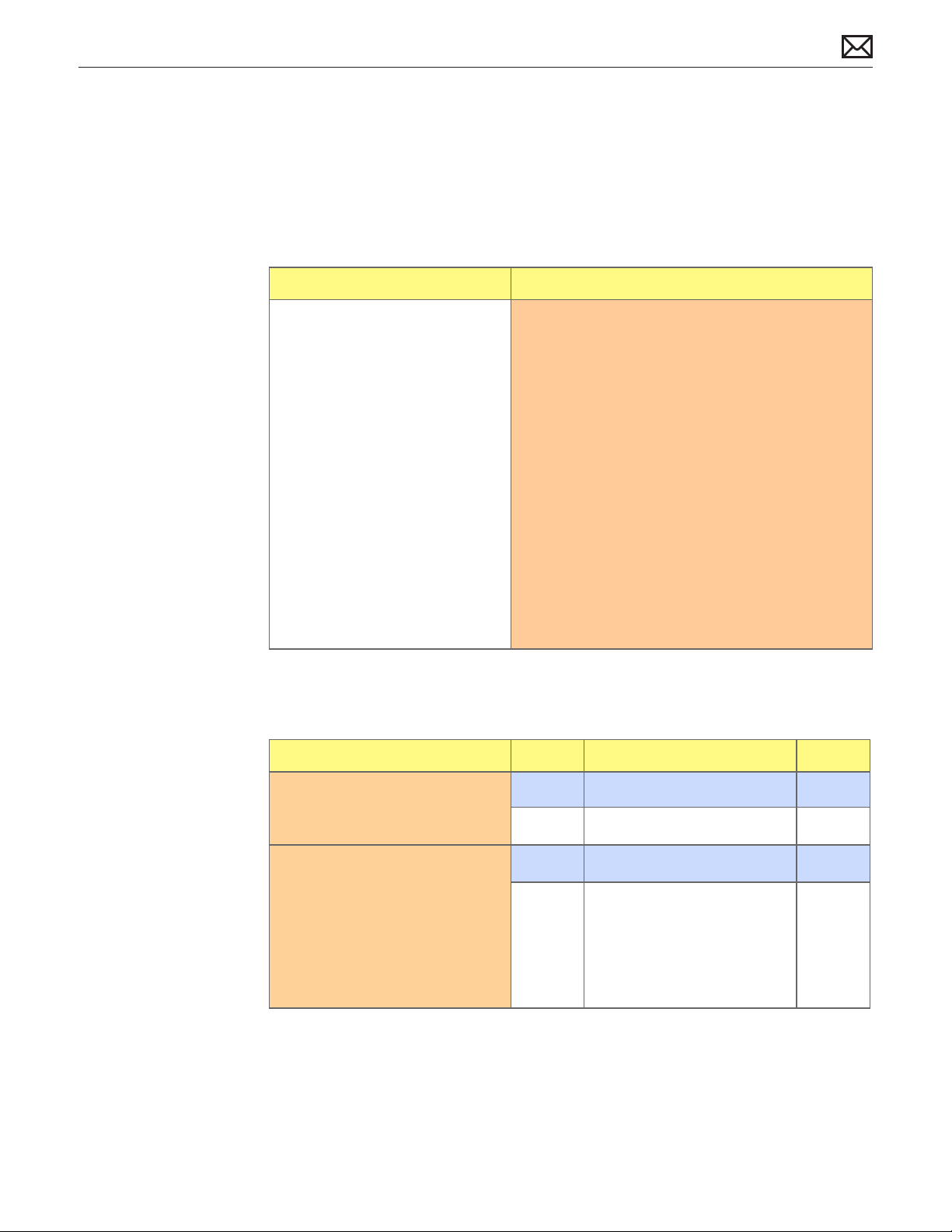
Input/Output Devices
Rear USB Port Does Not Recognize Known Devices
Quick Check
Symptom Quick Check
Rear USB Port Does Not
Recognize Known Devices
• USB devices not recognized on
the rear USB port.
1. If the Xserve is locked, unlock it.
2. Check the for latest software updates for Apple
and especially third party devices.
3. Use System Proler to verify the System
recognizes each of the USB buses in the USB
device tree.
4. Test both rear ports with known good Apple
keyboard or mouse.
5. Test front USB port with known good Apple
keyboard or mouse.
6. Verify any external USB device with large power
requirements have their own external power
supplies.
7. Verify external USB device cables by using known
good cables.
Deep Dive
Check Result Action Code
2010-06-28
1. Disconnect all peripherals
except for a known good
Apple USB device.
2. Verify the USB ports are free
from contaminants and debris.
Yes Go to step 2
No Repeat Step 1
Yes Go to step 3
No Remove contaminants and
debris. Replace aected
modules if necessary. Defects
caused by contaminants or
debris are not covered by
Apple warranty. Go to step 3.
Xserve (Early 2009) Symptom Charts — Input/Output Devices 61
Page 62

3. Reset SMC. Verify each of the
USB buses are recognized, and
a known good connected USB
device is recognized?
Yes Issue resolved. Issue maybe
caused by another peripheral
device.
No Replace Logic Board. M15
Front USB Port Does Not Recognize Known Devices
Quick Check
Symptom Quick Check
Front USB Port Does Not Recognizing
Known Devices
• USB devices not recognized on the
front USB port.
1. If the Xserve is locked, unlock it.
2. Check the for latest software updates for
Apple and especially third party devices.
3. Use System Proler to verify the System
recognizes each of the USB buses in the
USB device tree.
4. Test both rear ports with known good
Apple keyboard or mouse.
5. Verify any external USB device with large
power requirements have their own
external power supplies.
6. Verify external USB device cables by using
known good cables.
Deep Dive
Check Result Action Code
1. Disconnect all peripherals
except for a known good
Apple USB device.
Yes Go to step 2
No Repeat Step 1
2010-06-28
2. Verify the USB ports are free
from contaminants and debris.
Yes Go to step 3
No Remove contaminants and
debris. Replace aected
modules if necessary. Defects
caused by contaminants or
debris are not covered by
Apple warranty. Go to step 3.
Xserve (Early 2009) Symptom Charts — Input/Output Devices 62
Page 63

3. Reset SMC. Verify each of the
USB buses are recognized, and
a known good connected USB
device is recognized?
Yes Issue resolved. Issue maybe
caused by another peripheral
device.
No Go to step 4.
4. Reseat the Front Panel Board
cable.
Yes Issue resolved.
No Replace Front Panel Board. M15
FireWire Port Does Not Recognize Known Devices
Quick Check
Symptom Quick Check
FireWire Port Does Not
Recognize Known Devices
• FireWire devices not
recognized.
1. If the Xserve is locked, unlock it.
2. Check the for latest software updates for Apple
and especially third party devices.
3. Use System Proler to verify the System
recognizes each of the FireWire busses in the
FireWire device tree.
4. Test both rear ports with known good FireWire
device and cable.
N08
5. Verify any external FireWire device with large
power requirements have their own external
power supplies.
6. Verify external FireWire device cables by using
known good cables.
7. Reset PRAM/NVRAM.
Deep Dive
Check Result Action Code
1. Disconnect all peripherals
except for a known good
FireWire device and cable.
Yes Go to step 2
No Repeat Step 1
2010-06-28
Xserve (Early 2009) Symptom Charts — Input/Output Devices 63
Page 64

2. Verify the FireWire ports are
free from contaminants and
debris.
Yes Go to step 3
No Remove contaminants and
debris. Replace aected
modules if necessary. Defects
caused by contaminants or
debris are not covered by
Apple warranty. Go to step 3.
3. Reset SMC. Verify each of the
FireWire busses are recognized,
and a known good connected
Firewire device is recognized?
Yes Issue resolved. Issue maybe
caused by another peripheral
device.
No Replace Logic Board. M12
PCI-E Expansion Card/Slot Not Recognized
Quick Check
Symptom Quick Check
I/O Expansion Issues
• Expansion riser/slot issues
• Can’t detect expansion card
1. For Ethernet card issues, make sure to congure
using Network System Preference
2. For Fibre channel card issues, make sure to
congure using Fibre Channel Utility.
3. For SCSI card issues, make sure to congure
using Disk Utility.
4. Check System Proler to see if the card is
recognized.
2010-06-28
5. Reset PRAM/NVRAM
6. Run AXD diagnostics and check log les.
Xserve (Early 2009) Symptom Charts — Input/Output Devices 64
Page 65

Deep Dive
Check Result Action Code
1. Does the expansion card meet
the requirements for the slot
in which it is being used?
2. Reset SMC. Yes Issue resolved.
3. Reseat the expansion card. Yes Issue resolved.
4. Reseat the PCI riser card into
the logic board, and retest the
card in the same slot.
5. Test the expansion card in
the other expansion slot,
if available, ensuring the
card being tested meets the
requirements of the slot.
Yes Go to step 2.
No Refer to product specications
of Xserve then recommend
the card be replaced with the
proper specication type of
model.
No Go to step 3.
No Go to step 4.
Yes Issue resolved.
No Go to step 5.
Yes Issue resolved.
No Go to step 6.
6. Test with a dierent known
good compatible card in the
same type of slot.
7. Test with a known good PCI
riser card.
8. Does the expansion card work
with the replacement logic
board?
Yes Issue resolved.
No Go to step 7.
Yes Issue resolved.
No Replace Logic Board. M17
Yes Issue resolved.
No Repeat steps 3-7.
2010-06-28
Xserve (Early 2009) Symptom Charts — Input/Output Devices 65
Page 66

Uncategorized Symptom
Quick Check
Symptom Quick Check
Uncategorized Symptom
Unable to locate appropriate
symptom code
Verify whether existing symptom code applies to the
issue reported by the user. If not, document reported
symptoms and send feedback to smfeedback@apple.
com stating that suitable symptom code could not
be found.
2010-06-28
Xserve (Early 2009) Symptom Charts — Input/Output Devices 66
Page 67

Communications
Ethernet Port/Device Issues
Quick Check
Symptom Quick Check
Network Issues
• Server cannot be seen on
network
• Slow network performance
1. Open the Network system preference pane and
select the built-in Ethernet option.
2. If only one Ethernet port is in use, verify that it
is the right hand (1) port. If it is not, move the
Ethernet cable to the right hand (1) port. This is
the primary (en0) port.
3. Boot the Xserve from the Installation disc. Go to
another computer on the same subnet and start
Server Assistant. If the Xserve can be seen, the
Xserve hardware should be functioning correctly.
Check the software conguration on the Xserve,
or reinstall and recongure the Xserve.
4. Try a known-good Ethernet cable.
5. Clear parameter RAM (PRAM). Hold down
Command-Option-P-R during startup. (You must
unlock the Xserve to perform PRAM reset)
6. Try connecting to a known-good Ethernet port at
the wall or external hub.
7. Verify that other users are experiencing the same
problem. If so, contact the network administrator.
2010-06-28
Deep Dive
Check Result Action Code
1. Is the Ethernet network
connected to an Ethernet
expansion card in the Xserve?
Yes See expansion card
troubleshooting section.
No Using built-in Ethernet. Go to
step 2.
Xserve (Early 2009) Symptom Charts — Communications 67
Page 68

2. Visually inspect Ethernet
connector to ensure all pins
will make physical contact with
CAT5 or better network cable.
Yes Ethernet interface contacts
are good. Go to step 3.
3. Isolate OS by booting from
original install media. Verify
network link status active
by using Network Utility on
install DVD and looking for link
LED adjacent to connected
Ethernet port. If the Ethernet
interface (en0) link status
is inactive, recheck physical
connection and link activity
indicator on hub/ switch.
4. Disconnect Xserve and
connect known-good
computer to network using
the same Ethernet cable. Verify
if IP address is listed for the
Ethernet interface in System
Preferences: Network. Retest.
No Pins are damaged or bent at,
replace logic board.
Yes Right-hand (1) Ethernet
interface (en0) Link Status is
active, go to step 4.
No Right-hand (1) Ethernet
interface (en0) Link Status is
inactive. Replace logic board.
Yes Go to step 5.
No If connection is OK on known-
good system, replace logic
board.
M10
M10
M10
2010-06-28
5. Verify connection by using
Network Utility to ping another
connected computer on the
same subnet. Ensure the
target computer‚ IP address is
valid, on the same subnet and
powered on. Ensure no MAC
address ltering or hardware
access control devices are
present. Use a simple hub/
switch environment. Is ping
successful?
Yes Go to step 6.
No If the symptoms do not
M10
change, replace the logic
board.
Xserve (Early 2009) Symptom Charts — Communications 68
Page 69

6. Verify Ethernet performance
and reliability by starting up
from a known-good OS install,
and downloading a large le
from a web site or le server.
Yes If there is performance or
connectivity issue isolated
solely to the system under
test, the problem may be the
network environment. No
repair is necessary.
No If there are connection
Uncategorized Symptom
Quick Check
Symptom Quick Check
Uncategorized Symptom
Unable to locate appropriate
symptom code
Verify whether existing symptom code applies to the
issue reported by the user. If not, document reported
symptoms and send feedback to smfeedback@apple.
com stating that suitable symptom code could not
be found.
M10
dropouts or poor
performance not seen on
a known-good test system,
replace the logic board.
2010-06-28
Xserve (Early 2009) Symptom Charts — Communications 69
Page 70

Video
Video Distortion
Quick Check
Symptom Quick Check
Video is distorted
• Bad/Dim color
• Lines or artifacts
• Distortion/garbled video
1. Refer to the adjustments section of the owner’s
manual for the external display. Adjust display as
necessary.
2. Reseat the Mini DisplayPort adapter and cable
connections.
3. Inspect the Mini DisplayPort adapter pins and
replace the adapter if necessary.
4. Reset PRAM/NVRAM. (You must unlock the Xserve
to perform)
5. Test with a known good display.
6. Run complete AXD Diagnostics
Deep Dive
Check Result Action Code
1. Reseat the mezzanine video
card
Yes Issue resolved.
No Replace the mezzanine video
card.
M04
2010-06-28
Xserve (Early 2009) Symptom Charts — Video 70
Page 71

No Video
Quick Check
Symptom Quick Check
External display has no video,
but activity lights ash at
startup, drive operates, fan array
is spinning, and power LED is
illuminated.
• Device has power and boots,
but no video output
Deep Dive
1. Conrm the system conguration supports
an external display. Not all congurations do,
although the Mini DisplayPort connector on
the rear of the unit is present regardless. Using
System Proler you can check the Graphics/
Displays section for the presence of a video card.
2. Reseat the external Mini DisplayPort adapter and
cable connections.
3. If you are using a Mini DisplayPort adapter,
inspect the adapter pins and replace the adapter
if necessary.
4. Reset PRAM/NVRAM.
5. Test with a known good display.
6. Remove all third party devices.
7. Run complete AXD Diagnostics.
2010-06-28
Check Result Action Code
1. Press the SMC Reset button
on the logic board to reset
the SMC. Is the issue resolved?
2. Check internal diagnostic LEDs.
Go to diagnostic LED section
for more information. Is the
issue resolved?
3. Reseat the mezzanine video
card. Is the issue resolved?
4. With replacement mezzanine
video card is the issue
resolved?
Yes Issue resolved.
No Go to Step 2
Yes Issue resolved.
No Go to Step 3
Yes Issue resolved.
No Replace mezzanine video
card. Go to step 4.
Yes Issue resolved.
No Replace Logic Board. M03
Xserve (Early 2009) Symptom Charts — Video 71
M03
Page 72

Mechanical Issues: Thermal and Enclosure
Failed or Fast Fans
Quick Check
Symptom Quick Check
System Fast/Failed Fans
• System feels very warm
• Computer is sluggish
• Fan(s) running fast
• Fan(s) not running at all
1. Verify the System has adequate airow around
the enclosure, front and rear vents not blocked.
2. Verify the issue is not user perception - System
functions correctly, and not running any warmer
than expected. Compare to a similarly congured
System. Processes running in the background may
go unnoticed by the user.
3. Understand temperatures and fan speed will
uctuate within a normal range depending on
processes running, and attached peripherals.
Fan(s) speeds may take several minutes to return
to idle after heavy CPU or I/O activity has ceased.
4. Verify correct specication memory is used.
Ensure the installed memory is congured
correctly to optimize performance.
5. If there is abnormal temperature the overall
System speed will be noticeably reduced. If the
abnormal temperature cannot be reduced to
within the normal range a force shutdown will
occur. These events are recorded in System.log.
Check Xserve logs for any “runaway” applications
or processes consuming the CPU’s.
2010-06-28
Deep Dive
Check Result Action Code
1. Verify if the issue is user
perception of intermittent
noisy fans. Is the System
running as expected
(compared to a similar
system)?
Xserve (Early 2009) Symptom Charts — Mechanical Issues: Thermal and Enclosure 72
Yes No problem found. Inform
the customer the system is
operating normally.
No Go to step 2.
Page 73

2. Determine if there are runaway
applications or processes
consuming the CPU’s - Verify
using ‘Activity Monitor’. Are
any runaway applications or
processes present?
Yes The application or process
may have crashed.
Alternatively check with
the software vendor for
compatibility and software
update.
No There are no runaway
applications or processes. Go
to step 3.
3. Press the SMC Reset button
on the logic board to reset the
SMC. Verify all fans are rotating
at close to minimum speed
within a few minutes after the
system is idle
4. Check internal diagnostic LEDs.
Go to diagnostic LED section
for more information. Verify
all fans are rotating at close
to minimum speed within a
few minutes after the system
is idle.
5. Boot the System from a known
good external volume. Verify
all fans are rotating at close
to minimum speed within a
few minutes after the system
is idle.
Yes Issue resolved.
No Go to Step 4
Yes Issue resolved.
No Go to Step 5
Yes Suspect issue is caused by
customer software or Mac
OS X install. Backup all data,
restore unit from the Mac
OS X install discs and restore
from the backup.
No Go to step 6
2010-06-28
Xserve (Early 2009) Symptom Charts — Mechanical Issues: Thermal and Enclosure 73
Page 74

6. Clear out any obstructions
such as dust or internal
cables from the fan array
and heatsinks. Reseat fan
array connections to drive
interconnect backplane. Ensure
no damage to heatsinks ie
bent or crushed ns. Reseat
CPU(s) and heatsink(s). Run
Server Monitor and AXD to
verify the thermal sensor and
fan circuity is functioning
correctly. Verify all fans are
rotating at close to minimum
speed within a few minutes
after the system is idle.
Yes Issue resolved
No Replace aected component
based on AXD, internal
diagnostic LEDs, and Server
Monitor ndings:
- Fan Array failures
- Drive Interconnect
Backplane won’t drive the
known good fan failures
- Sensor related failures
- For Heatsink failures
X18
M18
M23
M99
2010-06-28
Xserve (Early 2009) Symptom Charts — Mechanical Issues: Thermal and Enclosure 74
Page 75

Apple Technician Guide
Take Apart
Xserve (Early 2009)
© 2008 Apple Inc. All rights reserved.
Page 76

General Information
Orientation
For most take-apart procedures, Apple recommends removing the computer from the rack
before removing or installing the part.
Tools
The following tools are required to service all congurations of the computer:
• Magnetized Phillips #1 screwdriver
• Magnetized Phillips #2 screwdriver
• Magnetized 3 mm Hex screwdriver
• Xserve Allen wrench key
• Thermal grease kit (Apple part number 076-1225)
• Nylon probe tool (Apple part number 922-5065)
• Alcohol wipes
• Soft cloth (for protecting the enclosure from scratches)
2010-06-28
How to Identify Single- and Dual-Processor Congurations
See “How to Identify Single- and Dual-Processor Congurations” in the Basics chapter.
Mounting in a Rack
For information on mounting Xserve (Early 2009) in a rack, see the Xserve (Early 2009) Setup
Guide.
Xserve (Early 2009) Take Apart — General Information 76
Page 77

Icon Legend
The following icons are used in this chapter:
Icon Meaning
Warning or caution
Check; make sure you do this
Challenging procedure; requires more
thought and/or time until you are
familiar with it
Note on Illustrations
Because a pre-production model was used for the illustrations in this manual, you may notice
small dierences between the image pictured and the computer you are servicing.
2010-06-28
Xserve (Early 2009) Take Apart — General Information 77
Page 78

First Steps
Caution: Make sure data
is backed up before
removing or replacing the
drive.
.
Apple Drive Module
Tools
• Xserve Allen wrench
key
2010-06-28
Xserve (Early 2009) Take Apart — Apple Drive Module 78
Page 79

Removal
1 Make sure the locking
mechanism is in the
unlocked position.
2 Make sure the drive being replaced is not in use by any application and is not being shared
by the Xserve. (See the Mac OS X Server documentation for information about shared
drives.)
3 Unmount the drive (by using the command-line tools or by dragging the volume icon to
the Trash.).
4 Press the handle on
the drive. Wait for the
upper LED to turn o
2010-06-28
Xserve (Early 2009) Take Apart — Apple Drive Module 79
Page 80
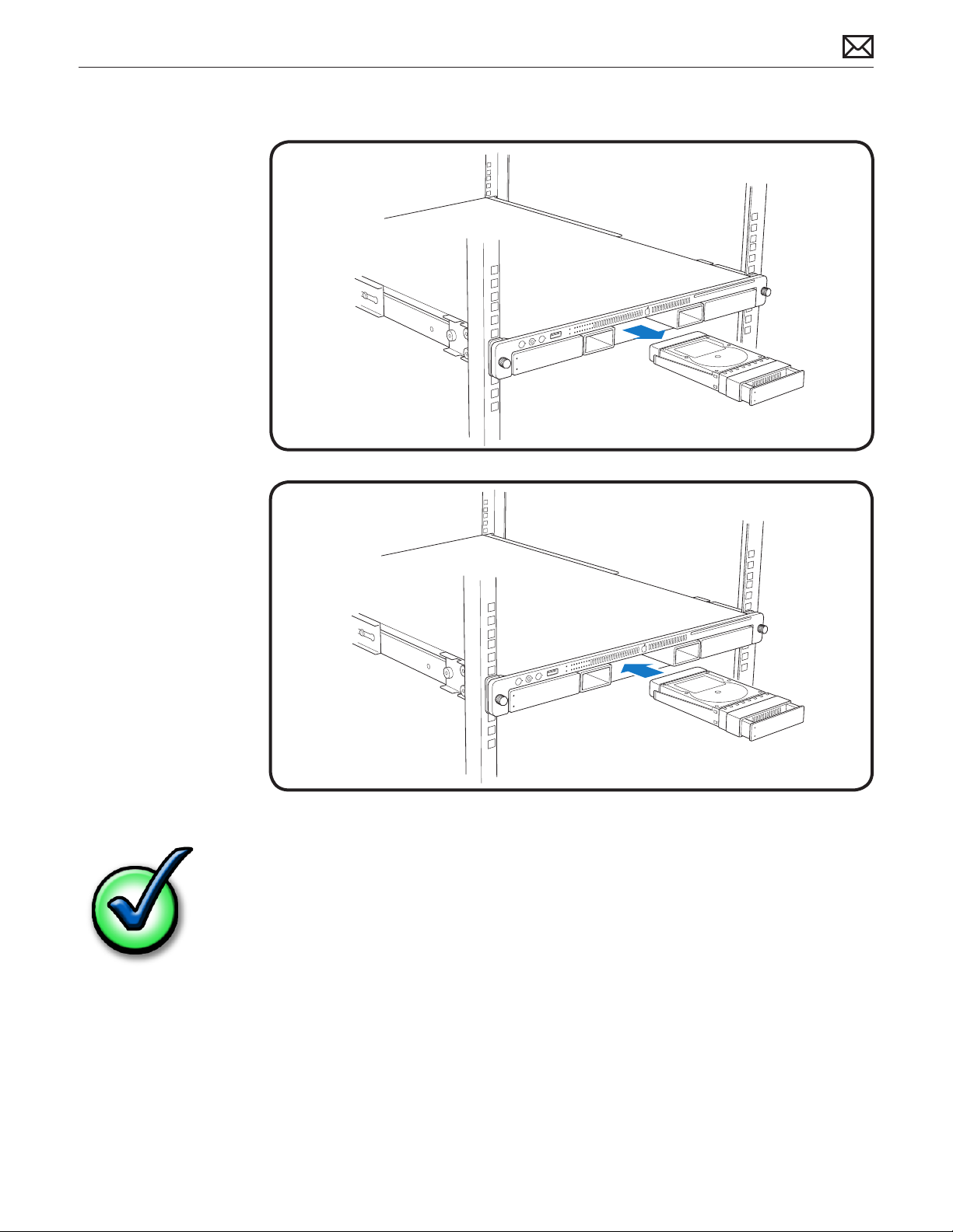
5 Grasp handle on the
replacement drive.
Pull module out of
the Xserve.
Replacement
1 Slide module into the
bay until it is rmly
seated.
2 Press the handle ush
with the front panel.
Replacement Note: If you
replace the hard drive
with a new one, format
the new drive.
2010-06-28
Xserve (Early 2009) Take Apart — Apple Drive Module 80
Page 81

First Steps
Warning: If the Xserve has
only one power supply,
shutdown computer.
Power Supply
Tools
• ESD wrist strap
2010-06-28
Xserve (Early 2009) Take Apart — Power Supply 81
Page 82

Removal
1 Unplug the power
cord from the power
supply.
2 Pull handle to release
the power supply.
3 Slide out of the bay.
Note: If the Xserve is already running on a second power supply, the status light on the new
power supply turns green to indicate normal operation as it stars sharing the load. If the Xserve
is not turned on, the status light blinks green when the power cord is plugged in to an outlet
with power.
Replacement
1 Pull handle on the
new power supply.
2 Slide the power
supply all the way
into bay.
3 Press handle to seat
properly and lock it in
place.
4 Connect power cord
to power supply.
2010-06-28
Xserve (Early 2009) Take Apart — Power Supply 82
Page 83
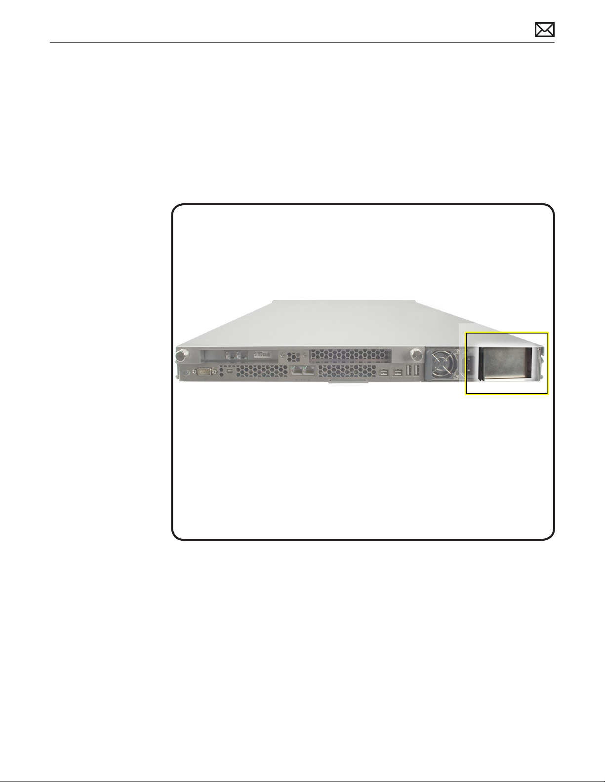
First Steps
• No rst steps for this
procedure.
Power Supply Blank
Tools
• No tools required
2010-06-28
Xserve (Early 2009) Take Apart — Power Supply Blank 83
Page 84

Removal
1 Pull the handle to
swing open the
power supply blank.
2 Notice the hook that
catches on the inside
bottom of the power
supply bay.
3 Open the power
supply blank as far
as it will go, and pull
out the power supply
blank.
Replacement
1 Align the hook on the
power supply blank
with the catch inside
the power supply bay.
2 Close the power
supply blank and
press handle over the
bay wall to lock it in
place
2010-06-28
Xserve (Early 2009) Take Apart — Power Supply Blank 84
Page 85

First Steps
Write down the Xserve
serial number. If the
Xserve’s software must
be setup after service
is complete, the serial
number will be required.
Top Cover
Tools
• ESD wrist strap
• Xserve Allen wrench
key
• Phillips #1 screwdriver
(optional)
2010-06-28
Xserve (Early 2009) Take Apart — Top Cover 85
Page 86

Removal
1 Shutdown the
Xserve and wait a
few moments for
components to cool.
2 If the Xserve case
is locked, use the
Xserve Allen wrench
to unlock the security
lock on the front
panel.
3 Unplug all cables
from the Xserve..
4 Loosen the
thumbscrews at the
back of the top cover
and slide cover back
and up to remove it.
Replace
1 Replace and secure
the cover.
2 Tighten the
thumbscrews at the
back of the top cover.
2010-06-28
Xserve (Early 2009) Take Apart — Top Cover 86
Page 87

First Steps
Remove:
• Top Cover
Solid State Drive
Tools
• ESD wrist strap and
mat
• Black stick
2010-06-28
Xserve (Early 2009) Take Apart — Solid State Drive 87
Page 88

Removal
1 Disconnect the SSD
cable from the Front
Panel Board.
2 Gently press the two
tabs out to release
the drive. It may be
helpful to use the
black stick under the
drive.
Replacement
1 Note the orientation
of the drive. The
connector on the
drive should be facing
up. The label should
face down.
2 The drive connector
should be facing the
front of the Xserve.
3 Place the SSD drive
into the SSD drive
carrier.
4 Connect the SSD
cable to the front
panel board.
2010-06-28
Xserve (Early 2009) Take Apart — Solid State Drive 88
Page 89

First Steps
Remove:
• Top Cover
• Solid State Drive
.
Solid State Drive Cable
Tools
• ESD wrist strap
• Black stick
2010-06-28
Xserve (Early 2009) Take Apart — Solid State Drive Cable 89
Page 90

Removal
1 Disconnect Solid-
State Drive cable from
the Front Panel Board.
2 Lift the Kapton tape
from the Solid-State
Drive.
3 Using the black stick,
gently ip up the
locking lever.
4 Gently slide the Solid-
State Drive cable out
of connector.
Replacement
1 Slide connector into
receptacle on the
Solid-State Drive.
2 Lock down lever after
inserting cable.
3 Replace Kapton tape
over the connector on
drive.
4 Connect the cable to
the Front Panel Board.
2010-06-28
Xserve (Early 2009) Take Apart — Solid State Drive Cable 90
Page 91

First Steps
Remove:
• Top Cover
• Solid State Drive
.
Solid State Drive Carrier
Note: Adhesive on the bottom side of the solid state drive carrier attaches it to the enclosure.
Whenever you detach the carrier from the enclosure, you must install a replacement carrier
(part number 922-8959). Otherwise, the used adhesive may not hold the carrier rmly in place.
Tools
• ESD wrist strap
• Black stick
2010-06-28
Xserve (Early 2009) Take Apart — Solid State Drive Carrier 91
Page 92
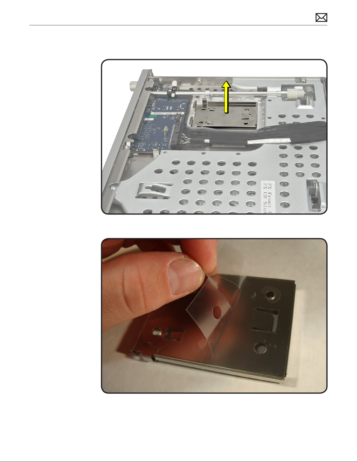
Removal
1 Gently lift the carrier
from the adhesive on
the enclosure.
Replacement
Note: The adhesive on
the replacement carrier is
located on the bottom of
the carrier and covered by
a protective lm.
1 Peel o the lm
covering the carrier’s
adhesive.
2010-06-28
Xserve (Early 2009) Take Apart — Solid State Drive Carrier 92
Page 93
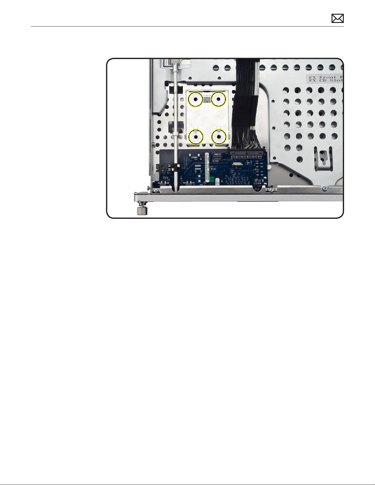
2 Position the carrier
adhesive side down.
Align the holes in the
carrier with the four
enclosure holes
indicated and press
down.
2010-06-28
Xserve (Early 2009) Take Apart — Solid State Drive Carrier 93
Page 94

First Steps
Remove:
• Top Cover
Apple recommends that
you use Apple-approved
DIMMs. DIMMs from
older Xserve systems are
not compatible with this
Xserve.
Memory
Tools
• ESD wrist strap and
mat
2010-06-28
Xserve (Early 2009) Take Apart — Memory 94
Page 95

Removal
1 Open ejectors on
DIMM slots.by
pushing them out to
the sides.
2 Holding the DIMM by
edges, remove it from
connector.
3 Do not touch the
gold connectors.
Warning: DIMMs may be
very hot. Always wait 5-10
minutes for computer
to cool down .before
removing or installing
memory
.
Memory Slot Utility
2010-06-28
If the DIMM conguration you install does not provide optimized performance, the Memory Slot
Utility will appear on screen and recommend an improved conguration. To use the Memory
Slot Utility, go to /System/Library/Core Services.
Xserve (Early 2009) Take Apart — Memory 95
Page 96

Replacement
Replacement Note: The
DIMM is designed to t
into the slot only one way.
Be sure to align the notch
on the DIMM with the slot.
1 Align.the notch on
the DIMM with the
slot.
2 Push both ends of
DIMM down until
ejectors snap back up
into place.
Memory
Conguration
2010-06-28
Xserve (Early 2009) comes with a minimum of 3 GB of memory installed as three 1 GB
unbuered dual inline memory module (UDIMMs).
DIMMs must t these specications:
• PC3-8500 1066MHz, DDR SDRAM UDIMMs
• Error-correcting code (ECC)
For proper operation of Xserve computers, Apple recommends using only Apple-approved
DIMMs. Refer to GSX for Apple DIMM service part nubmers. Memory from older Xserve
computers is not compatible with Xserve (Early 2009).
Xserve (Early 2009) Take Apart — Memory 96
Page 97

First Steps
Remove:
• Top Cover
Important: Before you
begin this procedure,
verify the Xserve is turned
o and unplugged.
PCI-E Riser Cards
Tools
• ESD wrist strap and
mat
• Phillips #1 screwdriver
2010-06-28
Xserve (Early 2009) Take Apart — PCI-E Riser Cards 97
Page 98

Removal
1 Loosen the two
captive screws that
secure the riser
bracket to the back
panel.
2 Carefully pull up on
the bracket and riser
to disconnect from
the logic board.
3 If you are removing
a blank riser card to
install a card do the
following:
• Remove the screw on
the riser bracket
• Seat the PCI card
in the riser slot and
replace the screw to
secure in the riser.
Replacement
If you are replacing an
existing riser card do the
following:
• Remove any existing
expansion card from
the riser
• Transfer the card to
the replacement riser.
2010-06-28
Xserve (Early 2009) Take Apart — PCI-E Riser Cards 98
Page 99

First Steps
Remove:
• Top Cover
• PCI-E Riser Cards
Important: Before you
begin this procedure,
verify the Xserve is turned
o and unplugged.
PCI-E Expansion Cards
Tools
• ESD wrist strap and
mat
• Phillips #1 screwdriver
2010-06-28
Xserve (Early 2009) Take Apart — PCI-E Expansion Cards 99
Page 100
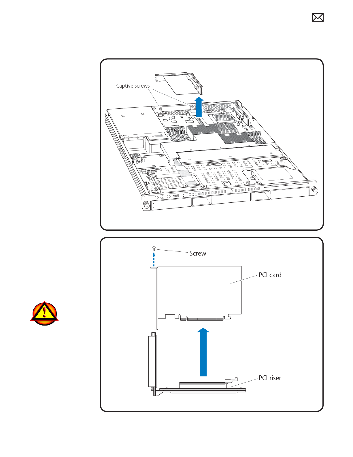
Removal
1 Loosen the two
captive screws that
secure the riser
bracket to the back
panel.
2 Carefully pull up on
the bracket and riser.,
with the expansion
card still attached to
disconnect from the
logic board.
3 Tilt the expansion
card up so the port
clears the enclosure,
and remove the card
from the Xserve.
4 Remove the screw
that secures the
expansion card to the
riser.
5 Gently separate the
card and riser.
Warning: When removing
or installing an expansion
card, handle it by the
edges. Do not touch
its connectors or any
components on the card.
Do not rock the card from
side to side or force the
card into the slot.
2010-06-28
Xserve (Early 2009) Take Apart — PCI-E Expansion Cards 100
 Loading...