

Page 1

Service Source
PowerBook G4 (Gigabit Ethernet)
Updated 22 May 2002
© 2002 Apple Computer, Inc. All rights reserved.
Page 2

Service Source
Take Apart
PowerBook G4 (Gigabit Ethernet)
© 2002 Apple Computer, Inc. All rights reserved.
Page 3

PowerBook G4 (Gigabit Ethernet)
Keyboard
Replacement Instructions
Follow the instructions in this sheet carefully. Failure to follow these instructions could
damage your equipment and void its warranty.
Note:
Written and video instructions covering customer-installable parts are available at
http://www.info.apple.com/installparts/.
Warning: During this procedure, keep small parts away from children.
Tools Required
The only tool required for this procedure is a jeweler’s flat-blade screwdriver
(if keyboard is locked).
Removing the Installed Keyboard
Warning: Always shut down your computer before opening it to avoid damaging its
internal components or causing injury. After you shut down the computer, the
internal components can be very hot. Let the computer cool down before
continuing.
1. Place your computer on a clean, flat surface.
2. Shut down your computer and wait thirty minutes before continuing.
3. Disconnect the power cord and any other cables connected to the computer.
073-0635 Rev. A
Page 4

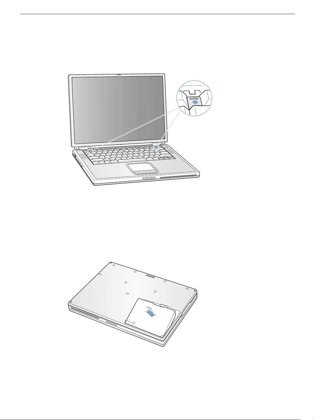
4. Close the computer and turn it over.
5. Slide the battery latch
(Figure 1A)
to the right to remove the battery
(Figure 1B)
Removing the battery will prevent you from accidentally turning on the computer.
Warning: Removing the battery before shutting down your computer may
result in data loss.
Figure 1
A
B
6. Turn over the computer.
7. Raise the display so you can access the keyboard.
.
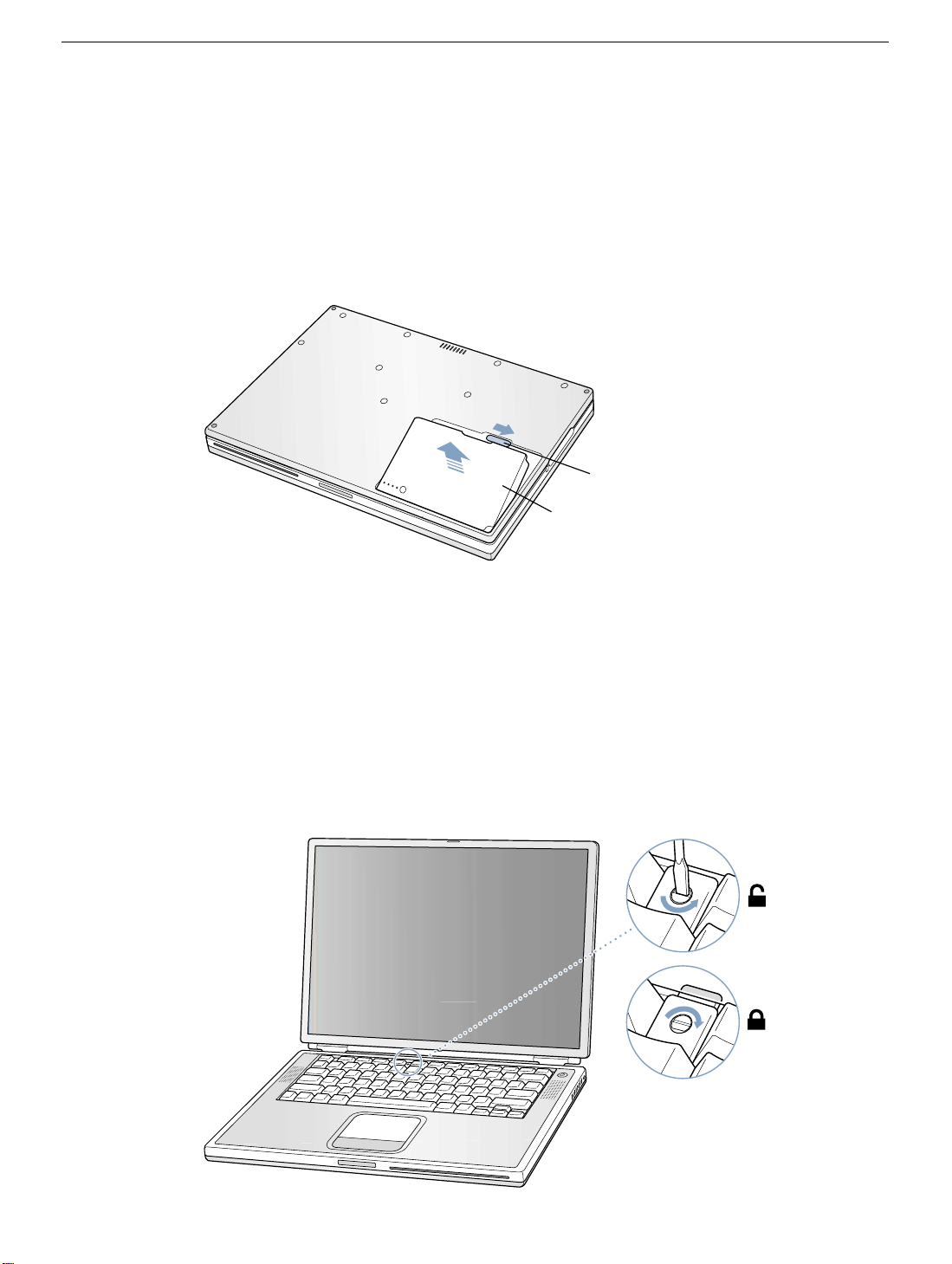
8. Make sure the keyboard loc king scre w, located in the small plastic tab to the left of the
Num Lock key
(Figure 2)
, is not in the locked position. Your PowerBook comes with
the keyboard unlocked, so unless you or someone else locked the keyboard, you can
skip this step.
To unlock the keyboard, turn the screw 1/2 turn.
Figure 2
PowerBook G4 (Gigabit Ethernet) Keyboard -
2
Page 5
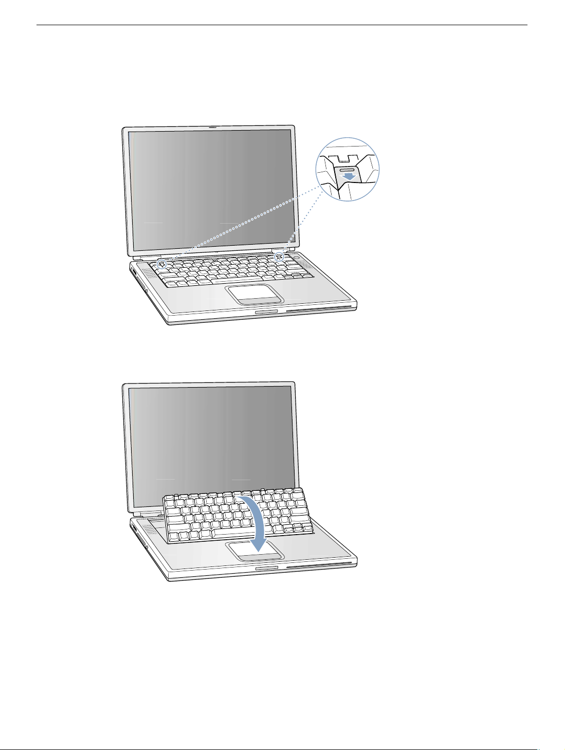
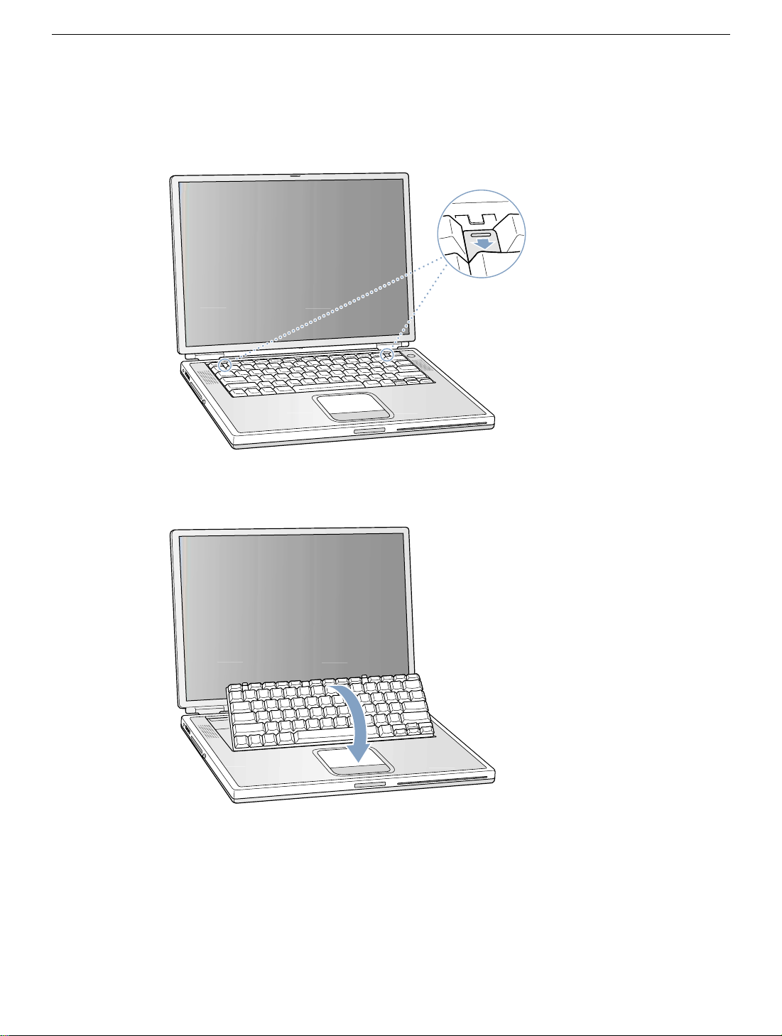
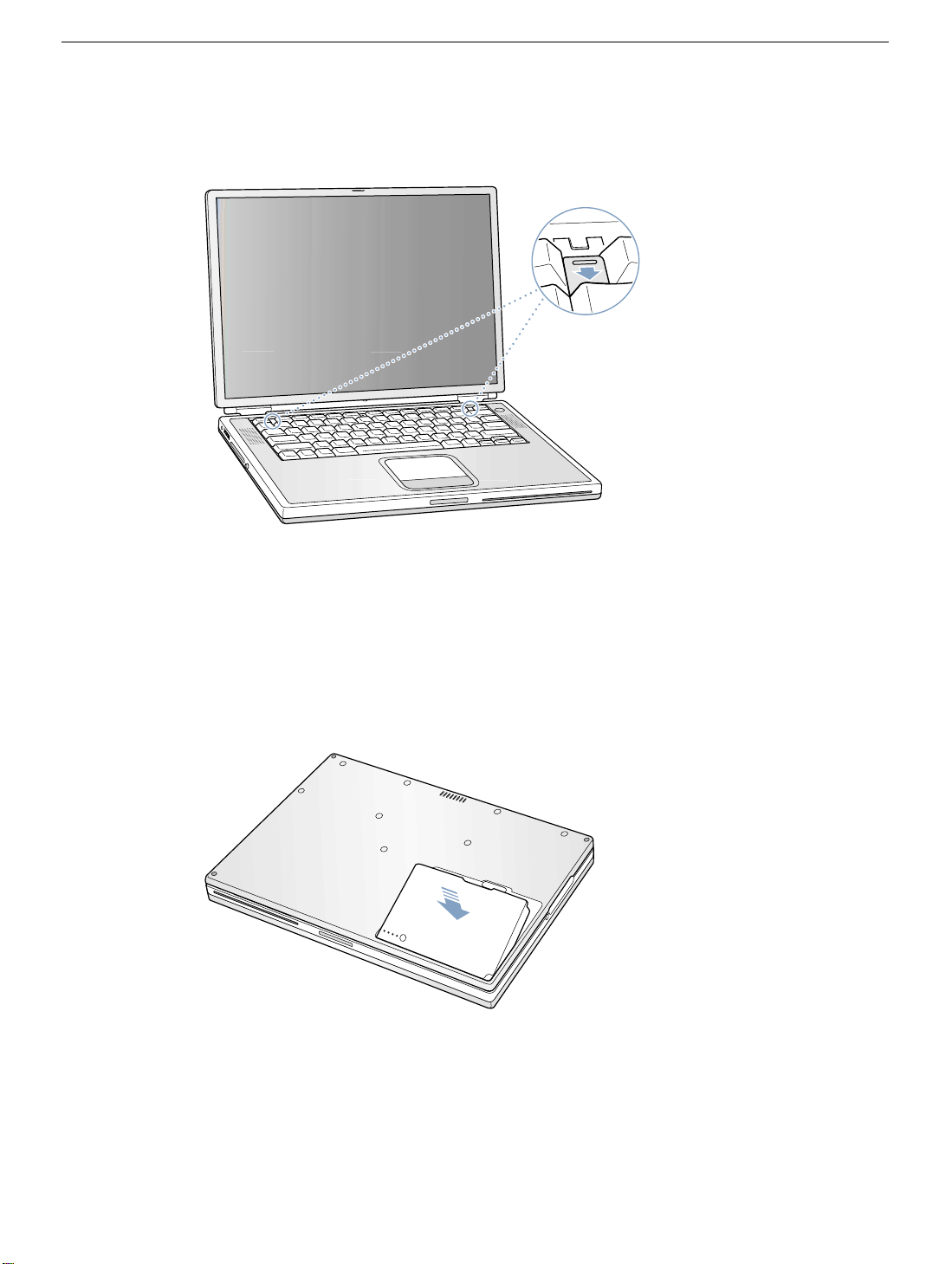
9. Release the keyboard by pulling do wn on the ke yboard release tabs (located to the left
of the F1 and F12 keys)
(Figure 3)
, then lift the top portion of the keyboard up slightly,
and toward the display.
Figure 3
®
10. Flip the keyboard over and lay it on the palm rests and trackpad.
Figure 4
(Figure 4)
PowerBook G4 (Gigabit Ethernet) Keyboard -
3
Page 6
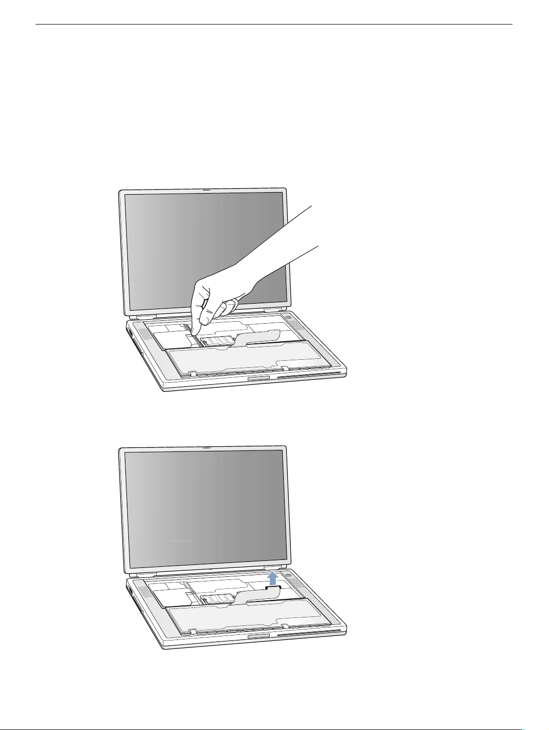
11. Touch the computer’s inside framework (a dull gray conductive composite material) to
discharge any static electricity, as shown
(Figure 5)
.
Important:
touching the computer’s framework before you touch any parts or install any
components inside the computer. To avoid static electricity building back up in your
body, do not walk around the room until you have completed your installation and
closed the computer.
Figure 5
To avoid electrostatic discharge damage, always ground yourself by
12. Locate the keyboard cable connector.
Figure 6
13. Pull up on the connector, from side to side if needed, to disconnect it from the computer .
14. Set the keyboard aside.
(Figure 6)
PowerBook G4 (Gigabit Ethernet) Keyboard -
4
Page 7
Installing the Replacement Keyboard
1. Lay the replacement keyboard in the correct orientation over the keyboard opening,
then flip it tow ard you and la y it f ace down on the palm rests and trac kpad to e xpose its
connector cable.
Figure 7
(Figure 7)
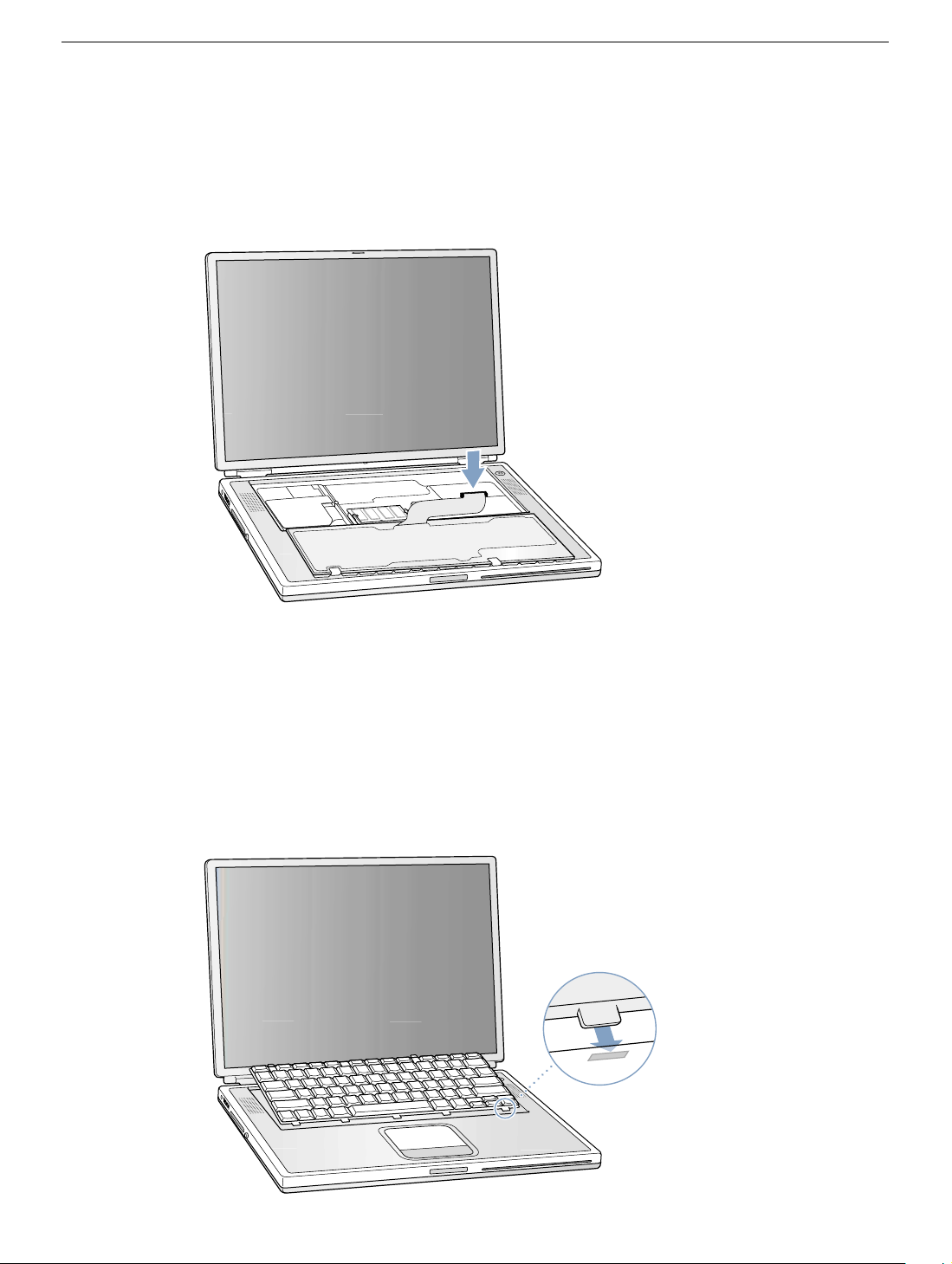
2. Firmly insert the keyboard cable connector into its connector on the computer.
3. Flip the keyboard back toward the keyboard opening in the case.
4. Hold the keyboard at an angle abov e the k eyboard opening, and insert the tabs on the
bottom edge of the keyboard into the slots below the edge of the opening.
Important:
against the edge of the opening.
Figure 8
Make sure that all the tabs are seated and that the keyboard rests flush
(Figure 8)
PowerBook G4 (Gigabit Ethernet) Keyboard -
5
Page 8
5. Lay the keyboard flat into the keyboard opening.
6. Pull down on the keyboard release tabs and then press do wn on the top portion of the
keyboard.
(Figure 9)
Figure 9
®
7. Release the tabs to secure the keyboard in place.
8. Close the display and turn the PowerBook over.
9. Replace the battery into the battery compartment.
(Figure 10)
Important: Make sure that the battery locks securely into place and that the battery
latch is slid all the way into the locked position.
Figure 10
10. Reconnect the power cord and any other cables that w ere connected, and restart your
computer.
Warning: Never turn on your computer unless all of its internal and external
parts are in place and it is closed. Operating the computer when it is open or
missing parts can damage your computer or cause injury.
PowerBook G4 (Gigabit Ethernet) Keyboard -
6
Page 9

Apple Computer, Inc.
© 2001 Apple Computer, Inc. All rights reserved.
Under the copyright laws, this document ma y not be copied, in whole or in part, without the
written consent of Apple.
The Apple logo is a trademark of Apple Computer, Inc., registered in the U.S. and other
countries. Use of the “keyboard” Apple logo (Option-Shift-K) for commercial purposes
without the prior written consent of Apple may constitute trademark infringement and
unfair competition in violation of federal and state laws.
Every effort has been made to ensure that the information in this document is accurate.
Apple is not responsible for printing or clerical errors.
Apple Computer, Inc.
1 Infinite Loop
Cupertino, CA 95014-2084
USA
+ 1 408 996 1010
http://www.apple.com
Apple, the Apple logo, and PowerBook are trademarks of Apple Computer , Inc., registered
in the U.S. and other countries.
PowerBook G4 (Gigabit Ethernet) Keyboard -
7
Page 10

PowerBook G4 (Gigabit Ethernet)
Memory Card
Replacement Instructions
Follow the instructions in this sheet carefully. Failure to follow these instructions could
damage your equipment and void its warranty.
Note:
Written and video instructions covering customer-installable parts are available at
http://www.info.apple.com/installparts/.
Warning: During this procedure, keep small parts away from children.
Tools Required
The only tool required for this procedure is a jeweler’s flat-blade screwdriver
(if keyboard is locked).
Opening the Computer
Warning: Always shut down your computer before opening it to avoid damaging its
internal components or causing injury. After you shut down the computer, the
internal components can be very hot. Let the computer cool down before
continuing.
1. Place your computer on a clean, flat surface.
2. Shut down your computer and wait thirty minutes before continuing.
3. Disconnect the power cord and any other cables connected to the computer.
Page 11

4. Close the computer and turn it over.
5. Slide the battery latch
(Figure 1A)
to the right to remove the battery
(Figure 1B)
Removing the battery will prevent you from accidentally turning on the computer.
Warning: Removing the battery before shutting down your computer may
result in data loss.
Figure 1
A
B
6. Turn over the computer.
7. Raise the display so you can access the keyboard.
.
8. Make sure the keyboard loc king scre w, located in the small plastic tab to the left of the
Num Lock key
(Figure 2)
, is not in the locked position. Your PowerBook comes with
the keyboard unlocked, so unless you or someone else locked the keyboard, you can
skip this step.
To unlock the keyboard, turn the screw 1/2 turn.
Figure 2
PowerBook G4 (Gigabit Ethernet) Memory Card -
2
Page 12
9. Release the keyboard by pulling do wn on the ke yboard release tabs (located to the left
of the F1 and F12 keys)
(Figure 3)
, then lift the top portion of the keyboard up slightly,
and toward the display.
Figure 3
®
10. Flip the keyboard over and lay it on the palm rests and trackpad.
Figure 4
(Figure 4)
PowerBook G4 (Gigabit Ethernet) Memory Card -
3
Page 13
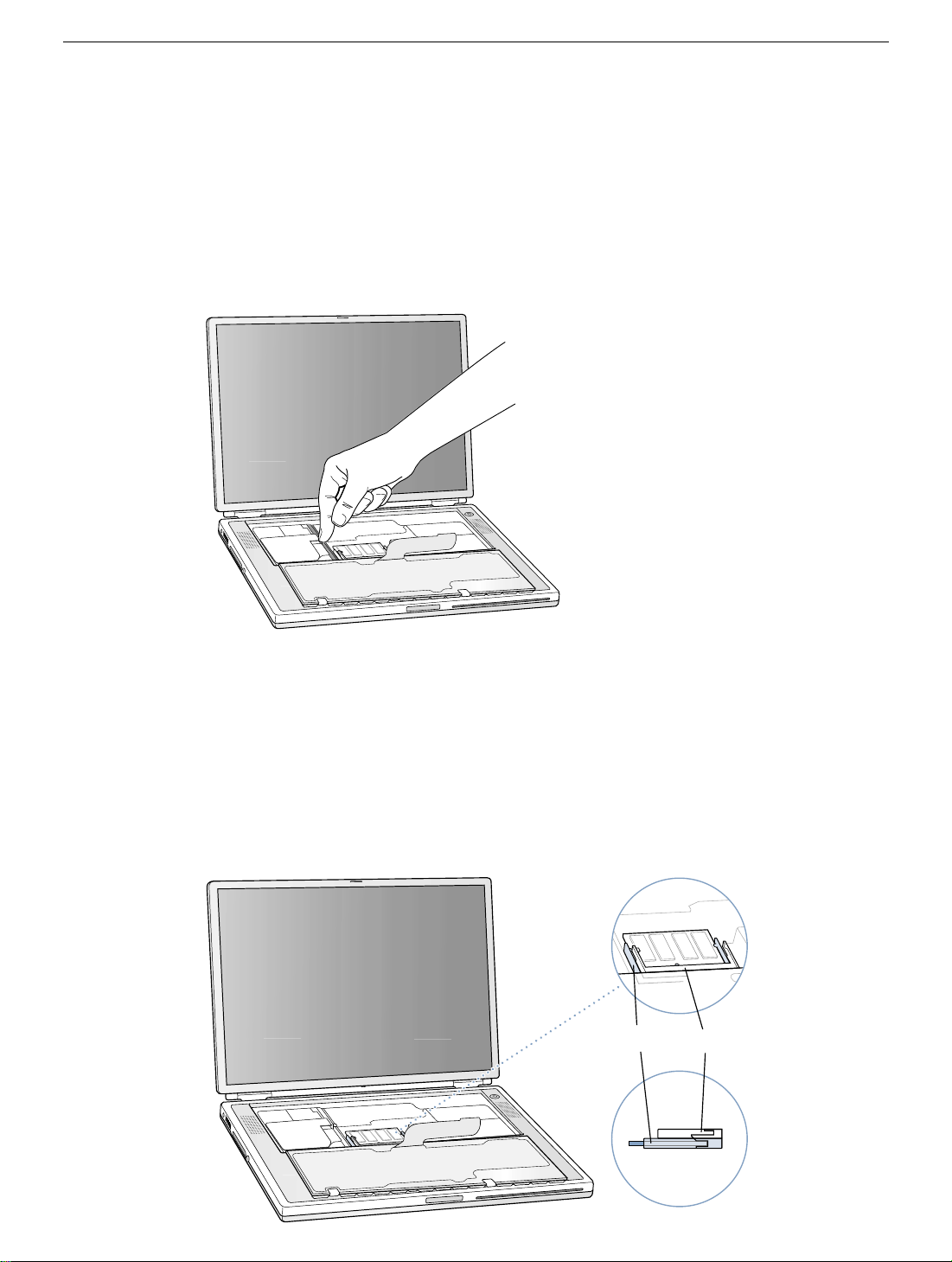
11. Touch the computer’s inside framework (a dull gray conductive composite material) to
discharge any static electricity, as shown
(Figure 5)
.
Important:
touching the computer’s framework before you touch any parts or install any
components inside the computer. To avoid static electricity building back up in your
body, do not walk around the room until you have completed your installation and
closed the computer.
Figure 5
To avoid electrostatic discharge damage, always ground yourself by
Removing the Installed Memory Card
1. To remove a memory card, locate the brackets that secure the card on both sides
(Figure 6)
Pull the card up and out.
Note:
removed before removing a card in the lower slot
Figure 6
. Carefully spread the brackets apart until the card releases on each side.
If there is a memory card in the upper memory slot
(Figure 6B)
B
(Figure 6A)
.
A
, it must be
PowerBook G4 (Gigabit Ethernet) Memory Card -
4
Page 14
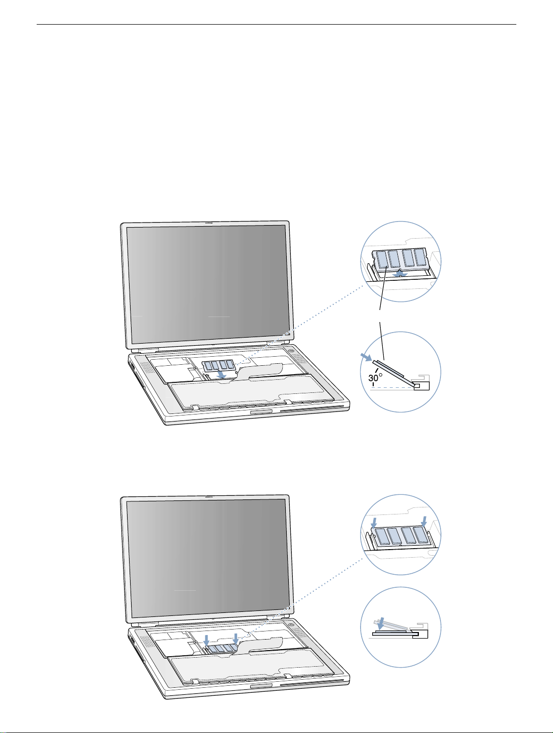
Installing the Replacement Memory Card
Warning: When handling a memory card, do not touch its gold connectors. Handle
the card only by the edges.
1. To install the memory card, line up the notch in the card with the small tab in the
memory slot. Hold the card
into the slot until it is firmly seated.
Note:
You may feel some resistance. If you are having trouble inserting the card, try
pushing one side at a time.
Figure 7
at a 30-degree angle
(Figure 7A)
A
, and then push the card
2. Gently push the card down until the two brackets on either side of the card lock into
place
(Figure 8)
Figure 8
.
PowerBook G4 (Gigabit Ethernet) Memory Card -
5
Page 15
Closing the Computer
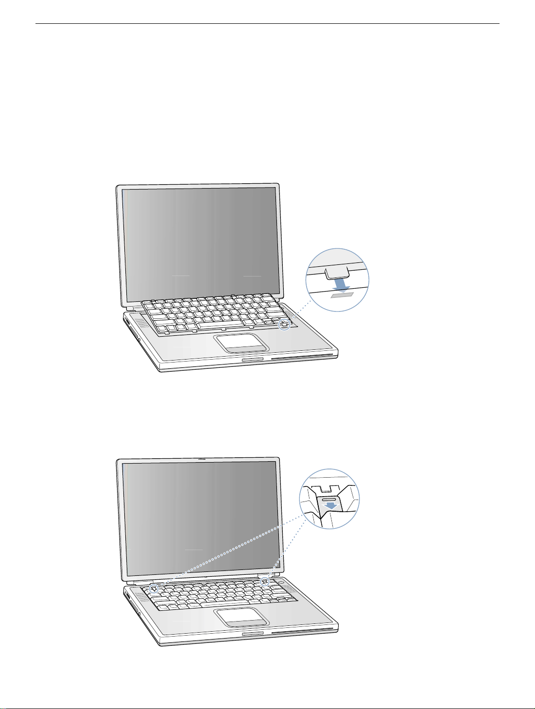
1. Flip the keyboard back toward the keyboard opening in the case.
2. Hold the keyboard at an angle abov e the k eyboard opening, and insert the tabs on the
bottom edge of the keyboard into the slots below the edge of the opening.
(Figure 9)
Important:
Make sure that all the tabs are seated and that the keyboard rests flush
against the edge of the opening.
Figure 9
3. Lay the keyboard flat into the keyboard opening.
4. Pull down on the keyboard release tabs and then press do wn on the top portion of the
keyboard.
(Figure 10)
Figure 10
®
5. Release the tabs to secure the keyboard in place.
PowerBook G4 (Gigabit Ethernet) Memory Card -
6
Page 16
6. Close the display and turn the PowerBook over.
7. Replace the battery into the battery compartment.
Important: Make sure that the battery locks securely into place and that the battery
latch is slid all the way into the locked position.
Figure 11
8. Reconnect the power cord and any other cables that w ere connected, and restart your
computer.
Warning: Never turn on your computer unless all of its internal and external
parts are in place and it is closed. Operating the computer when it is open or
missing parts can damage your computer or cause injury.
(Figure 11)
Apple Computer, Inc.
© 2001 Apple Computer, Inc. All rights reserved.
Under the copyright laws, this document ma y not be copied, in whole or in part, without the
written consent of Apple.
The Apple logo is a trademark of Apple Computer, Inc., registered in the U.S. and other
countries. Use of the “keyboard” Apple logo (Option-Shift-K) for commercial purposes
without the prior written consent of Apple may constitute trademark infringement and
unfair competition in violation of federal and state laws.
Every effort has been made to ensure that the information in this document is accurate.
Apple is not responsible for printing or clerical errors.
Apple Computer, Inc.
1 Infinite Loop
Cupertino, CA 95014-2084
USA
+ 1 408 996 1010
http://www.apple.com
Apple, the Apple logo, and PowerBook are trademarks of Apple Computer , Inc., registered
in the U.S. and other countries.
PowerBook G4 (Gigabit Ethernet) Memory Card -
7
Page 17

PowerBook G4 (Gigabit Ethernet)
Modem
Replacement Instructions
Follow the instructions in this sheet carefully. Failure to follow these instructions could
damage your equipment and void its warranty.
Note:
Written and video instructions covering customer-installable parts are available at
http://www.info.apple.com/installparts/.
Warning: During this procedure, keep small parts away from children.
Tools Required
• Jeweler’s flat-b lade screwdriver (if keyboard is locked)
• 5 mm wrench, 5 mm socket wrench, or needle nose pliers
Opening the Computer
Warning: Always shut down your computer before opening it to avoid damaging its
internal components or causing injury. After you shut down the computer, the
internal components can be very hot. Let the computer cool down before
continuing.
1. Place your computer on a clean, flat surface.
2. Shut down your computer and wait thirty minutes before continuing.
3. Disconnect the power cord and any other cables connected to the computer.
073-0634 Rev. A
Page 18
4. Close the computer and turn it over.
5. Slide the battery latch
(Figure 1A)
to the right to remove the battery
(Figure 1B)
Removing the battery will prevent you from accidentally turning on the computer.
Warning: Removing the battery before shutting down your computer may
result in data loss.
Figure 1
A
B
6. Turn over the computer.
7. Raise the display so you can access the keyboard.
.
8. Make sure the keyboard loc king scre w, located in the small plastic tab to the left of the
Num Lock key
(Figure 2)
, is not in the locked position. Your PowerBook comes with
the keyboard unlocked, so unless you or someone else locked the keyboard, you can
skip this step.
To unlock the keyboard, turn the screw 1/2 turn.
Figure 2
PowerBook G4 (Gigabit Ethernet) Modem -
2
Page 19

9. Release the keyboard by pulling do wn on the ke yboard release tabs (located to the left
of the F1 and F12 keys)
(Figure 3)
, then lift the top portion of the keyboard up slightly,
and toward the display.
Figure 3
®
10. Flip the keyboard over and lay it on the palm rests and trackpad.
Figure 4
(Figure 4)
PowerBook G4 (Gigabit Ethernet) Modem -
3
Page 20
11. Touch the computer’s inside framework (a dull gray conductive composite material) to
discharge any static electricity, as shown
(Figure 5)
.
Important:
touching the computer’s framework before you touch any parts or install any
components inside the computer. To avoid static electricity building back up in your
body, do not walk around the room until you have completed your installation and
closed the computer.
Figure 5
To avoid electrostatic discharge damage, always ground yourself by
Removing the Installed Modem
Warning: You must remove and install the modem carefully to avoid damaging
delicate parts, including the modem connector and connector cable.
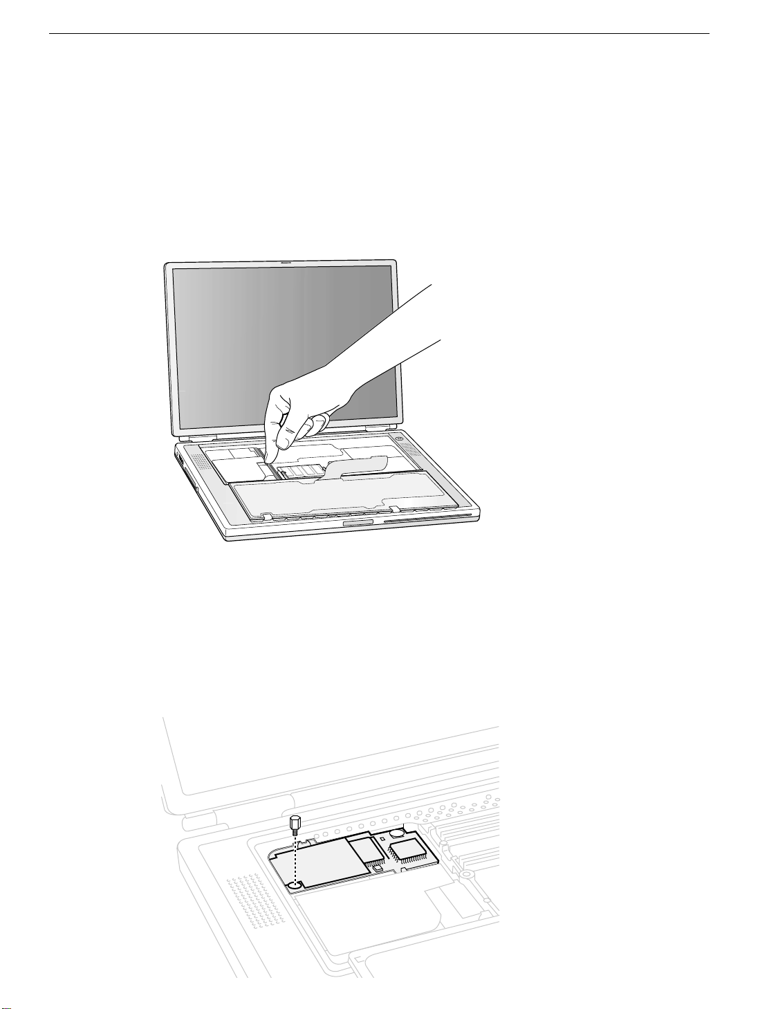
1. Locate the modem and remove the 5 mm hexnut screw
Figure 6
PowerBook G4 (Gigabit Ethernet) Modem -
(Figure 6A)
.
4
Page 21
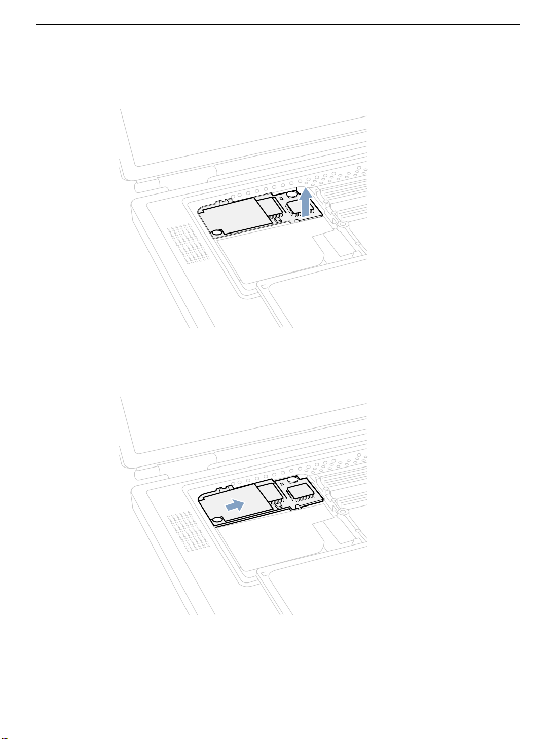
2. Pull up on the right, front corner of the modem to disconnect it from the logic board.
(Figure 7)
Figure 7
3. Pull the modem up and to the right slightly to reveal the modem connector cable
attached to the left end of the modem.
(Figure 8)
Figure 8
PowerBook G4 (Gigabit Ethernet) Modem -
5
Page 22
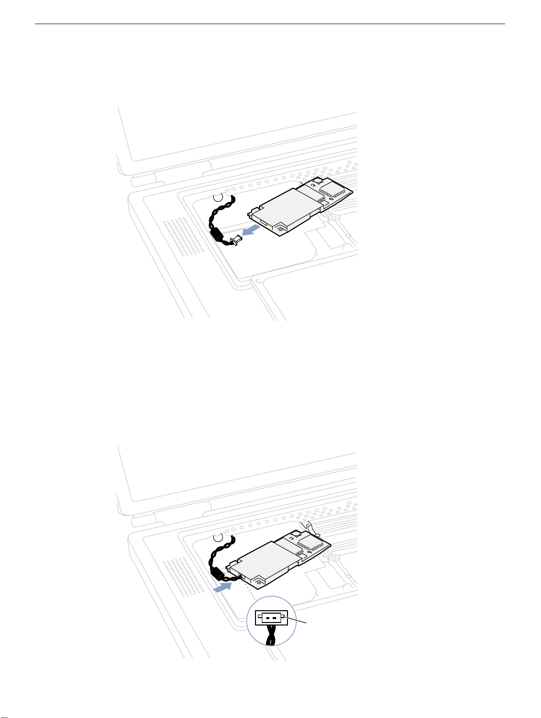
4. Carefully disconnect the modem cable connector
from the computer
Figure 9
.
(Figure 9)
and remove the modem
Installing the Replacement Modem
1. Connect the modem cable connector to the modem
Note:
The connector plugs into the socket located on the top of the modem’s circuit
board. The connector and socket are keyed to fit with the keys
Figure 10
A
(Figure 10)
.
(Figure 10A)
up.
PowerBook G4 (Gigabit Ethernet) Modem -
6
Page 23
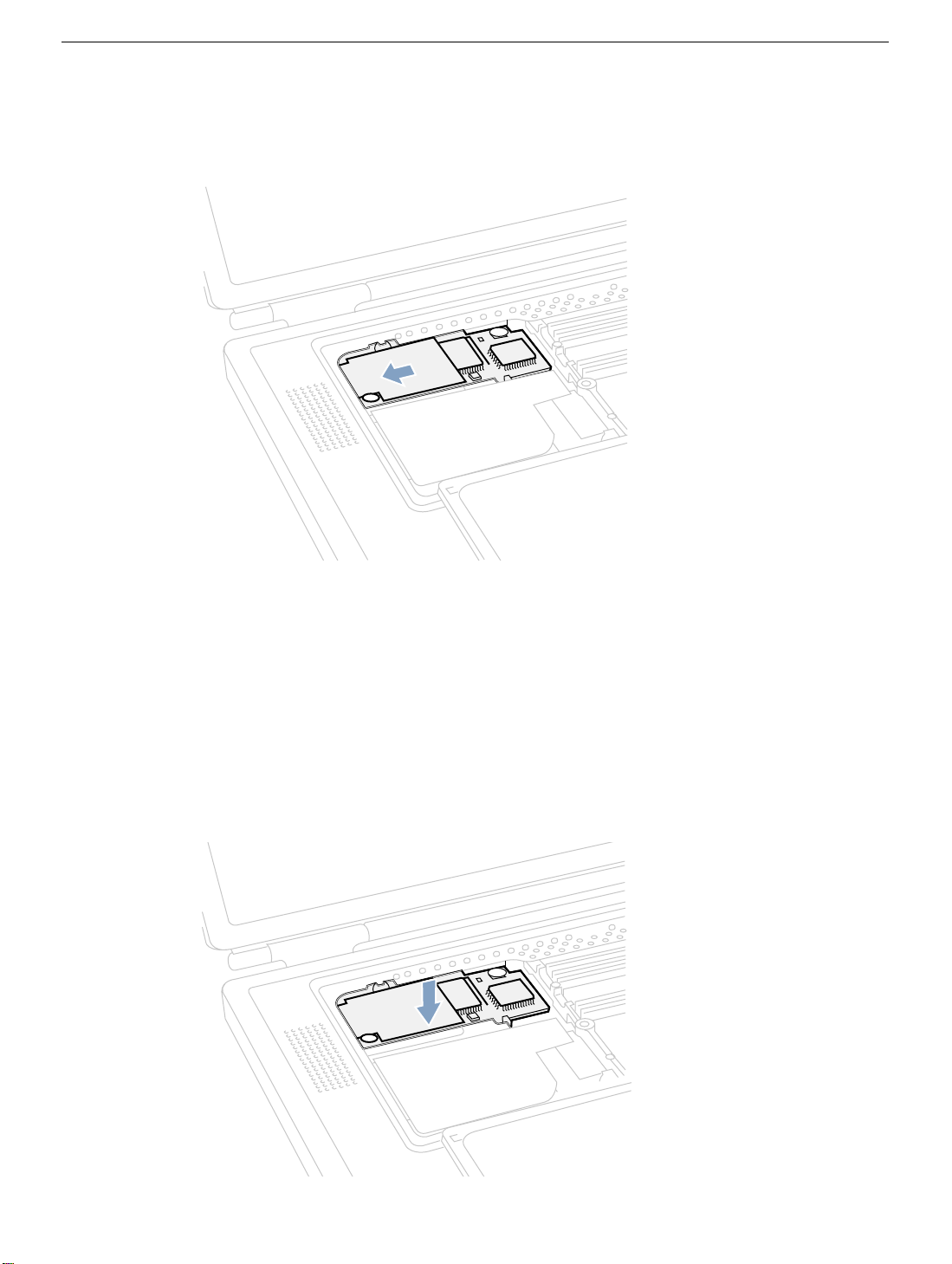
2. Carefully guide the cable into the space under the edge of the keyboard opening and
lay the modem into the modem opening
Figure 11
3. Line up the hexnut screw hole, in the left front corner of the modem, with the hole in
the logic board. The modem should lie flat.
(Figure 11)
.
Note:
Visually verify that the modem connector cable is still attached.
4. Press down on the front edge of the modem, slightly left of center, to firmly connect it
to the logic board
Note:
You may need to maneuver the modem around slightly until you feel the
connectors match up.
Figure 12
(Figure 12)
.
PowerBook G4 (Gigabit Ethernet) Modem -
7
Page 24
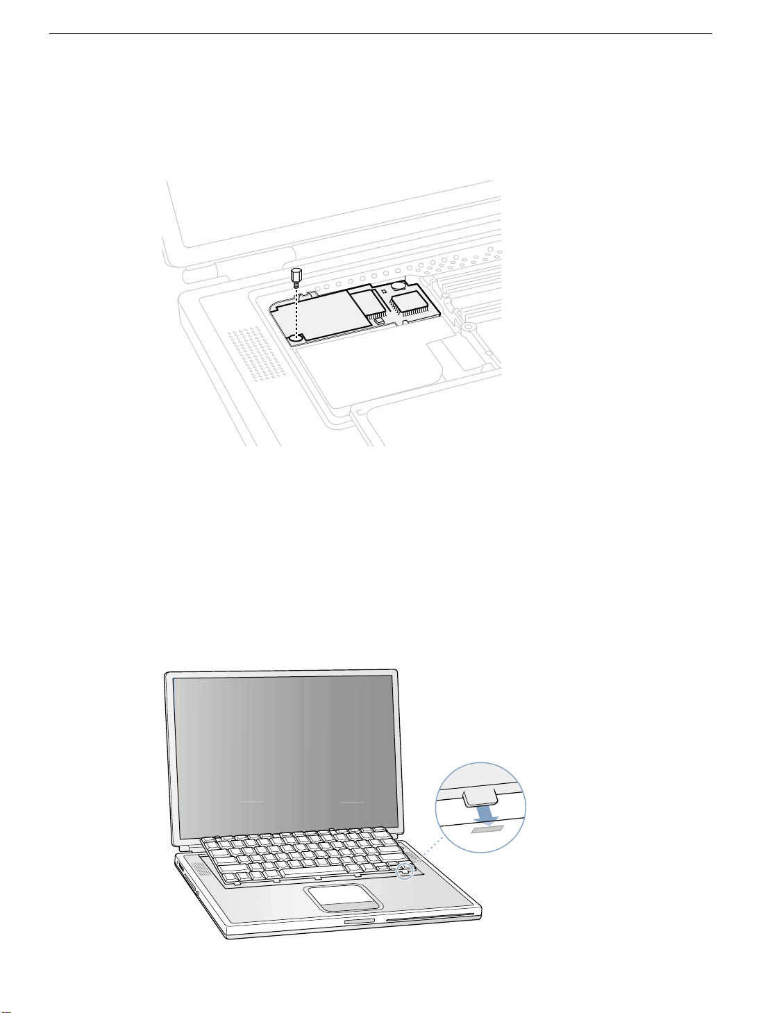
5. Install the hexnut screw.
Note:
It may be helpful to use a finger tip to hold the top of the screw straight and
steady while turning the screw.
Figure 13
(Figure 13)
Closing the Computer
1. Flip the keyboard back toward the keyboard opening in the case.
2. Hold the keyboard at an angle abov e the k eyboard opening, and insert the tabs on the
bottom edge of the keyboard into the slots below the edge of the opening.
Important:
against the edge of the opening.
Figure 14
Make sure that all the tabs are seated and that the keyboard rests flush
(Figure 14)
3. Lay the keyboard flat into the keyboard opening.
PowerBook G4 (Gigabit Ethernet) Modem -
8
Page 25
4. Pull down on the keyboard release tabs and then press do wn on the top portion of the
keyboard.
(Figure 15)
Figure 15
®
5. Release the tabs to secure the keyboard in place.
6. Close the display and turn the PowerBook over.
7. Replace the battery into the battery compartment.
(Figure 16)
.
Important: Make sure that the battery locks securely into place and that the battery
latch is slid all the way into the locked position.
Figure 16
8. Reconnect the power cord and any other cables that w ere connected, and restart your
computer.
Warning: Never turn on your computer unless all of its internal and external
parts are in place and it is closed. Operating the computer when it is open or
missing parts can damage your computer or cause injury.
PowerBook G4 (Gigabit Ethernet) Modem -
9
Page 26

Replacing International Modems
After you have replaced a modem in Europe or Asia, open the software utility Modem
Country Selector and verify that the modem is set to the correct country. Modem Country
Selector is located in the Apple Extras folder on your hard drive or can be downloaded as
part of the Apple Modem Updater software bundle at http://asu.info.apple.com.
Apple Computer, Inc.
© 2001 Apple Computer, Inc. All rights reserved.
Under the copyright laws, this document ma y not be copied, in whole or in part, without the
written consent of Apple.
The Apple logo is a trademark of Apple Computer, Inc., registered in the U.S. and other
countries. Use of the “keyboard” Apple logo (Option-Shift-K) for commercial purposes
without the prior written consent of Apple may constitute trademark infringement and
unfair competition in violation of federal and state laws.
Every effort has been made to ensure that the information in this document is accurate.
Apple is not responsible for printing or clerical errors.
Apple Computer, Inc.
1 Infinite Loop
Cupertino, CA 95014-2084
USA
+ 1 408 996 1010
http://www.apple.com
Apple, the Apple logo, and PowerBook are trademarks of Apple Computer , Inc., registered
in the U.S. and other countries.
PowerBook G4 (Gigabit Ethernet) Modem -
10
Page 27

PowerBook G4 (Gigabit Ethernet)
Bottom Case
Replacement Instructions
Follow the instructions in this sheet carefully. Failure to follow these instructions could
damage your equipment and void its warranty.
Note:
Written and video instructions covering customer-installable parts are available at
http://www.info.apple.com/installparts/.
Warning: Sharp edges can exist inside your computer and on any parts being
removed or installed. Use caution to avoid injury. Keep small parts away from
children.
Tools Required
• Soft towel or cloth, larger than the PowerBook
• Torx T8 screwdriver (provided with bottom case)
Removing the Bottom Case
Warning: Always shut down your computer before opening it to avoid damaging its
internal components or causing injury. After you shut down the computer, the
internal components can be very hot. Let the computer cool down before
continuing.
1. Place your computer on a clean, flat surface.
2. Shut down your computer and wait thirty minutes before continuing.
3. Disconnect the power cord and any other cables connected to the computer.
Page 28
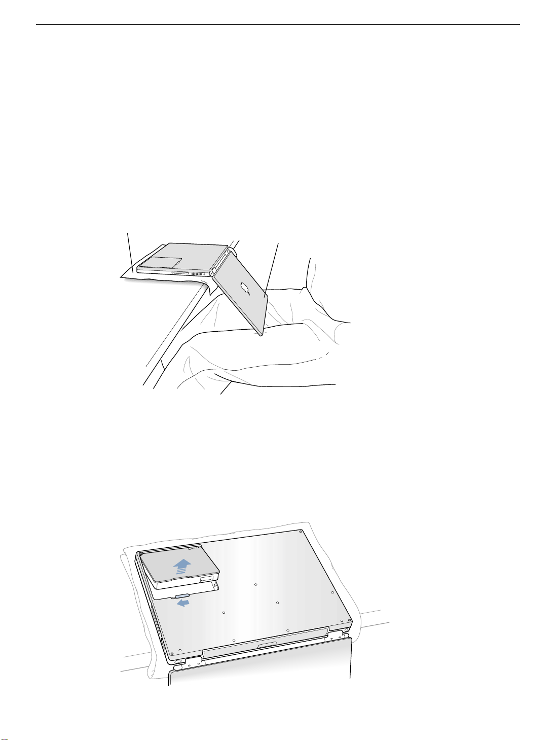
4. Place a towel or soft cloth on a table in front of you.
(Figure 1A)
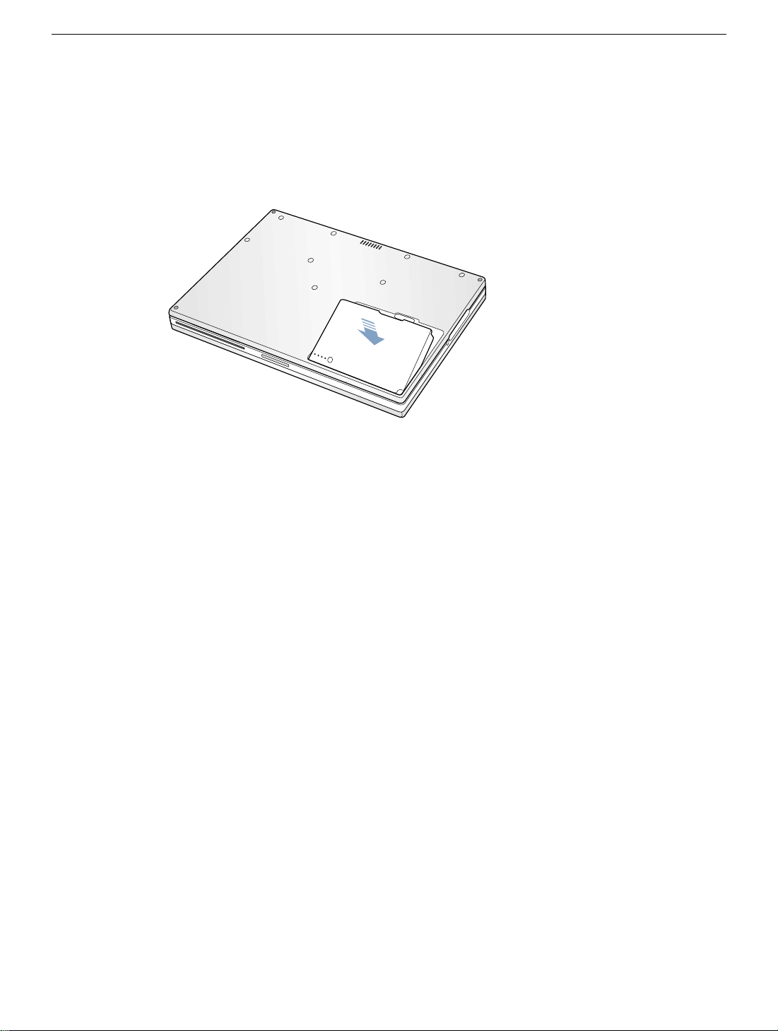
The towel or cloth will protect the keyboard and display area of the PowerBook when
you flip it over to remove the battery and bottom case. Make sure it covers an area
large enough for your PowerBook and that it hangs over the edge of the table.
5. With the display open at an angle greater than 90 degrees, carefully flip the
Pow erBook o v er and la y it flat, fully on the tab le . Make sure the display hangs o v er the
edge of the table and rests lightly on your lap.
(Figure 1B)
Important:
Do not open the display farther than the angle shown.
Figure 1
A
B
6. Remove the battery by sliding the battery latch to the left. Mak e sure to return the latch
fully to the right.
(Figure 2)
Removing the battery will prevent you from accidentally turning on the computer.
Warning: Removing the battery before shutting down your computer may
result in data loss.
Figure 2
PowerBook G4 (Gigabit Ethernet) Bottom Case -
2
Page 29
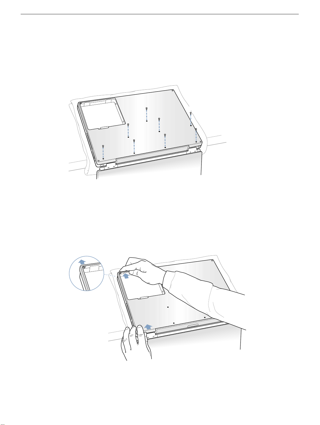
7. Using the Torx T8 screwdriver, remove the eight bottom case screws in the order
shown in the illustration.
(Figure 3)
Important:
To avoid damaging the case, be careful that the screwdriver tip does not
slip out of the screw head during removal.
Figure 3
1
2
6
Note:
The following three steps explain how to remove the bottom case by disengaging it
7
3
8
4
5
at the left and right sides and then carefully pivoting it forward.
Important:
During this procedure, do not push on the rubber feet of the bottom case.
8. Place your hands on the bottom case as shown
until the left side releases.
Figure 4
(Figure 4)
and push away from you
PowerBook G4 (Gigabit Ethernet) Bottom Case -
3
Page 30
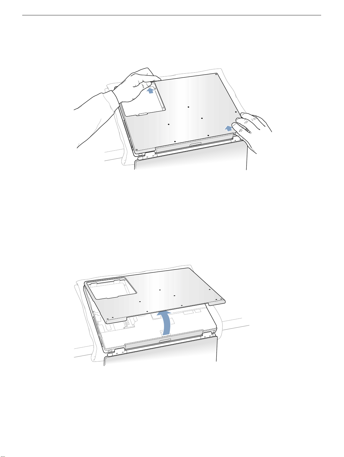
9. Place your hands on the bottom case as shown
until the right side releases.
Figure 5
10. When both sides have released, lift up on the edge of the bottom case that is closest
to you; carefully and ev enly piv ot it ov er the front edge of the computer until it releases.
(Figure 6)
Important: Do not twist the bottom case from side to side. Slide the case forward
completely before lifting it up. If you feel any resistance when lifting the bottom case,
double-check to make sure the case is slid all the way forward and releases from the
front edge.
(Figure 5)
and push away from you
Figure 6
PowerBook G4 (Gigabit Ethernet) Bottom Case -
4
Page 31

Installing the Replacement Bottom Case
1. To install the new bottom case, place it over the bottom of the computer in the same
orientation as the original bottom case.
2. Align the notches on the right and left sides of the case (some of these can be viewed
through the battery opening). Then press down and toward you slightly to secure the
case.
Important: Make sure that the seams between the bottom case and the frame are
closed. Verify that the case lies flat and fits properly around the battery latch and that
the alignment tab that protrudes on the underside of the bottom case, shown in the
illustration
Note:
battery compartment opening, near the latch, and on the front and back outside
edges of the case.
3. Check that the eight screw holes on the case align with the holes on the computer.
(Figure 7A)
, is seated properly.
To help with alignment, apply pressure to the bottom case at the back of the
4. Replace the eight screws in the order shown in the illustration
overtighten the screws or damage could result.
Note:
The screws must go in straight and easily; if they do not, readjust the bottom
case for proper alignment.
Important:
To avoid damaging the case, be careful that the screwdriver tip does not
slip out of the screw head during tightening.
Figure 7
8
A
7
1
3
6
2
5
4
(Figure 7)
. Do not
PowerBook G4 (Gigabit Ethernet) Bottom Case -
5
Page 32

5. Replace the battery.
(Figure 8)
Important: Make sure that the battery locks securely into place and that the battery
latch is slid all the way into the locked position.
Figure 8
6. Turn the computer over so that the optical drive slot faces you. Verify that the bottom
case is flush with the front edge of the slot. If the case is slightly bowed and there is a
gap near the center of the slot, carefully pull the bottom edge of the slot until it clicks
into place and becomes flush with the bottom case.
(Figure 9)
Figure 9
®
PowerBook G4 (Gigabit Ethernet) Bottom Case -
6
Page 33

7. Reconnect the power cord and any other cables that w ere connected, and restart your
computer.
Warning: Never turn on your computer unless all of its internal and external
parts are in place and it is closed. Operating the computer when it is open or
missing parts can damage your computer or cause injury.
Apple Computer, Inc.
© 2001 Apple Computer, Inc. All rights reserved.
Under the copyright laws, this document ma y not be copied, in whole or in part, without the
written consent of Apple.
The Apple logo is a trademark of Apple Computer, Inc., registered in the U.S. and other
countries. Use of the “keyboard” Apple logo (Option-Shift-K) for commercial purposes
without the prior written consent of Apple may constitute trademark infringement and
unfair competition in violation of federal and state laws.
Every effort has been made to ensure that the information in this document is accurate.
Apple is not responsible for printing or clerical errors.
Apple Computer, Inc.
1 Infinite Loop
Cupertino, CA 95014-2084
USA
+ 1 408 996 1010
http://www.apple.com
Apple, the Apple logo, and PowerBook are trademarks of Apple Computer, Inc., registered
in the U.S. and other countries.
PowerBook G4 (Gigabit Ethernet) Bottom Case -
7
Page 34

PowerBook G4 (Gigabit Ethernet)
AirPort Card
Replacement Instructions
Follow the instructions in this sheet carefully. Failure to follow these instructions could
damage your equipment and void its warranty.
Note:
Written and video instructions covering customer-installable parts are available at
http://www.info.apple.com/installparts/.
Warning: Sharp edges can exist inside your computer and on any parts being
removed or installed. Use caution to avoid injury. Keep small parts away from
children.
Tools Required
• Soft towel or cloth, larger than the PowerBook
• Torx T8 screwdriver
Opening the Computer
Warning: Always shut down your computer before opening it to avoid damaging its
internal components or causing injury. After you shut down the computer, the
internal components can be very hot. Let the computer cool down before
continuing.
To access the AirPort Card, you must first remove the battery and bottom case.
1. Place your computer on a clean, flat surface.
2. Shut down your computer and wait thirty minutes before continuing.
3. Disconnect the power cord and any other cables connected to the computer.
Page 35

4. Place a towel or soft cloth on a table in front of you.
(Figure 1A)
The towel or cloth will protect the keyboard and display area of the PowerBook when
you flip it over to remove the battery and bottom case. Make sure it covers an area
large enough for your PowerBook and that it hangs over the edge of the table.
5. With the display open at an angle greater than 90 degrees, carefully flip the
Pow erBook o v er and la y it flat, fully on the tab le . Make sure the display hangs over the
edge of the table and rests lightly on your lap.
(Figure 1B)
Important:
Do not open the display farther than the angle shown.
Figure 1
A
B
6. Remove the battery by sliding the battery latch to the left. Mak e sure to return the latch
fully to the right.
(Figure 2)
Removing the battery will prevent you from accidentally turning on the computer.
Warning: Removing the battery before shutting down your computer may
result in data loss.
Figure 2
PowerBook G4 (Gigabit Ethernet) AirPort Card -
2
Page 36

7. Using a Torx T8 screwdriver, remove the eight bottom case screws in the order sho wn
in the illustration.
(Figure 3)
Important:
To avoid damaging the case, be careful that the screwdriver tip does not
slip out of the screw head during removal.
Figure 3
1
2
6
Note:
The following three steps explain how to remove the bottom case by disengaging it
7
3
8
4
5
at the left and right sides and then carefully pivoting it forward.
Important:
During this procedure, do not push on the rubber feet of the bottom case.
8. Place your hands on the bottom case as shown
until the left side releases.
Figure 4
(Figure 4)
and push away from you
PowerBook G4 (Gigabit Ethernet) AirPort Card -
3
Page 37

9. Place your hands on the bottom case as shown
until the right side releases.
Figure 5
10. When both sides have released, lift up on the edge of the bottom case that is closest
to you; carefully and ev enly piv ot it ov er the front edge of the computer until it releases.
(Figure 6)
Important: Do not twist the bottom case from side to side. Slide the case forward
completely before lifting it up. If you feel any resistance when lifting the bottom case,
double-check to make sure the case is slid all the way forward and releases from the
front edge.
(Figure 5)
and push away from you
Figure 6
PowerBook G4 (Gigabit Ethernet) AirPort Card -
4
Page 38

11. Touch the computer’s inside framework (a dull gray conductive composite material) to
discharge any static electricity, as shown.
(Figure 7)
Important:
touching the computer’s framework before you touch any parts or install any
components inside the computer. To avoid static electricity building back up in your
body, do not walk around the room until you have completed your installation and
closed the computer.
Figure 7
To avoid electrostatic discharge damage, always ground yourself by
PowerBook G4 (Gigabit Ethernet) AirPort Card -
5
Page 39

Removing the Installed AirPort Card
1. Pull back on the antenna clip
(Figure 8B)
2. Pull the card from the AirPort connector
3. Hold the AirPort Card with one hand and grasp the antenna cable connector with the
other. While being careful not to strain the antenna cable
connector straight out of the AirPort Card.
Figure 8
C
A
B
and allow the card to rise up slightly.
D
(Figure 8A)
to release the antenna cable connector
(Figure 8D)
.
(Figure 8C)
, firmly pull the
Important:
cable connector into its holder
slightly and away from the edge of the computer case. This prevents the cable from
interfering with the PC card slot, below, or getting pinched during reassembly.
Also, if the insertion end of the AirPort Card connector is rotated up, push it down into
the level position. This allows the bottom case to install properly.
If the AirPort Card is not being replaced right away, replace the antenna
(Figure 10B)
and pull the loop of the antenna cable up
Installing the Replacement AirPort Card
1. If the AirPort Card to be installed came with the AirPort adapter
the metal clip
(The adapter and metal clip are not used with your PowerBook.)
Figure 9
C
(Figure 9B)
B
and pull the AirPort Card
A
(Figure 9C)
(Figure 9A)
from the adapter.
, remove
PowerBook G4 (Gigabit Ethernet) AirPort Card -
6
Page 40

2. If necessary, pull the AirPort antenna cable connector
(Figure 10B)
.
Figure 10
B
A
(Figure 10A)
from its holder
3. Pull up the insertion end of the AirPort Card connector
(Figure 11A)
to raise it up
slightly, if it is not already up.
4. Position the AirPort Card
(Figure 11B)
with the AirPort ID numbers and bar code
facing up and slide the card into the connector . Make sure to slide the card all the way
in until the card is securely attached to the connector.
Figure 11
B
A
PowerBook G4 (Gigabit Ethernet) AirPort Card -
7
Page 41

5. Plug the antenna cable connector
below the plastic tab
(Figure 12B)
(Figure 12A)
into the port, which is located just
, on the end of the AirPort Card. Make sure the
connector is straight before inserting it into the card.
6. Push the AirPort Card down into its space until the antenna cable connector is
secured by the small antenna clip
(Figure 12C)
.
Important:
Route the antenna cable
(Figure 12D)
between the edge of the computer
and the AirPort Card. Verify that the cable is away from the edge of the computer so
that it will not be pinched during reassembly and that it does not sag down into the
PC card slot area (below the AirPort Card). Take up any extra cable by tucking it in
where shown
7. Fold the plastic tab
Note:
(Figure 12E)
(Figure 12B)
.
on the AirPort Card over the top of the card.
The plastic tab must be folded over the card during the installation of the
bottom case; otherwise you will not be able to securely attach the bottom case to the
computer.
Figure 12
E
B
D
C
A
PowerBook G4 (Gigabit Ethernet) AirPort Card -
8
Page 42

Closing the Computer
1. To replace the bottom case, place it over the bottom of the computer in the same
orientation as the original bottom case.
2. Align the notches on the right and left sides of the case (some of these can be viewed
through the battery opening). Then press down and toward you slightly to secure the
case.
Important: Make sure that the seams between the bottom case and the frame are
closed. Verify that the case lies flat and fits properly around the battery latch and that
the alignment tab that protrudes on the underside of the bottom case, shown in the
illustration
Note:
battery compartment opening, near the latch, and on the front and back outside
edges of the case.
3. Check that the eight screw holes on the case align with the holes on the computer.
(Figure 13A)
, is seated properly.
To help with alignment, apply pressure to the bottom case at the back of the
4. Replace the eight screws in the order shown in the illustration
overtighten the screws or damage could result.
Note:
The screws must go in straight and easily; if they do not, readjust the bottom
case for proper alignment.
Important:
To avoid damaging the case, be careful that the screwdriver tip does not
slip out of the screw head during tightening.
Figure 13
8
A
7
1
3
6
2
5
4
(Figure 13)
. Do not
PowerBook G4 (Gigabit Ethernet) AirPort Card -
9
Page 43

5. Replace the battery.
(Figure 14)
Important: Make sure that the battery locks securely into place and that the battery
latch is slid all the way into the locked position.
Figure 14
6. Turn the computer over so that the optical drive slot faces you. Verify that the bottom
case is flush with the front edge of the slot. If the case is slightly bowed and there is a
gap near the center of the slot, carefully pull the bottom edge of the slot until it clicks
into place and becomes flush with the bottom case.
(Figure 15)
Figure 15
®
PowerBook G4 (Gigabit Ethernet) AirPort Card -
10
Page 44

7. Reconnect the power cord and any other cables that w ere connected, and restart your
computer.
Warning: Never turn on your computer unless all of its internal and external
parts are in place and it is closed. Operating the computer when it is open or
missing parts can damage your computer or cause injury.
Apple Computer, Inc.
© 2001 Apple Computer, Inc. All rights reserved.
Under the copyright laws, this document ma y not be copied, in whole or in part, without the
written consent of Apple.
The Apple logo is a trademark of Apple Computer, Inc., registered in the U.S. and other
countries. Use of the “keyboard” Apple logo (Option-Shift-K) for commercial purposes
without the prior written consent of Apple may constitute trademark infringement and
unfair competition in violation of federal and state laws.
Every effort has been made to ensure that the information in this document is accurate.
Apple is not responsible for printing or clerical errors.
Apple Computer, Inc.
1 Infinite Loop
Cupertino, CA 95014-2084
USA
+ 1 408 996 1010
http://www.apple.com
Apple, the Apple logo, and PowerBook are trademarks of Apple Computer, Inc., registered
in the U.S. and other countries.
AirPort is a trademark of Apple Computer, Inc.
PowerBook G4 (Gigabit Ethernet) AirPort Card -
11
Page 45

PowerBook G4 (Gigabit Ethernet)
Hard Drive
Replacement Instructions
Follow the instructions in this sheet carefully. Failure to follow these instructions could
damage your equipment and void its warranty.
Note:
Written and video instructions covering customer-installable parts are available at
http://www.info.apple.com/installparts/.
Warning: Sharp edges can exist inside your computer and on any parts being
removed or installed. Use caution to avoid injury. Keep small parts away from
children.
Tools Required
• Soft towel or cloth, larger than the PowerBook
• Torx T8 screwdriver (provided with hard drive)
Backing Up Your Data
Warning: Before replacing your hard drive, make sure you back up all data on the
drive.
Opening the Computer
Warning: Always shut down your computer before opening it to avoid damaging its
internal components or causing injury. After you shut down the computer, the
internal components can be very hot. Let the computer cool down before
continuing.
To access the hard drive, you must first remove the battery and bottom case.
1. Place your computer on a clean, flat surface.
2. Shut down your computer and wait thirty minutes before continuing.
3. Disconnect the power cord and any other cables connected to the computer.
073-0633 Rev. A
Page 46

4. Place a towel or soft cloth on a table in front of you.
(Figure 1A)
The towel or cloth will protect the keyboard and display area of the PowerBook when
you flip it over to remove the battery and bottom case. Make sure it covers an area
large enough for your PowerBook and that it hangs over the edge of the table.
5. With the display open at an angle greater than 90 degrees, carefully flip the
Pow erBook o v er and la y it flat, fully on the tab le . Make sure the display hangs over the
edge of the table and rests lightly on your lap.
(Figure 1B)
Important:
Do not open the display farther than the angle shown.
Figure 1
A
B
6. Remove the battery by sliding the battery latch to the left. Mak e sure to return the latch
fully to the right.
(Figure 2)
Removing the battery will prevent you from accidentally turning on the computer.
Warning: Removing the battery before shutting down your computer may
result in data loss.
Figure 2
PowerBook G4 (Gigabit Ethernet) Hard Drive -
2
Page 47

7. Using a Torx T8 screwdriver, remove the eight bottom case screws in the order sho wn
in the illustration.
(Figure 3)
Important:
To avoid damaging the case, be careful that the screwdriver tip does not
slip out of the screw head during removal.
Figure 3
1
2
6
Note:
The following three steps explain how to remove the bottom case by disengaging it
7
3
8
4
5
at the left and right sides and then carefully pivoting it forward.
Important:
During this procedure, do not push on the rubber feet of the bottom case.
8. Place your hands on the bottom case as shown
until the left side releases.
Figure 4
(Figure 4)
and push away from you
PowerBook G4 (Gigabit Ethernet) Hard Drive -
3
Page 48

9. Place your hands on the bottom case as shown
until the right side releases.
Figure 5
10. When both sides have released, lift up on the edge of the bottom case that is closest
to you; carefully and ev enly piv ot it ov er the front edge of the computer until it releases.
(Figure 6)
Important: Do not twist the bottom case from side to side. Slide the case forward
completely before lifting it up. If you feel any resistance when lifting the bottom case,
double-check to make sure the case is slid all the way forward and releases from the
front edge.
(Figure 5)
and push away from you
Figure 6
PowerBook G4 (Gigabit Ethernet) Hard Drive -
4
Page 49

11. Touch the computer’s inside framework (a dull gray conductive composite material) to
discharge any static electricity, as shown.
(Figure 7)
Important:
touching the computer’s framework before you touch any parts or install any
components inside the computer. To avoid static electricity building back up in your
body, do not walk around the room until you have completed your installation and
closed the computer.
Figure 7
To avoid electrostatic discharge damage, always ground yourself by
PowerBook G4 (Gigabit Ethernet) Hard Drive -
5
Page 50

Removing the Installed Hard Drive
1. With your fingers, carefully pry up the hard drive cable connector
sides to disconnect it from the logic board. You may need to pry one side, then the
other, in a rocking motion.
Figure 8
2. With a Torx T8 screwdriver, remove the two screws
drive to the mounting bracket and then gently remove the hard drive.
Important:
Do not pull on the connector cable or use the cable as a handle.
(Figure 9)
(Figure 8)
that secure the hard
at its
Figure 9
Note:
There are four rubber stoppers on the hard drive that fit over screws (two on
each side). Remove any that may have fallen off or that remain in the holes in the
mounting bracket inside the computer.
3. Replace the screws and rubber stoppers back onto the removed hard drive.
PowerBook G4 (Gigabit Ethernet) Hard Drive -
6
Page 51

Installing the Replacement Hard Drive
Warning: To avoid potential injury, avoid touching or brushing against the thin strip
of metal that extends up from the hard drive mounting bracket (Figure 10A).
Important:
1. With a Torx T8 screwdriver, remove the screw from the top of the hard drive mounting
bracket.
2. Carefully lift the mounting bracket up
battery bay tab
Warning: Lift the bracket just high enough to clear the battery bay tab. If you
lift the bracket higher than the tab you risk damaging the bracket, and such
damage is not covered by the limited warranty on your computer.
Figure 10
Avoid touching the optical drive as you perform this procedure.
(Figure 10B)
(Figure 10D)
B
A
(Figure 10C)
. The tab holds the bracket out of the way.
and gently bend it around the first
D
C
PowerBook G4 (Gigabit Ethernet) Hard Drive -
7
Page 52

3. Verify that the replacement hard drive has four screws
side, with four rubber stoppers
(Figure 11B)
attached.
(Figure 11A)
, two on each
Important:
If any screws or stoppers have come off, screw the screws back onto the
hard drive and then slide the rubber stoppers over them until they are against the
drive. Make sure that the Mylar sheath
(Figure 11C)
wraps around the bottom and
left and right sides of the drive, and that the rubber stoppers protrude through the
holes in the sheath along the sides.
Figure 11
C
B
A
4. Insert the right side of the drive first, until the rubber stoppers fit securely into the
holes in the bracket, and then insert the left side of the drive.
(Figure 12)
Figure 12
PowerBook G4 (Gigabit Ethernet) Hard Drive -
8
Page 53

5. Lift the mounting bracket
(Figure 13A)
over the battery bay tab and lower it to its
original position. Line up the rubber stoppers on the hard drive until the y fully seat into
the holes in the bracket.
Note:
To help with alignment, the Torx T8 screwdriver can be inserted into the screws
on the hard drive through the holes in the mounting bracket.
Important:
Verify that the bottom of the mounting bracket clears and seats behind a
thin metal ridge located along the bottom of the battery compartment.
6. Replace the screw
(Figure 13C)
in the top of the mounting bracket, being careful not
to overtighten it.
Figure 13
C
B
7. Connect the hard drive cable connector
(Figure 14)
to the logic board.
(Figure 13B)
A
Figure 14
PowerBook G4 (Gigabit Ethernet) Hard Drive -
9
Page 54

Closing the Computer
1. To replace the bottom case, place it over the bottom of the computer in the same
orientation as the original bottom case.
2. Align the notches on the right and left sides of the case (some of these can be viewed
through the battery opening). Then press down and toward you slightly to secure the
case.
Important: Make sure that the seams between the bottom case and the frame are
closed. Verify that the case lies flat and fits properly around the battery latch and that
the alignment tab that protrudes on the underside of the bottom case, shown in the
illustration
Note:
battery compartment opening, near the latch, and on the front and back outside
edges of the case.
3. Check that the eight screw holes on the case align with the holes on the computer.
(Figure 15A)
, is seated properly.
To help with alignment, apply pressure to the bottom case at the back of the
4. Replace the eight screws in the order shown in the illustration
overtighten the screws or damage could result.
Note:
The screws must go in straight and easily; if they do not, readjust the bottom
case for proper alignment.
Important:
To avoid damaging the case, be careful that the screwdriver tip does not
slip out of the screw head during tightening.
Figure 15
8
A
7
1
3
6
2
5
4
(Figure 15)
. Do not
PowerBook G4 (Gigabit Ethernet) Hard Drive -
10
Page 55

5. Replace the battery.
(Figure 16)
Important: Make sure that the battery locks securely into place and that the battery
latch is slid all the way into the locked position.
Figure 16
6. Turn the computer over so that the optical drive slot faces you. Verify that the bottom
case is flush with the front edge of the slot. If the case is slightly bowed and there is a
gap near the center of the slot, carefully pull the bottom edge of the slot until it clicks
into place and becomes flush with the bottom case.
(Figure 17)
Figure 17
®
PowerBook G4 (Gigabit Ethernet) Hard Drive -
11
Page 56

7. Reconnect the power cord and any other cables that w ere connected, and restart your
computer.
Warning: Never turn on your computer unless all of its internal and external
parts are in place and it is closed. Operating the computer when it is open or
missing parts can damage your computer or cause injury.
8. Restore the data from your backup to the new drive.
9. Check the operation of the optical drive. If the hard drive is installed incorrectly, the
optical drive mechanism might not spin correctly and will result in mechanical noise
when playing a disc.
Apple Computer, Inc.
© 2001 Apple Computer, Inc. All rights reserved.
Under the copyright laws, this document ma y not be copied, in whole or in part, without the
written consent of Apple.
The Apple logo is a trademark of Apple Computer, Inc., registered in the U.S. and other
countries. Use of the “keyboard” Apple logo (Option-Shift-K) for commercial purposes
without the prior written consent of Apple may constitute trademark infringement and
unfair competition in violation of federal and state laws.
Every effort has been made to ensure that the information in this document is accurate.
Apple is not responsible for printing or clerical errors.
Apple Computer, Inc.
1 Infinite Loop
Cupertino, CA 95014-2084
USA
+ 1 408 996 1010
http://www.apple.com
Apple, the Apple logo, and PowerBook are trademarks of Apple Computer, Inc., registered
in the U.S. and other countries.
PowerBook G4 (Gigabit Ethernet) Hard Drive -
12
Page 57

PowerBook G4 (Gigabit Ethernet)
DVD-ROM Optical Drive
Replacement Instructions
The following instructions explain how to replace the DVD-ROM optical drive in the
PowerBook G4 (Gigabit Ethernet) computer.
Note:
Depending on the configuration of a customer’s computer, the optical drive can be
a CD-RW drive, a DVD-ROM drive, or a combination CD-RW/DVD-ROM drive.
Tools
• Soft towel or cloth, larger than the PowerBook
• Black stick (or other nonconductive nylon or plastic tool)
Preliminary Steps
Before you begin, remove the following:
• Battery
• Keyboard
• Bottom case
©
2001 Apple Computer, Inc. All rights reserved.
Updated: 2001-12-17
Page 58

Procedure
1. With the computer open and sitting upright, use a black stick to pry up the EMI clip
from the rib frame as shown. Reserve the clip for installation of the replacement drive.
2.
Important:
computer. Some components could become loose and fall out.
With the bottom case removed, be careful when turning over the
Turn over the computer and carefully pry up the DVD-ROM drive cable connector to
disconnect it from the logic board.
Note:
If tape is covering the cable connector, carefully peel the tape back to expose
the connector. Reserve the tape for application on the replacement drive connector.
PowerBook G4 (Gigabit Ethernet) DVD-ROM Optical Drive -
2
Page 59

3. Locate the metal spacer that fits between the drive and the front bezel.
4. Remove the spacer by flexing the front bezel out while pulling up on the hinged metal
spacer.
Note: When installing the replacement drive, insert the hooks on the metal spacer
into the drive chassis, as shown.
PowerBook G4 (Gigabit Ethernet) DVD-ROM Optical Drive -
3
Page 60

5.
Important:
corners of the drive as shown by the highlighted safe areas.
6. Gently pull up on the outer side of the drive to remove it.
To prevent damage to the optical drive, handle the drive only by the
Note:
There are four rubber stoppers (two on each side) on the DVD-ROM drive that
fit over screws. Remove any that may have fallen off inside the computer.
PowerBook G4 (Gigabit Ethernet) DVD-ROM Optical Drive -
4
Page 61

7.
Important:
are in the correct locations. There are three types of rubber stoppers on the drive. The
outer side of the drive has two identical rubber caps that completely hide the screws
beneath them. The inner side of the drive has two different stoppers:
• Flat rubber ring over the screw closest to the hard drive
• Raised rubber ring over the screw closest to the logic board
Before installing the replacement drive, ensure that the rubber stoppers
When installing the replacement drive, first insert the stoppers on the inner side of the
drive into the openings on the rib frame. Then while holding the inner side of the drive
in place, carefully guide the rubber stoppers on the outer side of the drive past the
edge of the rib frame.
PowerBook G4 (Gigabit Ethernet) DVD-ROM Optical Drive -
5
Page 62

Important: Verify that the DVD-ROM drive cable does not get caught on the rib
frame as the drive is lowered into place. When the rubber stoppers are inserted, push
down on the side. Press at all four corners of the drive to verify that it rests flat and is
secure.
8. Reassemble and test the computer.
Important: Check the operation of the optical drive. If the drive is installed
incorrectly, the optical drive mechanism might not spin correctly and will result in
mechanical noise when playing a disc.
PowerBook G4 (Gigabit Ethernet) DVD-ROM Optical Drive -
6
Page 63

PowerBook G4 (Gigabit Ethernet)
CD-RW Optical Drive
Replacement Instructions
The following instructions explain how to replace the CD-RW optical drive in the
PowerBook G4 (Gigabit Ethernet) computer.
Note:
Depending on the configuration of a customer’s computer, the optical drive can be
a CD-RW drive, a DVD-ROM drive, or a combination CD-RW/DVD-ROM drive.
Tools
• Soft towel or cloth, larger than the PowerBook
• Black stick (or other nonconductive nylon or plastic tool)
Preliminary Steps
Before you begin, remove the following:
• Battery
• Keyboard
• Bottom case
©
2001 Apple Computer, Inc. All rights reserved.
Updated: 2001-12-17
Page 64

Procedure
1. With the computer open, slide the EMI clip off the rib frame as shown. Reserve the clip
for installation of the replacement drive.
2.
Important:
computer. Some components could become loose and fall out.
With the bottom case removed, be careful when turning over the
Turn over the computer and carefully pry up the CD-RW drive cable connector to
disconnect it from the logic board.
Note:
If tape is covering the cable connector, carefully peel the tape back to expose
the connector. Reserve the tape for application on the replacement drive connector.
PowerBook G4 (Gigabit Ethernet) CD-RW Optical Drive -
2
Page 65

3.
Warning: To prevent damage to the optical drive, handle the drive only by the
corners. Do not press on the body of the drive.
Gently pull up on the outer corners of the drive to remove it.
Note:
There are four rubber stoppers (two on each side) on the DVD-ROM drive that
fit over metal posts at the corners of the drive. Remove any that may have fallen off
inside the computer.
PowerBook G4 (Gigabit Ethernet) CD-RW Optical Drive -
3
Page 66

4.
Important:
are in the correct locations. There are three types of rubber stoppers on the drive. The
inner side of the drive has two different stoppers:
• Flat rubber ring fits over the post closest to the hard drive
• Raised rubber ring fits over the post closest to the logic board
The outer side of the drive has two identical rubber caps that completely hide the
posts beneath them.
Before installing the replacement drive, ensure that the rubber stoppers
PowerBook G4 (Gigabit Ethernet) CD-RW Optical Drive -
4
Page 67

5.
Warning: To prevent damage to the optical drive, handle the drive only by the
corners. Do not press on the body of the drive.
When installing the replacement drive, first insert the stoppers on the inner side of the
drive into the openings on the rib frame. Then while holding the inner side of the drive
in place, carefully guide the rubber stoppers on the outer side of the drive past the
edge of the rib frame.
Important: When the rubber stoppers are inserted, push down on all four corners of
the drive to verify that the drive is level and secure.
6. Reassemble and test the computer.
7.
Important:
the optical drive mechanism might not spin correctly and will result in mechanical
noise when playing a disc.
Check the operation of the optical drive. If the drive is installed incorrectly,
PowerBook G4 (Gigabit Ethernet) CD-RW Optical Drive -
5
Page 68

PowerBook G4 (Gigabit Ethernet)
Combination CD-RW/DVD-ROM Optical Drive
Replacement Instructions
The following instructions explain how to replace the combination CD-RW/DVD-ROM
optical drive in the PowerBook G4 (Gigabit Ethernet) computer.
Note:
Depending on the configuration of a customer’s computer, the optical drive can be
a CD-RW drive, a DVD-ROM drive, or a combination CD-RW/DVD-ROM drive.
Replacement Note:
ROM drives look alike. To identify the type of optical drive, check the model number on the
drive label:
• CW-7122 identifies a CD-RW drive
• CW-8121-C identifies a combination CD-RW/DVD-ROM drive
For this computer, CD-RW drives and combination CD-RW/DVD-
Tools
• Soft towel or cloth, larger than the PowerBook
• Black stick (or other nonconductive nylon or plastic tool)
Preliminary Steps
Before you begin, remove the following:
• Battery
• Keyboard
• Bottom case
©
2001 Apple Computer, Inc. All rights reserved.
Updated: 2001-12-17
Page 69

Procedure
1. With the computer open and the keyboard opening tilted up, slide the EMI clip off the
rib frame as shown. Set aside the clip for installation of the replacement drive.
2. When installing the replacement drive, ensure that the flex cable folds over the rib
frame before you install the EMI clip.
PowerBook G4 (Gigabit Ethernet) Combination CD-RW/DVD-ROM Optical Drive -
2
Page 70

3.
Important:
computer. Some components could become loose and fall out.
Turn over the computer and carefully pry up the optical drive cable connector to
disconnect it from the logic board.
Note:
the connector. Reserve the tape for application on the replacement drive connector.
With the bottom case removed, be careful when turning over the
If tape is covering the cable connector, carefully peel the tape back to expose
4.
Warning: To prevent damage to the optical drive, handle the drive only by the
corners. Do not press on the body of the drive.
Gently pull up on the outer corners of the drive to remove it.
Note:
There are four rubber stoppers (two on each side) on the drive that fit over
metal posts at the corners of the drive. Remove any that may have fallen off inside
the computer.
PowerBook G4 (Gigabit Ethernet) Combination CD-RW/DVD-ROM Optical Drive -
3
Page 71

5.
Important:
replace the felt strip with a new one before replacing the optical drive. Follow the
instructions below to replace the felt strip:
Locate the felt strip that came with the replacement drive. Before you remove the old
felt strip, note the alignment of the felt strip over the slot-load area in the inner top
case.
Peel off the felt strip from the inner top case. If there is any residual adhesive on the
top case, rub it away.
If you notice that the felt strip for the slot-load area is torn or damaged,
Apply the new felt strip to the slot-load area. Make sure the new felt strip lies flat. Use
a black stick to run the length of the slot to make sure that the felt strip does not block
any of the slot.
Note: Following are the differences among the felt strips for the optical drives:
• For the DVD-ROM drive, the strip is rounded at both ends and has an eject hole.
• For the CD-RW drive and the combination drive, the felt strip is squared off at one
end and has no eject hole.
PowerBook G4 (Gigabit Ethernet) Combination CD-RW/DVD-ROM Optical Drive -
4
Page 72

6.
Important:
are in the correct locations. There are three types of rubber stoppers on the drive.
The inner side of the drive has two different stoppers:
• Flat rubber ring (A) fits over the post closest to the hard drive
• Raised rubber ring (B) fits over the post closest to the logic board
The outer side of the drive has two identical rubber caps (C) that completely hide the
posts beneath them.
Before installing the replacement drive, ensure that the rubber stoppers
PowerBook G4 (Gigabit Ethernet) Combination CD-RW/DVD-ROM Optical Drive -
5
Page 73

7.
Warning: To prevent damage to the optical drive, handle the drive only by the
corners. Do not press on the body of the drive.
When installing the replacement drive, first insert the stoppers on the inner side of the
drive into the openings on the rib frame. Then while holding the inner side of the drive
in place, carefully guide the rubber stoppers on the outer side of the drive past the
edge of the rib frame.
Important: When the rubber stoppers are inserted, push down on all four corners of
the drive to verify that the drive is level and secure.
PowerBook G4 (Gigabit Ethernet) Combination CD-RW/DVD-ROM Optical Drive -
6
Page 74

8. Reassemble and test the computer.
Important: Make sure the bottom case is installed incorrectly. If the slot-load area is
slightly bowed, carefully pull the bottom edge of the slot until it clicks into place and
becomes flush with the bottom case.
Important: Check the operation of the optical drive. If the drive is installed
incorrectly, the optical drive mechanism might not spin correctly and will result in
mechanical noise when playing a disc.
PowerBook G4 (Gigabit Ethernet) Combination CD-RW/DVD-ROM Optical Drive -
7
Page 75

PowerBook G4 (Gigabit Ethernet)
Backup Battery
Replacement Instructions
The following instructions explain ho w to replace the bac kup battery in the PowerBook G4
(Gigabit Ethernet) computer.
Tools
• Soft towel or cloth, larger than the PowerBook
• Black stick (or other nonconductive nylon or plastic tool)
Preliminary Steps
Before you begin, remove the following:
• Battery
• Keyboard
• Bottom case
• Optical drive
©
2001 Apple Computer, Inc. All rights reserved.
Updated: 2001-10-29
Page 76

Procedure
1. Disconnect the backup battery cable from the backup battery.
Note:
If the cable connector gets caught on the ridged area of the top case, use
a black stick to raise up the backup battery and then disconnect the cable.
2.
Note:
The backup battery is compressed between two thin plastic sheets. The battery
is held in place with adhesive on the lower plastic sheet.
Slide a black stick under and along the edge of the backup battery. Pry up the
backup battery so that the entire battery—including the lower plastic sheet—is
removed from the inner top case.
PowerBook G4 (Gigabit Ethernet) Backup Battery -
2
Page 77

3.
Warning: The ridged area of the top case is sharp.
If there is any adhesive left on the surface of the inner top case, use a black
stick to rub it away. Do not use solvents.
Note: When installing the replacement backup battery, make sure the inner top case
is clean and free of debris.
4. Peel off the cover sheet from the bottom surface of the replacement backup battery to
expose the adhesive.
5. When positioning the replacement backup battery on the inner top case, make sure
the battery fits within the ridged battery area of the inner top case.
6. Install the replacement backup battery, and reassemble and test the computer.
PowerBook G4 (Gigabit Ethernet) Backup Battery -
3
Page 78

PowerBook G4 (Gigabit Ethernet)
Logic Board
Replacement Instructions
The following instructions explain how to replace the logic board in the PowerBook G4
(Gigabit Ethernet) computer.
Tools
• Soft towel or cloth, larger than the PowerBook
• Torx T8 screwdriver
• Black stick (or other nonconductive plastic or nylon tool)
• Razor blade
• Needlenose pliers (optional)
Note:
To organize the screws you remove from the computer, use a tray with divided
compartments (such as a plastic ice cube tray).
Preliminary Steps
Before you begin, remove the following:
• Battery
• Keyboard
• Modem
• Bottom case
• AirPort Card (if installed)
©
2001 Apple Computer, Inc. All rights reserved.
Updated: 2001-10-29
Page 79

Procedure
1. With the computer open, remove the three identical Torx T8 screws that border the
memory area of the logic board.
2. Remove the smaller Torx T8 screw near the heat pipe.
3. Disconnect the PC card flex cable connector and the keyed battery connector.
Important:
connector may be tight. If necessary, use a black stick or needlenose pliers to loosen
one side of the connector and then the other side. Then insert the black stick under
the cables to pry up and disconnect the connector.
Note: When reassembling the computer, tuck down the battery cables so they do
not get in the way when the keyboard is installed.
If the battery connector has not been disconnected before, the keyed
PowerBook G4 (Gigabit Ethernet) Logic Board -
2
Page 80

4. Disconnect the shielded, 3-pin backup battery connector from the logic board.
PowerBook G4 (Gigabit Ethernet) Logic Board -
3
Page 81

5.
Important:
computer. Some components could become loose and fall out.
Warning: The thin cables connected to the LVDS (low voltage data signal)
connector are extremely delicate. Do not pull or pinch the LVDS cables. Be
especially careful when working near cables that attach to the display. If any of
these cables are damaged, the entire display module must be replaced.
Turn over the computer so the display rests lightly in your lap. At the left side of the
logic board, disconnect the two-pin sleep LED cable connector, the LVDS connector,
and the six-pin audio connector.
With the bottom case removed, be careful when turning over the
PowerBook G4 (Gigabit Ethernet) Logic Board -
4
Page 82

6. Disconnect the AirPort Card cage connector.
7. Remove the Torx T8 screw at the corner of the logic board.
Important: When installing the replacement logic board, install this screw first. This
screw helps the logic board align properly to the rib frame.
8. Disconnect the trackpad connector and the hard drive connector.
Note: If tape is covering the trackpad connector, reserve the tape for installation of
the replacement logic board.
9. Remove the two identical Torx T8 screws and their washers, located near the center of
the board.
Note: When reassembling the computer, do not overtighten the screws.
PowerBook G4 (Gigabit Ethernet) Logic Board -
5
Page 83

10.
Important:
computer. Some components could become loose and fall out.
Tilt up the computer so you can access the EMI clip that secures the optical drive flex
cable to the rib frame.
Note: For replacement, note that the flat side of the EMI clip holds the flex cable
secured to the rib frame.
Slide off the EMI clip, and reserve it for reassembly. Then place the computer back in
position, so that the display rests lightly in your lap.
With the bottom case removed, be careful when turning over the
PowerBook G4 (Gigabit Ethernet) Logic Board -
6
Page 84

11. At the right side of the board, as shown, remove the Kapton tape (reserve it for
reassembly) and disconnect
• optical drive connector
• inverter board connector
12. Remove the Kapton tape from the two-pin power switch connector at the right corner
of the logic board. Disconnect the two-pin connector.
PowerBook G4 (Gigabit Ethernet) Logic Board -
7
Page 85

13. Grasp the logic board near the AirPort Card carrier. Gently tilt up the board, being
careful where it catches on the back panel ports, integral mesh liner, and the
disconnected cables.
If necessary, open the panel door and press on the ports to free the logic board from
the back panel.
PowerBook G4 (Gigabit Ethernet) Logic Board -
8
Page 86

Note: When reassembling the computer, make sure the replacement logic board
ports align completely with the openings in the back panel.
Note: When positioning the replacement logic board into the computer, check that
cables and connectors do not get caught under the board. Tilt the logic board toward
the back panel, and place the following cables into the notches in the board:
• Power switch cable (reapply tape over the cable, if applicable)
• Backlight cable
• LVDS cable
• Audio cable
14. Remove existing memory cards from the logic board for installation on the
replacement logic board.
PowerBook G4 (Gigabit Ethernet) Logic Board -
9
Page 87

15. Remove the single Torx T6 screw from the metal bracket holding the infrared
communications board.
16. Remove the infrared communications board for installation on the replacement logic
board.
PowerBook G4 (Gigabit Ethernet) Logic Board -
10
Page 88

17. Make sure the top of the replacement logic board includes the following items. If not,
transfer these items from the original logic board to the replacement board:
• U-shaped shim between FireWire and Ethernet ports
• Rectangular plastic shim near keyboard connector
• Spongy mesh pads adhered to two USB ports, FireWire port, TV out port, and
headphone port
PowerBook G4 (Gigabit Ethernet) Logic Board -
11
Page 89

18. Make sure the underside of the replacement logic board includes the following items:
• Left and right plastic panels at ports
• AirPort Card carrier
• Adhesive foam strips
PowerBook G4 (Gigabit Ethernet) Logic Board -
12
Page 90

19. Check that the heat exchanger has two square thermal interface pads in place. If the
pads are missing or damaged, replace them.
20.
Important:
be placing the original logic board back in the computer, use a razor blade to gently
scrape away any residual thermal transfer material from the heat exchanger and the
microprocessor chip.
Warning: When scraping away the thermal transfer material from the
microprocessor chip, be careful not to nick the microprocessor chip.
Apply new thermal transfer material to the microprocessor chip as described in the
next step.
If you have removed the logic board to access another part, and you will
PowerBook G4 (Gigabit Ethernet) Logic Board -
13
Page 91

21. On the replacement logic board, center new thermal transfer material over the epoxy
cap on the microprocessor chip. Press it into place.
22. Install the replacement logic board, and reassemble and test the computer.
PowerBook G4 (Gigabit Ethernet) Logic Board -
14
Page 92

PowerBook G4 (Gigabit Ethernet)
Fan
Replacement Instructions
The following instructions explain how to replace the fan in the PowerBook G4 (Gigabit
Ethernet) computer.
Tools
• Soft towel or cloth, larger than the PowerBook
• Black stick (or other nonconductive nylon or plastic tool)
• Razor blade
• Needlenose pliers
Preliminary Steps
Before you begin, remove the following:
• Battery
• Keyboard
• Modem
• Bottom case
• AirPort Card (if installed)
• Logic Board
©
2001 Apple Computer, Inc. All rights reserved.
Updated: 2001-10-29
Page 93

Procedure
1. With the logic board removed from the computer, disconnect the fan connector from
the logic board.
2. Turn over the logic board, and locate the cone-shaped pin at the right corner of the
fan. Pull the rubber pin tight. Use a razor blade to cut through the rubber pin.
PowerBook G4 (Gigabit Ethernet) Fan -
2
Page 94

3. Turn over the logic board, and tilt up the fan to remove it completely from the logic
board.
Note: The fan is secured to the logic board by a spongy, rubber adhesive lining on
three sides of the bottom of the fan. If there is any adhesive stuck to the surface of
the logic board, remove it by rubbing it away. Do not use solvents.
4. When installing the replacement fan, first use a black stick to push the cone-shaped
rubber pin into the hole on the logic board. (If necessary , use needlenose pliers to pull
the rubber pin through to the other side of the logic board.) Then, peel away the
protective cover from the adhesive that lines the three sides of the fan. Align the fan
over the logic board opening and press the fan into place.
Note: If the cone-shaped rubber pin is too long, use a razor blade to cut the extra
length.
5. With the replacement fan installed securely and the fan connector connected to the
logic board, reassemble and test the computer.
PowerBook G4 (Gigabit Ethernet) Fan -
3
Page 95

PowerBook G4 (Gigabit Ethernet)
PC Card Cage
Replacement Instructions
The following instructions explain how to replace the PC card cage in the PowerBook G4
(Gigabit Ethernet) computer.
Tools
• Soft towel or cloth larger than the PowerBook
• Torx T8 screwdriver
Note:
To organize the screws you remove from the computer, use a tray with divided
compartments (such as a plastic ice cube tray).
Preliminary Steps
Before you begin, remove the following:
• Battery
• Keyboard
• Modem
• Bottom case
• AirPort Card (if installed)
• Logic board
©
2001 Apple Computer, Inc. All rights reserved.
Updated: 2001-10-29
Page 96

Procedure
1. With the computer on a soft cloth, remove the two screws that attach the PC card
cage to the rib frame. (The longer screw is next to the battery connector.)
2. Lift out the PC card cage, being careful where it can catch on the PC card eject button.
3. Check that the replacement PC card cage includes a clear plastic shim on the outer
frame near the PC card eject button. If the shim is not there , transf er the shim from the
old PC card cage to the replacement PC card cage.
PowerBook G4 (Gigabit Ethernet) PC Card Cage -
2
Page 97

4. When installing the replacement PC card cage, ensure that the metal flange that is
closest to the PC card eject button goes underneath the rib frame and metal liner at
the battery latch.
5. Install the replacement PC card cage, and reassemble and test the computer.
PowerBook G4 (Gigabit Ethernet) PC Card Cage -
3
Page 98

PowerBook G4 (Gigabit Ethernet)
Rib Frame and Heat Exchanger
Replacement Instructions
The following instructions explain how to replace the rib frame and the heat exchanger in
the PowerBook G4 (Gigabit Ethernet) computer.
Warning: Make sure you carefully follow these instructions, especially when
working near cables that attach to the display module. If any of the cables are
damaged, the entire display module must be replaced.
Tools
• Soft towel or cloth larger than the PowerBook
• Black stick (or other nonconductive nylon or plastic tool)
• Torx T8 screwdriver
• #1 Phillips screwdriver
• Torx T6 screwdriver
Note:
To organize the screws you remove from the computer, use a tray with divided
compartments (such as a plastic ice cube tray).
Preliminary Steps
Before you begin, remove the following:
• Battery
• Keyboard
• Modem
• Bottom case
• AirPort Card (if installed)
• Hard drive
• Optical drive
• Logic board
• PC card cage
©
2001 Apple Computer, Inc. All rights reserved.
Updated: 2001-10-29
Page 99

Procedure
1. With the computer on a soft cloth, remove the two identical screws from the top case.
2. Close the computer to an approximate 45-degree angle, and stand it on a soft cloth
with the clutch covers facing up.
3. Remove the four identical Torx T8 screws from the clutch covers (two screws on each
clutch cover).
4. Use a black stick to pry off the two clutch covers.
PowerBook G4 (Gigabit Ethernet) Rib Frame and Heat Exchanger -
2
Page 100

5. Open the computer so that the display rests in your lap and is protected by a soft
cloth.
6.
Warning: Be especially careful when working near cables that attach to the
display. If any of these cables are damaged, the entire display module must be
replaced.
Warning: At the left clutch, the wrapped cable connected to the LVDS (low
voltage data signal) connector is extremely delicate. Do not pull or pinch the
LVDS cable. Do not allow the screwdriver to touch the LVDS cable.
Locate the two large silver-colored screws. Gently move aside the LVDS cable so
you can access the screws.
Remove the two silver-colored Phillips screws from the left clutch. Notice that the
screw closest to the LVDS cable has a sloped screw head.
Important: When installing the replacement display, make sure the screw closest to
the LVDS cable is the screw with the sloped head.
PowerBook G4 (Gigabit Ethernet) Rib Frame and Heat Exchanger -
3
 Loading...