

Page 1

MainStage 3 Instruments
For OS X
Page 2

K Apple Inc.
Copyright © 2013 Apple Inc. All rights reserved.
Your rights to the software are governed by the accompanying
software license agreement. The owner or authorized user
of a valid copy of MainStage software may reproduce this
publication for the purpose of learning to use such software.
No part of this publication may be reproduced or transmitted
for commercial purposes, such as selling copies of this
publication or for providing paid for support services.
The Apple logo is a trademark of Apple Inc., registered in
the U.S. and other countries. Use of the “keyboard” Apple
logo (Shift-Option-K) for commercial purposes without the
prior written consent of Apple may constitute trademark
infringement and unfair competition in violation of federal and
state laws.
Every eort has been made to ensure that the information in
this manual is accurate. Apple is not responsible for printing or
clerical errors.
Because Apple frequently releases new versions and updates
to its system software, applications, and Internet sites, images
shown in this manual may be slightly dierent from what you
see on your screen.
Apple
1 Innite Loop
Cupertino, CA 95014
408-996-1010
www.apple.com
Apple, the Apple logo, Final Cut Pro, Finder, FireWire,
GarageBand, iMovie, iPad, iPhoto, iPod, iTunes, iTunes Store,
Jam Pack, Logic, Logic Pro, Mac, Macintosh, MainStage,
QuickTime, and Ultrabeat are trademarks of Apple Inc.,
registered in the U.S. and other countries.
IOS is a trademark or registered trademark of Cisco in the U.S.
and other countries and is used under license.
Other company and product names mentioned herein
are trademarks of their respective companies. Mention of
third-party products is for informational purposes only and
constitutes neither an endorsement nor a recommendation.
Apple assumes no responsibility with regard to the
performance or use of these products.
019-2556
Page 3

Contents
14 Chapter 1: Drum Kit Designer
14 Drum Kit Designer overview
15 Drum Kit Designer Edit panel
16 Use Drum Kit Designer
19 Drum Kit Designer extended parameters
20 Drum Kit Designer mappings
21 Chapter 2: ES1
21 ES1 overview
22 ES1 oscillator parameters
22 ES1 oscillator parameters overview
23 ES1 oscillator waveforms
23 Use the ES1 sub-oscillator
24 ES1 global parameters
25 ES1 lter parameters
25 ES1 lter parameters overview
26 Drive the ES1 lter to self-oscillate
27 ES1 amplier parameters
28 ES1 envelope parameters
28 ES1 envelope parameters overview
28 ES1 lter cuto envelope modulation
29 ES1 amplier envelope modulation
30 ES1 modulation
30 ES1 modulation parameters overview
30 Use the ES1 router
31 Use the ES1 LFO
32 Use the ES1 modulation envelope
33 ES1 MIDI controllers
34 Chapter 3: ES2
34 ES2 overview
35 ES2 interface
37 ES2 sound sources
37 ES2 oscillator parameters overview
38 ES2 basic oscillator waveforms
39 Use pulse width modulation in ES2
40 Use frequency modulation in ES2
41 Use ring modulation in ES2
42 Use ES2 Digiwaves
42 Use the ES2 noise generator
43 ES2 emulation of detuned analog oscillators
44 Stretch tuning in ES2
3
Page 4

45 Balance ES2 oscillator levels
45 ES2 oscillator start points
46 Synchronize ES2 oscillators
47 ES2 global parameters
47 Global parameters overview
48 Set the ES2 keyboard mode
48 Use unison and voices in ES2
49 Set the ES2 glide time
49 Set the ES2 pitch bend range
50 ES2 lter parameters
50 ES2 lter overview
51 ES2 lter conguration
51 Cross-fade between ES2 lters
53 ES2 Filter 1 modes
53 ES2 Filter 2 slopes
54 ES2 lter cuto and resonance
56 Overdrive ES2 lters
57 Modulate ES2’s Filter 2 Frequency
58 ES2 amplier parameters
58 Use ES2’s dynamic stage
58 Sine Level enhanced ES2 sounds
59 ES2 modulation
59 ES2 modulation overview
60 ES2 modulation router
64 ES2 LFOs
66 Use ES2 LFOs
67 ES2 envelopes
70 Use the Vector Envelope
71 Vector Envelope points, times, and loops
77 Use the Planar Pad
78 ES2 modulation target reference
84 ES2 modulation source reference
86 ES2 via modulation source reference
88 ES2 integrated eects processor
90 ES2 macro controls and controller assignments
90 ES2 macro and controller assignment overview
90 ES2 macro controls
91 Make ES2 controller assignments
92 ES2 extended parameters
92 Create random ES2 sound variations
92 Use ES2’s randomization parameters
93 Restriction of ES2 randomization
95 ES2 tutorials
95 Create ES2 sounds from scratch
106 Create ES2 sounds with templates
Contents 4
Page 5

111 Chapter 4: EFM1
111 EFM1 overview
113 EFM1 modulator and carrier parameters
113 Modulator and carrier overview
115 Set the EFM1 tuning ratio
115 Choose a dierent EFM1 modulator waveform
116 EFM1 modulation parameters
117 EFM1 global parameters
118 EFM1 output parameters
119 Create random EFM1 sounds
119 EFM1 extended parameters
120 EFM1 MIDI controller assignments
121 Chapter 5: ES E
121 ES E overview
122 ES E oscillator parameters
123 ES E LFO parameters
124 ES E lter parameters
125 ES E envelope parameters
125 ES E output parameters
126 Extended ES E parameters
127 Chapter 6: ES M
127 ES M overview
128 ES M oscillator parameters
129 ES M lter and lter envelope
130 ES M level envelope and output controls
130 Extended ES M parameters
131 Chapter 7: ES P
131 ES P overview
132 ES P oscillator parameters
133 ES P LFO parameters
134 ES P lter parameters
135 ES P envelope and level controls
136 Integrated ES P eects processor
136 Extended ES P parameters
Contents 5
Page 6

137 Chapter 8: EVOC 20 PolySynth
137 EVOC 20 PolySynth and vocoding
137 EVOC 20 PolySynth overview
138 Vocoder basics
139 EVOC 20 PolySynth interface
140 EVOC 20 PolySynth analysis parameters
141 EVOC 20 PolySynth (U/V) detection parameters
143 EVOC 20 PolySynth synthesis parameters
143 EVOC 20 PolySynth synthesis parameters overview
144 EVOC 20 PolySynth oscillator parameters
146 EVOC 20 PolySynth tuning and pitch parameters
147 EVOC 20 PolySynth lter parameters
147 EVOC 20 PolySynth envelope parameters
148 EVOC 20 PolySynth global parameters
149 EVOC 20 PolySynth formant lter
151 EVOC 20 PolySynth modulation parameters
152 EVOC 20 PolySynth output parameters
153 EVOC 20 PolySynth performance tips
153 Level and frequency tips
153 Tips to avoid sonic artifacts
154 Tips to enhance speech intelligibility
155 Vocoder history
156 EVOC 20 block diagram
157 Chapter 9: EXS24 mkII
157 EXS24 mkII overview
159 Sampler instruments
159 Sampler instruments overview
159 Sample storage locations
160 Manage sampler instruments
161 Use sampler instruments and settings
162 Import SoundFont2, DLS, and Gigasampler les
164 Convert audio regions to sampler instruments
165 Convert ReCycle les to sampler instruments
167 EXS24 mkII Parameter window
167 EXS24 mkII Parameter window overview
168 Sampler Instruments pop-up menu
171 EXS24 mkII global parameters
174 EXS24 mkII pitch parameters
176 EXS24 mkII lter parameters
178 EXS24 mkII output parameters
179 EXS24 mkII extended parameters
179 EXS24 mkII modulation overview
180 EXS24 mkII modulation router
184 EXS24 mkII LFOs
187 EXS24 mkII envelope overview
188 EXS24 mkII modulation reference
Contents 6
Page 7

192 EXS24 mkII Instrument Editor window
192 EXS24 mkII Instrument Editor overview
193 EXS24 mkII Zones and Groups view
195 Create instruments, zones, and groups
199 Edit EXS24 mkII zones and groups
211 Save, rename, and export EXS24 mkII instruments
212 Edit samples in the Logic Pro Audio File Editor
213 Use an external instrument editor with EXS24 mkII
214 EXS24 mkII preferences
217 EXS24 mkII memory management
219 Chapter 10: External Instrument
219 External Instrument overview
220 Use the External Instrument
221 Chapter 11: Klopfgeist
221 Klopfgeist parameters
223 Chapter 12: Retro Synth
223 Retro Synth overview
224 Retro Synth Analog oscillator controls
225 Retro Synth Sync oscillator controls
226 Retro Synth Table oscillator controls
227 Retro Synth FM oscillator controls
229 Retro Synth lter controls
231 Retro Synth amp and eect controls
232 Retro Synth modulation controls
232 Use Retro Synth modulation
233 Retro Synth Glide and Autobend
234 Retro Synth LFO and Vibrato
235 Retro Synth envelopes
236 Retro Synth global and controller settings
237 Retro Synth extended parameters
238 Chapter 13: Sculpture
238 Sculpture overview
240 Sculpture interface
241 Sculpture string parameters
241 Sculpture string overview
242 Sculpture Hide, Keyscale, and Release view
243 Sculpture’s basic Material Pad parameters
244 Use Sculpture’s Material Pad in Keyscale or Release view
245 Use Sculpture’s string parameter sliders
247 Sculpture objects parameters
247 Sculpture objects overview
248 Sculpture excite table (objects 1 and 2)
250 Sculpture disturb and damp table (objects 2 and 3)
252 Sculpture pickups parameters
252 Use Sculpture pickup parameters
253 Sculpture’s spread controls
254 Sculpture global parameters
Contents 7
Page 8

255 Sculpture amplitude envelope parameters
256 Use Sculpture’s Waveshaper
257 Sculpture lter parameters
258 Sculpture delay eect parameters
258 Sculpture delay eect overview
259 Sculpture’s Groove Pad (stereo)
260 Sculpture Body EQ parameters
260 Sculpture Body EQ overview
261 Use Sculpture’s Basic EQ model
262 Use Sculpture’s Body EQ models
263 Sculpture output parameters
263 Sculpture modulation controls
263 Sculpture modulation overview
264 Sculpture LFOs
268 Sculpture Vibrato parameters
269 Sculpture Jitter generators
270 Sculpture note-on random modulators
271 Sculpture velocity modulators
272 Use Controller A and B in Sculpture
272 Sculpture envelope parameters
280 Sculpture morph parameters
280 Sculpture morph overview
281 Use Sculpture’s Morph Pad
284 Use Sculpture’s Morph Envelope
289 Dene Sculpture MIDI controllers
290 Sculpture tutorials
290 Explore Sculpture
295 Create basic sounds in Sculpture
305 Advanced Sculpture tutorial: electric bass
323 Advanced Sculpture tutorial: synthesizer sounds
328 Chapter 14: Ultrabeat
328 Ultrabeat overview
329 Ultrabeat interface
330 Ultrabeat Assignment section
330 Ultrabeat Assignment section overview
331 Play and select Ultrabeat drum sounds
333 Name, swap, and copy Ultrabeat drum sounds
335 Import sounds and EXS instruments into Ultrabeat
337 Ultrabeat settings
338 Ultrabeat Synthesizer section overview
340 Ultrabeat sound sources
340 Ultrabeat oscillator overview
341 Ultrabeat oscillator 1 phase oscillator mode
342 Use Ultrabeat oscillator 1 FM mode
343 Use Ultrabeat oscillator 1 side chain mode
344 Use Ultrabeat oscillator 2 phase oscillator mode
345 Basic waveform characteristics
345 Use Ultrabeat oscillator 2 sample mode
Contents 8
Page 9

347 Use Ultrabeat oscillator 2 model mode
349 Ultrabeat ring modulator
349 Ultrabeat noise generator
351 Use Ultrabeat’s lter section
354 Ultrabeat distortion circuit
355 Ultrabeat Output section
355 Ultrabeat Output section overview
356 Adjust Ultrabeat’s two-band EQ
357 Ultrabeat pan and stereo spread
358 Ultrabeat voice volume control
359 Change Ultrabeat’s trigger mode
360 Ultrabeat modulation
360 Ultrabeat modulation overview
360 Mod and via modulations in Ultrabeat
362 Create a modulation routing in Ultrabeat
363 Assign Ultrabeat MIDI controllers A–D
364 Use Ultrabeat LFOs
367 Ultrabeat envelope overview
368 Ultrabeat envelope parameters
369 Use Ultrabeat’s modulation target display
370 Ultrabeat step sequencer
370 Ultrabeat step sequencer overview
370 Step sequencer basics
371 Ultrabeat step sequencer interface
371 Ultrabeat global sequencer controls
372 Ultrabeat pattern controls
373 Use Ultrabeat’s swing function
374 Ultrabeat Step grid
378 Automate parameters in Ultrabeat’s step sequencer
380 Export Ultrabeat patterns as MIDI regions
381 MIDI control of Ultrabeat’s step sequencer
382 Ultrabeat tutorials
382 Ultrabeat sound programming overview
383 Create Ultrabeat kick drums
387 Create Ultrabeat snare drums
392 Create Ultrabeat tonal percussion
392 Create Ultrabeat hi-hats and cymbals
393 Create metallic Ultrabeat sounds
393 Tips for extreme Ultrabeat sounds
Contents 9
Page 10

394 Chapter 15: Vintage B3
394 Vintage B3 overview
395 Vintage B3 Main window
395 Vintage B3 Main window overview
396 Vintage B3 draw bar controls
397 Vintage B3 Scanner Vibrato and Chorus
398 Vintage B3 Percussion eect
399 Use Vintage B3 preset keys
401 Set up Vintage B3 for your MIDI equipment
404 Vintage B3 Rotor Cabinet window
404 Vintage B3 Rotor Cabinet window overview
405 Advanced Cabinet parameters
406 Advanced Motor parameters
407 Advanced Brake parameters
408 Vintage B3 Microphone types
409 Vintage B3 Microphone parameters
410 Vintage B3 Options window
410 Vintage B3 Options window overview
410 Vintage B3 Master and Click controls
411 Vintage B3 Morph parameters
412 Use Vintage B3 Morph controls
413 Vintage B3 Eects window
413 Use Vintage B3 eects
414 Vintage B3 EQ
414 Vintage B3 Wah eect
416 Vintage B3 Distortion eect
416 Vintage B3 Reverb eect
417 Vintage B3 Expert window
417 Vintage B3 Expert window overview
418 Vintage B3 Pitch controls
419 Vintage B3 Sustain controls
419 Vintage B3 Condition controls
421 Vintage B3 Organ Model controls
422 Use a MIDI controller with Vintage B3
422 Choose a Vintage B3 MIDI control mode
422 Vintage B3 MIDI mode: Roland VK or Korg CX
424 Vintage B3 MIDI mode: Hammond Suzuki
425 Vintage B3 MIDI mode: Native Instruments B4D
427 Vintage B3 MIDI mode: Nord Electro
428 B3 and Leslie information
428 Additive synthesis with draw bars
429 The residual eect
429 Tonewheel sound generation
430 A brief Hammond history
431 The Leslie cabinet
Contents 10
Page 11

432 Chapter 16: Vintage Clav
432 Vintage Clav overview
433 Vintage Clav interface
434 Vintage Clav Main window
434 Vintage Clav Main window overview
435 Vintage Clav models
436 Vintage Clav model characteristics
437 Use Vintage Clav Pickup parameters
438 Use Vintage Clav Stereo Spread parameters
439 Vintage Clav Eects window
439 Vintage Clav Eects window overview
440 Vintage Clav Compressor eect
440 Vintage Clav Distortion eect
441 Vintage Clav Modulation eect
442 Vintage Clav Wah eect
443 Vintage Clav Details window
443 Vintage Clav Details window overview
443 Vintage Clav Excite and Click parameters
444 Vintage Clav String parameters
445 Vintage Clav Pitch parameters
446 Vintage Clav Misc parameters
447 Vintage Clav extended parameters
448 D6 Clavinet information
448 D6 Clavinet history
449 D6 Clavinet mechanical details
450 Chapter 17: Vintage Electric Piano
450 Vintage Electric Piano overview
451 Vintage Electric Piano interface
452 Vintage Electric Piano Eects window
452 Vintage Electric Piano EQ
453 Vintage Electric Piano Drive eect
453 Vintage Electric Piano Chorus eect
454 Vintage Electric Piano Phaser eect
455 Vintage Electric Piano Tremolo eect
456 Vintage Electric Piano Details window
456 Vintage Electric Piano model parameters
457 Vintage Electric Piano pitch parameters
458 Vintage Electric Piano extended parameters
459 Vintage Electric Piano emulations
459 Rhodes models
460 Hohner and Wurlitzer models
461 Vintage Electric Piano MIDI controllers
Contents 11
Page 12

462 Appendix A: Legacy instruments
462 Legacy instruments overview
462 Emulated instruments
462 Bass
462 Church Organ
463 Drum Kits
463 Electric Clav(inet)
463 Electric Piano
464 Guitar
464 Horns
464 Piano
464 Sound Eects
464 Strings
465 Tuned Percussion
465 Voice
465 Woodwind
465 Tonewheel Organ
466 Synthesizers
466 Analog Basic
466 Analog Mono
467 Analog Pad
467 Analog Swirl
468 Analog Sync
468 Digital Basic
469 Digital Mono
469 Digital Stepper
470 Hybrid Basic
471 Hybrid Morph
472 Appendix B: Synthesizer Basics
472 Synthesizer basics overview
473 Sound basics
473 Sound basics overview
474 Tones, overtones, harmonics, and partials
474 The frequency spectrum
475 Other waveform properties
476 Synthesizer fundamentals
478 Subtractive synthesizers
478 How subtractive synthesizers work
479 Subtractive synthesizer components
480 Oscillators
483 Filters
486 Envelopes in the amplier
488 Modulation
491 Global controls
Contents 12
Page 13

492 Other synthesis methods
492 Other synthesis methods overview
492 Sample-based synthesis
493 Frequency modulation (FM) synthesis
494 Component modeling synthesis
495 Wavetable, Vector, and Linear Arithmetic synthesis
496 Additive synthesis
497 Phase distortion synthesis
497 Granular synthesis
498 A brief synthesizer history
498 Precursors to the synthesizer
499 Early voltage-controlled synthesizers
500 The Minimoog
501 Storage and polyphony
502 Digital synthesizers
Contents 13
Page 14
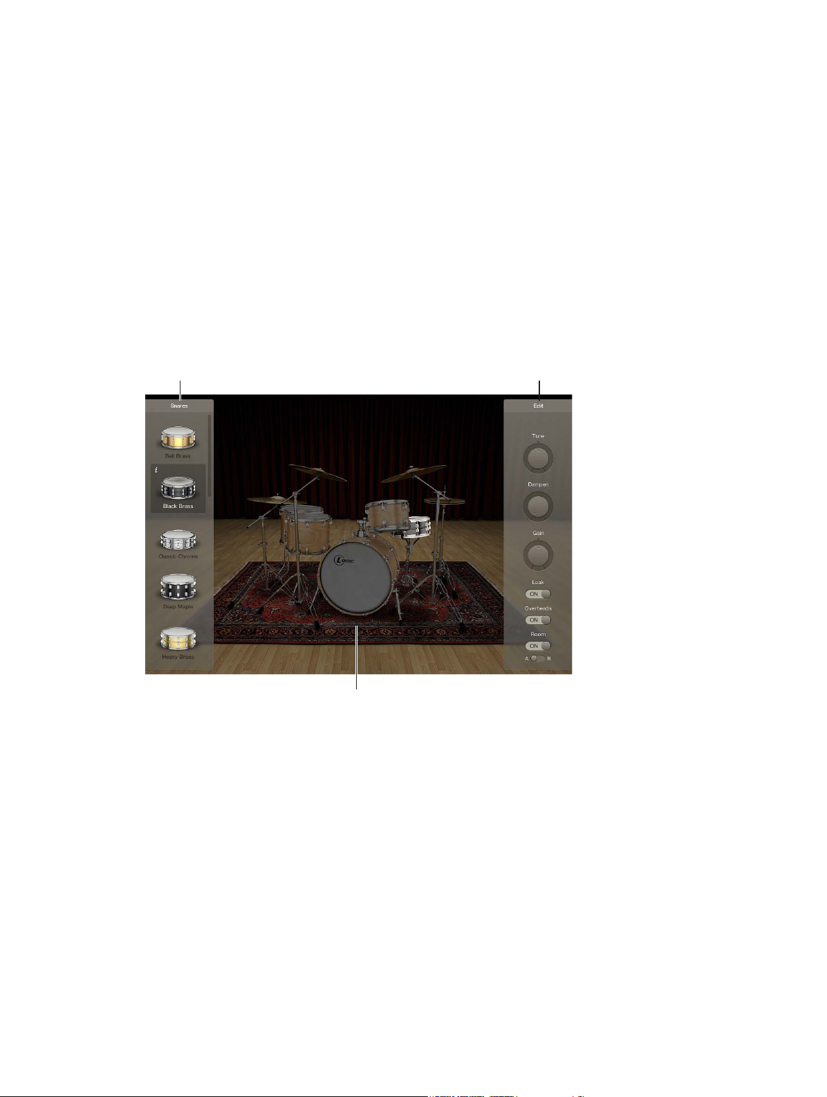
Edit panelExchange panel
Drum Kit Designer
1
Drum Kit Designer overview
Drum Kit Designer lets you build custom drum kits from a wide selection of drum and percussion
sounds. It also provides controls that change sound characteristics and the level of each piece in
your kit.
Further settings allow you to use dierent microphones and rooms to enhance Producer kits.
Producer kits are identied in the Library by a “+” at the end of the patch name. See “Add
drummers to a project” in Logic Pro Help for information on Producer kits.
Drum kit
Drum Kit Designer’s interface is divided into the following main areas.
•
Drum kit: Click a drum kit piece to preview its sound and to open the Edit panel and the
Exchange panel if exchange pieces are available for that drum type.
•
Exchange panel: Shows all drums that are available for exchange (you may need to scroll).
•
Edit panel: Shows settings that change sound characteristics.
14
Page 15
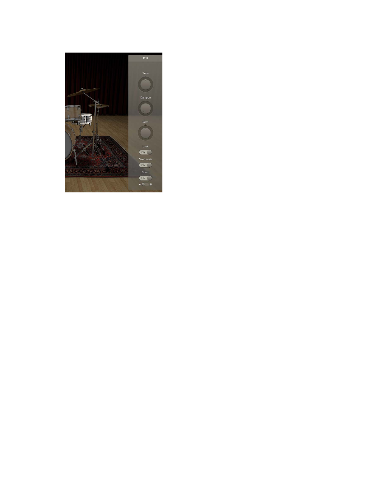
Drum Kit Designer Edit panel
The Edit panel is used to change sound characteristics and the level of each piece in your kit.
Edit panel parameters
•
Tune knob and eld: Rotate to adjust the pitch.
•
Dampen knob and eld: Rotate to adjust the sustain.
•
Gain knob and eld: Rotate to adjust the volume.
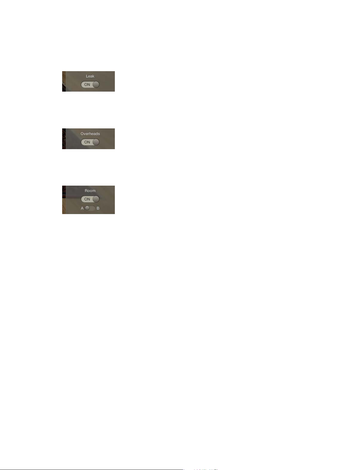
•
Leak switch (Producer kits only): Drag to On to include the sound in the mic of the other
kit pieces.
•
Overheads switch (Producer kits only): Drag to On to include the drum kit’s overhead mic in
the sound.
•
Room switch (Producer kits only): Drag to choose between rooms A and B or to turn o the
room emulation.
Chapter 1 Drum Kit Designer 15
Page 16
Use Drum Kit Designer
Drum Kit Designer shows a 3D representation of the drum kit for the currently loaded patch.
For all kits, you can preview the drums, edit the pitch, sustain, and volume of each drum kit piece,
and exchange the kick and snare drums. When working with Producer kits, you can additionally
exchange toms, cymbals, and hi-hat. Producer kits let you turn dierent microphones, such as
overheads or room mics, on or o.
Note: Producer kits and some drums are only available after you download additional content.
Drum Kit Designer also has additional parameters for adjusting the gain of other instrument
pieces, such as shaker, cowbell, and so on. See Drum Kit Designer extended parameters.
Preview a drum or percussion piece
m Click a drum or percussion piece.
The rst time you click any drum or percussion piece after opening the plug-in, one or two
panes open. You can exchange individual sounds in the Exchange panel to the left and can edit
individual drum or percussion piece settings in the Edit panel to the right.
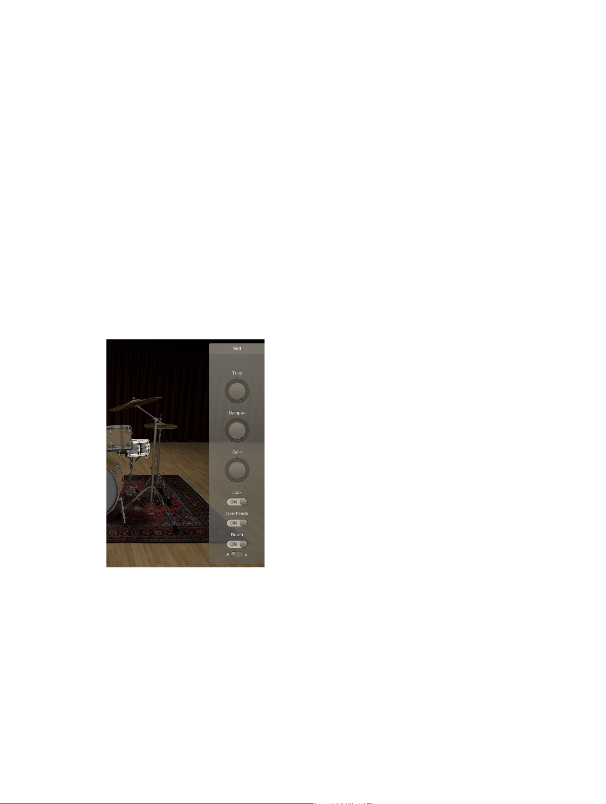
Adjust kit piece settings (all kits)
1 Click a drum or percussion piece.
The Edit panel opens to the right.
•
Toms: Click the tab for the tom you want to edit, or click the All tab to adjust the tone of
all toms.
•
Cymbals: Click the tab for the crash cymbal you want to edit, or click the All tab to adjust the
tone of both crash cymbals. The ride cymbal can be edited directly.
•
Kicks and snares: There are no tabs, so make your adjustments with the controls.
Chapter 1 Drum Kit Designer 16
Page 17
2 To adjust settings, do any of the following:
•
To adjust the pitch: Drag the Tune control vertically, or double-click the eld and enter a
new value.
•
To adjust the sustain: Drag the Dampen control vertically, or double-click the eld and enter a
new value.
•
To adjust the volume: Drag the Gain control vertically, or double-click the eld and enter a
new value.
3 To close open panels, click anywhere in the plug-in window background.
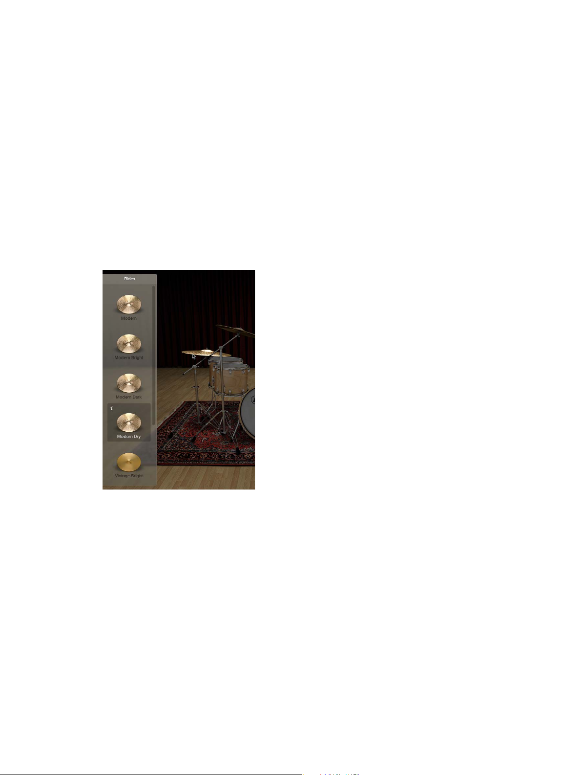
Exchange a kit piece
For all kits, you can exchange kick and snare. When working with Producer kits, you can
additionally exchange toms, cymbals, and hi-hat.
Note: Producer kits and some drums are only available after you download additional content.
1 Click a drum or percussion piece.
The Exchange panel opens to the left if exchange pieces are available for that kit piece.
2 Click the Info button of a selected piece to view its description.
3 Click the kit piece that you want to exchange in the Exchange panel. You may need to scroll in
order to nd the piece you want to use.
The piece is exchanged and the respective drum sound is loaded.
Note: The toms and the crash cymbals can only be exchanged as a group.
Chapter 1 Drum Kit Designer 17
Page 18
4 To close the panels, click anywhere in the plug-in window background.
Adjust mic settings (Producer kits only)
In the Edit panel, do any of the following:
m To include the sound in the mic of the other kit pieces: Turn on the Leak switch.
This turns microphone bleed on or o, where the sound of a kit piece is picked up by the
dierent mics from other kit pieces.
m To include the kit piece’s overhead mic in the sound: Turn on the Overheads switch.
This turns the overhead mic for the selected kit piece on or o.
m To choose a room emulation to use with the sound: Choose between rooms A and B. You can also
turn o the room microphones.
Rooms A and B determine which room mic setup is used with the kit piece.
Chapter 1 Drum Kit Designer 18
Page 19

Drum Kit Designer extended parameters
Drum Kit Designer provides additional parameters that are accessed by clicking the disclosure
triangle at the lower left.
The Input Mapping pop-up menu lets you choose dierent mappings that provide enhanced
control of HiHats. The maps also change the way Drum Kit Designer sounds are assigned across
the MIDI note range. See Drum Kit Designer mappings.
Extended parameters
•
Input Mapping pop-up menu: Choose a keyboard mapping mode.
•
GM: Drums are mapped to the GM standard.
•
GM + ModWheel controls HiHat opening level: The keyboard Mod Wheel is mapped for
hi-hat control. Additional sounds are also mapped to keyboard zones above and below the
standard GM note mapping range.
•
V-Drum: Drums are mapped to work with V-Drum hi-hat, cymbal, and drum triggers.
•
Gain sliders: Drag the slider (or drag vertically in the eld) to adjust the level of the
corresponding sound (if available in the kit).
•
Shaker Gain
•
Tambourine Gain
•
Claps Gain
•
Cowbell Gain
•
Sticks Gain
Chapter 1 Drum Kit Designer 19
Page 20
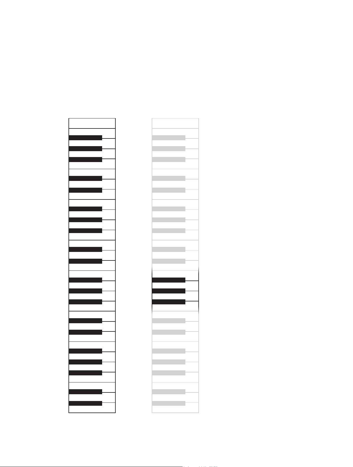
Drum Kit Designer mappings
C1
C0
GM Standard GM + ModWheel
Drum Kit Designer is compatible with the GM standard. You can also choose GM+, which maps
the keyboard ModWheel for hi-hat control. This means that you can use the keyboard ModWheel
to adjust the degree to which the hi-hat opens and closes during the drum performance.
Drum Kit Designer is also compatible with the V-Drum standard.
The image shows how drum sounds are remapped when dierent modes are chosen with the
Input Mapping pop-up menu in the extended parameters.
Note: A number of alias drums sounds are included for GM compatibility purposes.
Shaker
C3
Ride In
Cowbell
Tambourine
Ride Out
Crash Left
C2
Hi-Hat Open Edge
Hi-Hat Foot
Hi-Hat Closed Tip
Claps
Snare Sidestick
Snare Edge
Rimshot Edge
Crash Right
Ride Bell
Ride Edge
High Tom
High Tom
High Mid Tom
Low Mid Tom
Low Tom
Low Tom
Snare Rimshot
Snare Center
Kick
Kick
Hi-Hat Foot Close
Hi-Hat Foot Splash
Shaker
C3
Cowbell
Tambourine
Ride Out
Crash Left
C2
Hi-Hat Edge
Hi-Hat Shank
Hi-Hat Tip
Claps
Snare Sidestick
C1
Snare Edge
Rimshot Edge
Ride In
Crash Right
Ride Bell
Ride Edge
High Tom
High Tom
High Mid Tom
Low Mid Tom
Low Tom
Low Tom
Snare Rimshot
Snare Center
Kick
Kick
Hi-Hat Foot Close
Hi-Hat Foot Splash
Crash Right Stop
Crash Left Stop
C0
Crash Right Stop
Crash Left Stop
Chapter 1 Drum Kit Designer 20
Page 21
Amplifier parameters
Filter parameters
Oscillator parameters
ES1
2
ES1 overview
ES1 emulates the circuits of analog synthesizers in a simple, streamlined interface.
ES1 produces sounds using subtractive synthesis. It provides an oscillator and sub-oscillator
that generate harmonically rich waveforms. You subtract (cut, or lter out) portions of these
waveforms and reshape them to create new sounds. The ES1’s tone-generation system also
provides exible modulation options that make it easy to create punchy basses, atmospheric
pads, biting leads, and sharp percussion.
If you’re new to synthesizers, see Synthesizer basics overview on page 472, which will introduce
you to the terminology and give you an overview of dierent synthesis systems and how
they work.
Modulation parameters
Envelope parameters
Global parameters
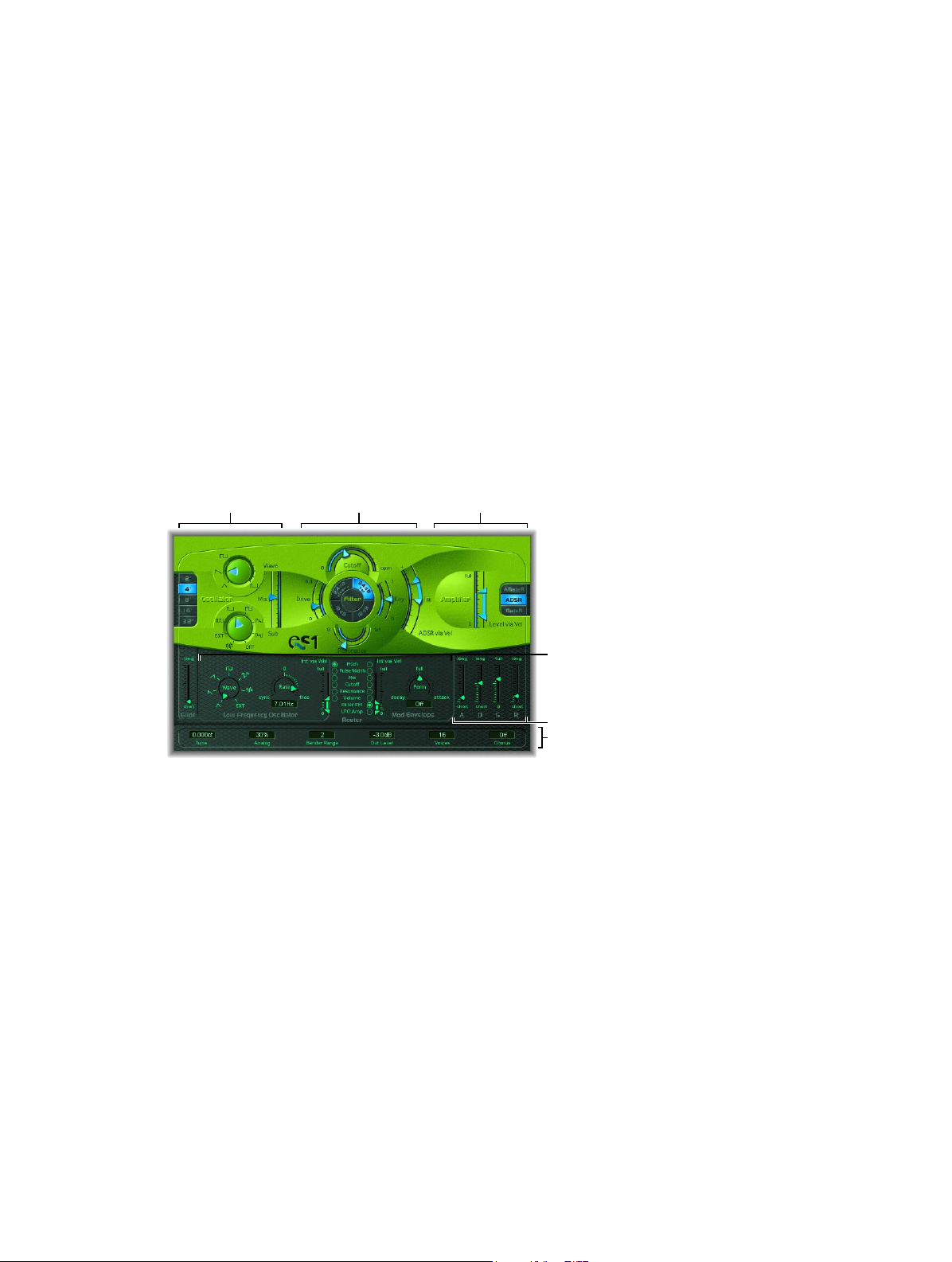
ES1 is divided into six main areas.
•
Oscillator parameters: Located in the upper left, the oscillators generate the basic waveforms
that form the basis of your sound. See ES1 oscillator parameters overview on page 22.
•
Global parameters: Located in the bottom green/gray strip, global sound control parameters
are used to assign and adjust global tuning, activate the in-built chorus, and so on. You can
use the chorus to color or thicken the sound. See ES1 global parameters on page 24.
•
Filter parameters: Located in the upper-middle section with the circular Filter area as well as the
Drive and Key scaling parameters, the lter is used to contour the waveforms sent from the
oscillators. See ES1 lter parameters overview on page 25.
•
Amplier parameters: Located in the upper right, the amplier parameters allow you to ne-
tune the behavior of your sound’s level. See ES1 amplier parameters on page 27.
•
Envelope parameters: Located to the right in the dark green/gray area, the ADSR sliders
are used to control both lter cuto and the amplier level over time. See ES1 envelope
parameters overview on page 28.
21
Page 22
•
Modulation parameters: Located to the left and middle in the dark green/gray area, the
modulation sources, modulation router, modulation envelope, and amplitude envelope
are used to modulate the sound in a number of ways. See ES1 modulation parameters
overview on page 30.
ES1 oscillator parameters
ES1 oscillator parameters overview
ES1 includes a primary oscillator and a sub-oscillator. The primary oscillator generates a
waveform that is sent to other parts of the synthesizer for processing or manipulation.
The sub-oscillator generates a secondary waveform one or two octaves below that of the
primary oscillator.
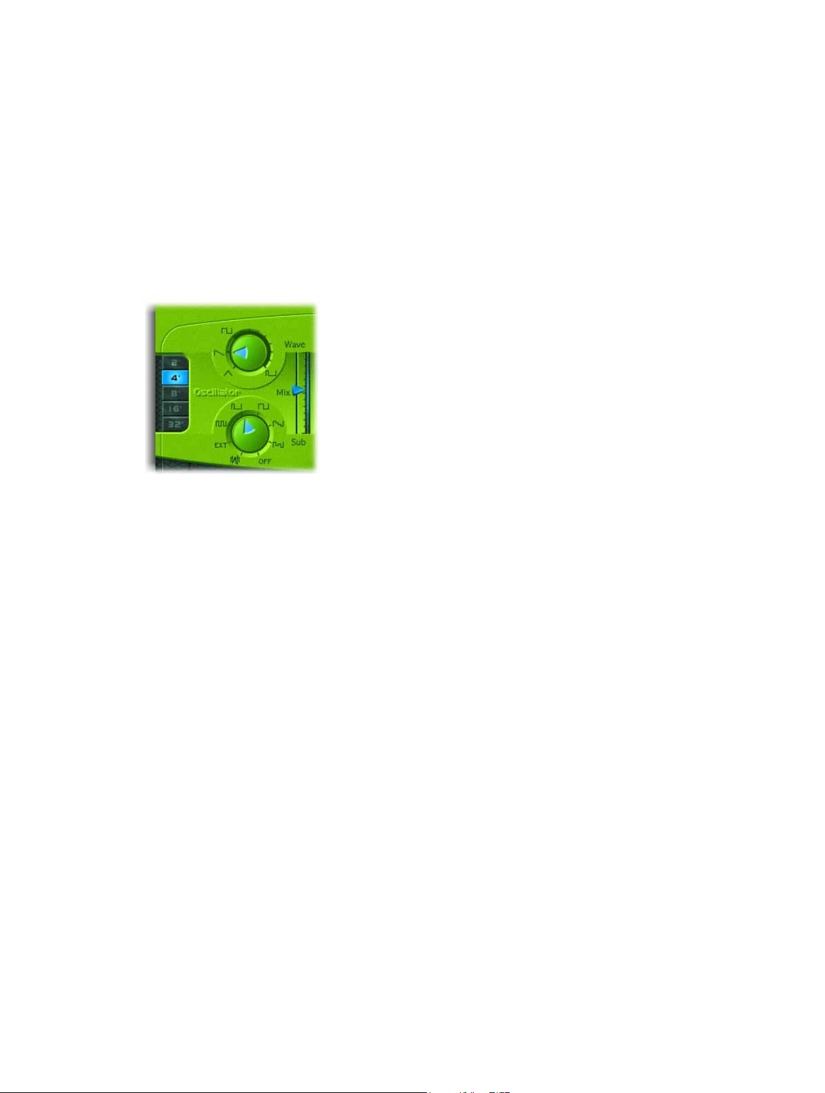
Oscillator parameters
•
Wave knob: Rotate to select the waveform of the primary oscillator, which is responsible for the
basic color of the tone. See ES1 oscillator waveforms on page 23.
•
Mix slider: Drag to set the level relationship between the primary and sub-oscillator signals.
(When the sub-oscillator is switched o, its output is completely removed from the signal
path.)
•
Sub knob: Rotate to generate square, pulse, and white-noise waveforms with the sub-oscillator.
The sub-oscillator also allows you to route a side-chain signal through the ES1 synthesizer
engine. See Use the ES1 sub-oscillator on page 23.
•
2’, 4’, 8’, 16’, and 32’ buttons: Click to transpose the pitch of the oscillators up or down by octaves.
The lowest setting is 32 feet and the highest is 2 feet. The use of the term feet to determine
octaves comes from the measurements of organ pipe lengths. The longer and wider the pipe,
the deeper the tone.
Modulate ES1 pulse width
m Rotate the Wave knob to a position between the square wave and pulse wave symbols.
The pulse width can also be automatically modulated in the modulation section (see Use the ES1
router on page 30). Modulating the pulse width with a slowly cycling LFO, for example, allows
periodically mutating, fat bass sounds.
Chapter 2 ES1 22
Page 23

ES1 oscillator waveforms
The table outlines the basic tones of the oscillator waveforms—how they aect your
synthesizer sound.
Waveform Basic tone Comments
Sawtooth Warm and even Useful for strings, pads, bass, and
brass sounds
Triangle Sweet sounding, softer than
sawtooth
Square Hollow and “woody” sounding Useful for basses, clarinets, and
Pulse “Nasal” sounding Great for reed instruments, synth
Useful for utes, pads
oboes
blips, basses
Use the ES1 sub-oscillator
The ES1 sub-oscillator is used to make your sound richer. Its pitch matches the frequency of the
main oscillator. You can choose from the following sub-oscillator waveform options:
•
A square wave that plays one or two octaves below the frequency of the primary oscillator
•
A pulse wave that plays two octaves below the frequency of the primary oscillator
•
Variations of these waveforms, with dierent mixes and phase relationships, resulting in
various sounds
•
White noise, which is useful for creating percussion sounds as well as wind, surf, and rain
sounds
•
OFF, which allows you to disable the sub-oscillator
•
EXT, which allows you to run an external channel strip signal through the ES1 synthesizer
engine, by using a side chain
Process a channel strip signal through the ES1 synthesizer engine
1 Set the Sub knob to EXT.
2 Choose the side-chain source channel strip from the Side Chain pop-up menu in the upper-right
corner of ES1.
Chapter 2 ES1 23
Page 24

ES1 global parameters
The global parameters aect the overall sound, or behavior, of the ES1 and are found primarily in
the strip that spans the lower edge of the ES1 interface. The Glide slider is displayed above the
left end of the strip.
Global parameters
•
Glide slider: Drag to set the amount of time it takes to slide between the pitches of each
triggered note. The Glide trigger behavior depends on the value set in the Voices eld (see
below).
•
Tune eld: Drag to tune the instrument in cents. One cent is 1/100th of a semitone.
•
Analog eld: Drag to slightly, and randomly, change the pitch of each note and the cuto
frequency. This emulates the oscillator detuning and lter uctuations of polyphonic analog
synthesizers, due to heat and age.
If you set the Analog parameter to 0%, the oscillator cycle start points of all triggered voices
are synchronized. This can be useful for percussive sounds, when you want to achieve a
sharper attack characteristic.
If you set the Analog parameter higher than 0%, the oscillators of all triggered voices can
cycle freely. Use higher values if you want a warm, analog type of sound—where subtle sonic
variations occur for each triggered voice.
•
Bender Range eld: Drag to set the sensitivity of the pitch bender, in semitone steps.
•
Neg Bender Range slider (Extended Parameters area): Drag to set the negative (downward)
pitch bend range in semitone steps. The default value is Pos PB (positive pitch bend), which
essentially means that there is no downward pitch bend available. (Click the disclosure triangle
at the lower left of the ES1 interface to access the Extended Parameters area.)
•
Out Level eld: Drag to set the ES1 master volume.
•
Voices eld: Drag to set the maximum number of notes that can be played simultaneously—up
to 16 voices.
When Voices is set to Legato, the ES1 behaves like a monophonic synthesizer—with single
trigger and ngered portamento engaged. This means that if you play legato, a portamento—
glide from one note to the next—will happen. If you release each key before pressing a
new one, the envelope is not triggered by the new note, and there is no portamento. Use
this feature to create pitch bend eects, without touching your keyboard’s pitch bender, by
choosing a high Glide parameter value when using the Legato setting.
•
Chorus eld: Click to choose a classic stereo chorus eect, an ensemble eect, or to disable the
eects processor.
•
O disables the built-in chorus circuit.
•
C1 is a typical chorus eect.
•
C2 is a variation of C1 and is characterized by a stronger modulation.
•
Ens(emble) uses a more complex modulation routing, creating a fuller and richer sound.
Chapter 2 ES1 24
Page 25

ES1 lter parameters
ES1 lter parameters overview
This section outlines the lter parameters of the ES1.
Filter parameters
•
Cuto slider: Drag to set the cuto frequency of the ES1’s lowpass lter.
•
Resonance slider: Drag to cut or boost the portions of the signal that surround the frequency
dened by the Cuto parameter. Boost can be set so intensively that the lter begins to
oscillate by itself (see Drive the ES1 lter to self-oscillate on page 26).
Tip: You can simultaneously adjust the cuto frequency and resonance parameters by
dragging vertically (cuto) or horizontally (resonance) on the word Filter, found in the center
of the black circle.
•
Slope buttons: The lowpass lter oers four dierent slopes of band rejection above the cuto
frequency. Click one of the buttons to choose a slope (amount of rejection, expressed in
decibels (dB) per octave):
•
24 dB classic: Mimics the behavior of a Moog lter. Turning up the resonance results in a
reduction of the low end of the signal.
•
24 dB fat: Compensates for the reduction of low frequency content caused by high
Resonance values. This resembles the behavior of an Oberheim lter.
•
12 dB: Provides a soft, smooth sound that is reminiscent of the early Oberheim
SEM synthesizer.
•
18 dB: Resembles the lter sound of Roland’s TB-303.
•
Drive slider: Drag to change the behavior of the Resonance parameter, which eventually
distorts the sound of the waveform. Drive is actually an input level control, which allows you
to overdrive the lter.
•
Key slider: Drag to set the eect that keyboard pitch (the note number) has on lter cuto
frequency modulation.
•
If Key is set to zero, the cuto frequency does not change, no matter which key you strike.
This makes the lower notes sound comparatively brighter than higher notes.
•
If Key is set to maximum, the lter follows the pitch, resulting in a constant relationship
between cuto frequency and pitch. This mirrors the properties of many acoustic
instruments, where higher notes sound both brighter in tone and higher in pitch.
Chapter 2 ES1 25
Page 26

•
ADSR via Vel sliders: Drag to determine how note velocity aects modulation of the lter cuto
frequency with the envelope generator. See ES1 envelope parameters overview on page 28.
•
Filter Boost button (Extended Parameters area): Turn on to increase the output of the lter by
approximately 10 decibels. The lter input has a corresponding decrease of approximately 10
decibels, maintaining the overall level. This parameter is particularly useful when applying high
Resonance values. See Drive the ES1 lter to self-oscillate. (Click the disclosure triangle at the
lower left of the ES1 interface to access the Extended Parameters area.)
Drive the ES1 lter to self-oscillate
If you increase the lter Resonance parameter to higher values, the lter begins to internally
feed back and, as a consequence, begins to self-oscillate. This results in a sine oscillation—a sine
wave—that is actually audible.
You can make the ES1 lter output a sine wave by following the steps below. This lets you play
the lter-generated sine wave with the keyboard.
Output a sine wave from the lter
1 Switch the Sub knob to O.
2 Drag the Mix slider to the very bottom (Sub).
3 Drag the Resonance slider to the maximum position (full).
4 If you want, click the disclosure triangle at the lower left to open the extended parameters, then
click the Filter Boost button.
Filter Boost increases the output of the lter by approximately 10 decibels, making the self-
oscillation signal much louder.
Chapter 2 ES1 26
Page 27

ES1 amplier parameters
The parameters in the ES1 Amplier section allow you to ne-tune the behavior of your sound’s
level. These are separate from the global Out Level parameter, which acts as the ES1’s master
volume control. See ES1 global parameters on page 24.
Amplier parameters
•
Level via Vel slider: Drag to determine how note velocity aects the synthesizer level. The
greater the distance between the arrows (indicated by the blue bar), the more the volume is
aected by incoming velocity messages.
•
Drag the upper arrow to set the level when you play hard (velocity=127).
•
Drag the lower arrow to set the level when you play softly (velocity=1).
•
To simultaneously adjust the modulation range and intensity, drag the blue bar—between
the arrows—and move both arrows at once.
•
Amplier envelope selector buttons: Click one of the buttons—AGateR, ADSR, or GateR—to
determine the ADSR envelope generator used for control of the amplier envelope. See ES1
envelope parameters overview on page 28.
Chapter 2 ES1 27
Page 28
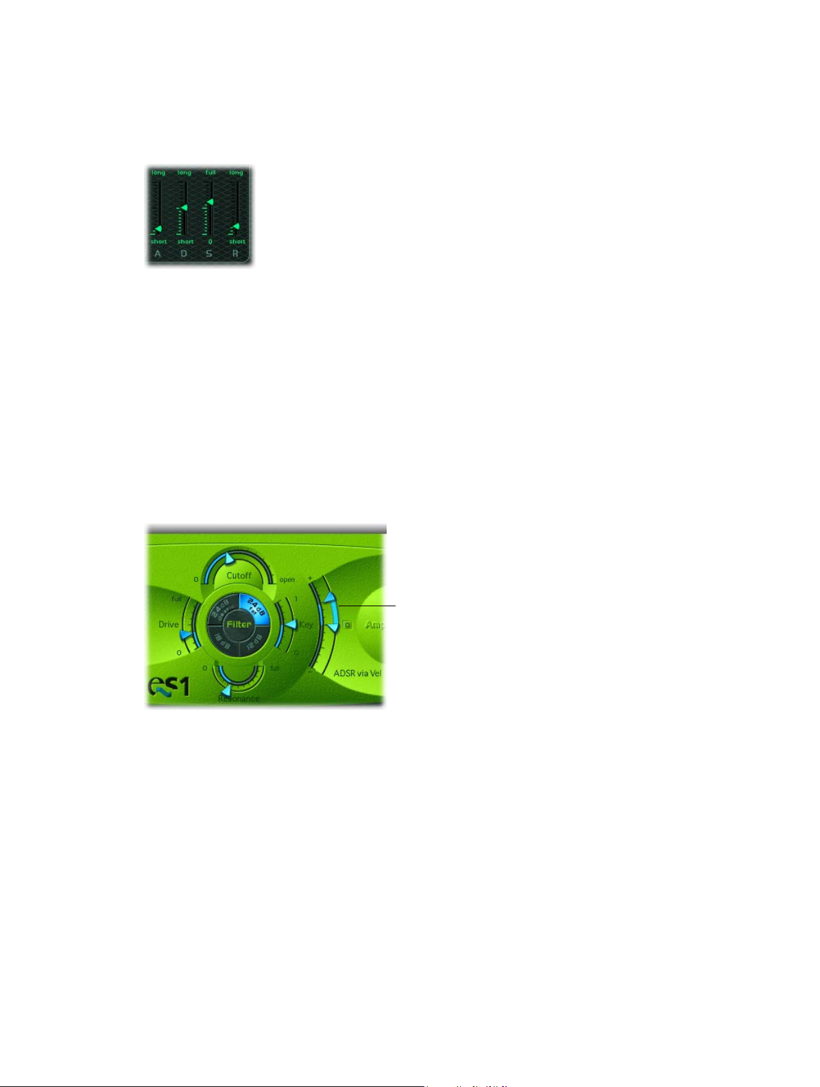
ES1 envelope parameters
ES1 envelope parameters overview
ES1 provides an attack, decay, sustain, and release (ADSR) envelope that can shape lter cuto
and the level of the sound over time.
Envelope Parameters
•
A(ttack) slider: Drag to set the time it takes for the envelope to reach the initial desired level.
•
D(ecay) slider: Drag to set the time it takes for the envelope to fall to the sustain level, following
the initial attack time.
•
S(ustain) slider: Drag to set the sustain level, which is held until the key is released.
•
R(elease) slider: Drag to set the time it takes the envelope to fall from the sustain level to a level
of 0.
ES1 lter cuto envelope modulation
The envelope generator modulates the lter cuto frequency over the course of a note’s
duration. The modulation intensity—and response to velocity information—is set by the arrows
on the ADSR via Vel slider in the Filter section.
ADSR via Vel slider
The modulation range is determined by the two arrows.
•
The lower arrow indicates the minimum amount of modulation.
•
The upper arrow indicates the maximum amount of modulation.
•
The blue bar between the arrows shows the dynamic range of this modulation. You can
simultaneously adjust the modulation range and intensity by dragging the blue bar.
Tip: If you’re unfamiliar with these parameters, set the Cuto parameter to a low value,
Resonance to a high value, and move both ADSR via Vel arrows upward. Constantly strike a note
on the keyboard while changing the arrows to learn how these parameters work.
Chapter 2 ES1 28
Page 29
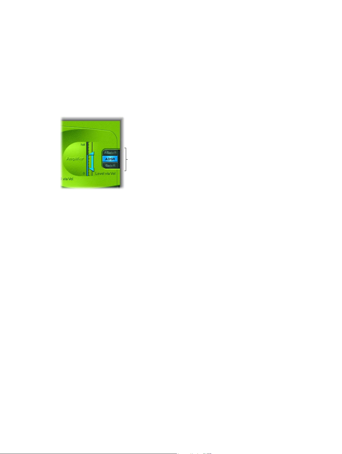
ES1 amplier envelope modulation
The AGateR, ADSR, and GateR buttons in the Amplier section determine which of the ADSR
envelope controls aect the amplier envelope. All ADSR parameters remain active for the lter.
The letters A, D, S, and R refer to the attack, decay, sustain, and release phases of the envelope
(see ES1 envelope parameters overview on page 28).
Gate refers to a control signal used in analog synthesizers that is sent to an envelope generator
when a key is pressed. As long as an analog synthesizer key is pressed, the gate signal maintains
a constant voltage. When Gate is used as a modulation source in the voltage-controlled amplier
(instead of the envelope), it creates an organ-type envelope without any attack, decay, or release
phase—in other words, an even, sustained sound.
Amplifier Envelope
Selector buttons
The ES1 amplier envelope selector buttons have the following eect on played notes:
•
AGateR: The Attack and Release sliders of the ADSR envelope control the attack and release
phases of the sound. In-between these phases, the Gate control signal is used to maintain a
constant level while a note is held. As soon as you release the key, the release phase begins.
The Decay and Sustain sliders of the ADSR Envelope have no impact on the sound’s level.
•
ADSR: The standard operating mode of most synthesizers, where the level of the sound over
time is controlled by the ADSR Envelope.
•
GateR: The Gate control signal is used to maintain a constant level while a note is held. As soon
as you release the key, the release phase begins. The Attack, Decay, and Sustain sliders of the
ADSR Envelope have no impact on the sound’s level.
Chapter 2 ES1 29
Page 30
ES1 modulation
ES1 modulation parameters overview
ES1 oers a number of simple yet exible modulation routing options. You use modulation to
add animation to your sound over time, making it more interesting, lively, or realistic. A good
example of this type of sonic animation is the vibrato used by orchestral string players.
Modulation EnvelopeRouterLFO parameters
Modulation parameters
•
LFO parameters: Used to modulate other ES1 parameters. See Use the ES1 LFO on page 31.
•
Router: Enables you to choose the ES1 parameters that are modulated. See Use the ES1
router on page 30.
•
Modulation Envelope: A dedicated modulation control source that can be used to control
various ES1 parameters, or it can be used to control the LFO level. See Use the ES1 modulation
envelope on page 32.
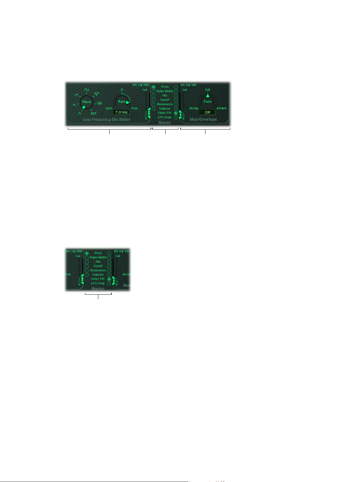
Use the ES1 router
The router determines the ES1 parameters (targets) that are modulated by the LFO and by the
modulation envelope. The buttons in the left column set the target for LFO modulation. The
buttons in the right column set the target for the modulation envelope.
Parameter target
buttons
Router parameters
•
Pitch buttons: Click to modulate the pitch—the frequency—of the oscillators.
•
Pulse Width buttons: Click to modulate the pulse width of the pulse wave.
•
Mix buttons: Click to modulate the mix between the primary oscillator and the sub-oscillator.
•
Cuto buttons: Click to modulate the cuto frequency of the lter.
•
Resonance buttons: Click to modulate the resonance of the lter.
•
Volume buttons: Click to modulate the main volume.
•
Filter FM button (modulation envelope only): Click to use the triangle wave of the oscillator
to modulate lter cuto frequency. This modulation can result in a pseudo-distortion of the
sound, or it can create metallic, FM-style sounds. The latter occurs when the only signal you
can hear is the self-oscillation of the resonating lter (see Drive the ES1 lter to self-oscillate on
page 26).
•
LFO Amp (modulation envelope only): Click to modulate the overall amount of LFO modulation.
Chapter 2 ES1 30
Page 31

Use the ES1 LFO
The LFO (low frequency oscillator) generates an adjustable, cyclic waveform that you can use to
modulate other ES1 parameters.
LFO parameters
•
Wave knob: Rotate to set the LFO waveform. Each waveform has its own shape, providing
dierent types of modulation.
•
You can choose the following waveforms: triangle; ascending and descending sawtooth;
square wave; sample & hold (random); and a lagged, smoothly changing random wave.
•
You can also choose EXT to assign a side-chain signal as a modulation source. Choose the
side-chain source channel strip from the Side Chain pop-up menu in the upper-right corner
of ES1.
•
Rate slider and eld: Drag to set the speed—the frequency—of the LFO waveform cycles.
•
If you set values to the right of 0, the LFO phase runs freely.
•
If you set values to the left of 0, the LFO phase is synchronized with the tempo of the host
application—with phase lengths adjustable between 1/96 bar and 32 bars.
•
When set to 0, the LFO outputs at a constant, full level, which allows you to manually control
the LFO speed with your keyboard’s modulation wheel. This can be useful, for example, if
you want to change the pulse width by moving your keyboard’s modulation wheel. You
would choose the pulse width as the LFO modulation target, using a button in the left
router column, and set the modulation intensity range using the Int via Whl slider.
•
Int via Whl slider: The upper arrow denes the intensity of LFO modulation if the modulation
wheel is set to maximum. The lower arrow denes the amount of LFO modulation if the
modulation wheel is set to 0. The distance between the arrows—shown as a green bar—
indicates the range of your keyboard’s modulation wheel.
You can simultaneously adjust the modulation range and intensity by dragging the green
bar, thus moving both arrows at once. Note that as you do so, the arrows retain their relative
distance from each other.
Chapter 2 ES1 31
Page 32

Use the ES1 modulation envelope
The modulation envelope can directly modulate the parameter chosen in the router. It
determines the time it takes for the modulation to fade in or fade out. At its center position (click
Full), modulation intensity is static—no fade-in or fade-out occurs. When set to its full value,
modulation intensity is at a constant level.
The modulation envelope allows you to set either a percussive type of decay envelope by
choosing low values or an attack type of envelope by choosing high values.
Modulation envelope parameters
•
Form slider and eld: Drag to set a fade-in (attack) or fade-out (decay) time for the modulation.
When set to the full position, the modulation envelope is turned o.
•
Int via Vel sliders: The top arrow sets the upper limit for the modulation envelope—for the
hardest keystrike (velocity = 127). The bottom arrow sets the lower limit—for the softest
keystrike (velocity = 1). The green bar between the arrows displays the impact of velocity
sensitivity on the intensity of the modulation envelope.
You can simultaneously adjust the modulation range and intensity by dragging the green
bar, thus moving both arrows at once. Note that as you do so, the arrows retain their relative
distance from each other.
Modulate a parameter with velocity
1 Select a modulation target, such as Pulse Width, from the right column of the router.
2 Set the Form slider to full, and adjust the Int via Vel parameter as needed.
This results in a velocity-sensitive modulation of the oscillator pulse width.
More interestingly, you can directly control the LFO level if you click the LFO Amp(litude) button
in the right column of the router.
Fade the LFO modulation in or out
m To fade in the LFO modulation: drag the Form slider to a positive value—toward attack. The higher
the value, the longer it takes for you to hear the modulation.
m To fade out the LFO modulation: drag the Form slider to a negative value—toward decay. The
lower the value—closer to decay—the shorter the fade-out time is.
LFO control with envelopes is most often used for delayed vibrato, a technique many
instrumentalists and singers employ to intonate longer notes.
Set up a delayed vibrato
1 Drag the Form slider to the right—toward attack.
2 Select Pitch as the LFO target in the left column of the router.
3 Use the Wave knob to select the triangular wave as the LFO waveform.
4 Drag the Rate eld to an LFO rate of about 5 Hz.
5 Drag the upper Int via Wheel arrow to a low value, and the lower arrow to 0.
Chapter 2 ES1 32
Page 33

ES1 MIDI controllers
ES1 responds to the following MIDI continuous controller numbers (CC).
Controller number Parameter name
12 Oscillator pitch buttons
13 Oscillator waveform
14 Mix slider
15 Waveform of sub-oscillator
16 Drive slider
17 Cuto slider
18 Resonance slider
19 Slope buttons
20 ADSR via Vel (lower slider)
21 ADSR via Vel (upper slider)
22 Attack slider
23 Decay slider
24 Sustain slider
25 Release slider
26 Key slider
27 Amplier Envelope Selector buttons
28 Level via Velocity (lower slider)
29 Level via Velocity (upper slider)
30 Chorus parameter
31 Modulation envelope target
102 Modulation envelope form slider
103 Modulation envelope: Int via Vel parameter
(lower slider)
104 Modulation envelope: Int via Vel parameter
(upper slider)
105 LFO rate
106 LFO waveform
107 LFO modulation target
108 LFO: Int via Whl (lower slider)
109 LFO: Int via Whl (upper slider)
110 Glide slider
111 Tune parameter
112 Analog parameter
113 Bender Range parameter
114 Out Level parameter
115 Voices parameter
Chapter 2 ES1 33
Page 34

ES2
3
ES2 overview
ES2 combines subtractive synthesis with elements of FM and wavetable synthesis to help
you generate an extraordinary variety of sounds. This makes it the perfect choice for creating
powerful pads, evolving textures, rich basses, or synthetic brass.
If you’re new to synthesizers, see Synthesizer basics overview on page 472, which introduces you
to the fundamentals and terminology of dierent synthesis systems.
The three oscillators of the ES2 provide classic analog synthesizer waveforms (including noise)
and 100 single-cycle waveforms, known as Digiwaves. This raw material forms the basis for
sounds that range from fat analog to harsh digital sounds, or hybrids of the two. You can also
cross-modulate oscillators, making it easy to create FM-style sounds. Further options include the
ability to synchronize and ring-modulate the oscillators or to mix a sine wave directly into the
output stage, to thicken the sound.
ES2 features a exible modulation router that oers up to ten simultaneous (user-dened)
modulation routings. Further modulation options include the unique Planar Pad—which
provides control of two parameters on a two-dimensional grid. The Planar Pad itself can be
controlled by the sophisticated Vector Envelope. This is a multipoint, loop-capable envelope that
makes it easy to create complex, evolving sounds.
Lastly, Distortion, Chorus, Phaser, and Flanger eects are built into the ES2.
If you want to begin experimenting right away, there are a number of settings to try. There
are also two tutorials that provide tips and information, and invite you to explore the ES2. See
ES2 sound design from scratch overview on page 95 and ES2 sound design with templates on
page 106.
Note: You will nd tasks that cover the use of parameters as modulation targets or sources
throughout these pages. This underlines one of ES2’s greatest strengths—namely, the vast
modulation possibilities it oers. Follow the steps in these tasks to create expressive, evolving
sounds. See ES2 modulation overview on page 59.
34
Page 35

ES2 interface
Modulation router
ES2’s graphical interface is divided into the following main areas.
Global
parameters
Modulation controls and
parameters
•
Oscillator section: The oscillator parameters are shown in the upper-left area of the
Oscillator section
Global parameters
Effect section
Filter section
Planar Pad
Amplifier
parameters
Click here to
display the Vector
Envelope.
Random
parameters
Macro Sound
parameters
ES2 interface. The Triangle is used to set the mix relationships between the three oscillators.
See ES2 oscillator parameters overview on page 37.
•
Global parameters: A number of related global parameters that directly inuence the overall
output of the ES2, such as Tune, are found to the left of the oscillators, and above the amplier
and lter parameters. See Global parameters overview on page 47.
•
Filter section: The circular area houses the lter section, including the Drive and Filter
FM parameters. See ES2 lter overview on page 50.
•
Amplier parameters: The area at the top right contains the output parameters, where you
can set the overall volume of the ES2, and add a sine signal at the output stage. See Use ES2’s
dynamic stage on page 58.
•
Modulation router or Vector Envelope: The dark strip across the center of the ES2 interface is
shared by the modulation router and the Vector Envelope. Use the buttons at the right end of
this section to switch between the two.
•
The router links modulation sources, such as the envelopes and other parameters shown in
the lower portion of the interface, to modulation targets, such as the oscillators and lters.
See Use the modulation router on page 60.
•
The Vector Envelope is a exible, powerful envelope generator that provides extensive
control over your sound. See Use the Vector Envelope on page 70.
Chapter 3 ES2 35
Page 36

•
Modulation controls and parameters: The area immediately below the router is where you can
assign and adjust the modulation generator parameters (such as LFO and envelope controls).
See ES2 modulation overview on page 59.
•
Planar Pad: The square area at the top right is a two-dimensional controller known as the
Planar Pad. The Planar Pad facilitates the simultaneous manipulation of two assignable
parameters, and can be controlled with the mouse, another controller, or the Vector Envelope.
See Use the Planar Pad on page 77.
•
Eect section: The built-in eect-processing options are found to the right of the output
parameters. See ES2 integrated eects processor on page 88.
•
Macro and MIDI controller parameters: The area shown on the thin, gray strip at the bottom can
display either Macro parameters or MIDI controller assignments. The preassigned macro sound
parameters are perfect for quick tweaks to the ES2’s sound (and that of ES2-based GarageBand
instruments). You can reassign MIDI control numbers for these parameters. See ES2 macro and
controller assignment overview on page 90.
Chapter 3 ES2 36
Page 37

ES2 sound sources
(Coarse) Frequency knob
ES2 oscillator parameters overview
ES2 oscillators are used to generate one or more waveforms. This signal is then sent to other
portions of the synthesizer engine for shaping, processing, or manipulation.
•
Oscillators 2 and 3 are almost identical to each other, but they dier from oscillator 1.
•
Oscillator 1 can be frequency modulated by oscillator 2, for FM synthesis sounds.
•
Oscillators 2 and 3 can be synchronized to, or ring modulated with, oscillator 1. They also have
rectangular waves with either user-dened xed pulse widths or pulse width modulation
(PWM) features.
•
You can use the modulation router to simultaneously change the pulse widths of rectangular
waves generated by oscillator 1 and the synchronized and ring-modulated rectangular waves
of oscillators 2 and 3.
Oscillator on/off button
Oscillator Mix (Triangle)
Oscillator parameters
•
Oscillator on/o buttons: The number to the right of each oscillator activates or deactivates
each oscillator independently. A green numeric button indicates an active oscillator. A gray
numeric button denotes an inactive oscillator. Deactivating an oscillator saves computer
processing power.
•
Wave knobs: Rotate to choose the waveform that an oscillator generates. The waveform is
responsible for the basic tonal color. See ES2 basic oscillator waveforms on page 38.
•
(Coarse) Frequency knobs: Rotate to set the oscillator’s pitch, in semitone steps, over a range
of ±3 octaves. Because an octave consists of 12 semitones, the ±12, 24, and 36 settings
represent octaves.
•
(Fine) Frequency value elds: Fine-tune the oscillator frequency (pitch). The left numbers show
the semitone s setting, and the right numbers show the cent c setting (1 cent = 1/100th
semitone). For example, an oscillator with the value 12 s 30 c sounds an octave (12 semitones)
and 30 cents higher than an oscillator with the value 0 s 0 c. Drag vertically to adjust
each value.
•
Oscillator Mix (Triangle): Move the pointer in the Triangle to cross-fade (set the level
relationships) between the three oscillators. See Balance ES2 oscillator levels on page 45.
Wave knob
(Fine) Frequency
value field
Chapter 3 ES2 37
Page 38

ES2 basic oscillator waveforms
All ES2 oscillators output a number of standard waveforms—sine, pulse, rectangular, sawtooth,
and triangular waves—or, alternately, any of 100 Digiwaves (see Use ES2 Digiwaves on page 42).
The following table covers the basic waveforms:
Waveform Basic tone Comments
Pulse/Rectangular Nasal sounding Great for reed instruments, synth
blips, and basses
Square Hollow and woody sounding Useful for basses, clarinets,
and oboes. The pulse width
of (oscillator 2 and 3) square
waveforms can be smoothly scaled
between 50% and the thinnest of
pulses.
Sawtooth Warm and even Useful for strings, pads, bass, and
brass sounds
Triangle Sweet sounding, softer than
sawtooth
Sine A pure tone
Useful for utes and pad sounds
The sine wave of oscillator 1
can be frequency modulated
by oscillator 2. This kind of
modulation forms the basis of
FM synthesis (see Use frequency
modulation in ES2
on page 40).
Oscillators 2 and 3 also oer the selection of:
•
A rectangular wave, synchronized to oscillator 1
•
A sawtooth wave, synchronized to oscillator 1
•
A ring modulator, which is fed by the output of oscillator 1 and a square wave from oscillator 2
•
Colored noise for oscillator 3. See Use the ES2 noise generator on page 42.
Oscillator synchronization and ring modulation allow for the creation of very complex and
exible harmonic spectra. The principles behind oscillator synchronization are described in
Synchronize ES2 oscillators on page 46. Ring modulation principles are described in Use ring
modulation in ES2 on page 41.
Chapter 3 ES2 38
Page 39

Use pulse width modulation in ES2
You can alter the tonal color of rectangular waveforms by scaling the width of waveform pulses
to any value. This is known as pulse width modulation.
ES2 pulse width modulation features are extensive. For example, if rectangular waves are chosen
for all oscillators, you can simultaneously modulate the pulse width of oscillator 1 and the
synchronized pulse waves of oscillator 2 (or the square wave of oscillator 2’s ring modulator) and
oscillator 3.
Set a basic pulse width in oscillator 2 or 3
m Drag the waveform rotary control that surrounds the Wave knob (see the highlighted area in the
image above).
Only oscillators 2 and 3 allow you to dene a base (default) pulse width, prior to any pulse
width modulation.
Set up a pulse width modulation (of oscillator 1) in the router
1 Choose a rectangle wave for oscillator 1.
2 In the router, choose Osc1Wave as the target, and LFO1 as the source.
3 Adjust the modulation amount slider (try a value of 0.12).
4 Choose a sine wave for LFO 1.
5 Adjust the LFO 1 Rate (around 0.160 Hz for a slow sweep).
Chapter 3 ES2 39
Page 40

Use frequency modulation in ES2
The principle of frequency modulation (FM) synthesis was developed in the late 1960s and early
1970s by John Chowning. It was popularized by Yamaha’s range of DX synthesizers in the 1980s.
Although the ES2 can’t be compared with the DX series in the discipline of pure FM synthesis, it
can achieve some of the signature sounds of these instruments.
In pure FM synthesis, the frequency of one signal generator, or oscillator, is altered (modulated)
by another signal generator. Positive values from the second generator increase the frequency
of the rst generator. Negative values decrease the frequency. In a synthesizer, this type of
modulation takes place in the audible range. Depending on the design of the instrument, you
can hear the signals of either the rst oscillator alone (being modulated by the other oscillator),
or both oscillators. The interaction between the two generators alters the waveform signal of the
rst oscillator and introduces a number of new harmonics. This harmonic spectrum can then be
used as the source signal for further sound processing, such as ltering, envelope control, and so
on. See Frequency modulation (FM) synthesis on page 493 for further information.
In ES2, the frequency of oscillator 1 (with a sine wave chosen—11 o’clock position for the Wave
knob) can be modulated by the output signal of oscillator 2.
•
When oscillator 2 outputs a positive signal, the frequency of oscillator 1 increases.
•
When oscillator 2 outputs a negative signal, the frequency of oscillator 1 decreases.
The net eect of speeding up or slowing down the frequency of oscillator 1 in each waveform
cycle is a distortion of the basic wave shape. This waveform distortion also has the side benet of
introducing a number of new, audible harmonics.
Important: The impact of any frequency modulations you perform depends on both the
frequency ratio and the modulation intensity of the two oscillators.
The “pure” FM synthesis method uses a sine wave for both the rst and second signal generator
(both oscillator 1 and 2 would be limited to generating a sine wave in ES2 if you stuck with this
approach). ES2, however, provides 100 Digiwaves and countless combinations of modulation
intensities and frequency ratios that can be used for either oscillator. This provides a vast pool of
harmonic spectra and tonal colors for you to experiment with.
Tip: The type of modulation that occurs can vary signicantly when dierent waveforms are
chosen for oscillator 2—the modulating oscillator—in particular.
Set the frequency ratio and adjust the modulation intensity
1 Adjust the Frequency (coarse and ne tune) parameter values of one, or both, oscillators.
2 Click (or drag) in the control range between the Sine and FM icons around the oscillator 1 Wave
knob.
This determines the amount, or intensity, of frequency modulation.
Chapter 3 ES2 40
Page 41

Use ring modulation in ES2
Ring modulation is a powerful tool for the creation of inharmonic, metallic, bell-like sounds. The
spectra resulting from its use are inharmonic at almost every frequency ratio. The ring modulator
is a device that dates back to the early days of the synthesizer.
A ring modulator has two inputs. At the output you hear both the sum and dierence
frequencies of the input signals. If you ring modulate a sine oscillation of 200 Hz with a sine
oscillation of 500 Hz, the output signal of the ring modulator consists of a 700 Hz (sum) and a
300 Hz (dierence) signal. Negative frequencies result in a change to the phase polarity of output
signals.
Tip: Use sawtooth and rectangular (pulse width modulated) input signals from oscillators 1 and
2, respectively, to create a much more complex output signal. The use of these harmonically rich
waveforms results in a number of extra sidebands becoming audible.
Create a ring-modulated sound
1 Set the oscillator 2 Wave knob to the Ring setting.
2 Experiment with dierent Frequency (main and ne tune) values for one, or both, oscillators.
The oscillator 2 ring modulator is fed with the output signal of oscillator 1 and a square wave,
generated by oscillator 2 itself. The pulse width of this square wave can be modulated (see Use
pulse width modulation in ES2 on page 39).
Chapter 3 ES2 41
Page 42

Use ES2 Digiwaves
In addition to the basic synthesizer waveforms, all ES2 oscillators provide 100 additional
waveforms, called Digiwaves. These are very short samples of the attack transients of various
sounds and instruments.
Choose a Digiwave
m Set the Wave knob to Sine (6 o’clock position), then do one of the following:
•
Control-click or right-click the Sine label, then choose a waveform from the pop-up menu.
•
Drag the Sine label vertically.
•
To select the Digiwave numerically, Shift-click the Sine label, then type a value.
Use the ES2 noise generator
The sonic palette of oscillator 3 is bolstered by the inclusion of a noise generator, which can be
activated by choosing the noise waveform. By default, oscillator 3’s noise generator generates
white noise.
White noise is dened as a signal that consists of all frequencies (an innite number) sounding
simultaneously, at the same intensity, in a given frequency band. The width of the frequency
band is measured in Hertz. Sonically, white noise falls between the sound of the consonant “F”
and breaking waves (surf). White noise is useful for synthesizing wind and seashore noises, or
electronic snare drum sounds.
You can also modulate the tonal color of the noise signal in real time—without using the main
lters of the ES2—by modulating the waveform of oscillator 3.
Change the noise color
1 Set up a modulation routing as follows: modulation target Osc3Wave, source ModWhl. The
modulation amount slider behaves somewhat dierently with this routing, essentially acting like
a lter.
2 Use negative modulation amount values (not −1.000) to set a descending lter slope that
roughly equates to 6 dB/octave. The sound becomes darker (red noise) as you adjust the mod
wheel downwards.
3 To tune this pseudo lter down to 18 Hz, set the modulation amount to −1.000. When Osc3Wave
is modulated positively, the noise becomes brighter (blue noise).
4 If you choose a modulation amount value of +1.000 for the Osc3Wave modulation target, the
lter cuto frequency is set to 18 kHz.
Chapter 3 ES2 42
Page 43

ES2 emulation of detuned analog oscillators
The Analog parameter randomly alters the pitch of each note and the lter cuto frequency.
•
Low Analog values can add a subtle richness to the sound.
•
Medium Analog values simulate the tuning instabilities of analog synthesizer circuitry, which
can be useful in achieving that much sought-after “warmth” of analog hardware synthesizers.
•
High Analog values result in signicant pitch instability, which can sound truly out of tune—
but this may be perfect for your needs.
Rotate the Analog knob to randomly alter the pitch of each note, and the lter cuto frequency.
Much like polyphonic analog synthesizers, all three oscillators maintain their specic frequency
deviation from each other, but the pitches of all three oscillators are randomly detuned by
the same Analog amount. For example, if the Analog detuning is set to around 20%, all three
oscillators (if used) randomly drifts by 20%.
Note: If ES2 is set to Mono or Legato keyboard mode, the Analog parameter is eective only
when Unison is turned on. In this situation, Analog sets the amount of detuning between the
stacked (unison) voices. If the Voices parameter is set to 1 and/or Unison is not active, the Analog
parameter has no eect. For more information about these parameters, see Set the ES2 keyboard
mode on page 48.
Chapter 3 ES2 43
Page 44

Stretch tuning in ES2
The (coarse) Frequency knob of each oscillator enables you to tune oscillators 1, 2, and 3 in
semitones or octaves. The (ne tune) Frequency parameter enables you to ne-tune each
oscillator in cents (1/100th of a semitone). Precise detuning between oscillators can result in
beats, or phasing, between the oscillator frequencies. The higher the played frequency/pitch,
the faster the phasing beats. High notes, therefore, may seem to be somewhat out of tune in
comparison with lower notes.
CBD (Constant Beat Detuning) can be used as a corrective tool to even out the beating between
oscillators, or it can be used as a creative tool to emulate stretch tuning. The latter can be
particularly important when you use an ES2 sound alongside an acoustic piano recording. This is
because acoustic pianos are intentionally tuned “out-of-tune” (from equal temperament). This is
known as stretch tuning, and results in the upper and lower keyboard ranges being slightly out of
tune with the center octaves but harmonically “in-tune” with each other.
Choose a CBD value to detune the harmonics of low note frequencies in a ratio proportionate
with the fundamental tone of the upper note frequencies.
CBD oers ve values: o, 25%, 50%, 75%, and 100%. If you choose 100%, the phasing beats are
almost constant across the entire keyboard range. This value may, however, be too high, because
the lower notes might be overly detuned at the point where the phasing of the higher notes
feels right. Try lower CBD values in cases where the bass notes are a little too far out of tune with
the upper keyboard range.
The reference pitch for CBD is C3 (middle C): its (de)tuning is constant, regardless of the chosen
CBD value.
Chapter 3 ES2 44
Page 45

Balance ES2 oscillator levels
The position of the pointer in the Triangle is described by two parameters—x and y
coordinates—which are used when automating the oscillator mix. These parameters, called
OscLevelX and OscLevelY, are available as targets in the router.
Drag the pointer in the Triangle to cross-fade—set the level relationships—between the three
oscillators. This is self-evident in use. If you move the pointer along one of the Triangle’s sides, it
cross-fades between the two closest oscillators, and the third oscillator is muted.
Click or drag in the
Triangle to change the
level balance between
the oscillators.
The position of the pointer (x and y coordinates) in the Triangle can also be controlled with
the Vector Envelope. Because the Vector Envelope features a loop function, it can be used as a
pseudo-LFO with a programmable waveform. For more information about this feature, see Use
the Vector Envelope on page 70.
Modulate triangle coordinates with the modulation wheel
1 Set up a modulation routing as follows: modulation target OscLevelX, source ModWhl. Adjust
the intensity.
2 Set up a second modulation routing as follows: modulation target OscLevelY, source ModWhl.
Adjust the intensity. You can choose other sources for these targets.
ES2 oscillator start points
The oscillators can run freely or can begin at the same phase position of their respective
waveform cycles each time a note is struck.
Choose free, soft, or hard from the Osc(illator) Start pop-up menu.
•
Free: The initial oscillator phase start point is random for each played note. This adds life to the
sound. The downside is that the output level may dier each time a note is played, making
the attack phase sound less punchy—even if the performance is identical each time—such
as when the note is triggered by a MIDI region. This setting is useful when you are emulating
sounds typical of hardware analog synthesizers.
•
Soft: The initial oscillator phase starts at a zero crossing for each played note. This mimics the
sonic character (and precision) typical of digital synthesizers.
•
Hard: The initial oscillator phase starts at the highest level in the waveform cycle for each
played note. The extra punch that this setting can provide is audible only if the ENV3 Attack
Time parameter is set to a low value—a very fast attack, in other words. This setting is highly
recommended for electronic percussion and hard basses.
Note: Osc Start soft and hard result in a constant output level of the initial oscillator phase every
time the sound is played back.
Chapter 3 ES2 45
Page 46

Synchronize ES2 oscillators
Typical oscillator sync sounds tend toward the aggressive, screaming leads that synthesizer
manufacturers like to talk about. The rectangular and sawtooth waveforms of oscillators 2
and 3 feature a Sync option. When this parameter is turned on, the phase of oscillator 2 or 3 is
synchronized with oscillator 1.
Every time oscillator 1 starts a new oscillation phase, the synchronized oscillator (oscillator 2
or 3) is also forced to restart its phase from the beginning. Between the waveform cycles of
oscillator 1, the waveform cycles of the synchronized oscillators run freely.
You can achieve interesting synchronized oscillator sounds by modulating the frequency of
the synchronized oscillator with an envelope generator. This constantly changes the number of
phases within a section of the synchronization cycle, resulting in corresponding changes to the
frequency spectrum.
Modulate the synchronized oscillator frequency with an envelope
1 Set the oscillator 2 Wave knob to Sync.
2 Set up a modulation routing as follows: modulation target Pitch2, source Env2.
3 Adjust the settings of Envelope 2.
Chapter 3 ES2 46
Page 47

ES2 global parameters
Global parameters
Global parameters
Global parameters overview
The ES2 global parameters aect the overall instrument sound produced by ES2. You can nd
global parameters to the left of the oscillators and above the lter and output sections.
Global parameters
•
Keyboard Mode buttons: Switch ES2 between polyphonic, monophonic, and legato behaviors.
See Set the ES2 keyboard mode on page 48.
•
Unison button: Click to turn unison mode on or o. See Use unison and voices in ES2 on
page 48.
•
Voices eld: Drag to set the maximum number of notes that can be played simultaneously.
•
Glide knob: Rotate to set the time it takes for the pitch of a played note to slide to the pitch of
the following played note. See Set the ES2 glide time on page 49.
•
Bend Range elds: Drag to dene the upward and downward pitch bend range. See Set the ES2
pitch bend range on page 49.
•
Tune eld: Drag to set the overall instrument pitch in cents. 100 cents equals a semitone step.
At a value of 0 c (zero cents), the central A key is tuned to 440 Hz, or concert pitch.
•
Analog knob: Rotate to randomly alter the pitch of each note and the lter cuto frequency.
See ES2 emulation of detuned analog oscillators on page 43).
•
Constant Beat Detuning (CBD) pop-up menu: Choose a CBD value to detune the harmonics of
low note frequencies in a ratio proportionate with the fundamental tone of the upper note
frequencies. See Stretch tuning in ES2 on page 44.
•
Osc(illator) Start pop-up menu: Choose free, soft, or hard from the Osc(illator) Start pop-up
menu. See ES2 oscillator start points on page 45.
Chapter 3 ES2 47
Page 48

Set the ES2 keyboard mode
A polyphonic instrument, such as an organ or a piano, allows several notes to be played
simultaneously. Many older analog synthesizers are monophonic, which means that only one
note can be played at a time, much like a brass or reed instrument. This shouldn’t be viewed as a
disadvantage; instead, it allows playing styles that are not possible with polyphonic instruments.
Change the keyboard mode
m Click the Poly, Mono, or Legato button.
•
In Mono mode, staccato playing retriggers the envelope generators every time a new note
is played. If you play in a legato style (play a new key while holding another), the envelope
generators are triggered only for the rst note you play legato, then they continue their curve
until you release the last legato played key.
•
Legato mode is also monophonic, but with one dierence: the envelope generators are
retriggered only if you play staccato—releasing each key before playing a new key. If you play
in a legato style, envelopes are not retriggered.
Note: On several monophonic synthesizers, the behavior in Legato mode is referred to as single
trigger, while Mono mode is referred to as multi trigger.
Use unison and voices in ES2
Unison mode in polyphonic analog synthesizers is typically monophonic, with all voices playing
simultaneously when a single note is struck. Because the voices of an analog synthesizer are
never perfectly in tune, the result is an extremely fat chorus eect with great sonic depth.
Use monophonic unison mode
1 Click the Mono or Legato button, depending on the keyboard mode you want to use. See Set the
ES2 keyboard mode.
2 Click the Unison button.
•
The intensity of the unison eect depends on the number chosen in the Voices parameter
eld. Increase the Voices value for a fatter sound. See Global parameters overview.
•
The intensity of detuning (voice deviation) is set with the Analog parameter. See ES2
emulation of detuned analog oscillators.
Use polyphonic unison mode
m Click the Poly and Unison buttons.
In poly/unison mode, each played note is eectively doubled—or, more correctly, the polyphony
value chosen with the Voices parameter is halved. These two voices are heard when you trigger
the note. Poly/unison has the same eect as setting the ES2 to mono/unison (Voices = 2), but
you can play polyphonically.
Chapter 3 ES2 48
Page 49

Set the ES2 glide time
The Glide parameter (also known as portamento) sets the time it takes for the pitch of one played
note to travel to the pitch of another played note.
Make portamento active
m Rotate the Glide knob.
Glide behavior is dependent on the chosen keyboard mode. See Set the ES2 keyboard mode.
•
If the keyboard mode is set to Poly or Mono, and Glide is set to a value other than 0,
portamento is active.
•
If Legato is chosen, and Glide is set to a value other than 0, you need to play legato (press a
new key while holding the old one) to activate portamento. If you don’t play in a legato style,
portamento won’t work. This behavior is also known as ngered portamento.
Set the ES2 pitch bend range
The Bend range elds determine the range for pitch bend modulation, typically performed with
your keyboard’s pitch bend wheel.
Set independent upward and downward bend ranges
m Drag in either eld to set a bend range.
Set an identical upward and downward bend range
1 Set the upward Bend range eld to Link mode.
This locks the upward and downward bend ranges, making them identical.
2 Set a downward Bend range value.
This is mirrored in the upward Bend range eld.
Note: A downward bend of 4 semitones results in a combined bend range of 8 semitones—9 if
you include the standard pitch, or “no bend” position.
Chapter 3 ES2 49
Page 50

Filter 1 Resonance
ES2 lter parameters
ES2 lter overview
ES2 features two discrete, and dierent, lters.
•
Filter 1 can operate as a lowpass, highpass, bandpass, band reject, or peak lter.
•
Filter 2 is a lowpass lter that oers variable slopes (measured in dB/octave).
Filter 1 Cutoff
Filter Blend
Filter 2 Cutoff
Filter 2 Resonance
Filter 2 Slope
Filter FM
Click here to choose a
parallel or series filter
Filter Drive
Filter 1 Mode
Filter button
Filter parameters
•
Filter button: Turns the entire lter section on or o. Deactivating the lter section makes it
easier to hear adjustments to other sound parameters, because the lters always heavily aect
the sound. Disabling the lters also reduces processor load.
•
Filter Conguration button: Switches between a parallel or series lter conguration. See ES2
lter conguration on page 51.
•
Filter Blend slider: Sets the balance between Filter 1 and Filter 2. See Cross-fade between ES2
lters on page 51.
•
Filter 1 Mode buttons: Switch Filter 1 between lowpass, highpass, bandpass, band reject, or peak
lter types. See ES2 Filter 1 modes on page 53.
•
Filter 2 Slope buttons: Switch Filter 2 between dierent slopes. See ES2 Filter 2 slopes on
page 53.
•
Cuto and Resonance: Rotate the Cuto and Resonance knobs to determine the cuto
frequency and resonance behavior of each lter. See Filter cuto and resonance overview on
page 54.
•
Filter Drive knob: Rotate to overdrive the lter, which aects each voice independently. See
Overdrive ES2 lters on page 56.
•
Filter FM knob: Rotate to set the amount of Filter 2 cuto frequency modulation with the
oscillator 1 frequency. See Modulate ES2’s Filter 2 Frequency on page 57.
configuration.
Chapter 3 ES2 50
Page 51

ES2 lter conguration
The Filter Conguration button lets you switch between a parallel and series lter routing. When
either is chosen, the entire circular lter element rotates, and the positions and direction of the
lter controls clearly indicate the signal ow. The button name also changes in each mode.
Series filter signal flow
Parallel filter signal flow
In the gure to the left, the lters are cabled in series. This means that the signal of all oscillators
(combined at the Oscillator Mix Triangle) passes through the rst lter, then this ltered signal
passes through Filter 2, if Filter Blend is set to 0, the middle position. The output signal of Filter 2
is then sent to the input of the dynamic stage (Amplier section).
In the gure to the right, the lters are cabled in parallel. If Filter Blend is set to 0, you’ll hear a
50/50 mix of the source signal, routed via Filter 1 and Filter 2. The output signals of the two lters
are then sent to the input of the dynamic stage. See Cross-fade between ES2 lters.
Cross-fade between ES2 lters
Filter Blend can have a signicant eect on the ES2 signal ow. Regardless of whether parallel
or series lter congurations are chosen, a Filter Blend setting of −1 results in only Filter 1 being
audible. A Filter Blend setting of +1 limits audibility to Filter 2. The gures illustrate the signal
ow between the Oscillator Mix stage (the Triangle) and the dynamic stage (the Amplier). The
signal ow through the lters and the lter overdrive circuit (the Drive parameter) are dependent
on the Filter Blend setting.
•
Filter Blend: Series lter conguration information
•
Use positive values for Filter Blend to partially bypass Filter 1.
•
Use negative values for Filter Blend to partially bypass Filter 2.
•
When zero or positive Filter Blend values are used, there is only one overdrive circuit for
both lters.
•
Use of negative Filter Blend values introduces another overdrive circuit, which distorts the
output signal of the oscillator mix stage before it is fed into the rst lter.
•
If Drive is set to 0, no distortion occurs.
+1:
+0,5:
–0,5:
–1:
Filter 1
Filter 1
Filter 1
0:
Drive
Drive
Drive
Drive
Drive
Filter 1
Filter 1
Filter 2
Filter 2
Filter 2
Drive
Drive
Filter 2
Filter 2
Chapter 3 ES2 51
Page 52

•
Filter Blend: Parallel lter conguration information
In a parallel conguration, the overdrive/distortion circuit—the Drive parameter—is always
wired after the oscillator mix stage—the Triangle—and before the lters. The lters receive
a mono input signal from the output of the overdrive circuit. The outputs of both lters are
mixed to mono via Filter Blend.
Filter 1
Mix
Drive
Filter 2
The Filter Blend parameter is available as a modulation target in the router. You can use manual
control sources, such as the modulation wheel, to change the lter blend; but the Filter Blend
target can also be used creatively, to rapidly switch or smoothly fade between the two lters.
You can also use velocity, or a combination of the Vector Envelope and Planar Pad as sources.
The latter allows for interesting lter control possibilities that evolve independently, or alongside
oscillator parameters that are also being controlled with the Vector Envelope.
Cross-fade between lters
m Drag the Filter Blend slider to cross-fade between the two lters when cabled in parallel.
•
If Filter Blend is set to the top position, you only hear the eect of Filter 1.
•
If Filter Blend is set to its lowest position, you only hear the eect of Filter 2.
•
In between these positions, the lters are cross-faded. You hear the eect of both lters.
You can also cross-fade the lters when they are cabled in series. In this situation, the
distortion—controlled by the Drive parameter—also needs to be considered, as this can be
positioned either before or in between the lters, depending on the Filter Blend setting you
choose.
Modulate Filter Blend with an LFO
1 Set up a modulation routing as follows: modulation target FltBlend, source LFO2.
2 Adjust the settings of LFO 2.
Chapter 3 ES2 52
Page 53

ES2 Filter 1 modes
Filter 1 can operate in several modes, allowing specic frequency bands to be ltered (cut away)
or emphasized.
Click one of the following lter mode buttons for Filter 1:
•
Lo (lowpass): Allows frequencies that fall below the cuto frequency to pass. The slope of
Filter 1 is xed at 12 dB/octave.
•
Hi (highpass): Allows frequencies above the cuto frequency to pass. The slope of Filter 1 is
xed at 12 dB/octave.
•
Peak: Filter 1 works as a peak lter. This allows the level in a frequency band to be increased.
The center of the frequency band is determined by the Cuto parameter. The width of the
band is controlled by the Resonance parameter.
•
BR (band reject): The frequency band directly surrounding the cuto frequency is rejected, but
frequencies outside this band can pass. The Resonance parameter controls the width of the
rejected frequency band.
•
BP (bandpass): The frequency band directly surrounding the cuto frequency is allowed
to pass. All other frequencies are cut. The Resonance parameter controls the width of the
frequency band. The bandpass lter is a two-pole lter with a slope of 6 dB/octave on each
side of the band’s center frequency.
ES2 Filter 2 slopes
Most lters do not completely suppress the portion of the signal that falls outside the frequency
range dened by the Cuto parameter. The slope, or curve, chosen for Filter 2 expresses the
amount of rejection below the cuto frequency in decibels per octave.
Slope buttons: Click any button to choose a Filter 2 slope: 12 dB, 18 dB, and 24 dB. The steeper the
slope, the more severe the eect on signal levels below the cuto frequency.
Fat button: Click the Fat button for 24 dB per octave of rejection. Fat mode has a built-in
compensation circuit that retains the sound’s bottom end. By comparison, the standard 24 dB
setting tends to make lower end sounds less rich.
Chapter 3 ES2 53
Page 54

ES2 lter cuto and resonance
Filter cuto and resonance overview
In every lowpass lter (ES2: Lo mode for Filter 1; Filter 2 is a lowpass lter), all frequency
portions above the cuto frequency are suppressed, or cut o, hence the name. If you’re new to
synthesizers and the concepts behind lters, see Synthesizer basics overview on page 472.
Cuto and resonance parameters
•
Cuto Frequency knob: Rotate to control the brilliance of the signal.
•
In a lowpass lter, the higher the cuto frequency is set, the higher the frequencies of signals
that are allowed to pass.
•
In a highpass lter, the cuto frequency determines the point where lower frequencies are
suppressed and only upper frequencies are allowed to pass.
•
In a bandpass/band rejection lter, the cuto frequency determines the center frequency for
the bandpass or band rejection lter.
•
Resonance knob: Rotate to emphasize or suppress portions of the signal above or below the
dened cuto frequency.
•
In a lowpass lter, Resonance emphasizes or suppresses signals below the cuto frequency.
•
In a highpass lter, Resonance emphasizes or suppresses signals above the cuto frequency.
•
In bandpass/band rejection lters, resonance emphasizes or suppresses the portions of
the signal—the frequency band—that surround the dened frequency, set with the Cuto
Frequency parameter.
Chapter 3 ES2 54
Page 55

Control two lter parameters simultaneously
Click here to
The ability to change the Cuto and Resonance controls at the same time is essential for creating
expressive synthesizer sounds.
m Drag one of the three chain symbols in the ES2 lter section.
simultaneously adjust
the cutoff and
resonance of Filter 1.
Click here to
simultaneously adjust
the cutoff of both Filter 1
and Filter 2.
Click here to
simultaneously adjust
the cutoff and
resonance of Filter 2.
•
The chain between Cut and Res of Filter 1 controls both the resonance (drag horizontally) and
cuto frequency (drag vertically) simultaneously.
•
The chain between Cut and Res of Filter 2 controls both the resonance (drag horizontally) and
cuto frequency (drag vertically) simultaneously.
•
The chain between Filter 1 Cut and Filter 2 Cut controls the cuto frequency of Filter 1 (drag
vertically) and Filter 2 (drag horizontally) simultaneously.
Force ES2 lters to self-oscillate
If you increase the lter Resonance parameter to higher values, the lter begins to internally
feed back and, as a consequence, begins to self-oscillate. This results in a sine oscillation—a sine
wave—that is actually audible.
To start this type of oscillation, the lter requires a trigger. In an analog synthesizer, this trigger
can be the noise oor or the oscillator output. In the digital domain of the ES2, noise is all but
eliminated. Therefore, when the oscillators are muted there is no input signal routed to the lter.
Filter Reset provides a trigger signal that can be used to drive the lter to self-oscillate.
Use Filter Reset to drive the ES2 lters to self-oscillate
m Click the Filter Reset button to turn on.
When this button is engaged, each note starts with a trigger that makes the lter resonate/
self-oscillate immediately.
Chapter 3 ES2 55
Page 56

Compensate for high resonance values with the Fat(ness) parameter
m Click to turn on the Fat(ness) button—below the other lter slope buttons.
An increase of the resonance value results in a rejection of bass—low frequency energy—when
using lowpass lters. Use the Fatness button to compensate for this side eect and to obtain a
richer sound.
Overdrive ES2 lters
The lters are equipped with discrete overdrive modules. You can set the overdrive intensity by
rotating the Drive parameter.
Drive aects each voice independently. When every voice is overdriven individually—like having
six fuzz boxes for a guitar, one for each string—you can play extremely complex harmonies over
the entire keyboard range. Each voice sounds clean, without unwanted intermodulation eects
spoiling the overall sound.
Certain Drive settings can lead to a dierent tonal character for the following reason: the way
analog lters behave when overdriven forms an essential part of a synthesizer’s sonic character.
Each synthesizer model is unique in the way its lters behave when overdriven. ES2 is very
exible in this area, allowing tonal colors that range from the most subtle fuzz to the hardest
of distortions.
•
If the lters are connected in parallel, the overdrive circuit is placed before the lters.
•
If the lters are connected in series, the position of the overdrive circuits is dependent on the
Filter Blend parameter. See Cross-fade between ES2 lters.
Tip: Because Filter 2 can cut away the overtones introduced by the distortion, Drive can be used
as another tool for deforming oscillator waveforms.
Polyphonic distortions in the real world
ES2 provides a dedicated distortion eect in the Eects section. Given this inclusion, you may wonder what
benet the lter’s Drive function oers.
The Distortion circuit in the Eects section aects the entire polyphonic output of the ES2. Every rock guitarist
knows that more complex chords—other than major chords, parallel fths, and octaves—sound “rough”
when using distortion. Therefore, distorted guitar playing generally involves few voices or parallel fths and
octaves. Because the lter Drive parameter aects each voice individually, you can play complex chords without
introducing the unpleasant intermodulations that the Distortion eect can add to your sound.
Chapter 3 ES2 56
Page 57

Modulate ES2’s Filter 2 Frequency
Filter 2 cuto frequency can be modulated by the sine wave of oscillator 1, which is always
generated, even when the oscillator is switched o. The level of this sine signal can be mixed
in at the output stage with the Sine Level parameter (see Sine Level enhanced ES2 sounds on
page 58).
The eect of such lter modulations in the audio spectrum is unpredictable, but the results tend
to remain harmonic if you avoid high modulation intensity values. The FM parameter is used to
dene the intensity of this lter frequency modulation.
Note: Don’t confuse this lter frequency modulation with the oscillator FM feature (oscillator 1
is modulated by oscillator 2). If oscillator 1 is frequency-modulated by oscillator 2, it does not
inuence the sine wave signal used to modulate the cuto frequencies. See Use frequency
modulation in ES2.
Filter 2 can also be driven to self-oscillation. If you set a very high resonance value, it produces a
sine wave. This self-oscillating sine wave distorts at the maximum resonance value. If you mute
all oscillators, you’ll only hear this sine oscillation. By modulating the cuto frequency, you can
produce eects similar to those produced by modulating the frequency of oscillator 1 with
oscillator 2.
Modulate lter FM
1 Set up a modulation routing as follows: modulation target LPF FM.
A sine wave, at the frequency of oscillator 1, is always used as the modulation source. Given this
default assignment and the direct relationship between the lter FM intensity and oscillator 1’s
frequency, you can set up a second routing to modulate Oscillator 1’s pitch.
2 Set up a modulation routing as follows: modulation target Pitch 1, source LFO1.
3 Adjust LFO settings.
Chapter 3 ES2 57
Page 58

ES2 amplier parameters
Use ES2’s dynamic stage
The dynamic stage of a synthesizer denes the level, or perceived volume, of a played note. The
change in level over time is controlled by an envelope generator. For more information about
envelope generators, see Synthesizer basics overview on page 472.
ENV 3 is hard wired to the dynamic stage of the ES2—it is always used to control the level of
each note. See ES2 envelopes overview.
The dynamic stage can be modulated by any router modulation source.
Modulate the dynamic stage (Amp)
1 Set up a modulation routing as follows: modulation target AMP, source LFO1.
2 Make sure that via is set to O.
3 Adjust LFO settings.
A tremolo eect is created, with the level changing periodically, based on the current LFO 1
Rate value.
Sine Level enhanced ES2 sounds
The Sine Level knob mixes a sine wave (at the frequency of oscillator 1) directly into the
dynamic stage, independent of the lters. Even if you have ltered away the basic partial tone of
oscillator 1 with a highpass lter, you can reconstitute it with this parameter.
•
In cases where oscillator 1 is frequency-modulated by oscillator 2 (if you have turned up FM
with the waveform selector), only the pure sine wave is mixed into the dynamic section, not
the distorted FM waveform.
•
Any modulation of oscillator 1’s pitch, set in the router, aects the frequency of the sine wave
mixed in at this stage.
Note: The Sine Level knob is useful for adding warmth and a fat bass quality to the sound. Extra
body can be added to thin sounds with this parameter, given that oscillator 1 actually plays the
basic pitch.
Chapter 3 ES2 58
Page 59

ES2 modulation
Modulation router
ES2 modulation overview
ES2 is equipped with a huge number of modulation sources and targets, making it a synthesizer
that can generate extraordinary sounds that constantly evolve, sound like audio loops, or are just
plain expressive to play.
Planar Pad
Click here to
display the
Vector Envelope.
Modulation sources
•
Modulation router: The modulation router—or router, for short—links modulation sources, such
as the envelope, to modulation targets, such as the oscillators and lters. The router features
ten modulation routings, arranged into columns. See Use the modulation router on page 60.
•
Modulation sources: The modulation sources include the LFOs and envelopes. See ES2 LFO
overview on page 64 and ES2 envelopes overview on page 67.
•
Vector Envelope: The Vector Envelope is an extremely sophisticated, loop-capable, multipoint
envelope that can control the Planar Pad and Triangle (oscillator mix parameter). The Vector
Envelope shares the space occupied by the modulation router and can be viewed by clicking
the Vector Envelope button to the right of the router. See Use the Vector Envelope on page 70.
•
Planar Pad: The Planar Pad is a two-dimensional controller that facilitates the simultaneous
manipulation of two, freely assignable, parameters. It can be controlled with the Vector
Envelope. See Use the Planar Pad on page 77.
Chapter 3 ES2 59
Page 60

ES2 modulation router
Via sources are shown
Use the modulation router
The modulation router—or router—spans the center of the ES2 interface. Click the Router button
to view it if the Vector Envelope is displayed (these components share the same section of the
interface). You can hide or show the router/Vector Envelope by clicking the disclosure triangle at
the lower left of the section. If you are new to synthesizer modulation routings, see Modulation
overview on page 488.
in the middle of each
modulation routing.
Modulation targets are
shown at the top of each
modulation routing.
The modulation intensity
slider is not divided when
there is no active via source.
The modulation intensity slider
divides into two halves when a
via source is active.
Modulation sources are
shown at the bottom of
each modulation routing.
Any modulation source can be connected to any modulation target, much like an old-fashioned
telephone exchange or a studio patch bay.
The modulation intensity—how strongly the target is inuenced by the source—is set with the
vertical slider to the right of the modulation routing.
The intensity of the modulation can itself be modulated: the via parameter denes a further
modulation source, which is used to control the modulation intensity. When via is active, you can
specify upper and lower limits for the modulation intensity.
Ten such modulation routings of source, via, and target can take place simultaneously. It doesn’t
matter which of the ten modulation routings you use. You can even select the same target
in several parallel modulation routings. You can also use the same sources and the same via
controllers in multiple modulation routings.
Chapter 3 ES2 60
Page 61

Create a basic modulation routing
1 Choose the parameter you want to modulate from the Target pop-up menu.
2 Choose the parameter you want to use for modulation of the target from the Source
pop-up menu.
3 Vertically drag the Intensity slider to set a xed modulation intensity. When via is active, this
slider sets the minimum modulation intensity.
Bypass a modulation routing
m Click the “b/p” button at the top right of the modulation routing next to the Target parameter.
The Bypass (b/p) parameter enables or disables individual modulation routings, without
losing settings.
Chapter 3 ES2 61
Page 62

Control ES2 modulation intensity with via sources
In a basic modulation routing comprised of a target and source, you can set a xed modulation
intensity by vertically dragging the Intensity slider to the right of the routing. The slider value
always denes a constant modulation intensity.
You can choose a further modulation source from the via pop-up menu, which controls
modulation intensity.
Choosing a value other than o for via divides the Intensity slider into two halves. Each half has
its own arrowhead.
•
The upper half of the slider denes the maximum modulation intensity when the via
controller is set to its maximum value.
•
The lower half of the slider denes the minimum modulation intensity when the via
controller—the modulation wheel, for example—is set to its minimum value.
•
The area between the two slider halves denes the modulation range of the via controller.
Create a modulation routing that includes a via source
1 Choose a modulation target from the Target pop-up menu.
2 Choose a modulation source from the Source pop-up menu.
3 Choose the modulation source that you want to use for control of modulation intensity from the
via pop-up menu.
4 Vertically drag the upper arrowhead of the Intensity slider (to the right of the modulation
routing) to set the maximum modulation intensity.
Chapter 3 ES2 62
Page 63

5 Vertically drag the lower arrowhead of the Intensity slider to set the minimum
modulation intensity.
Move the entire via range
m Vertically drag the range (the area between the two slider halves).
Both arrowheads move simultaneously.
If this area is too small to drag, drag an unused section of the Intensity slider “track” to move
the area.
Set the modulation intensity to zero
m Click the zero symbol beside the via parameter.
Invert the eect of the via modulation source
m Click the via invert (inv) parameter to the right of the via parameter.
Chapter 3 ES2 63
Page 64

ES2 LFOs
ES2 LFO overview
ES2 features two multi-waveform LFOs. Both are available as sources in the router.
LFO 1 is polyphonic, which means that if used for any modulation of multiple voices, they will
not be phase-locked. LFO 1 is also key-synced: each time you play a key, LFO 1 modulation of this
voice is started from zero.
To understand the non phase-locked characteristic more fully, imagine a scenario where a chord
is played on the keyboard. If LFO 1 is used to modulate pitch, for example, the pitch of one
voice may rise, the pitch of another voice might fall, and the pitch of a third voice may reach its
minimum value. As you can see, the modulation is independent for each voice, or note.
The key-sync feature ensures that the LFO waveform cycle always starts from zero, which results
in consistent modulation of each voice. If the LFO waveform cycles were not synchronized in this
way, individual note modulations would be uneven.
•
LFO 1 is precongured to control the pitch of all three oscillators. It can be simultaneously
used for modulation of other parameters.
•
LFO 1 can also be faded in or out automatically, courtesy of a built-in envelope generator.
•
LFO 2 is monophonic, which means that the modulation is identical for all voices. For
example, imagine a chord is played on the keyboard. If LFO 2 is used to modulate pitch, the
pitch of all voices in the played chord rises and falls synchronously. LFO 2 is ideally suited for
creating rhythmic modulation eects that retain perfect synchronicity, even during project
tempo changes.
LFO parameters
•
LFO 1 EG slider: Move to set the time it takes for the LFO modulation to fade in or fade out. The
value is displayed in milliseconds beneath the slider. Click the zero to turn the LFO 1 envelope
generator o.
•
LFO 1 Rate slider: Move to set the frequency (speed) of LFO 1 modulation. The value is
displayed in Hertz (Hz) beneath the slider.
•
LFO 1 Wave buttons: Choose the waveform used by LFO 1. See ES2 LFO waveforms on page 65.
•
LFO 2 Rate slider: Move to set the frequency of LFO 2 modulation. LFO 2 can be synchronized
with the host application tempo.
Chapter 3 ES2 64
Page 65

ES2 LFO waveforms
Choose a waveform for LFO 1 or LFO 2 with the LFO Wave buttons. The table outlines how these
waveforms can aect your sounds.
Tip: Try using the waveforms while a modulation routing of Pitch123 (the pitch of all three
oscillators) is engaged and running
Waveform Comments
Triangle Suitable for vibrato eects
Sawtooth Suitable for helicopter and space gun sounds. Intense
modulations of oscillator frequencies with a negative
(inverse) sawtooth wave lead to “bubbling” sounds.
Intense sawtooth modulations of lowpass lter cuto
and resonance creates rhythmic eects. The inverted
sawtooth waveform provides a dierent start point for
the modulation cycle.
Rectangle Rectangular waves periodically switch the LFO
between two values. The upper rectangular wave
switches between a positive value and zero. The lower
wave switches between a positive and a negative
value set to the same amount above/below zero. An
interesting eect can be achieved by modulating
Pitch123 with a suitable modulation intensity that
leads to an interval of a fth. Choose the upper
rectangular wave to do so.
Sample & Hold The bottom two LFO waveforms output random
values. A random value is selected at regular intervals,
dened by the LFO rate. The upper random wave
steps between randomized values—rapid switches
between values. The lower random wave is smoothed
out, resulting in uid changes to values. The term
Sample & Hold (S & H) refers to the procedure of
taking samples from a noise signal at regular intervals.
The values of these samples are then held until the
next sample is taken.
Tip: A random modulation of Pitch123 leads to an
eect commonly referred to as a random pitch
pattern generator or sample and hold. Try using very
high notes, at very high rates and high intensities—
you’ll recognize this well-known eect from hundreds
of science ction movies.
Chapter 3 ES2 65
Page 66

Use ES2 LFOs
The ES2 LFO’s can be used to create delayed modulations, free modulations, and modulations
that are synchronized with your host application.
Set the LFO 1 modulation fade time
m To fade in the modulation: Set a positive LFO 1 EG value.
The higher the value, the longer the delay time.
m To fade out the modulation: Set a negative LFO 1 EG value.
The lower the slider is positioned onscreen, the shorter the fade out time.
Set up a delayed vibrato
LFO envelopes are most often used for delayed vibrato—many instrumentalists and singers
intonate longer notes this way.
1 Place the LFO 1 EG slider at a position in the upper half (Delay) and modulate the Pitch123 target
with the LFO1 source in the router.
2 Set a slight modulation intensity.
3 Set an LFO 1 Rate of about 5 Hz.
4 Choose the triangular wave as the LFO 1 waveform.
Set a free rate for LFO 2
m Choose a value in the upper half of the LFO 2 Rate slider range to run LFO 2 freely.
The rate is displayed in hertz.
Synchronize the LFO 2 rate with the song tempo
m Choose a value in the lower half of the LFO 2 Rate slider range to synchronize LFO 2 with the
host application tempo.
The rate is displayed in rhythmic values (when project tempo synchronization is active).
Synchronized rates range from speeds of 1/64-notes to a periodic duration of 32 bars. Triplet and
punctuated values are also available.
Chapter 3 ES2 66
Page 67

ES2 envelopes
Trigger Modes menu
ES2 envelopes overview
ES2 features three envelope generators per voice. They are abbreviated as ENV 1, ENV 2, and ENV
3 in the interface and router. In addition, ES2 features the sophisticated Vector Envelope. See Use
the Vector Envelope.
To learn more about the roots of the term “envelope generator” and its basic function, see
Amplier envelope overview on page 486.
The parameters of ENV 2 and ENV 3 are identical. ENV 3 denes the changes in level over time
for each note played. You can think of ENV 3 as being hardwired to the router’s AMP modulation
target. ENV 2 controls the cuto frequency of both ES2 lters.
Note: All envelopes can be used to control multiple parameters simultaneously.
ES2 Envelope 1
Although Envelope 1 (ENV 1) appears to be simplistic, it is useful for a range of
synthesizer functions.
Decay/Release Mode
button
Attack via Velocity slider
Envelope 1 parameters
•
Trigger Modes pop-up menu: Choose a mode to dene the trigger behavior of ENV 1.
•
Poly: The envelope generator behaves as you would expect on any polyphonic
synthesizer: every voice has its own envelope.
•
Mono: A single envelope generator modulates all voices in the same way. All notes must
be released before the envelope can be retriggered. If you play legato, or any key remains
depressed, the envelope does not restart its attack phase.
•
Retrig: A single envelope generator modulates all voices in the same way. The envelope is
triggered by any key you strike, even when other notes are sustained. All sustained notes are
identically aected by the retriggered envelope.
•
Attack via Velocity slider: The Attack time slider is divided into two halves. The lower slider
sets the attack time when keys are struck at maximum velocity. The top slider sets the
attack time at minimum velocity. Drag the area between the two slider halves to move both
simultaneously. If this area is too small to drag, click an unused portion of the slider, and
drag vertically.
Chapter 3 ES2 67
Page 68

•
Attack Time slider is
Decay/Release mode button: Switches ENV 1 between an Attack/Decay or an Attack/Release
envelope. The button label changes to reect the mode that is activated (D=Decay, R=Release).
•
In Attack/Decay mode: The level falls to zero after the attack phase has completed, whether
or not the note is sustained. It decays at the same speed, even if you release the key. The
decay time is set with the D (Decay time) slider.
•
In Attack/Release mode: The envelope level remains at its maximum after the attack phase is
over, while the key remains depressed. Following the release of the key, the level decreases
over the time period dened by the R (Release time) slider.
ES2 Envelopes 2 and 3
The feature sets of ENV 2 and ENV 3 are identical, but it is always the task of ENV 3 to dene the
level of each note—to modulate the dynamic stage, in other words. ENV2 is precongured to
control the Cuto frequency of both lters.
Both ENV 2 and ENV 3 can also be used simultaneously as sources in the router. The envelope
time parameters can be used as modulation targets in the router.
divided into two halves
that determine the attack
time at maximum and
minimum velocities.
Click the center symbol
to set the Sustain Time
slider to its center value.
Sustain Time and
Sustain Level are set
independently in the ES2.
Envelope 2 and 3 Parameters
•
Attack slider: Denes the time it takes for the level of a note to rise from a level (amplitude)
of zero to the set amplitude. The Attack time sliders of ENV 2 and ENV 3 are divided into two
halves.
•
The lower half denes the attack time when the keys are struck hard, at maximum velocity.
The upper half denes the attack time at minimum velocity.
Drag the area between the two slider halves to move both simultaneously. If this area is too
small to drag, drag an unused portion of the slider vertically.
•
Decay slider: Sets the time it takes for the level of a held note to fall to the sustain level, after
the attack phase has completed.
•
If the Sustain level parameter is set to its maximum value, the Decay parameter has no eect.
•
When the Sustain level is set to its minimum value, the Decay parameter denes the
duration or fade-out time of the note.
Chapter 3 ES2 68
Page 69

•
Sustain and Sustain Time sliders: The two sustain parameters interact with each other. One
controls the sustain level, and the other controls the sustain time. See Use ES2 Envelope 2 and
3 sustain controls on page 69.
•
(R) Release Time slider: Denes the time required for the (sustain) level to decay to zero, after
the key is released.
•
Vel (Velocity Sensitivity) slider: Determines the velocity sensitivity of the entire envelope. If
set to maximum, the envelope outputs its maximum level only when the keys are struck at
maximum velocity. Softer velocities result in a corresponding change to the envelope levels,
with a 50% velocity resulting in half-levels for each envelope-level parameter.
Use ES2 Envelope 2 and 3 sustain controls
When the Sustain Time (rise) slider is set to its center value, the Sustain (S) Level slider behaves
like the sustain parameter of any synthesizer ADSR envelope.
In this position, the Sustain (Level) slider denes the level that is sustained while the key remains
depressed, following completion of the Attack time and Decay time phases.
The Sustain Time slider denes the time it takes for the level to rise from the Sustain level back to
its maximum level—or to fall to zero:
•
Settings in the lower half of the Sustain Time slider range (fall) determine the time required
for the level to decay from the sustain level to zero. The lower the slider position, the faster the
sound level decays.
•
Settings in the upper half of its range (rise) determine the time required for the level to rise
from the sustain level to its maximum value. The higher the slider position, the faster the
sound level rises.
Emulate instrument behaviors with envelope decay modulation
1 Set up a modulation routing as follows: modulation target Env3Dec, source Kybd.
2 Make sure the Intensity slider is set to a negative value.
3 Adjust Env3 settings.
This routing simulates the behavior of pianos and plucked instruments, where high notes decay
faster than low notes.
Chapter 3 ES2 69
Page 70

Use the Vector Envelope
Planar PadTriangle
Curve
Vector Envelope
The Vector Envelope is a multipoint, loop-capable control source. Its sole purpose is to provide
real-time control of pointer movements in the Triangle and the Planar Pad. The Vector Envelope
shares the space occupied by the modulation router.
Each played voice has an independent Vector Envelope, which is triggered from its start point
with every new keystrike (MIDI note-on message).
Conceptually, the Vector Envelope—and Planar Pad and Triangle—may be dicult to grasp,
but some experimentation will reveal how easy these features are to use. Combining these
facilities with other synthesis options enables you to create truly unique sounds that are—quite
literally—moving.
Time ScalingLoop RateLoop ModeEnv Mode
Solo Point
Planar Pad
Targets
Vector Mode
Display the Vector Envelope
m Click the Vector Envelope button to the right of the router to display the Vector Envelope.
Turn the Vector Envelope on or o
m To make the Vector Envelope active: Turn o the Solo Point button.
m To deactivate the Vector Envelope: Turn on the Solo Point button.
When Solo Point is turned on, only the currently selected Triangle and Planar Pad positions of the
currently selected point are active.
Control the Planar Pad and Triangle with the Vector Envelope
m Choose the target for the Vector Envelope—the Planar Pad, Triangle, or both—from the Vector
Mode pop-up menu.
•
O: The Vector Envelope does not control the Triangle or the Planar Pad. It is completely
turned o. You can manually set and control the pointers of the Triangle and the Planar Pad.
•
Mix: The Vector Envelope controls the Triangle but not the Planar Pad.
•
XY: The Vector Envelope controls the Planar Pad but not the Triangle.
•
Mix+XY: The Vector Envelope controls both the Planar Pad and the Triangle.
Use the Vector Envelope shortcut menu
1 Right-click or Control-click anywhere in the Vector Envelope to open a shortcut menu of
commands and functions.
2 Choose any item in the menu to perform the operation.
Chapter 3 ES2 70
Page 71

Vector Envelope points, times, and loops
Vector Envelope
Use Vector Envelope points
The Vector Envelope time axis runs from left to right.
time axis
Sustain point is shown
on row above time axis.
Point 1
Loop point is shown on
row below time axis.
Point time value shown
in milliseconds (ms).
Up to 16 points can be displayed on the time axis (10 are shown in the gure above). Each point
can control the pointer positions of the Triangle and the Planar Pad.
The points are numbered sequentially, from left to right, along the time axis.
There are always at least three points: point 1 is the start point, point 2 is dened as the Sustain
point, and point 3 is the end point.
Any point can be declared the Sustain point. If a played note is held for a sucient length of
time and there’s no loop engaged, any envelope movement stops when the Sustain point
is reached. The Sustain point value is maintained until the key is released—until the MIDI
note-o command.
Any point can be declared the Loop point. The looped area spans the time between the Sustain
point and Loop point. In between these points you can create additional points that describe the
movements of the pointers in the Planar Pad and Triangle.
The more points you set, the more complex the movements that can be performed.
Select a point
m Click the point to select it.
Once selected, you can edit the point.
Create a new point
m Shift-click between two existing points.
The segment that previously existed between the two old points is divided at the clicked
position. The sum of the two new segment times is equal to the time of the original undivided
segment. This ensures that any points that follow retain their absolute time positions. Existing
pointer positions in the Triangle and Planar Pad are xed, thus ensuring that newly created
points don’t aect any previously dened movements.
Chapter 3 ES2 71
Page 72

Delete a point
m Control-click the point.
Revert to the default value for a point
Do one of the following:
m Option-click the Triangle.
The pointer is set to the center position of the Triangle, and all oscillators are set to output the
same level.
m Option-click the Planar Pad.
The pointer is set to the center position of the Planar Pad. Both axis values are set to zero.
Use Vector Envelope solo and sustain points
You use the Solo Point button to turn the Vector Envelope on or o. If the Solo Point button is
on, no dynamic modulations are generated by the Vector Envelope. In this scenario, the currently
visible pointer positions of the Triangle and Planar Pad are permanently in eect. These pointer
positions match the currently selected Vector Envelope point.
If you select another Vector Envelope point by clicking it, the pointer positions in the Triangle
and Planar Pad update to reect your selection. If the Solo Point button is on, the newly selected
point becomes the Solo point.
Note: You can independently turn o Vector Envelope modulation of the Planar Pad by setting
Vector Mode to o. See Use the Vector Envelope.
Any point can be declared the Sustain point. Assuming that the played note is held long
enough and there’s no loop engaged, any envelope movement stops when this Sustain point
is reached. The Sustain point value is maintained until the key is released—until the MIDI
note-o command.
Dene a point as the Sustain point
m Click in the turquoise strip above the chosen point.
The Sustain point is indicated by an S between the point and its number shown on the
turquoise strip.
Chapter 3 ES2 72
Page 73

Set up Vector Envelope loops
The Vector Envelope can run in one-shot mode, as long as the note is sustained; it can be set to
repeat a specic number of times or it can repeat indenitely, much like an LFO modulation. You
achieve repetitions by using the loop functions.
Although the loop parameters seem similar to the loop parameters available for samples, there
are signicant dierences between them. The Vector Envelope only supplies control signals that
are used to move the pointer positions of the Triangle and Planar Pad. The audio output of the
ES2 is not looped in any way.
Any point can be declared the Loop point. Provided that the note is held for a suitable length of
time, portions of the envelope can be repeated, or looped.
The looped area spans the time between the Sustain point and the Loop point. In between these
points you can dene several points that describe pointer movements in the Triangle and the
Planar Pad.
Dene a point as the Loop point
m Click in the turquoise strip below the chosen point.
A Loop point is indicated by an L in the strip below.
Set a Vector Envelope Loop mode
m Choose one of the following Vector Envelope Loop modes: O, Forward, Backward, and Alternate.
•
O: When Loop mode is set to O, the Vector Envelope runs in one-shot mode from beginning
to end, if the note is held long enough to complete all envelope phases. The other loop
parameters are disabled.
•
Forward: When Loop mode is set to Forward, the Vector Envelope runs from the beginning
to the Sustain point, and then begins to periodically repeat the section between the Sustain
point and the Loop point in a forward direction.
•
Backward: When Loop mode is set to Backward, the Vector Envelope runs from the beginning
to the Sustain point, and then begins to periodically repeat the section between the Sustain
point and the Loop point in a backward direction.
•
Alternate: When Loop mode is set to Alternate, the Vector Envelope runs from the beginning
to the Sustain point and then periodically switches to the Loop point, then back to the Sustain
point, alternating between backward and forward directions.
Click here to choose a
Loop mode.
Chapter 3 ES2 73
Page 74

Set the Vector Envelope Loop Rate
Do one of the following:
m Drag the green indicator in the center of the Loop Rate bar to the left or right.
m Drag vertically in the value eld “as set” (shown in the gure below).
The Vector Envelope loop can cycle at a dened speed. It can also be synchronized with the host
application tempo.
•
As set: If you switch the Loop Rate to “as set,” the loop cycle length equals the sum of the times
between the sustain and Loop points. Click the eld labeled “as set” below the Rate slider to
select it.
•
Rhythmic: If you set the Loop Rate to one of the rhythmic values (sync) by dragging the Loop
Rate indicator toward the left half of the slider, the loop rate follows the project tempo. You
can choose from 32 bars up to a 64th triplet note value.
•
Free: You can also set a free Loop Rate by dragging the Loop Rate indicator toward the right
half of the slider (free). The value indicates the number of cycles per second.
Note: If Loop Rate is not switched to “as set,” and Loop mode (Forward, Backward, or Alternate)
is active, the times of points between the Loop and Sustain points and the Loop Smooth value
are shown as a percentage of the loop duration, rather than in milliseconds.
Make smooth Vector Envelope loop transitions
m When Loop mode is set to Forward or Backward, there is a transition from the Sustain
point to the Loop point. Turn on Loop Smooth to even out this transition, avoiding abrupt
position changes.
•
If the Loop Rate parameter is set to Sync or Free, the loop-smoothing time is displayed as a
percentage of the loop cycle duration.
•
If the Loop Rate parameter is “as set,” the loop-smoothing time is displayed in milliseconds
(ms).
Specify a Vector Envelope loop count
m The Vector Envelope loop cycle can be repeated a specied number of times. Following the
dened number of repetitions, the Vector Envelope runs from the Sustain point onward. Possible
values are 1 to 10 and “innite.”
Chapter 3 ES2 74
Page 75

Vector Envelope release phase behavior
There are two release phase options in the Env Mode menu: Normal and Finish.
In Normal mode, the release phase—the phase after the Sustain point—begins as soon as you
release the key (note o). In other words, the release phase starts from the Vector Envelope point
where you released the key. The following behaviors apply:
•
If looping is turned o and the Vector Envelope reaches the Sustain point, the Sustain point
value is retained for as long as you hold a key.
•
If looping is turned on and the Loop point is positioned before the Sustain point, the loop
cycles for as long as you hold a key.
•
If looping is turned on and the Loop point is positioned after the Sustain point, the Vector
Envelope loop continues to cycle until the overall release phase of the sound, as determined
by the ENV 3 Release parameter, has completed.
If the Env Mode menu is set to Finish, the Vector Envelope does not immediately begin the
release phase when you release the key. Rather, it plays all points for their full duration until
the end point is reached, regardless of whether you hold the key or release it. The following
behaviors apply:
•
If looping is turned o, the Sustain point is ignored. The Vector Envelope completes all points
up to the end point, regardless of whether you hold the key or release it.
•
If looping is turned on, the Vector Envelope plays all points until it reaches the Loop point,
and then plays loop until the end point is reached. It does not matter if the Loop point is
positioned before or after the Sustain point.
•
If looping is turned on, and Loop Count is set to a value other than “innite,” the Vector
Envelope continues on to the subsequent points—following completion of the specied
number of loop repetitions. If Loop Count is set to “innite,” the points after the loop
are irrelevant.
Vector Envelope point transition shapes
Curve denes the shape of the transition from point to point. Choose from nine convex and nine
concave shapes, plus “hold+step” and “step+hold,” which allow stepped modulations.
•
step+hold: This curve jumps at the beginning of the transition.
•
hold+step: This curve jumps at the end of the transition.
Note: You can use “hold+step” to create stepped vector grooves—with up to 15 steps.
Chapter 3 ES2 75
Page 76

Set Vector Envelope times
With the exception of the rst point, which is tied to the beginning of each played note,
every point has a Time parameter. This parameter denes the period of time required for the
position indicator to travel from the point that preceded it. The times are normally displayed in
milliseconds (ms).
Set a time value
m Drag the numerical value vertically.
Note: Changing a time value alters the absolute time positions of all subsequent points.
Set a time value without aecting the absolute time positions of later points
m Control-drag the Time parameter to increase or decrease the time required to reach the
following point.
The time setting of the ensuing point is simultaneously adjusted by a corresponding amount.
This ensures that the adjacent and all following points retain their absolute time positions.
Use Vector Envelope time scaling
You can stretch and compress the entire Vector Envelope. To double the Vector Envelope’s speed,
for example, set Time Scaling to 50%, rather than halving the time values of every point.
Click here to change the
time scale.
•
The Time Scaling parameter ranges from 10% to 1000%. It is scaled logarithmically.
•
If the Loop Rate is “as set,” scaling also aects the loop.
•
If the Loop Rate is set to a free or synced value, the setting is not aected by the Time
Scaling parameter.
Normalize time scaling and the loop rate with Fix Timing
m Click Fix Timing to multiply the Time Scaling value by all time parameters. Time Scaling is reset to
100%.
There is no audible dierence. This is simply a normalizing procedure.
In cases where Loop Rate is set to a synced value, clicking Fix Timing switches the Loop Rate to
“as set,” thus preserving the absolute rate.
Chapter 3 ES2 76
Page 77

Use the Planar Pad
The Planar Pad has two axes—X (horizontal) and Y (vertical). Two user-dened parameters can be
modulated with the X and Y values, allowing you to use the mouse like a joystick.
The X and Y axes have positive and negative value ranges. When you drag the pointer (the
square icon), the values of both axes are continuously transmitted.
Planar Pad
Vector Target menus
Vector Intensity parameters
Vector Mode menu
The Vector X and Vector Y Target menus determine which parameter is modulated by pointer
movements in the Planar Pad. These modulation targets are identical to those in the router.
See ES2 oscillator modulation targets on page 78, ES2 lter modulation targets, and Other ES2
modulation targets.
The position (coordinates) of the Planar Pad pointer is also available in the router, as the Pad-X
and Pad-Y source and via options. See ES2 modulation source reference on page 84 and Control
ES2 modulation intensity with via sources on page 62.
The maximum intensity, sensitivity, and polarity of the modulation is set with the Vector X Int
and Vector Y Int parameters.
Set the modulation intensity
m Drag vertically in the Vector X and Y Int elds.
Use a negative value to invert the modulation polarity.
Chapter 3 ES2 77
Page 78

ES2 modulation target reference
ES2 oscillator modulation targets
The table below shows all oscillator-related modulation targets.
Target Comments
Pitch123 Modulates the frequencies (pitch) of all three
oscillators. If you select an LFO as the source, this
target leads to siren or vibrato sounds. Select one of
the envelope generators with zero attack, short decay,
zero sustain, and short release as the source for tom
and kick drum sounds.
Pitch 1
Pitch 2
Pitch 3 Modulates the frequency (pitch) of oscillator 3.
Detune Controls the amount of detuning between all three
Modulates the frequency (pitch) of oscillator 1.
Slight envelope modulations can make the amount
of detuning change over time, when oscillator 1 is
sounding in unison with another (unmodulated)
oscillator. This also applies to the other Pitch targets
and is particularly useful for synthesizer brass sounds.
Modulates the frequency (pitch) of oscillator 2.
oscillators. The sensitivity of all pitch modulation
targets is determined by the modulation intensity.
This is scaled as per the lists below, allowing you
to create very delicate vibrati in the cent range
(1/100 semitone), and huge pitch jumps by octaves.
•
Modulation intensity from 0 to 8: steps are 1.25
cents.
•
Modulation intensity from 8 to 20: steps are 3.33
cents.
•
Modulation intensity from 20 to 28: steps are 6.25
cents.
•
Modulation intensity from 28 to 36: steps are 12.5
cents.
•
Modulation intensity from 36 to 76: steps are 25
cents.
•
Modulation intensity from 76 to 100: steps are 100
cents.
This leads to the following rules of thumb for
modulation intensity values.
•
Intensity of 8 equals a pitch shift of 10 cents.
•
Intensity of 20 equals a pitch shift of 50 cents (one
quarter tone).
•
Intensity of 28 equals a pitch shift of 100 cents (one
semitone).
•
Intensity of 36 equals a pitch shift of 200 cents (two
semitones).
•
Intensity of 76 equals a pitch shift of 1,200 cents
(one octave).
•
Intensity of 100 equals a pitch shift of 3,600 cents
(three octaves).
Chapter 3 ES2 78
Page 79

Target Comments
OscWaves Depending on the waveforms set in the three
oscillators, this target can be used to modulate:
•
The pulse width of rectangular and pulse waves
•
The amount of frequency modulation (oscillator 1
only)
•
Noise color (oscillator 3 only)
•
The position of the Digiwaves
OscWaves aects all oscillators simultaneously.
For further information about the eects of these
modulations, see Use pulse width modulation in
ES2
on page 39, Use frequency modulation in ES2 on
page 40, Use the ES2 noise generator on page 42, and
Osc1Wave
Use ES2 Digiwaves
Depending on the waveform selected for oscillator 1,
on page 42.
you can control the pulse width of rectangular and
pulse waves, the amount of frequency modulation, or
the position of the Digiwave. In classic FM synthesizers
the amount of FM is controlled in real time by
velocity-sensitive envelope generators. Select one of
the ENVs as the source for such sounds.
Osc2Wave
The same as Osc1Wave, except that oscillator 2 does
not feature FM. Note that pulse width modulation also
works with both the synchronized rectangular and
ring-modulated rectangular waves.
Osc3Wave
Oscillator 3 is the same as Osc1Wave and Osc2Wave
except that it does not feature FM or ring modulation.
Oscillator 3 features noise, the color of which can be
modulated with this parameter.
OscWaveB The transitions between Digiwaves during a
wavetable modulation (where you switch between
dierent Digiwaves) are always smooth. You can use
the OscWaveB target to continuously modulate the
shape of the transitions from smooth to hard. This
target applies to all oscillators.
Osc1WaveB If wavetable modulation is active for a Digiwave
(using the Osc1Wav target), you can use this target to
modulate the shape of the transition. When you are
frequency-modulating oscillator 1, the Osc1WaveB
target oers much higher FM intensities than either
the Osc1 FM or the Osc1Wave targets.
Osc2WaveB The same as above for a Digiwave using the Osc2Wav
target.
Osc3WaveB The same as above for a Digiwave using the Osc3Wav
target.
SineLev1 SineLevl (Sine Level) allows the sine wave level of
oscillator 1 to be modulated. The parameter denes
the level of the rst partial tone of oscillator 1. See
Sine Level enhanced ES2 sounds on page 58.
Chapter 3 ES2 79
Page 80

Target Comments
OscLScle OscLScle (Osc Level Scale) modulates the levels of all
three oscillators simultaneously. A modulation value
of 0 mutes all oscillators, whereas a value of 1 raises
the gain of the entire mix by 12 dB. The modulation
is applied before the overdrive stage, allowing for
dynamic distortions.
Osc1Levl
Osc2Levl (Osc 2 Level) allows modulation of oscillator 2’s level.
Osc3Levl (Osc 3 Level) allows modulation of oscillator 3’s level.
(Osc 1 Level) allows modulation of oscillator 1’s level.
Chapter 3 ES2 80
Page 81

ES2 lter modulation targets
The table below includes all lter-related modulation targets.
Target Comments
Cuto 1
Resonance 1 (Reso 1) Modulates the Resonance parameter of
Cuto 2 Modulates the Cuto Frequency parameter of Filter 2.
Resonance 2 (Reso 2) Modulates the Resonance parameter of
LPF FM Determines the intensity of the lowpass lter
Cut 1+2 Modulates the cuto frequency of both lters in
Cut1inv2 Cut1inv2 (Cuto 1 normal and Cuto 2 inverse)
Filter Blend (FltBlend) modulates the Filter Blend parameter. See
Modulates the Cuto Frequency parameter of Filter 1.
See Filter cuto and resonance overview on page 54.
Filter 1.
Filter 2.
frequency modulation (LPF FM) of Filter 2—with a
sine wave (at the same frequency as oscillator 1).
This parameter is described in Modulate ES2’s Filter 2
Frequency on page 57.
parallel. This is like applying the same modulation to
Cuto 1 and Cuto 2 in two modulation routings.
simultaneously modulates the cuto frequencies
of the rst and second lters inversely (in opposite
directions). Put another way, when the rst lter’s
cuto frequency is rising, the cuto of the second
lter falls, and vice versa.
In cases where you have combined Filter 1, dened
as a highpass lter, and Filter 2 in serial mode, both
act as a bandpass lter. Modulating the Cut1 inv 2
target results in a modulation of the bandpass lter’s
bandwidth in this scenario.
Cross-fade between ES2 lters
on page 51.
Chapter 3 ES2 81
Page 82

Other ES2 modulation targets
The table below includes all other modulation targets.
Target Comments
Amp This target modulates the dynamic stage, or level of
voices. If you select Amp as the target and modulate
it with an LFO as the source, the level changes
periodically, and you hear a tremolo.
Pan This target modulates the panorama position of the
sound in the stereo spectrum. Modulating Pan with
an LFO results in a stereo tremolo (auto panning).
In unison mode, the panorama positions of all
voices are spread across the entire stereo spectrum.
Nevertheless, pan can still be modulated, with
positions being moved in parallel.
LFO1Asym (LFO1 Asymmetry) can modulate the selected
waveform of LFO 1. If a square wave, it changes pulse
width. If a triangle wave, it sweeps between triangle
and sawtooth. If a sawtooth wave, it shifts its zero
crossing.
LFO1Curve This target modulates the waveform smoothing of the
square and random wave. If the LFO is using a triangle
or sawtooth wave, it changes between convex, linear,
and concave curves.
Chapter 3 ES2 82
Page 83

Scaled ES2 modulation targets
All of the following modulation targets result in a scaled modulation, which means that the
target parameter value is multiplied by the modulation value. This works as follows: a modulation
value of 0.0 results in no change, a modulation value of +1.0 equals a 10x multiplication, and a
modulation value of −1.0 equals a multiplication by 0.04.
Target Comments
LFO1Rate
Env2Atck
Env2Dec
Env2Rel
Env2Time
Env3Atck
Env3Dec
Env3Rel
Env3Time
Glide This target modulates the duration of the Glide
This target modulates the frequency (rate) of LFO 1.
You can automatically accelerate or slow down LFO 1’s
rate by modulating the LFO1Rate target with one of
the envelope generators (ENV) or with LFO2.
(Envelope 2 Attack) modulates the Attack time of the
second envelope generator.
(Envelope 2 Decay) modulates the Decay time of
the second envelope generator. In cases where
you’ve selected Env2Dec as the target and Velocity
as the source, the duration of the decaying note is
dependent on how hard you strike the key. Selecting
Keyboard as the source results in higher notes
decaying more quickly (or slowly).
Env2Rel (Envelope 2 Release) modulates the Release
time of the second envelope generator.
Env2Time (Envelope 2 All Times) modulates all of
ENV2’s time parameters: Attack, Decay, Sustain, and
Release times.
Env3Atck (Envelope 3 Attack) modulates the Attack
time of ENV3.
Env3Dec (Envelope 3 Decay) modulates the Decay
time of ENV3.
Env3Rel (Envelope 3 Release) modulates the Release
time of ENV3.
Env3Time (Envelope 3 All Times) modulates all ENV3
time parameters: Attack, Decay, Sustain, and Release
times.
(portamento) eect. If you modulate Glide, with
Velocity selected as the source, the speed of the
keystrike determines the time it takes for the played
notes to reach the target pitch.
Chapter 3 ES2 83
Page 84

ES2 modulation source reference
The following modulation sources are available:
Source Comment
LFO1
LFO2 LFO 2 is used as a source.
ENV1 Envelope Generator 1 is used as a source.
ENV2 Envelope Generator 2 is used as a source.
ENV3 Envelope Generator 3 is used as a source. Envelope
Pad-X, Pad-Y Dene the axes of the Planar Pad as modulation
Max Max sets the value of this source to +1. This oers
Kybd Kybd (Keyboard) outputs the keyboard position (the
Velo Velocity sensitivity serves as a modulation source.
Bender The pitch bend wheel serves as a bipolar modulation
ModWhl The modulation wheel serves as a modulation source.
Touch Aftertouch serves as a modulation source. ES2 reacts
Whl+To Both the modulation wheel and aftertouch serve as
MIDI Controllers A-F MIDI controllers available in the router are named
LFO 1 is used as a source.
Generator 3 always controls the level of the overall
sound.
sources for the selected modulation target. See
Use the Planar Pad
Envelope
interesting options for controlling the modulation
intensity with all possible via values.
MIDI note number). The center point is C3 (an output
value of 0). Five octaves below and above, an output
value of −1 or +1, respectively, is sent. Modulate the
Cut 1+2 target with the Kybd source to control the
cuto frequencies of the lters with the keyboard
position—as you play up and down the keyboard,
the cuto frequencies change. A modulation intensity
of 0.5 proportionately scales cuto frequencies with
keyboard note pitches.
source. This is also true when the Bend Range
parameter of the oscillators is set to 0.
For most standard applications, you’ll probably use
the wheel as the via controller. Traditionally, it is used
to control the intensity of periodic LFO modulations.
Used here, it can be employed for direct, static
modulations, such as controlling both lter cuto
frequencies (Target = Cut 1+2).
to poly pressure (polyphonic aftertouch). If you set
the Target to Cut 1+2, the cuto frequencies rise and
fall, depending on how rmly you press a key on
your touch-sensitive MIDI keyboard—after the initial
keystrike.
modulation sources.
Ctrl A–F and can be assigned to arbitrary controller
numbers. See ES2 macro and controller assignment
overview
on page 70.
on page 90.
on page 77 and Use the Vector
Chapter 3 ES2 84
Page 85

Source Comment
RndN01 RndNO1 (Note On Random1) outputs a random
modulation value between −1.0 and 1.0, that changes
when a note is triggered or retriggered. The (random)
note-on modulation remains constant throughout the
note duration, until the next note-on trigger. There is
no value change when playing legato while in legato
mode.
RndN02 RndNO2 (Note On Random 2) behaves like Note
On Random1, but it glides, rather than steps, to the
new random value, using the Glide time (inclusive of
modulation). It also diers from Note On Random 1
in that the random modulation value changes when
playing legato while in legato mode.
SideCh SideCh (Side Chain modulation) uses a side chain
signal as a modulation (trigger) signal. The side chain
source can be chosen from the Side Chain pop-up
menu in the upper gray area of the plug-in window. It
is fed to the internal envelope follower, which creates
a modulation value based on the current side chain
input signal level.
Chapter 3 ES2 85
Page 86

ES2 via modulation source reference
The following sources may be used to control the modulation intensity.
Via source Comment
LFO1 The modulation undulates at the speed and waveform
of LFO 1, which controls the modulation intensity.
LFO2 The modulation undulates at the speed and waveform
of LFO 2, which controls the modulation intensity.
ENV1 ENV1 controls the modulation intensity.
ENV2 ENV2 controls the modulation intensity.
ENV3 ENV3 controls the modulation intensity.
Pad-X, Pad-Y Both axes of the Planar Pad are also available as
via sources, allowing you to control modulation
intensities with them.
Kybd Kybd (Keyboard) outputs the keyboard position
(the MIDI note number). The center point is C3 (an
output value of 0). Five octaves below and above,
an output value of −1 or +1, respectively, is sent. If
you select Pitch123 as the target, modulate it with
the LFO1 source, and select Keyboard as the via
value, the vibrato depth changes, depending on the
key position. Put another way, the vibrato depth is
dierent for notes higher or lower than the dened
Keyboard position.
Velo If you select Velo (Velocity) as the via value,
the modulation intensity is velocity sensitive—
modulation is more or less intense depending on how
quickly (how hard) you strike the key.
Bender The pitch bend wheel controls the modulation
intensity.
ModWhl If you select ModWhl (Modulation Wheel) as the via
value, the modulation intensity is controlled by your
MIDI keyboard’s modulation wheel.
Touch If you select Touch (Aftertouch) as the via value, the
modulation intensity is touch sensitive—modulation
is more or less intense depending on how rmly you
press the key of your touch-sensitive MIDI keyboard
after the initial keystrike (aftertouch is also known as
pressure sensitivity).
Whl+To Both the modulation wheel and aftertouch control
the modulation intensity.
MIDI Controllers A-F MIDI controllers available in the router are named
Ctrl A–F, rather than Expression, Breath, and General
Purpose 1–4 (MIDI Control Change Messages 16 to
19 are also known as General Purpose Slider 1/2/3/4).
These can be assigned to arbitrary controller numbers
with the Controller Assignments pop-up menus.
Chapter 3 ES2 86
Page 87

Via source Comment
RndN01 RndNO1 (Note On Random1) outputs a random
modulation intensity value between −1.0 and
1.0, which changes when a note is triggered or
retriggered. The random note-on modulation remains
constant throughout the note duration, until the next
note-on trigger.
playing legato while in legato mode.
RndN02 RndNO2 (Note On Random 2) behaves like Note On
Random1, but it glides, rather than steps, to the new
random intensity value, using the Glide time (inclusive
of modulation). It also diers from Note On Random 1
in that the random modulation value changes when
playing legato while in legato mode.
SideCh SideCh (Side Chain modulation) uses a side chain
signal as a modulation intensity (trigger) signal. The
side chain source can be chosen from the Side Chain
pop-up menu in the upper gray area of the plug-in
window. It is fed to the internal envelope follower,
which creates a modulation value based on the
current side chain input signal level.
Note: There is no value change when
Chapter 3 ES2 87
Page 88

ES2 integrated eects processor
Click to choose a hard
ES2 is equipped with an integrated eects processor. Any changes to the parameters of these
eects are saved with each sound setting.
or soft type of Distortion
effect.
Use the Tone parameter
to alter the tonal color of
the Distortion effect.
Adjust to set the level of
Distortion.
Click to choose Chorus,
Flanger, or Phaser effect.
Intensity and Speed
parameters are shared
by the Chorus, Flanger,
and Phaser effects.
You can activate only two eects at the same time.
•
Distortion
•
Choose the Chorus, the Flanger, or the Phaser eect. These eects share the same control
knobs—Intensity and Speed.
A chorus eect is based on a delay line, the output of which is mixed with the original,
dry signal. The short delay time is modulated periodically, resulting in pitch deviations.
The modulated deviations, in conjunction with the original signal’s pitch, produce the
chorus eect.
A anger works in a similar fashion to a chorus, but with even shorter delay times. The
output signal is fed back into the input of the delay line. This feedback results in the creation
of harmonic resonances that wander cyclically through the spectrum, giving the signal a
“metallic” sound.
A phaser mixes a delayed and an original signal. The delayed element is derived from an
allpass lter, which applies a frequency-dependent delay to the signal. This is expressed as
a phase angle. The eect is based on a comb lter, which is basically an array of inharmonic
notches—rather than resonances, as with the anger—that also wanders through the
frequency spectrum.
Chapter 3 ES2 88
Page 89

Distortion parameters
•
Soft button: Activates the Distortion eect Soft mode. The distortion circuit sounds somewhat
like a tube overdrive.
•
Hard button: Activates the Distortion eect Hard mode. The distortion eect sounds like a fully
transistorized fuzz box.
•
Distortion knob: Rotate to set the amount of distortion. Turn this knob to zero to disable
the eect.
•
Tone knob: Rotate to control the treble portion of the distortion signal.
Chorus, Flanger, or Phaser parameters
•
When Chorus is on:
•
Intensity knob: Rotate to set the depth of the eect—how “rich” the modulation is. Turn this
knob to zero to turn o the eect.
•
Speed knob: Rotate to set the modulation rate.
•
When Flanger is on:
•
Intensity knob: Rotate to set the depth of the eect—how “cutting” the modulation is. Turn
this knob to zero to turn o the eect.
•
Speed knob: Rotate to set the modulation rate.
•
When Phaser is on:
•
Intensity knob: Rotate to set the depth of the “sweeping” eect—the width of the
modulation. Turn this knob to zero to turn o the eect.
•
Speed knob: Rotate to set the modulation rate.
Chapter 3 ES2 89
Page 90

ES2 macro controls and controller assignments
Click here to
ES2 macro and controller assignment overview
The section at the bottom of the ES2 interface provides three views:
choose a view.
Macro control
parameters
•
Macro: Click to show a number of macro controls that aect groups of other parameters.
•
MIDI: Click to assign MIDI controllers to particular modulation routings. See ES2 via modulation
source reference on page 86.
•
Macro only: Click to replace the ES2 interface with a smaller view that is limited to the
macro controls.
ES2 macro controls
The macro knobs give you quick access to several linked, related parameters.
As you rotate any of the macro controls, one or more parameters in the ES2 interface update. For
example, adjusting the Detune macro control simultaneously aects the Analog parameter and
the coarse and ne oscillator Frequency parameters.
The macro parameters are settings-compatible with ES2-based GarageBand instruments. In other
words, you can use the ES2 and some GarageBand synthesizer settings interchangeably.
Important: The impact of each macro control is completely dependent on the parameter values
of the current setting. In some patches, a number of macro controls may have no eect.
Chapter 3 ES2 90
Page 91

Make ES2 controller assignments
The Controller Assignments area enables you to assign your MIDi keyboard’s knobs, sliders, and
other controls to act as control sources for ES2 parameters. There are six menus, for Ctrl A to
Ctrl F. You can use any MIDI controller shown in the menus for these control sources.
These parameters are saved with each setting. They are updated only if the default setting that
is loaded on instantiating the plug-in is used or if the setting was saved with a project. This
approach helps you to adapt all MIDI controllers to the keyboard, without having to edit and
save each setting separately.
Controllers 0 and 32 are reserved for Bank Select messages, controller 1 is used as modulation
source in the router, controllers 33 to 63 work as LSB for controllers 1 to 31, controllers 64 to 69
are reserved for pedal messages, controllers 120 to 127 are reserved for channel mode messages.
In the MIDI specication, all controllers from 0 to 31 are known as Most Signicant Byte (MSB)
controller denitions. Each of these controllers (0 to 31) also contains a Least Signicant Byte
(LSB) controller denition (32 to 63). Use of this secondary LSB controller in conjunction with the
MSB controller allows for a resolution of 14 bits instead of 7 bits. The ES2 recognizes these control
change messages—the breath or expression controllers, for example.
To explain:
•
14-bit controllers are pairs of normal Control Change (CC) messages, where the number of the
second CC message (the LSB) is 32 higher than the rst CC message (the MSB). Examples of
valid 14-bit pairs are: CC1/33, CC7/39, and CC10/42.
•
14-bit controllers have a resolution of 16,384 steps, allowing very precise control of plug-in
parameters. The rst CC message of a 14-bit pair (the MSB) has a coarse resolution of 128 steps.
Each of these steps can be divided into a further 128 substeps using the second CC message
(the LSB). This results in 128 x 128 = 16,384 steps.
•
You don’t need to create new, or special, data types to use 14-bit controllers. The ner
resolution is achieved by complementing the assigned CC message (the MSB) with its LSB. The
CC message assigned in the ES2 can always be used alone if your MIDI controller isn’t capable
of sending 14-bit messages, thus limiting the resolution to 7-bit = 128 steps.
The 14-bit capability is the reason why CC numbers 33–63 can’t be assigned in the Ctrl A–F
menus. Using these (LSB) CC numbers would result in changing 1/128th of the parameter
range—or put another way, 128 continuous steps out of 16,384.
Assign a MIDI controller
1 Click the MIDI button in the lower-left corner to display the Controller Assignments.
2 Click any Ctrl A to Ctrl F menu, then choose the controller name/number that you want to use
from the list.
Learn a MIDI controller assignment
1 Click the MIDI button in the lower-left corner to display the Controller Assignments.
2 Choose the Learn item from a control menu (Ctrl A to Ctrl F).
3 Move the selected controller on your MIDI keyboard or controller.
Note: If no suitable MIDI message is received within 20 seconds, the selected control reverts to
the previous value/assignment.
Chapter 3 ES2 91
Page 92

ES2 extended parameters
ES2 provides additional parameters that can be accessed by clicking the disclosure triangle at
the lower left of the interface.
Extended parameters
•
MIDI Mono Mode pop-up menu: Choose O, On (with common base channel 1), or On (with
common base channel 16).
In either mode, each voice receives on a dierent MIDI channel. Controllers and MIDI messages
sent on the base channel aect all voices.
•
Mono Mode Pitch Range pop-up menu: Choose 0, 24, or 48.
The chosen pitch bend range aects individual note pitch bend messages received on
all but the common base channel. The default is 48 semitones, which is compatible with
Mobile GarageBand's keyboard in pitch mode. When using a MIDI guitar, 24 semitones is the
preferable setting because most guitar to MIDI converters use this range by default.
Create random ES2 sound variations
Use ES2’s randomization parameters
ES2 oers a powerful feature that enables you to randomly vary sound parameters. You can
dene the amount of random variation and restrict variations to specic sonic elements. The
random sound variation feature will inspire and aid you when creating new sounds.
You can set the amount of random parameter alteration with the Random Intensity slider.
The random sound variation feature always alters parameters as they are currently set, not based
on the original setting le. Therefore, clicking RND repeatedly results in a sound that increasingly
diers from the original setting.
Randomly alter a sound
m Click the Randomize button.
The randomize process is triggered by a single click and can be repeated as often as you like.
Increase the amount of random variation
m Move the Random Intensity slider farther to the right.
Create several slight variations of the current setting
m Reload the original setting after each random alteration, saving each with a new name.
Chapter 3 ES2 92
Page 93

Restriction of ES2 randomization
You can restrict randomization to particular groups of parameters using the Randomize Section
pop-up menu.
Some aspects of your sound may already be ideal for the sound you had in mind. For example,
your sound setting has a nice percussiveness, and you’d like to try a few sonic color variations
while retaining this percussive feel. To avoid the random variation of any attack times, you can
restrict the variation to oscillator or lter parameters. You do this by setting the RND Destination
to Waves or Filters, thus excluding the envelope parameters from the variation process.
Note: The Master Level, Filter Bypass, and oscillator on/o parameters are never randomized.
Also, randomizations of the Vector Envelope turn the Solo Point parameter o.
You can restrict random sound variations to the parameter groups outlined below:
Randomize section Comments
All All parameters, with the exception of those
mentioned above, are randomized.
All except router and Pitch All parameters, with the exception of router
parameters and the basic pitch (semitone settings of
the oscillators), are altered. Oscillator ne-tuning is,
however, randomized.
All except Vector Env All parameters, with the exception of Vector Envelope
parameters, are altered. This maintains the rhythmic
feel of a given setting.
Waves Only the oscillator Wave and Digiwave parameters are
altered. Other oscillator parameters (tuning, mix, and
modulation routings in the router) are excluded.
Digiwaves New Digiwaves are selected for all oscillators. Other
oscillator parameters (tuning, mix, and modulation
routings in the router) are excluded.
Filters
Envs All parameters of all three envelopes (ENV 1, ENV 2,
LFOs All parameters of both LFOs are varied.
Router All router parameters—in all modulation routings—
FX All eects parameters are randomized.
Vector Envelope All Vector Envelope parameters are varied, including
Vector Env Mix Pad The oscillator mix levels of the Vector Envelope points
The following lter parameters are varied: Filter
Structure (series or parallel), Filter Blend, Filter Mode,
Cuto Frequency, and Resonance for Filters 1 and 2.
The Fatness and Filter FM parameters of Filter 2 are
also randomized.
and ENV 3) are randomized. The Vector Envelope is
excluded.
are varied (all intensities, target, via, and source
parameters are changed).
the X/Y routing of the Planar Pad.
are altered. The rhythm and tempo of the modulation
(the time parameters of the points) are not changed.
Chapter 3 ES2 93
Page 94

Randomize section Comments
Vector Env XY Pad Options The Planar Pad pointer positions (the Vector Envelope
points) are randomized. The X/Y routing, however,
is not changed. The rhythm and tempo of the
modulation (the time parameters of the points) are
also left unaltered.
You can specify a single direction for randomization
by choosing either:
•
Vector Env XY Pad X only
•
Vector Env XY Pad Y only
Vec Env Times Only the time parameters of the Vector Envelope
points are altered.
Vec Env Structure The Vector Envelope structure is altered. This
includes: All times, the Sustain point, the number of
points, and all loop parameters.
Vec Env Shue Times The Vector Envelope shue times (within loops) are
altered. This includes the Loop Smooth value, if Loop
Mode is set to Forward or Backward.
Chapter 3 ES2 94
Page 95

ES2 tutorials
Create ES2 sounds from scratch
ES2 sound design from scratch overview
The “Create ES2 sounds from scratch” tutorials guide you—from the ground up (from scratch)—
through the creation of commonly used sounds. The ES2 sound design with templates on
page 106 tutorials also guide you through the sound creation process, but you use a number of
templates as your starting point.
To see the settings for these tutorials in the ES2 window, choose Tutorial Settings from the
Settings pop-up menu.
The Analog Saw Init tutorial setting is designed to be used as a starting point when you are
programming new sounds from scratch. When programming entirely new sounds, professional
sound designers like to use this type of setting, which has an unltered sawtooth wave sound
without envelopes, modulations, or any gimmicks. This type of setting is also useful when you
are getting to know a new synthesizer. It allows you to access all parameters without having to
consider any preset values.
•
Start with the lters, the heart of any subtractive synthesizer. Check out the four lowpass lter
types—12 dB, 18 dB, 24 dB, and fat (Filter 2)—with dierent values for Cut (Cuto Frequency)
and Res (Resonance). Dene Env 2 as the lter envelope. This modulation wiring is preset in
the Router.
•
Set Filter Blend to its leftmost position, which allows you to listen to Filter 1 in isolation. In
many circumstances, you’ll probably prefer Filter 1, but Filter 2 has its advantages. In addition
to the lowpass lter with 12 dB/octave slope (Lo), Filter 1 also oers a highpass, peak, bandpass
(BP), and band rejection (BR) mode. Filter 2’s lowpass sounds “softer” when compared with
Filter 1. It is best-suited to sounds where the lter eect is or should be less audible, such as
with Strings and FM sounds. Distorted TB-303-style sounds are more easily achieved with
Filter 2.
•
This setting is also ideal for experimenting with dierent oscillator waveforms.
Chapter 3 ES2 95
Page 96

Create fat ES2 sounds
“Fat” synthesizer sounds have always been popular and are likely to remain so, given their use in
modern trance, techno, R & B, and other styles.
Create fat ES2 sounds with oscillator detuning and unison mode
The Analog Saw 3 Osc setting features three detuned oscillators, and sounds fat as it is. The
following introduces you to some additional tools to fatten the sound even more.
In many factory settings, the Unison mode is active. This demands a lot of processing power. If
your computer isn’t fast enough, you can switch o the Unison mode and insert an Ensemble
eect in a bus, for use with several plug-ins. This saves processing power. You can also save CPU
resources by freezing or bouncing several software instrument tracks.
Do the following:
m Check out the three-oscillator basic sound with dierent lter and envelope settings.
m Check out the chorus eect at dierent Intensities and speeds.
m Engage Unison mode and select a higher setting for Analog. Because the sound is polyphonic,
each note is doubled. The number of notes that can be played simultaneously is reduced from
10 to 5. This makes the sound rich and broad. Combining Unison and higher values for Analog
spreads the sound across the stereo or surround spectrum.
In many factory settings, the Unison mode is active. This demands a lot of processing power. If
your computer isn’t fast enough, you can switch o the Unison mode and insert an Ensemble
eect in a bus, for use with several plug-ins. This saves processing power. You can also save CPU
resources by freezing or bouncing several software instrument tracks.
Create detuned ES2 monophonic sounds and eects
The Analog Saw Unison setting is a fat, heavily detuned, unltered basic sound. Three sawtooth
oscillators are used, but they are further detuned. The combination of Unison and Analog (set to
a high value) is essential—but this time monophonic mode is used to stack ten voices. Without
further eects, the result is a huge lead sound, much like those used in countless dance and
trance productions. With appropriate lter and envelope settings, electro sounds that are ideal
for arpeggiation and sequencing can easily be set up.
Do the following:
m Set the Cuto Frequency of Filter 2 to 0. This activates the preset lter envelope. Feel free to
check out dierent envelope settings.
m Switch Osc 1 to sound one or two octaves lower.
m Increase Drive or Distortion.
m Set Env 2 to be velocity sensitive. This allows for velocity-sensitive lter modulations.
m Insert a delay eect in the instrument channel strip of the ES2 (or a bus target).
Chapter 3 ES2 96
Page 97

Create ES2 bass sounds
Not every sound needs to consist of several oscillators. There are numerous simple, eective,
sounds that make use of a single oscillator. This is especially true of synthesizer bass sounds,
which can be created quickly and easily with the Analog Bass Clean setting.
Create clean single-oscillator bass sounds
In the Analog Bass Clean setting, the basic sound is a rectangular wave that is transposed down
by one octave. The sound is ltered by Filter 2. What’s special about this sound is its combination
of Legato and Glide (portamento). When you play staccato, no glide eect occurs. When you play
legato, the pitch smoothly glides from one note to another. All keys must be released before you
strike a new key, in order to retrigger the envelopes.
Do the following:
m Check out dierent lter and envelope settings.
m Replace the rectangular wave with a sawtooth.
m Vary the Glide settings.
Tip: It’s best to make your edits while a bass line is playing. Create or play a monophonic bass
line, with most notes played staccato, but some legato. This can provide some interesting results
with very long Glide values.
Create distorted analog basses
In the Analog Bass Distorted setting, Filter 1 is engaged, with high settings for Drive and
Distortion. This lter is better suited to the creation of distorted analog sounds than Filter 2.
Do the following:
m Check out Filter 2 by setting Filter Blend to its rightmost position. Notice that Filter 1 works
better with distorted sounds.
m To control the lter modulation, move the green sliders of the rst modulation routing in the
router. This controls the modulation intensity.
Chapter 3 ES2 97
Page 98

Create ES2 FM sounds
In the ES2, oscillator 1 is always the carrier, and oscillator 2 the modulator. In other words,
oscillator 2 modulates oscillator 1.
The FM Start setting is great for familiarizing yourself with linear frequency modulation (FM)
synthesis.
Use FM Intensity and Frequency to create new sounds
Load the FM Start setting to hear an unmodulated sine sound, generated by oscillator 1.
Oscillator 2 is switched on and set to produce a sine oscillation as well, but its level is set to
0: Drag the small square in the uppermost corner of the Triangle to change the settings.
Do the following:
m Adjust the intensity of the frequency modulation by slowly moving the wave selector from
Sine to FM. You will hear a typical FM spectrum, with the carrier and modulator set to the
same frequency.
m Alter the modulator frequency (oscillator 2) by adjusting Fine Tune from 0 c to 50 c. You’ll hear a
very slow frequency modulation, which can be compared to the eect of an LFO. The frequency
modulation, however, takes place in the audio spectrum. It is adjusted in semitone steps by the
frequency selector. Check out the entire range from −36 s to +36 s for oscillator 2. You’ll hear a
broad spectrum of FM sounds. Some settings will remind you of classic FM synthesizer sounds.
m Select other waveforms for oscillator 2. Sine is the classic, standard FM waveform, but other
waveforms lead to interesting results as well, especially the Digiwaves.
m You will achieve further interesting results by altering the carrier (oscillator 1) frequency.
Check out the entire range, from −36 s to +36 s here, as well. The odd intervals are especially
fascinating. Note that the basic pitch changes when you do this.
Control ES2 FM intensity with an envelope and FM scaling
In the FM Envelope setting, you can control the FM intensity with an envelope, generated by
Envelope 2. The modulation target is the range that falls between Sine and FM in the oscillator
wave selector. The rst Router channel is used for this modulation routing. You can control a
wider range by using additional modulation routings, which have been pre-prepared for you. All
you need to do is set their values. Because these modulations work without velocity sensitivity,
you can set them in the Editor view by moving both the lower and upper fader halves to their
topmost positions.
Do the following:
m Set the second modulation routing to 1.0. You’ll hear how the modulation now “wanders”
through a broader sound range.
m Set modulation routings 3 and 4 to a value of 1.0 as well, and listen to the increase in the
sound range.
m After these drastic augmentations to the modulation range, the sound becomes uneven across
the keyboard. In the lower and middle ranges it sounds nice, but in the upper key range the
FM intensity appears to be too severe. You can compensate for this eect by modulating the
Osc 1 Wave target by keyboard position (kybd) in modulation routings 5 and 6. This results in a
keyboard scaling of the FM intensity.
m Because the sound range is so vast (due to the four modulations), two modulation routings
are required to compensate for this. Set the lower slider halves to their lowest positions. Good
keyboard scaling is essential for any FM sound.
Chapter 3 ES2 98
Page 99

Use FM Drive and Filter FM to change the tonal color
The FM Drive setting illustrates how dramatically the character of FM sounds can be altered
when you apply Drive and Filter FM. The results are reminiscent of the feedback circuits of classic
FM synthesizers.
Do the following:
m Check out dierent Drive and Filter FM settings.
m Lower the Cuto Frequency of Filter 2 to 0. Envelope 2 modulates Filter 2. This modulation
routing is already present in the setting.
Create FM sounds with Digiwaves
In the FM Digiwave setting, a Digiwave is used as an FM modulator. This results in bell-like
spectra from only two operators. With traditional FM synthesis, this type of timbre could normally
be produced only with a larger number of sine oscillators.
To create a fatter, undulating, and atmospheric quality to the sound, the polyphonic Unison
mode has been engaged. Filter and amplitude envelopes have been preset to shape the sound.
Do the following:
m Check out the variety of Digiwaves as FM modulation sources.
m Check out dierent Analog parameter values.
Create FM sounds with wavetables
You can program the most vivid FM sounds when the modulation source morphs between
dierent Digiwaves. The morphing in the FM Digiwave setting is controlled by LFO 2. The tempo
of LFO 2, and therefore the morph, depends on the host application tempo—here, two bars.
Do the following:
m Set LFO 2 to dierent waveforms. Lag S/H (smooth random), in particular, should be fun.
m Check out dierent FM intensities and oscillator frequencies.
m Alter the modulation intensity of the rst modulation routing (LFO2 modulates Osc2 Wave) and
the LFO 2 rate.
Create distorted FM sounds with monophonic unison
The FM Megafat setting is well-suited for distorted basses and guitar-like sounds. This sound gets
rather “rude” in the upper key range. This cannot be compensated for with key scaling, but not
every sound has to be “nice” across the entire keyboard range!
Do the following:
m Check out extreme detunings by adjusting the Analog parameter.
m Check out the Flanger with this sound.
m Engage the lter envelope by lowering the Cuto Frequency of Filter 2 down to 0.
m Add some Glide to lead sounds.
m As always when it comes to FM, you can dramatically alter the sound by varying the frequencies
of the oscillators. Make sure you check out the odd intervals, as well.
Create FM sounds with unusual spectra
Chapter 3 ES2 99
Page 100

If you’re unconcerned with the pitch of your sound, you can get the weirdest spectra out of odd
frequency ratios—oscillator intervals.
The FM Out of Tune setting oers a bell-like sound, reminiscent of a ring modulator. It was
achieved through a setting of 30 s 0 c, with the modulator set to a value of 0 s 0 c. Sounds like
this were commonly used in the electronic music of the eighties and have had a resurgence in
popularity in ambient and trance music styles.
You can further develop the sound by applying ltering, envelope modulations, and eects.
There is, however, one small problem—the sound is out of tune.
Do the following:
m Use oscillator 3 as a reference for the tuning of the FM sound by dragging the pointer in
the Triangle.
m You’ll notice that the sound is ve semitones too high (or seven semitones too low, conversely).
m Transpose both oscillators 1 and 2 ve semitones (500 ct) lower. Transposing them upward is not
practical, as you’d need to select 37 s 0 c for oscillator 1, which has a maximum value of 36 s 0 c.
m It’s important to maintain the frequency ratio (interval) between oscillators 1 and 2. This means
that oscillator 1 sounds at 25 s O c and oscillator 2 at −5 s 0 c.
Chapter 3 ES2 100
 Loading...