

Page 1
Service Source
MacBook Pro
20 February 2006
© 2006 Apple Computer, Inc. All rights reserved.
Page 2

MacBook Pro
Contents
Basics
General Information 6
Product View 6
Overview 6
What’s New 7
New Parts and Procedures 7
Identifying the MacBook Pro 12
Serial Number and Ethernet ID 13
Tools 13
Electrostatic Discharge (ESD) 14
Service Manual Note 14
Kapton® Tape Note 14
Cable Routing Note 14
Screw Measurement Note 14
Take Apart
Foot 16
Battery 19
Memory 21
Replacement Procedure 24
Top Case 27
Replacement Procedure 33
Keyboard 40
Replacement Procedure 49
AirPort Extreme Card 56
Bluetooth Card 59
Bluetooth Antenna 62
Replacement Procedure 64
Infrared Board 65
ii
Page 3

Replacement Procedure 67
Hard Drive 68
Replacement Procedure 72
Optical Drive 75
Replacement Procedure 78
Backup Battery 79
Ambient Light Sensors 82
Fans 86
Replacement Procedure 92
Speakers 93
Logic Board 99
Replacement Procedure 104
Battery Cable Assembly 108
Thermal Sensors 111
Heatsink 115
Right Speaker Chamber 117
Left I/O Board 119
ExpressCard Cage 124
Bottom Case 126
Display Assembly 128
Replacement Procedure 131
Display Rear Housing 133
Replacement Procedure 137
Display Hooks 138
Sleep Magnet 140
Inverter Board 142
Clutch Cover 145
Replacement Procedure 149
LVDS Cable 153
AirPort Extreme Antenna Assembly and Window 155
iii
Page 4

Display Clutches 157
Display Panel 162
Replacement Procedure 170
Display Bezel 174
Replacement Procedure 175
Camera 177
Troubleshooting
General Information 179
Microphone and Camera wires 180
Hardware Diagnostics 180
Troubleshooting Aids and Tips 181
Software Troubleshooting Tips and Tools 183
Application compatibility 184
Universal Binary 184
Rosetta 184
Hardware Symptoms 186
Startup 186
AirPort Extreme 192
Battery 193
Bluetooth 195
Display 196
ExpressCard/34 197
Hard Drive 198
IR Remote 198
IR Sensor/Receiver 199
Built-in iSight Camera 200
Keyboard 201
Microphone 202
Modem (External) 202
Optical Drive 204
Ports 205
Power Adapter 207
Sound 208
Trackpad 210
Video 211
Misc. Symptoms 212
Views
Exploded View - Body 215
Exploded View - Display 216
iv
Page 5

Service Source
Basics
MacBook Pro
© 2006 Apple Computer, Inc. All rights reserved.
Page 6
Product View
General Information
Overview
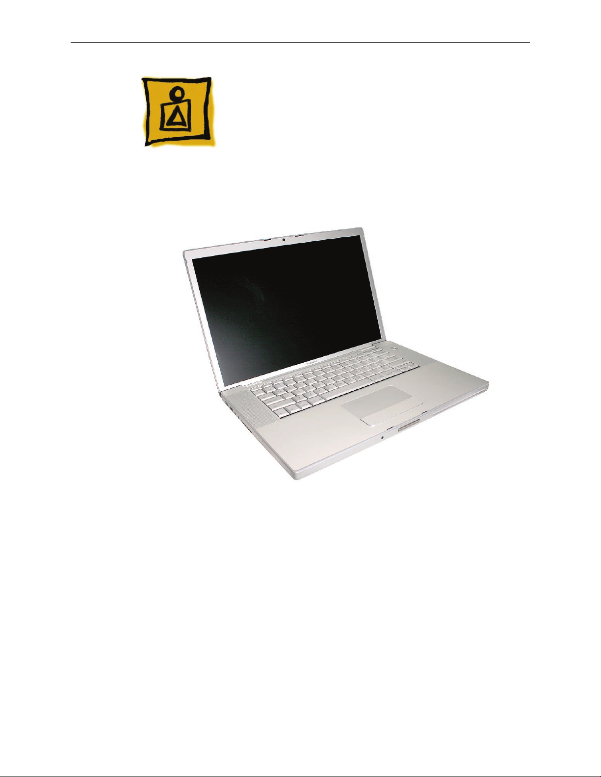
The MacBook Pro is the rst Mac notebook built upon the Intel Core Duo chip.
From the exterior, the MacBook Pro has a similar look to the previous aluminum PowerBook
notebook computers. However, as far as major part compatibility only the power cord and power
adapter AC plug are the same.
MacBook Pro Basics— General Information 6
Page 7

What’s New
Main service and feature differences from previous models:
Intel Core Duo microprocessor architecture: 1.83GHz, 2.0GHz, and a 2.16GHz option•
Higher resolution 15.4-inch display, 1440 x 960, 114 dpi (previously 1280 x 854, 101 dpi)•
Supports DDR2 memory up to 2GB•
128MB VRAM with dual link DVI option is now standard•
9.5mm slot load SuperDrive (versus the previous 12.7mm)•
80GB 5400 RPM hard drive standard•
100GB/120GB 5400 RPM, 100GB 7200 RPM hard drive option•
No modem•
No FireWire 800 port•
No PC Card slot•
ExpressCard/34 expansion card slot•
Dual display latch•
AirPort and Bluetooth cards and antennas are separate and in dierent locations•
The AirPort Extreme antenna assembly is in the clutch cover•
Infrared sensor•
iSight camera built in•
MagSafe magnetic power connector•
New Parts and Procedures
Main Logic Board
The major change is the Intel Core Duo design with the ATI Mobility Radeon x1600 graphics
chip. The FireWire 800 port and S-video connector has been removed. Composite and S-video
connection is still available using the optional Apple DVI to Video adapter. Clearly, this new logic
board will not t in any previous Mac notebook or vice versa.
The microprocessor is soldered to the main logic board. It is not upgradable.
To accompany these hardware changes, the boot architecture is now based on Extensible
Firmware Interface (EFI). EFI replaces the Open Firmware (OF). Services provide by OF such as
boot snag keys such as “C” for boot from optical, “N” for network boot, and “T” for Target Disk
Mode are still available under EFI. The one change is the “D” key is used to launch Apple Hardware
Test from the Mac OS X Install disc.
Main battery
MacBook Pro uses a new battery pack. It built with lithium polymer battery cells. This technology
is used with our iPod product line and the base chemistry is the same as the previous lithium ion
cells. This battery pack uses the same controller as the PowerBook G4 (15-inch Double-layer SD).
As such the battery calibration procedure is the same.
MacBook Pro Basics— General Information 7
Page 8
Power Adapter
The system was designed to use the new Apple 85-Watt Portable Power Adapter. This power
adapter comes with the new MagSafe power connector. It is not compatible with any previous
notebook computer.
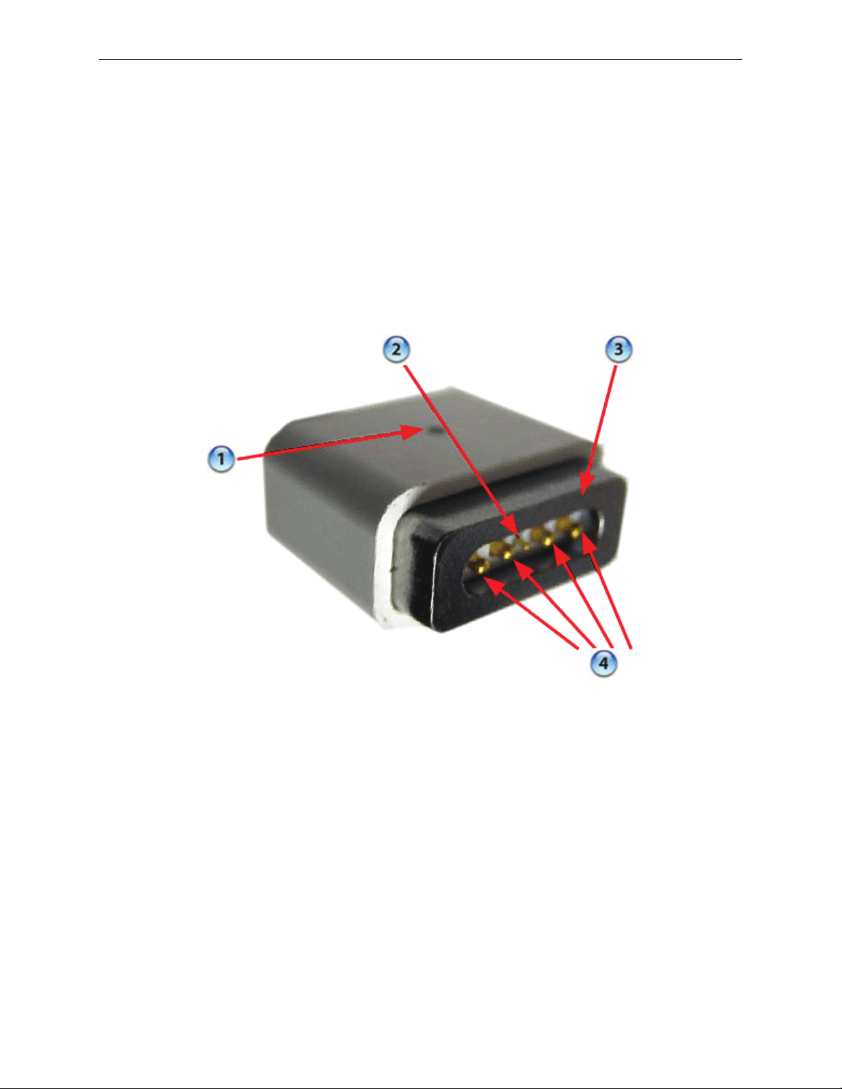
The MagSafe connector consists of a magnet and an attraction plate. The magnet is placed
within the computer. The attraction plate is part of the DC plug on the power adapter.
The DC plug consists of ve pins. Each pin is spring loaded. The center pin is a sense pin (2). This
center pin must make contact with the computer before power is applied. Power is carried on
the remaining four pins. The outer pins are positive terminals, the inner pair are the return paths.
The pin pairs to either side of the sense pin are redundant. As such, the plug can be put in two
ways. To support this design, the power LED (1) is on both side of the connector. The behavior of
the LED is the same as before, amber for charging the battery, green for supplying power, but not
to charge the battery.
MacBook Pro Basics— General Information 8
Page 9
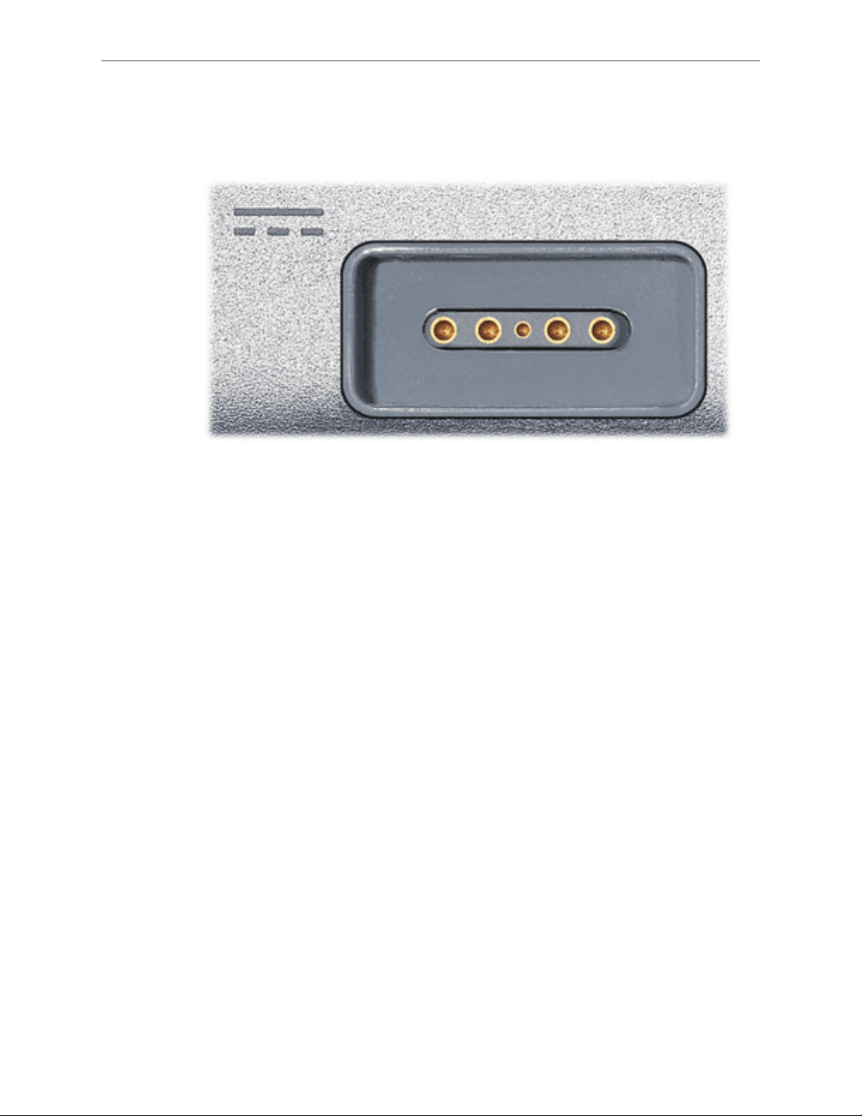
As the computer port has the magnet, as you are servicing the system it is recommended to
put a piece of tape over the connector to avoid materials such as screws and washers to be
inadvertently drawn into it.
15.4-inch Display
The MacBook Pro is the rst Mac notebook to the use the 15.4-inch size display. In addition, it
is the brightness display used. As such, care must be exercised to avoid damaging the display
panel. As you will see in the design, contact with the rear of the panel has been minimized. Do
not put any new material such as tape on the back of the display panel nor press hard on it while
handling it.
Top Case
As the sleep magnet has been relocated to the side of the display bezel, the sleep sensor is now
located to the right side of the top case just around the bottom of the perforated
Keyboard
The keyboard is the same design as shipped with the PowerBook G4 (15-inch/17-inch Double
Layer SD) except the ex cables. In particular, the keyboard backlight ex has changed. As such
no other internal keyboard is compatible with MacBook Pro.
Mass Storage (Hard drive and optical drive)
The hard drive has changed to a Serial ATA interface. This drive is new and previous PowerBook
drives will not work in this system.
The optical drive is a 9.5mm high drive. Previously optical drive has 12.7mm height. As with
previous designs, the drive should be at in its compartment before fastening it down. This step
ensures proper path for optical media to enter and exit the drive.
MacBook Pro Basics— General Information 9
Page 10
AirPort Extreme
The AirPort Extreme card is a new card design. Unlike the most recent card, it does not support
Bluetooth, It is the same form factor as used on the iMac (Spring 2006). However, there are two
version of these cards. We have structured our service parts to keep the two separate.
The AirPort antenna is no longer in the display housing. In the clutch barrel, there is a gray plastic
insert. The AirPort antenna is underneath this plastic window.
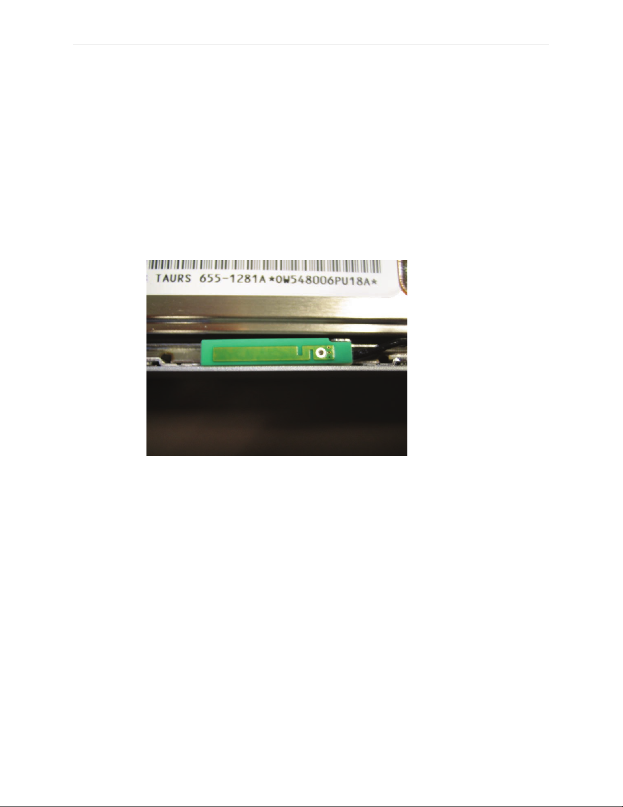
Bluetooth
Bluetooth has returned as a separate card. In addition, it has its own antenna. It is a little board
which is place in front of the hard drive near where the top case meets the bottom.
Back up battery
The back battery is no longer a rechargeable. It only provides power to the real time clock and
does not support system memory.
If you don’t have a power adapter connected, when you swap a battery in a running system, it
must be done from sleep. The system will shutdown when you remove the battery. When you
power back up, it will boot up from hiberation.
ExpressCard
ExpressCard has replaced the PCMCIA card cage. The ExpressCard standard supports two sizes
cards, 34mm and 54mm width. MacBook Pro supports the 34mm standard.
Unlike the previous PCMCIA design, there is no eject button. The card itself is used to engage and
disengaged itself from the card cage. In some designs like Ethernet ExpressCard, the card stick
out beyond the card cage. It is easy to push on the card to release it. Other cards will be ush
with the MacBook Pro enclosure and will take a little more care to pop out.
MacBook Pro Basics— General Information 10
Page 11
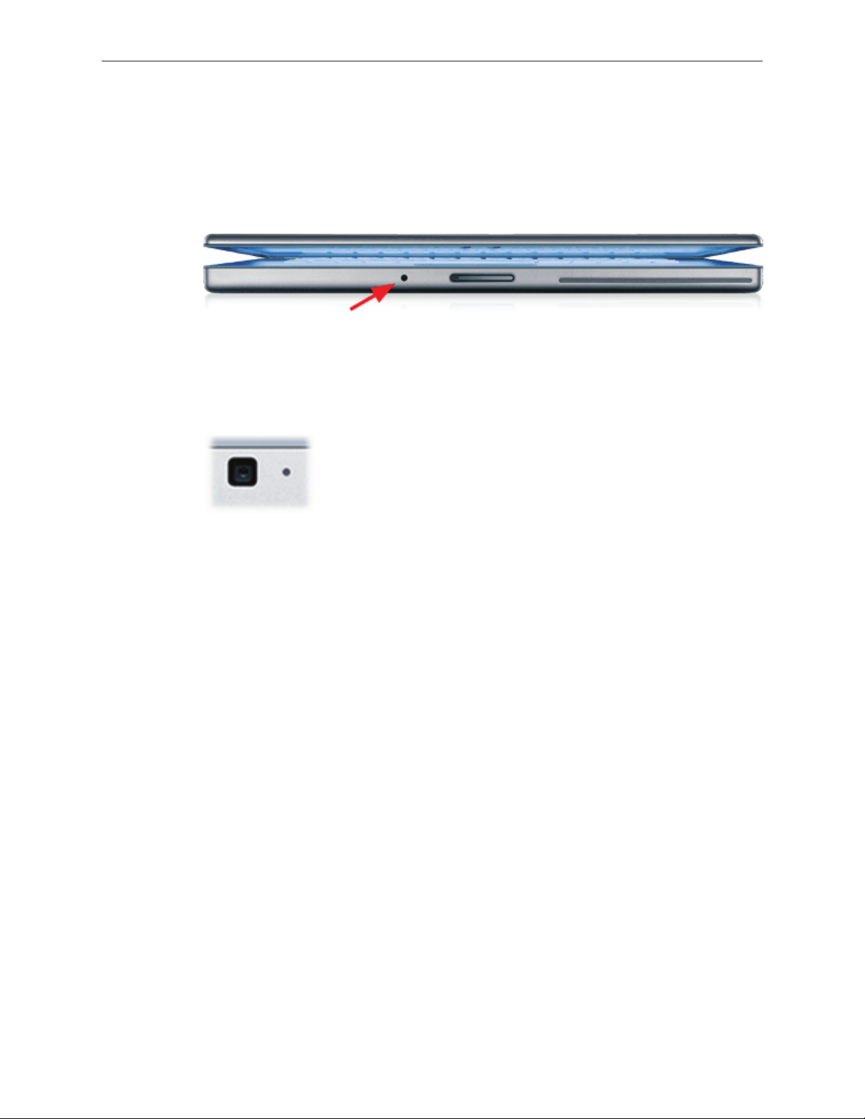
IR and the Apple Remote
Infrared port is placed on the front of the unit just to the right of the display latch button. This
port is used in conjunction with the Apple Remote provided with each unit. It can be used to
control Front Row software that manages your music, photos and videos. The remote can also be
used to control other applications as well.
iSight Camera
An iSight Camera has been built-in into the display bezel. It allows a user to capture video and
take still photos. The green LED to the right of the camera is on when the camera is on.
Unlike the standalone iSight camera, the microphone is not integrated with the camera. It is
located as previous Mac notebooks by left speaker.
MacBook Pro Basics— General Information 11
Page 12
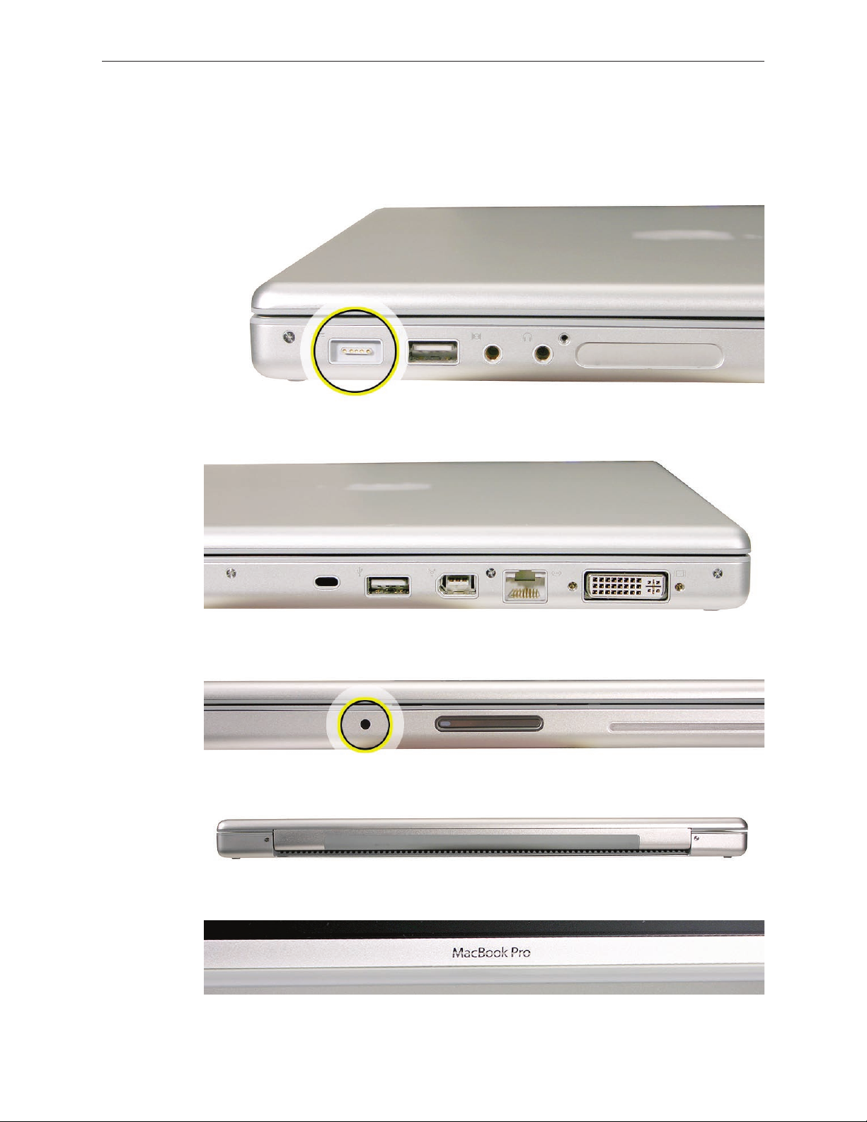
Identifying the MacBook Pro
Below are views of the MacBook Pro, with identifying features.
Left side: MagSafe™ magnetic power connector.
Right side: No FireWire 800 port.
Front: Infrared sensor window.
Rear: Grey antenna window in the clutch cover.
Display bezel: MacBook Pro.
MacBook Pro Basics— General Information 12
Page 13
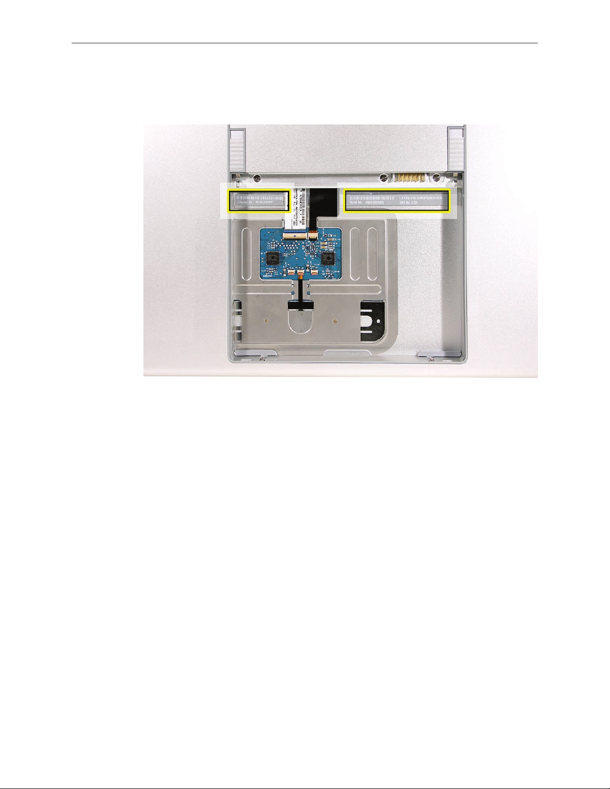
Serial Number and Ethernet ID
The Serial Number and Ethernet ID are located in the battery bay.
Tools
This procedure requires the following tools:
Clean non-marring work surface•
ESD wrist strap and mat•
Multi-compartment screw tray (such as a plastic ice cube tray)•
#0 Phillips screwdriver (magnetized)•
#1 Phillips screwdriver (magnetized)•
Torx T6 screwdriver (magnetized)•
4 mm socket wrench•
Black stick (nylon probe 922-5065) (or other non-conductive nylon or plastic at-blade tool•
Razor knife•
Needle-point metal probe•
Needlenose pliers•
Tweezers•
Kapton tape (922-1731 (0.5-inch x 12-yard roll))•
Thermal grease (922-7144)•
Gasket kit (076-1206)•
Alcohol pads•
Fine-point felt-tip permanent marker•
Putty knife tool (922-6761)•
Apple Pro keyboard and mouse (for troubleshooting)•
MacBook Pro Basics— General Information 13
Page 14

Electrostatic Discharge (ESD)
Use a properly grounded ESD wrist strap and mat when working on the inside of the computer.
Service Manual Note
In this manual, graphics or photos are intended to help illustrate procedures or information only,
and may show dierent levels of disassembly, board colors, congurations, or computer models,
than your computer.
Kapton® Tape Note
Kapton tape is used to secure cables and connectors where necessary.
During disassembly, note any Kapton tape use and locations—reapply in the same manner. Do
not over apply or build up tape on top of old tape; space tolerances are tight and build up or
extraneous use of tape may cause pressure on other components.
Cable Routing Note
The MacBook Pro matches the same one-inch enclosure height established with the PowerBook
G4 17-inch series of systems. More so than ever, the placement of parts and wiring is critical.
During disassembly, note cable routing. Reassemble in the same manner. Verify that cables do
not route over components when they should route into lower positions or channels. Verify that
the cables are not strained or applying pressure onto other components.
Screw Measurement Note
All screw measurements given are the specied full length. Actual measured lengths may vary.
MacBook Pro Basics— General Information 14
Page 15

Service Source
Take Apart
MacBook Pro
© 2006 Apple Computer, Inc. All rights reserved.
Page 16
Foot
Tools
This procedure requires the following tools:
Foot kit•
Tweezers or needlenose pliers•
Soft cloth•
Preliminary Step
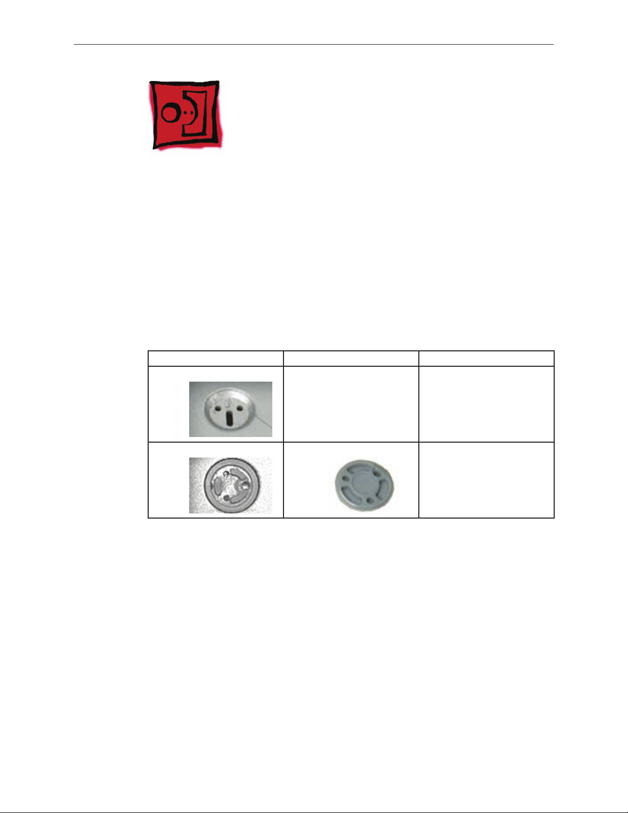
Before you begin, check the foot location that needs replacement and verify that the case plug is
attached. Also verify that the case plug, and the case foot in the kit, match the pictures below.
Plug Area on Bottom Case Matching Foot Action
Missing case plug Not available for replacement Replace the bottom case, or
send to Apple Repair Center.
Case plug Case foot Continue with the procedure,
matching the foot to the plug
on the bottom case.
MacBook Pro Take Apart — Foot 16
Page 17
Procedure
Warning: The glue used in this procedure can bond instantly to skin. Do not touch the glue.
In the event of contact, review the safety instructions at the end of this document. For
additional information, refer to the glue manufacturer:
Elmer’s Products, Inc.
Columbus, OH. 43215-3799
www.krazyglue.com
Place the computer upside down on a clean, lint-free cloth or other nonabrasive surface.1.
Select a foot from the kit. Verify that the case plug and case foot match (refer to the images 2.
shown in the table). Do not use a foot that does not match.
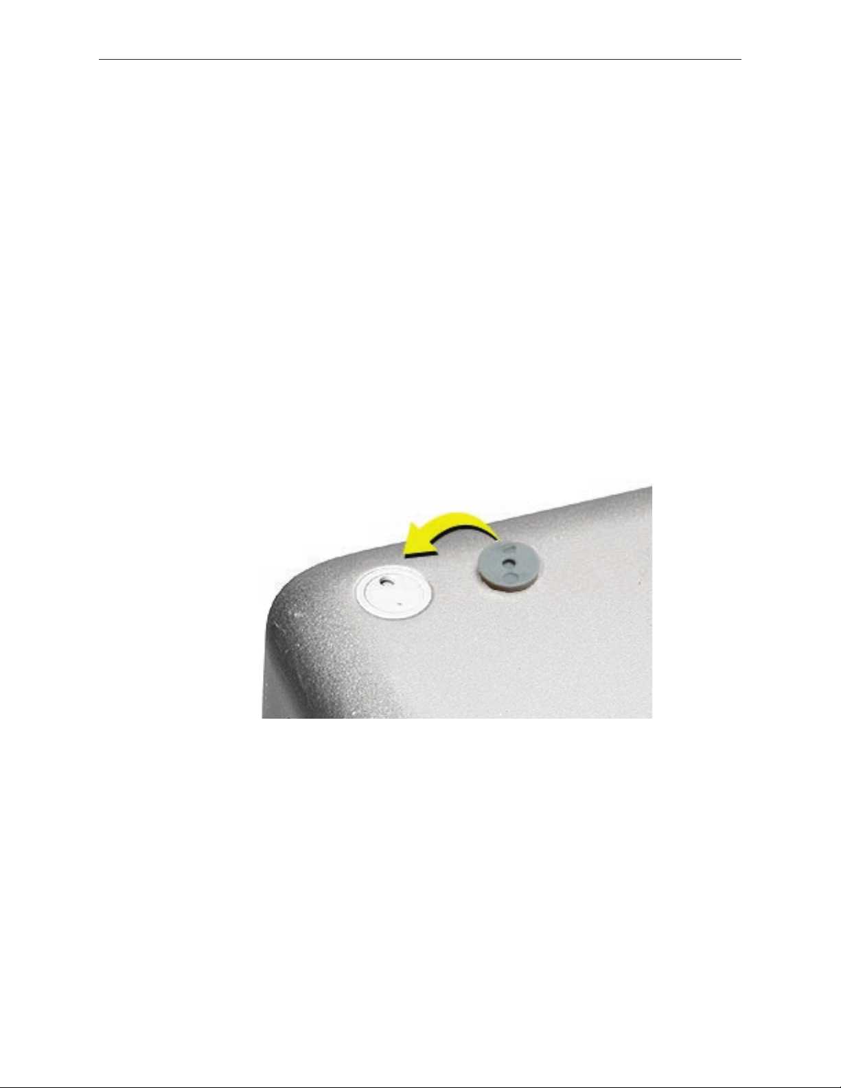
Make sure the plug area on the bottom case is clean. If any portion of the soft rubber foot 3.
remains, remove it so that only the hard plastic plug is visible.
Important: When positioning the foot, make sure the indents and bumps of the rubber foot
match up and t into the corresponding indents and bumps in the plug. This ensures a
balanced and level tting. (Note: The picture below is of a dierent foot than on the
computer, and is for illustration only.)
MacBook Pro Take Apart — Foot 17
Page 18
4. Warning: GLUE IS AN EYE AND SKIN IRRITANT. BONDS SKIN INSTANTLY. Do not touch the
glue at any time. Before opening the glue, review the safety instructions at the end of
this document.
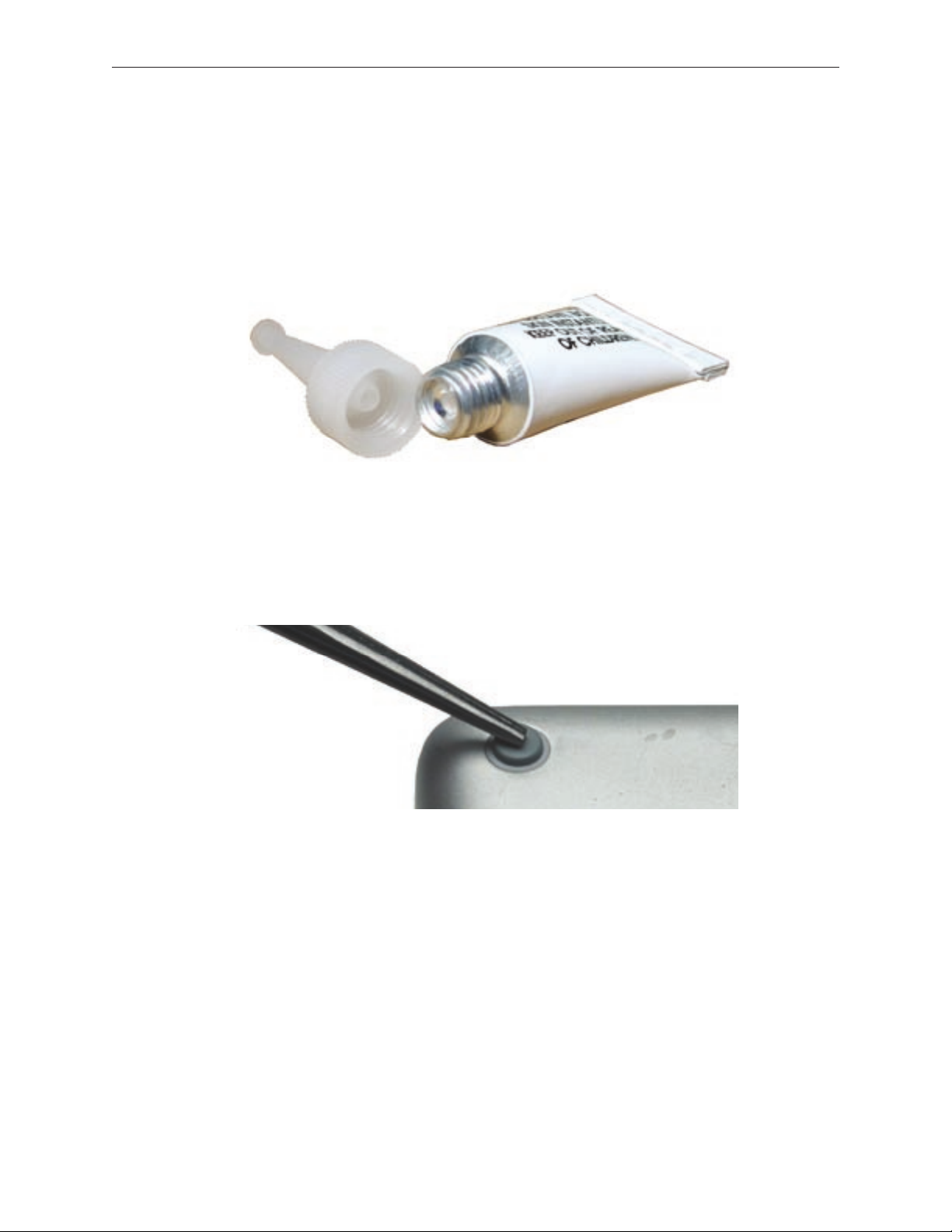
Important: The glue tube included in the kit is sealed until rst use. Do not break the seal
until you are ready to use the glue. To break the seal, hold the tube upright and away from
you. Place the hollow nozzle cap on the tube and tighten it all the way down. The tube is
then ready to dispense the glue through the nozzle cap.
Apply one drop of glue to the plug on the bottom case. Do not spread the glue.5.
Using tweezers or needlenose pliers, carefully position the new foot so its textured surface 6.
ts into the inner ring of the plug.
Using the end of the tweezers or pliers—not your nger—lightly press and hold the foot in 7.
place for 30 seconds.
Before turning over the computer, allow the glue to set for at least 15 minutes.8.
Discard the tube of glue.9.
SAFETY INSTRUCTIONS: GLUE IS AN EYE AND SKIN IRRITANT. BONDS SKIN
INSTANTLY. Contains ethyl cyanoacrylate. Avoid contact with skin and eyes. If eye or mouth
contact occurs, hold eyelid or mouth open and rinse thoroughly but gently with water only for 15
minutes and GET MEDICAL ATTENTION. Liquid glue will sting eye temporarily. Solidied glue
may irritate eye like a grain of sand and should be treated by an eye doctor. If skin bonding occurs,
soak in acetone-based nail polish remover or warm soapy water and carefully peel or roll skin
apart (do not pull). Contact through clothing may cause skin burn. If spilled on clothing, ush with
cold water. Avoid prolonged breathing of vapors. Use with adequate ventilation. KEEP OUT OF
REACH OF CHILDREN.
MacBook Pro Take Apart — Foot 18
Page 19

Battery
Tools
This procedure requires the following tools:
Clean non-marring work surface•
Preliminary Steps
Warning: Always shut down the computer before opening it to avoid damaging its internal
components or causing injury. After you shut down the computer, the internal components
can be very hot. Let the computer cool down before continuing.
Part Location
MacBook Pro Take Apart — Battery 19
Page 20
Procedure
Warning: If the computer has been recently operating, allow it to cool down before
performing this procedure.
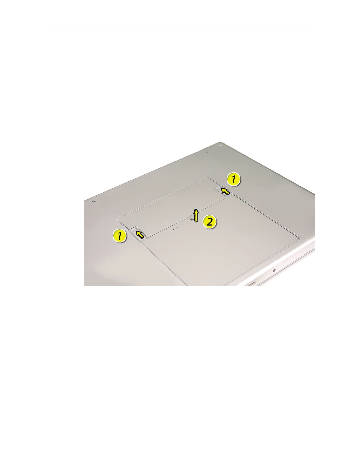
Shut down the computer.1.
Disconnect the power cord and any other cables connected to the computer.2.
Place the computer face down.3.
Slide both battery latches away and lift the battery out of the battery bay.4.
MacBook Pro Take Apart — Battery 20
Page 21
Memory
Tools
This procedure requires the following tools:
#0 Phillips screwdriver (magnetized)•
Clean non-marring work surface•
ESD wrist strap and mat•
Preliminary Steps
Before you begin, remove the following:
Batter• y
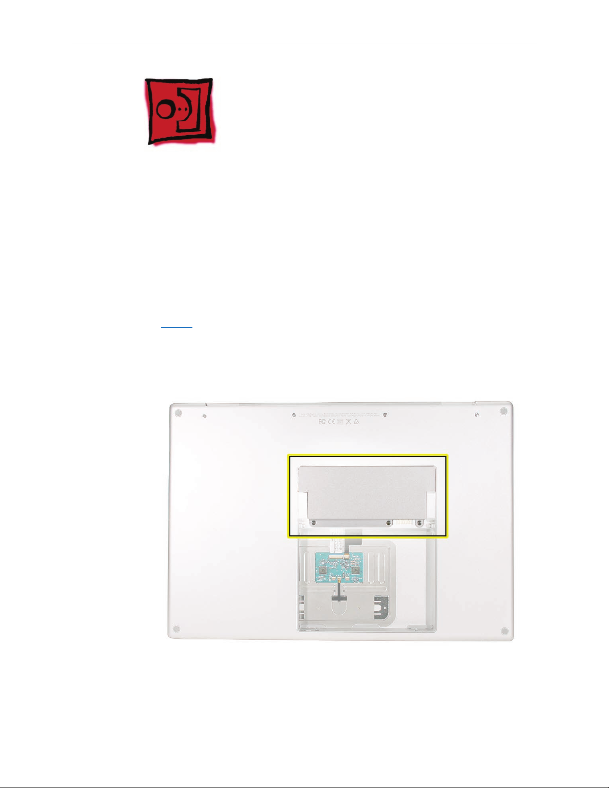
Part Location
MacBook Pro Take Apart — Memory 21
Page 22
Procedure
Warning: If the computer has been recently operating, allow it to cool down before
performing this procedure.
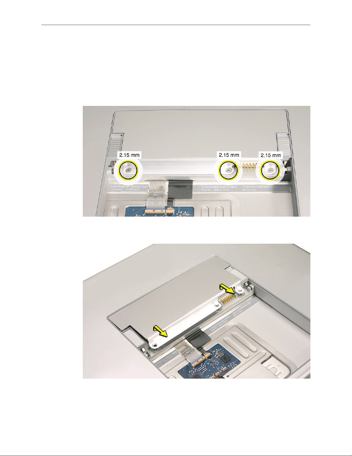
Place the computer face down.1.
Remove the three screws from the memory door. 2.
Remove the door, as shown. 3.
Notes:
• If only one memory card is installed, the factory installs it in the bottom memory slot.
• Memory must be removed from the top slot before removing from the bottom slot.
MacBook Pro Take Apart — Memory 22
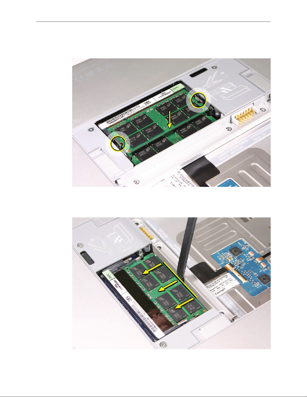
Page 23
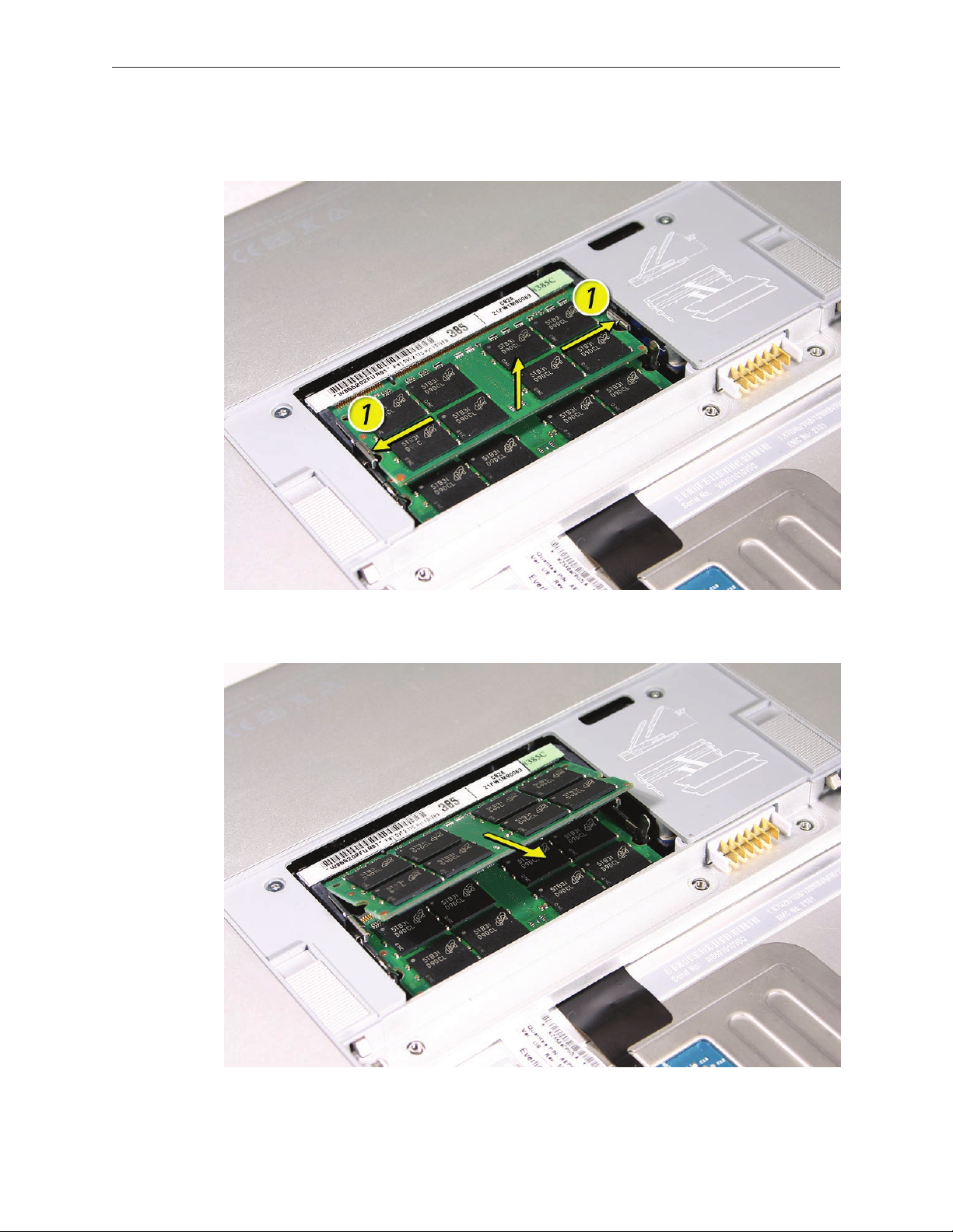
To remove memory cards, carefully spread the two locking tabs for the slot (top or bottom) 4.
away from the card on both sides and allow the card to pop up slightly.
Pull the card straight back and out of the memory slot. 5.
MacBook Pro Take Apart — Memory 23
Page 24
Replacement Procedure
Notes:
DDR memory cards do not t in this slot (dierent notch location).•
If installing two cards, install into the bottom slot rst.•
When nished installing memory into the bottom slot, use a black stick leveraged against •
the frame to push the back of the card toward the slot to verify that the card is rmly seated.
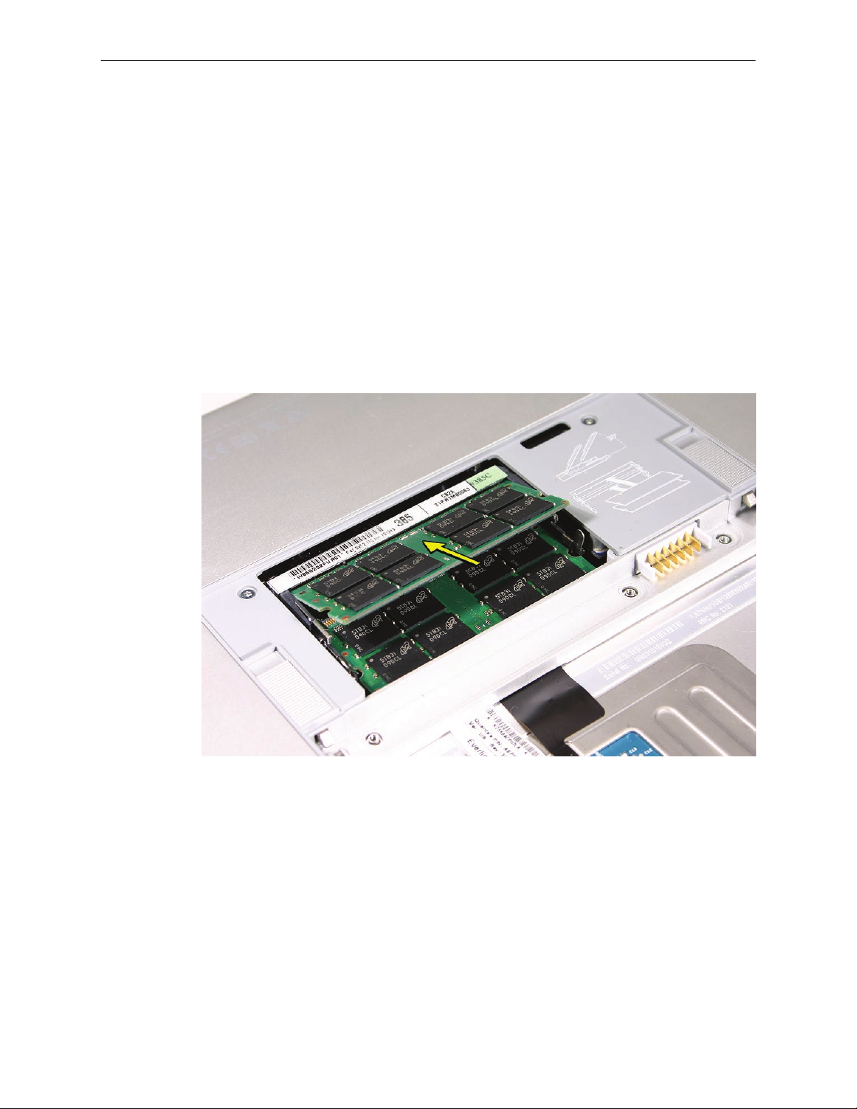
Align the notch in the memory card with the tooth in the slot before inserting.•
To install a memory card, insert the card at a 25-degree angle behind the locking tabs of the 1.
top slot.
Firmly push the card straight into the slot until it is fully and securely seated along its length. 2.
Note: If the back of the card drops down before it is fully seated, raise it up enough to push
it fully into the slot.
MacBook Pro Take Apart — Memory 24
Page 25
When the card is fully seated, push the card straight down until the tabs click onto both 3.
sides of the card, locking it into place.
To ensure that the memory cards are fully and securely seated, for the lower card, use a black 4.
stick leveraged against the frame to evenly push along the back of the card.
MacBook Pro Take Apart — Memory 25
Page 26
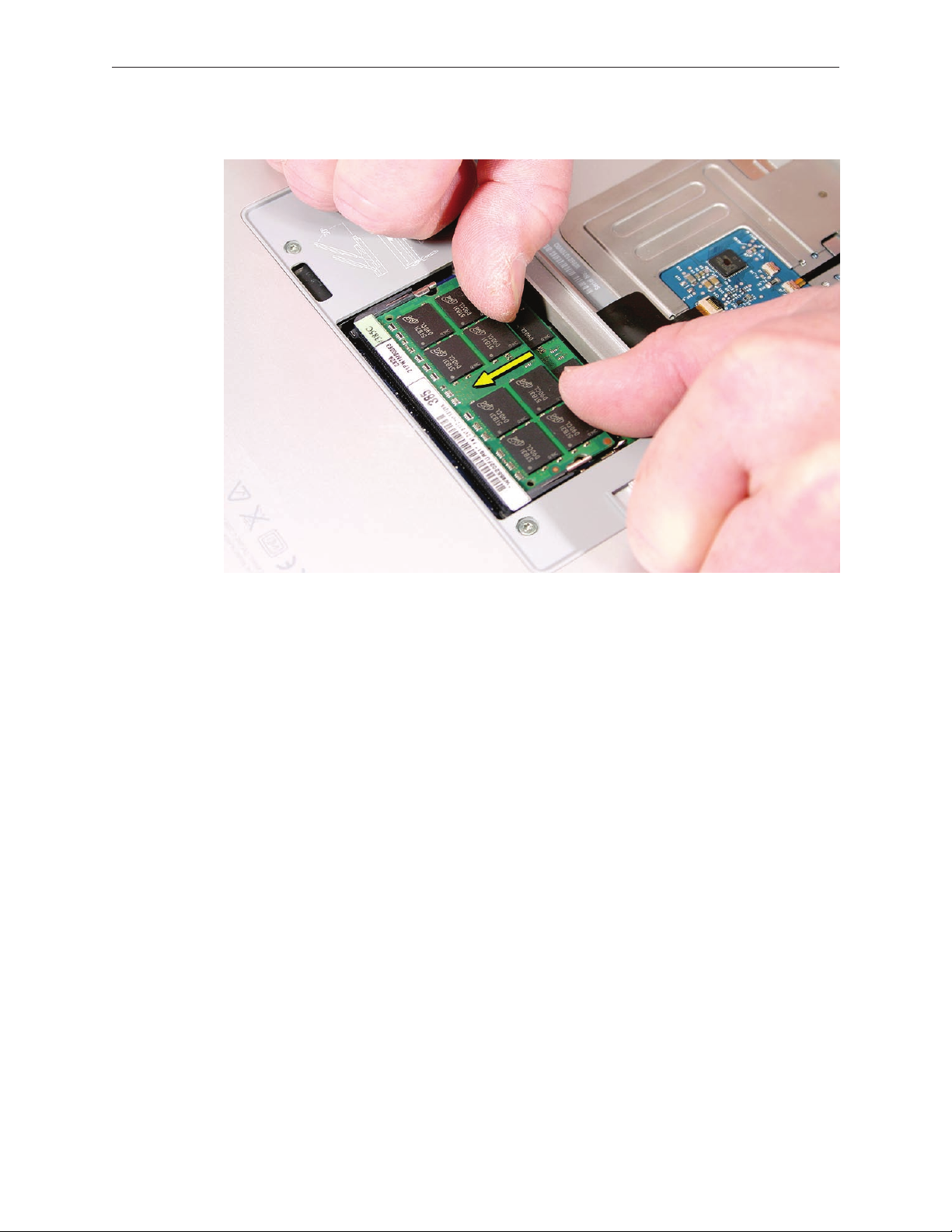
For the upper memory card, push with your thumbs to verify the card is fully seated. 5.
Check that the cards are secured by the brackets on both sides.6.
Install the memory door.7.
Replace the battery.8.
Use Apple System Proler to verify that the memory is recognized. (Choose the menu 9.
bar Apple logo () > About This Mac, click More Info..., select the System Prole tab,
open the Memory Overview.)
MacBook Pro Take Apart — Memory 26
Page 27
Top Case
Tools
This procedure requires the following tools:
#0 Phillips screwdriver (magnetized)•
Torx T6 screwdriver (magnetized)•
Black stick (nylon probe 922-5065) (or other non-conductive nylon or plastic at-blade tool•
Multi-compartment screw tray (such as a plastic ice cube tray)•
Preliminary Steps
Before you begin, remove the following:
Batter• y
Memory Doo• r
Part Location
MacBook Pro Take Apart — Top Case 27
Page 28
Procedure
Notes:
If replacing the top case, once the top case is removed, use a razor knife to carefully lift and •
transfer the Serial Number and Ethernet ID labels to the replacement top case.
This procedure removes the top case and keyboard assembly. The keyboard is removable •
only after removing the top case.
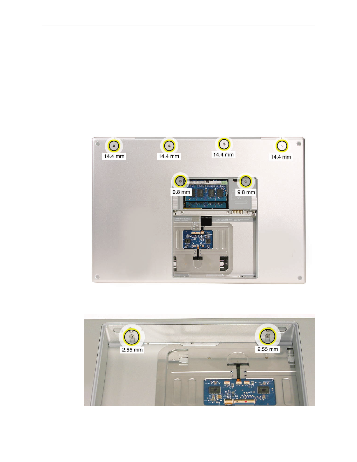
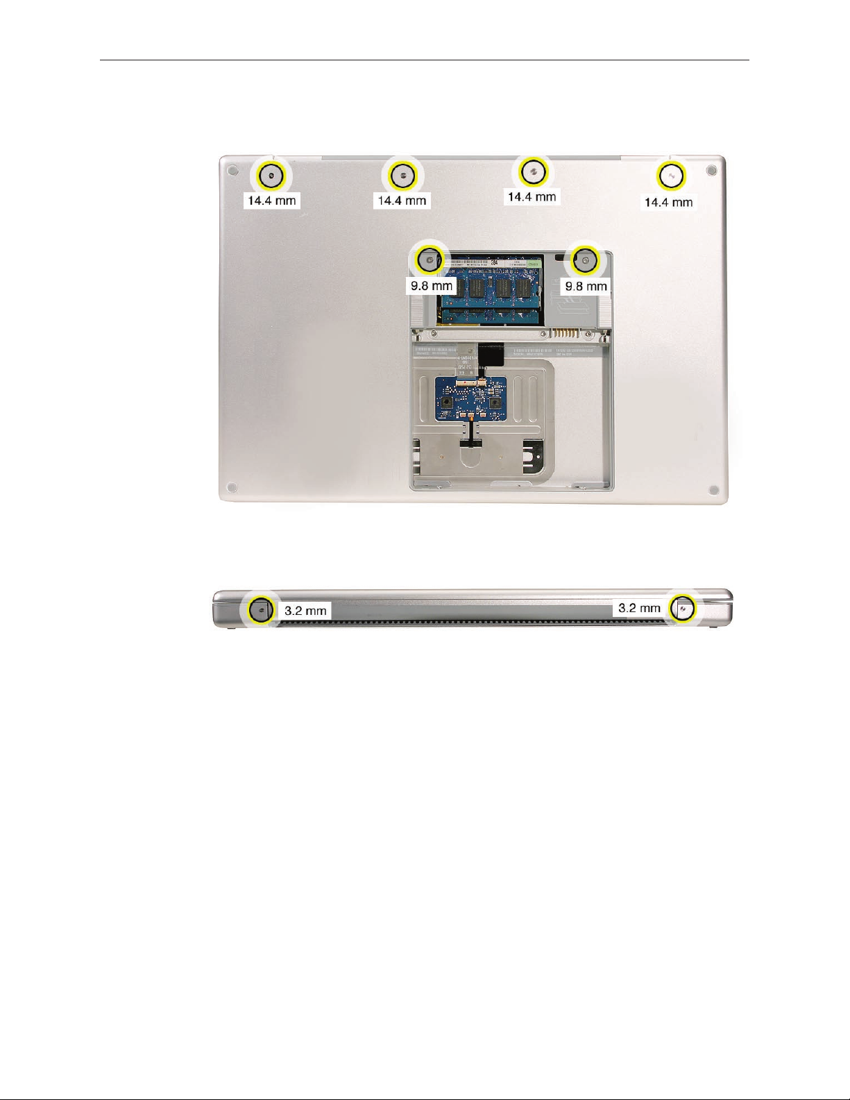
Place the computer upside down.1.
2. Remove the six screws shown.
3. Rotate the computer and remove the two screws along the front of the battery bay.
MacBook Pro Take Apart — Top Case 28
Page 29
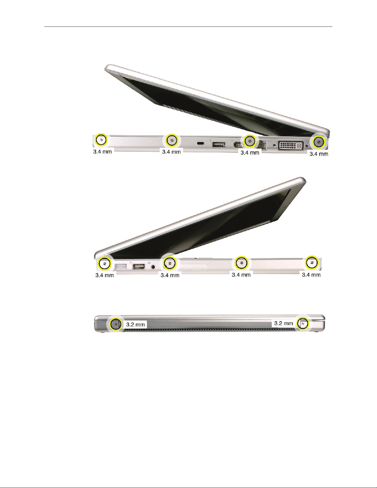
4. Remove the four screws from each side.
5. Remove the two screws from the back edge.
.
MacBook Pro Take Apart — Top Case 29
Page 30
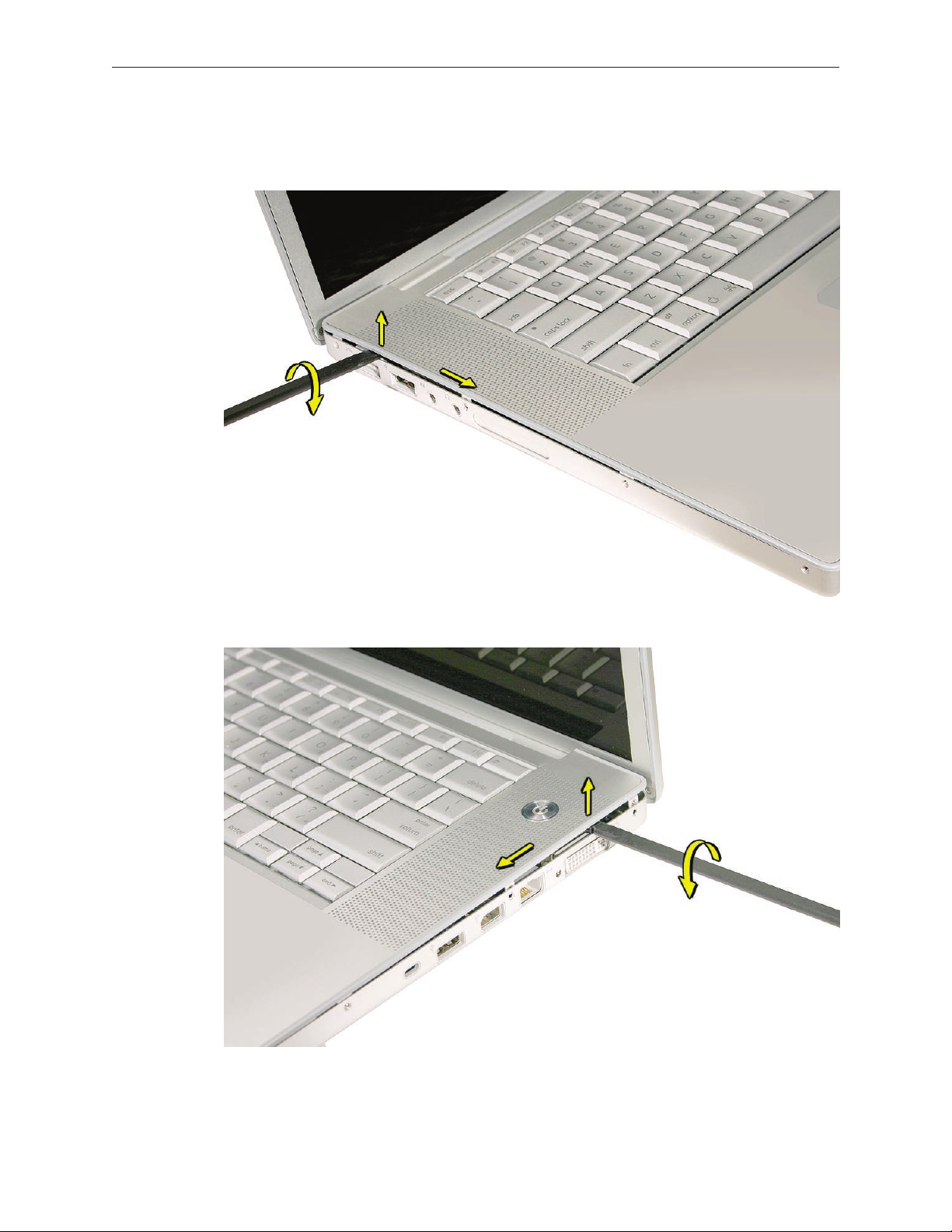
Face the computer forward and open the display slightly past 90-degrees. 6.
Use a black stick to loosen the top case along the rear of the left and right sides. 7.
MacBook Pro Take Apart — Top Case 30
Page 31
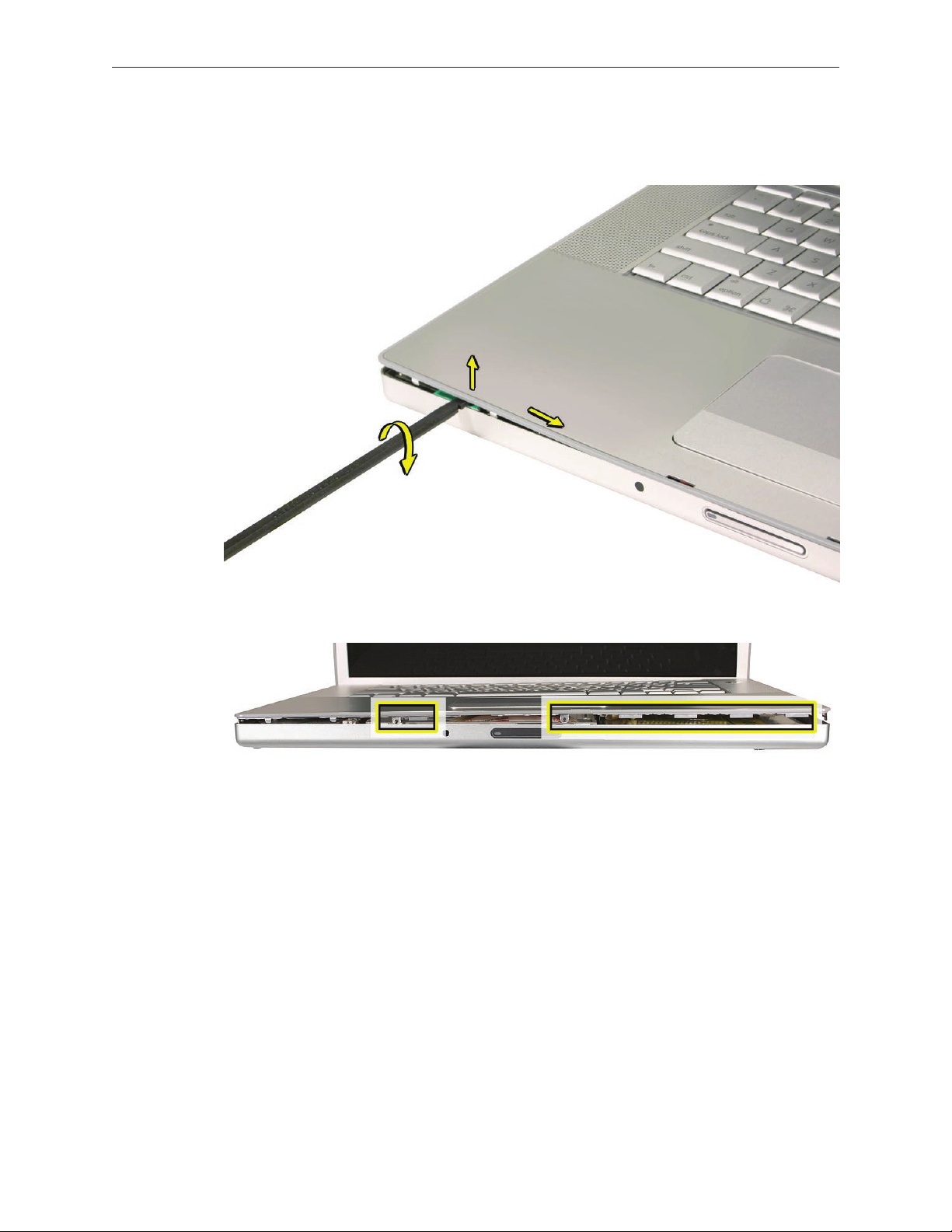
Along the front, start at the left and slowly encourage the snaps and screw tabs (shown in 8.
graphic below) to release as you move right. A snapping noise as the snaps release is normal.
Important: Do not lift the case once it is free—it is still connected to the bottom case by the
keyboard ex cable.
MacBook Pro Take Apart — Top Case 31
Page 32

Important:9. To avoid bending screw tabs along the back edge of the top case, lift the top
case slightly so that it does NOT touch the bottom case, then rotate the front of the case up
and back until you can disconnect the keyboard ex cable from the logic board.
MacBook Pro Take Apart — Top Case 32
Page 33

Replacement Procedure
Note: If replacing the top case, remove the keyboard and transfer to the replacement top case.
Visually check to verify that all cables are connected and routed correctly with nothing raised 1.
up or incorrectly over a component.
Check perimeter wiring and cables around clutches to verify that they will not be caught or 2.
pinched by the top case during replacement.
On the computer, verify that all cables are secure and lay at.3.
On the top case, check cable connections and routing. 4.
MacBook Pro Take Apart — Top Case 33
Page 34

Check that the perimeter screw tabs and ribs are not bent. 5.
Note: The metal can quickly fatigue and break o. Be extremely careful to gently straighten
tabs, if needed.
Verify that the plastic spacer is on the front screw tab, shown. 6.
MacBook Pro Take Apart — Top Case 34
Page 35

Verify that the screw tabs in back are straight and guide them inside the bottom case. Work 7.
your way around guiding the screw tabs into the bottom case along both sides.
If the back screw tabs are bent out, straighten by pressing the edge of the case on a hard at 8.
surface and rolling to vertical.
MacBook Pro Take Apart — Top Case 35
Page 36

Any screw tabs that are not straight will not t or accept screws correctly. 9.
Use your nger and a black stick to carefully straighten bent screw tabs. 10.
MacBook Pro Take Apart — Top Case 36
Page 37

Connect the ex cable from the top case to the logic board.11.
Lift the top case o the bottom case slightly and rotate it down (verify that the keyboard 12.
cable stays connected and is folding properly) and align the corners.
Carefully pull or push tabs slightly, if needed. 13 . Note: Guarded, controlled pushing with your
thumb may be helpful to nesse the tabs into place.
The two front screw tabs may need to be guided with a black stick through the battery bay.14.
Squeeze at the snap locations (shown below) along the front edge of the top case to verify 15 .
that the they are seated. The top case should lay at along all sides and top, if not, make sure
that cables and components are not interfering.
Reinstall the left and right side screws.16.
Important: Do not insert screws into the DVI port screw holes. If they get stuck, it may
require removing the logic board to dislodge.
MacBook Pro Take Apart — Top Case 37
Page 38
Install the bottom screws and the two screws near the memory. 17.
Install the two screws along the back18. .
.
MacBook Pro Take Apart — Top Case 38
Page 39

Install the two screws in the battery bay. 19.
Important: For the screw shown, push in the display latch button while installing the screw.
Install the memory door and replace the battery. 20.
Testing the computer should include:21.
Powering on, checking the keyboard and trackpad function. •
Operate the computer in a darkened room to check for keyboard backlight function.•
MacBook Pro Take Apart — Top Case 39
Page 40

Keyboard
Tools
This procedure requires the following tools:
#0 Phillips screwdriver (magnetized)•
Black stick (nylon probe 922-5065) (or other non-conductive nylon or plastic at-blade tool•
Preliminary Steps
Before you begin, remove the following:
Batter• y
Top Cas• e
Part Location
MacBook Pro Take Apart — Keyboard 40
Page 41

Procedure
Important Notes:
The MacBook Pro keyboards are not interchangeable with previous models. Verify that the •
correct replacement keyboard is ordered, and/or top case if replacing.
The keyboard comes as a multi-layered assembly, and includes backlighting. Do not •
disassemble the keyboard assembly. Dust, ngerprints, or misalignment, can cause improper
function and damage.
On a clean at surface, turn the top case upside down.1.
Locate the protective cover over ex cable connectors. 2.
MacBook Pro Take Apart — Keyboard 41
Page 42
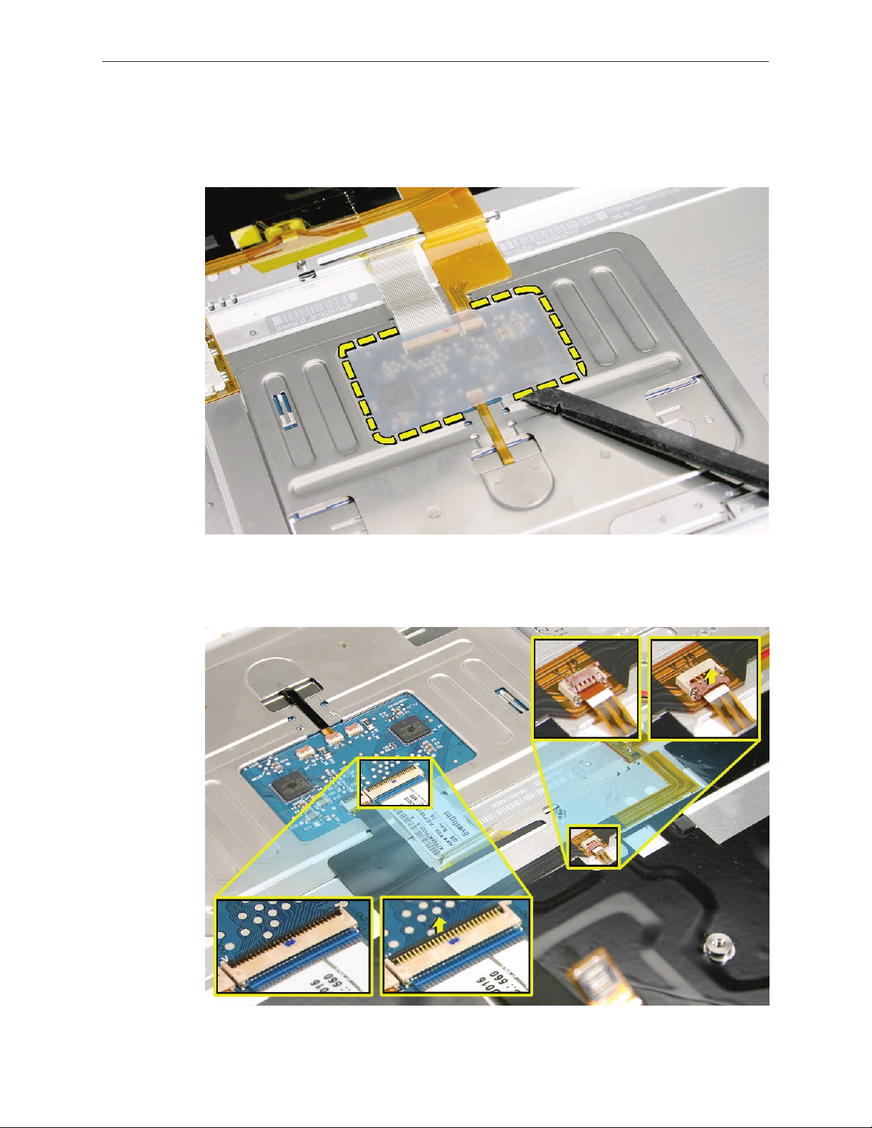
Carefully slide a black stick around the perimeter of the cover to release the adhesive.3.
Lift o the cover and set aside for reassembly. 4. Important: Keep the cover and any residual
adhesive on the top case clean.
Rotate the top case and locate the two keyboard ex connectors shown below. Remove any 5.
Kapton tape, then very carefully lift the latches of the connectors to release the cables.
Important: The connectors are delicate. If damaged, the top case must be replaced.
MacBook Pro Take Apart — Keyboard 42
Page 43
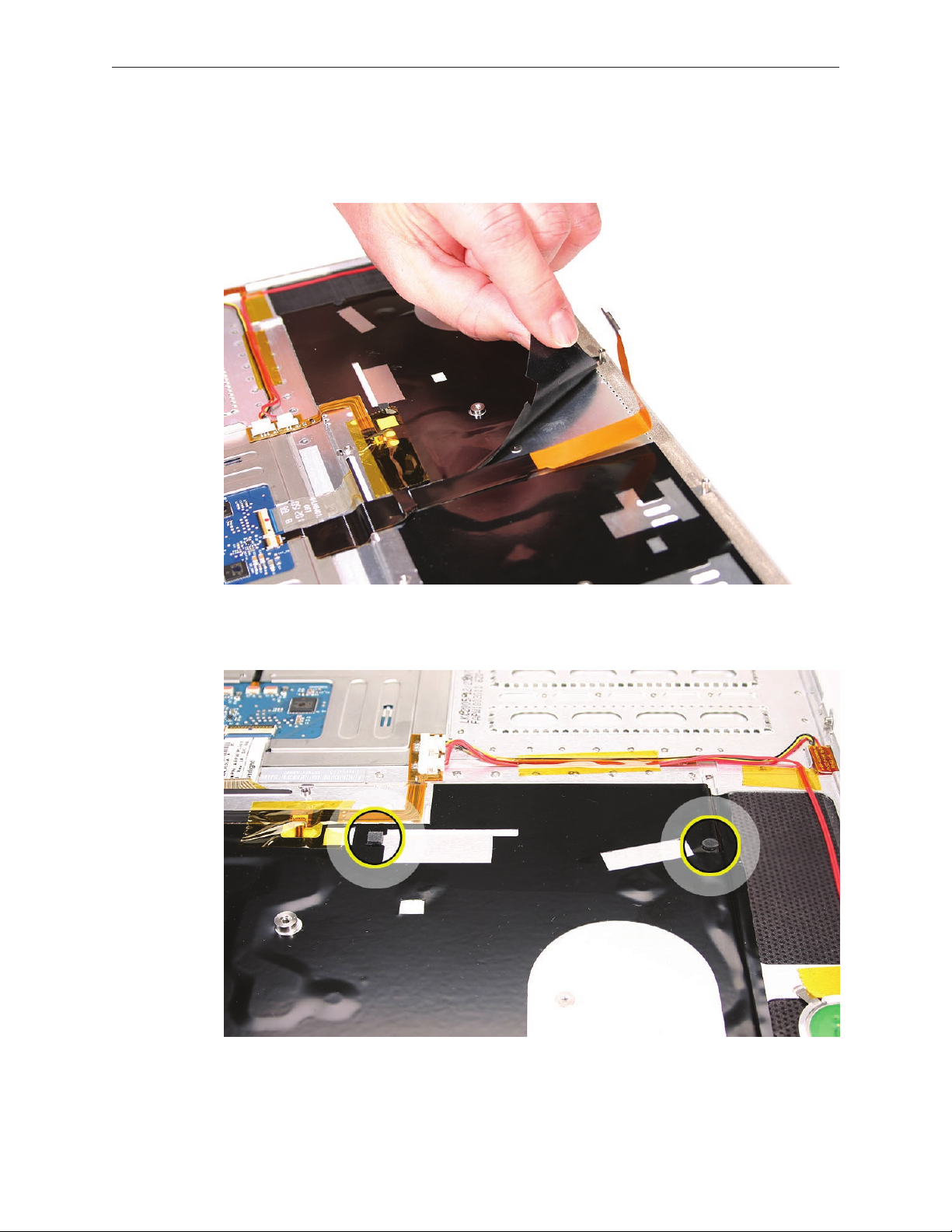
Note the positioning, then carefully peel o the insulator lm covering the back of the 6.
keyboard well. Reserve the lm and keep it clean for reinstallation.
Important: Use care at notches and narrow parts to avoid ripping the lm.
Important: Do not remove the rubber pads if not replacing the top case. If replacing the top
case, transfer these to the same locations.
MacBook Pro Take Apart — Keyboard 43
Page 44

Use needlenose pliers to straighten the four bend-tabs located along the bottom edge, as 7.
shown. These tabs lock down and stien the top edge of the keyboard. Important: The
bend-tabs are delicate. Bend them carefully to avoid damage. Avoid over-bending.
Remove the ten keyboard screws. 8.
MacBook Pro Take Apart — Keyboard 44
Page 45

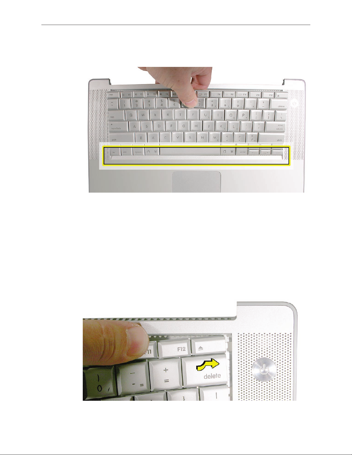
Note the six insert-tabs along the middle edge, and two on each side. The following 9.
procedures release these tabs so that the keyboard can be removed.
To prevent the keyboard from falling out, support it with your hand, and raise the top case 10.
up vertically. Note: The keyboard does not have adhesive under it, as in previous models.
MacBook Pro Take Apart — Keyboard 45
Page 46
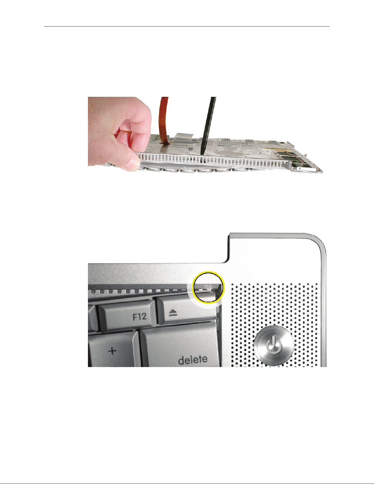
If needed, push through one of the top center keyboard screw holes, with the point of a 11.
black stick, to bow out the keyboard slightly.
Important: Ensure that the hole used is a screw hole, or damage to other sensitive
components may result. A black stick is used to avoid damaging the screw boss threads—do
not use a metal tool.
Important:12. During this procedure, do not allow the tabs or metal edge of the keyboard to
scrape along the cosmetic surface of the top case, or damage can result.
MacBook Pro Take Apart — Keyboard 46
Page 47
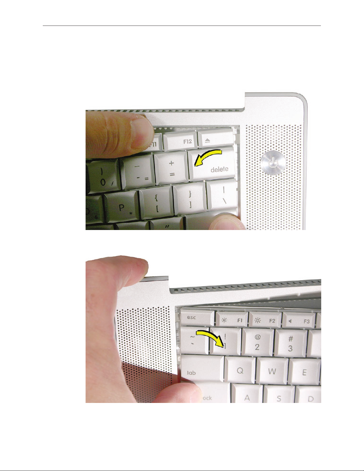
Use your nger to hold the bowed out keyboard. Continue to bow it out only enough for the 13 .
tabs on one side of the keyboard to release cleanly. Repeat for the other side.
Important: Do not bow the keyboard too much, or it may become permanently bent.
MacBook Pro Take Apart — Keyboard 47
Page 48

Lift the keyboard up to release the tabs along the bottom edge and carefully thread out the 14.
ex cables.
MacBook Pro Take Apart — Keyboard 48
Page 49

Replacement Procedure
When replacing the keyboard, here are some key points to ensure:
Prevention of scratches to the cosmetics of the top case•
All tabs are properly seated•
Keyboard lays at•
Cables not caught•
Bend-tabs are not damaged•
Screw holes align•
Cable connectors are not damaged and cables are secure•
Kapton tape is applied as before•
Insulator lm is correctly installed•
Before replacing or installing a replacement keyboard, verify that the four bend-tabs along 1.
the bottom edge of the keyboard, are straight and parallel with the bottom edge (two are
shown close-up, below).
Important: Do not bend any other bend-tabs on the keyboard other than the four along the
bottom. Other tabs hold the keyboard assembly together.
MacBook Pro Take Apart — Keyboard 49
Page 50

Guide the keyboard’s ex cables through the slot in the top case, as shown. Make sure that 2.
they do not catch or bend behind the keyboard.
Verify that the small cable routes through the slot, as shown. 3.
MacBook Pro Take Apart — Keyboard 50
Page 51
Lower the keyboard and seat all six tabs along the bottom, so that the keyboard sits at and 4.
straight.
Important: During the next steps, do not allow the tabs or metal edge of the keyboard to
scrape along the cosmetic surface of the top case, or damage can result.
While ensuring that the keyboard bottom stays straight and secure, hold the top of the 5.
keyboard in the middle, then with your other hand, bow in one side of the keyboard to
engage the two tabs at the top into the top case.
Important: Do not bow the keyboard too much, or it may become permanently bent.
MacBook Pro Take Apart — Keyboard 51
Page 52

Use the heel of your hand to hold in place the edge of the keyboard that was just inserted 6.
while holding the top of the keyboard with a nger on that hand, then use your other hand
to help bow in the remaining side of the keyboard until it can be engaged.
MacBook Pro Take Apart — Keyboard 52
Page 53

While supporting the keyboard in the top case, verify that the keyboard lays at and that all 7.
the tabs have seated properly.
Note: The keyboard will not sit at if any of the tabs have not seated properly. If the side tabs
are not seating or are binding, check the bottom edge of the keyboard to verify that all the
tabs are seated and the bottom of the keyboard is straight.
Verify that the bend-tabs are not caught.8.
Lay the top case at, and upside down. 9.
Pull on the ex cables to verify that they are not bent or caught under the keyboard, and 10.
that they extend to their connectors.
Verify that the screw holes align with the screw bosses and install all ten keyboard screws, 11.
starting from the middle and work out.
Bend the four bend-tabs over the metal of the bottom case to secure the bottom edge of 12.
the keyboard.
Important: The bend-tabs are delicate. Bend them carefully to avoid damage and no more
than 90-degrees, or to, or within, any etch marks, if present. Avoid over bending.
MacBook Pro Take Apart — Keyboard 53
Page 54

Insert the two ex cables into their connectors and secure. Verify that the cables are fully 13 .
inserted and secured straight. Kapton tape will be applied to the small connector, later.
Reinstall the protective cover over the area shown. Line up the edges carefully with the 14.
residual adhesive, then carefully burnish down the edges to secure. (top case shown rotated)
MacBook Pro Take Apart — Keyboard 54
Page 55

Replace the insulator lm in the same locations as they were removed. Ensure the holes in 15 .
the lm match up correctly with the screw bosses. Avoid wrinkles and bulges. If installing a
replacement top case, use the new lm if supplied.
Important: The lm must be installed and in the same location to protect against contact
and electrical shorting in certain areas and to allow contact with the EMI spring on the logic
board.
Install Kapton tape to secure the small ex cable connector.16.
Verify that the rubber pads (mentioned earlier) are installed in the correct locations.17.
If the lm extends over the edge of the keyboard well, run your nger along the edges to 18.
secure it to the top case.
Note: Picture for illustration only. The insulator lm may be dierent.
Reassemble the computer.19.
Testing the computer should include powering on, checking the keyboard and trackpad 20.
function.
Operate the computer in a darkened room to check for keyboard backlight function, and
light leakage around the perimeter of the keyboard, speaker grill openings and side ports.
MacBook Pro Take Apart — Keyboard 55
Page 56

AirPort Extreme Card
Tools
This procedure requires the following tools:
#0 Phillips screwdriver (magnetized)•
Black stick (nylon probe 922-5065) (or other non-conductive nylon or plastic at-blade tool•
Kapton tape (922-1731 (0.5-inch x 12-yard roll))•
Preliminary Steps
Before you begin, remove the following:
Batter• y
Top Cas• e
Part Location
MacBook Pro Take Apart — AirPort Extreme Card 56
Page 57

Procedure
Remove two antenna connectors. Lift straight up.1.
Remove one screw and bracket. The card should rise up slightly. 2.
3. Pull the card straight out.
MacBook Pro Take Apart — AirPort Extreme Card 57
Page 58

When installing the replacement card verify that the cables along side rest in the channel 4.
and do not get caught underneath.
Verify that the antenna cables route at in the channel on the left speaker and are secured 5.
with Kapton tape.
Verify that the ambient light sensor ex cable is connected properly.6.
Reassemble the computer.7.
Testing should include AirPort function.8.
MacBook Pro Take Apart — AirPort Extreme Card 58
Page 59

Bluetooth Card
Tools
This procedure requires the following tools:
Black stick (nylon probe 922-5065) (or other non-conductive nylon or plastic at-blade tool•
Razor knife•
Kapton tape (922-1731 (0.5-inch x 12-yard roll))•
Preliminary Steps
Before you begin, remove the following:
Batter• y
Top Cas• e
Part Location
MacBook Pro Take Apart — Bluetooth Card 59
Page 60
Procedure
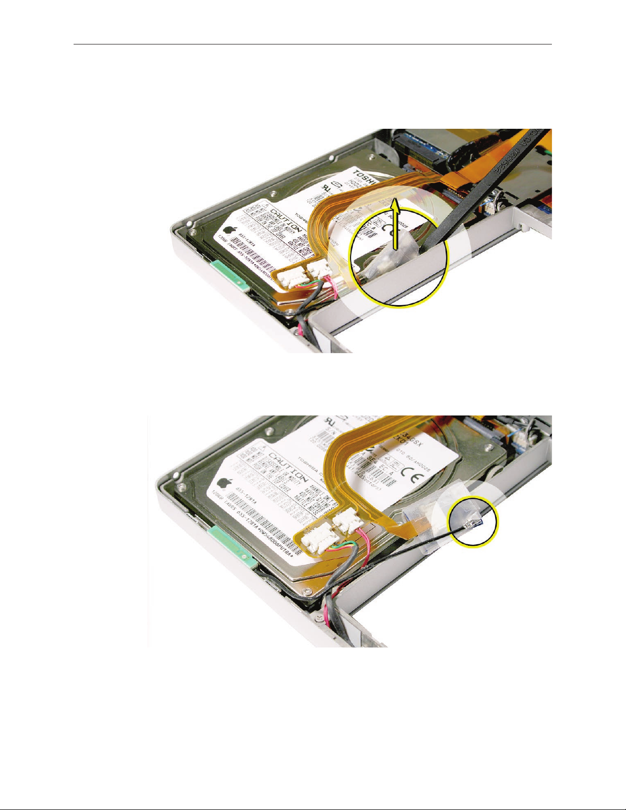
Lift the bluetooth card assembly to access the antenna connector. 1.
Disconnect the antenna cable connector. Pull straight up. If need, cut of the protective cover 2.
(as shown below).
MacBook Pro Take Apart — Bluetooth Card 60
Page 61
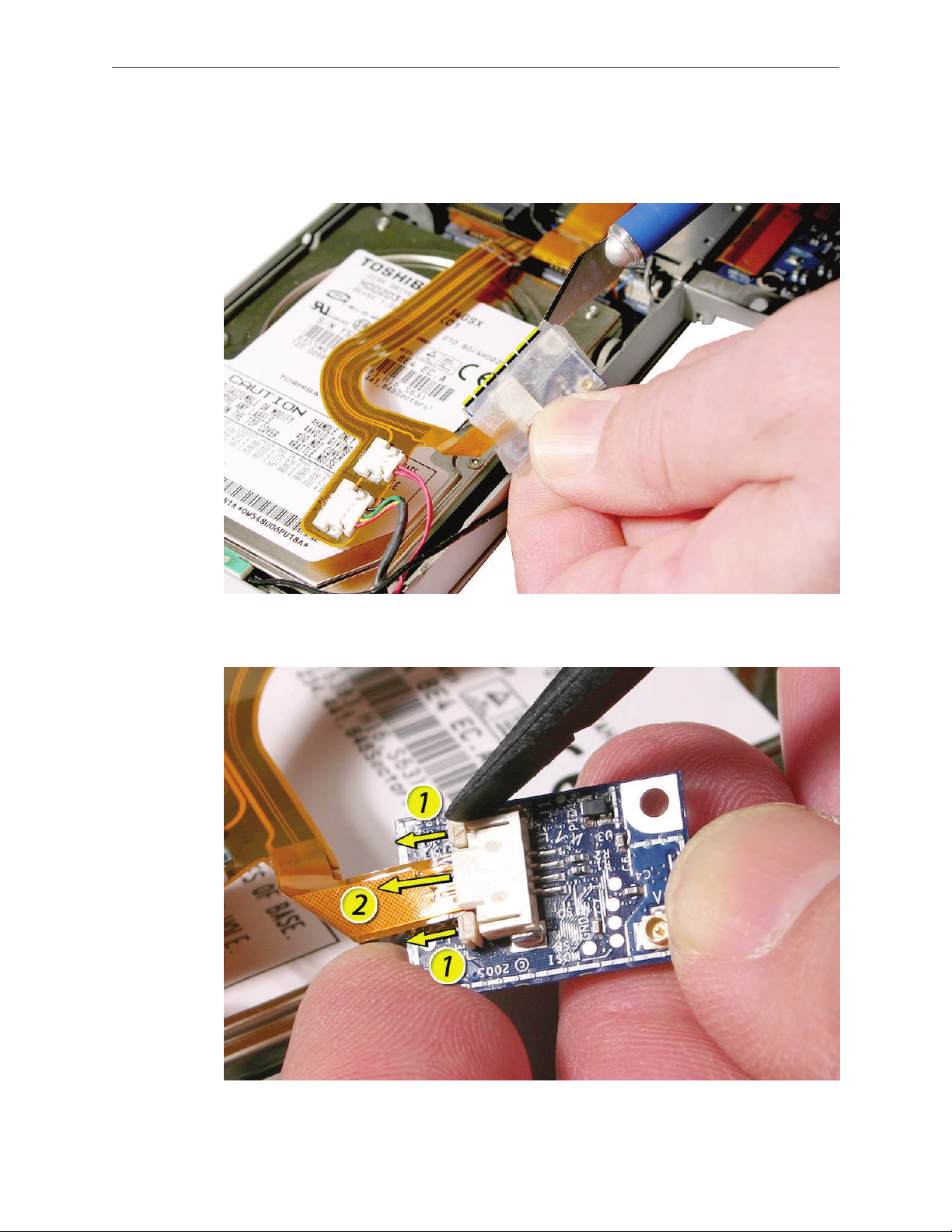
To access the ex cable connector, cut o the protective cover. 3.
Replacement Note: Reinstall the cover and secure with Kapton tape before reinstalling the
board
Disconnect the ex cable as shown. 4.
MacBook Pro Take Apart — Bluetooth Card 61
Page 62

Bluetooth Antenna
Tools
This procedure requires the following tools:
Black stick (nylon probe 922-5065) (or other non-conductive nylon or plastic at-blade tool•
Razor knife•
Kapton tape (922-1731 (0.5-inch x 12-yard roll))•
Preliminary Steps
Before you begin, remove the following:
Batter• y
Top Cas• e
Part Location
MacBook Pro Take Apart — Bluetooth Antenna 62
Page 63

Procedure
1. Lift the bluetooth card assembly to access the antenna connector.
2. Disconnect the antenna cable connector. Pull straight up. If needed, cut of the protective
cover.
MacBook Pro Take Apart — Bluetooth Antenna 63
Page 64
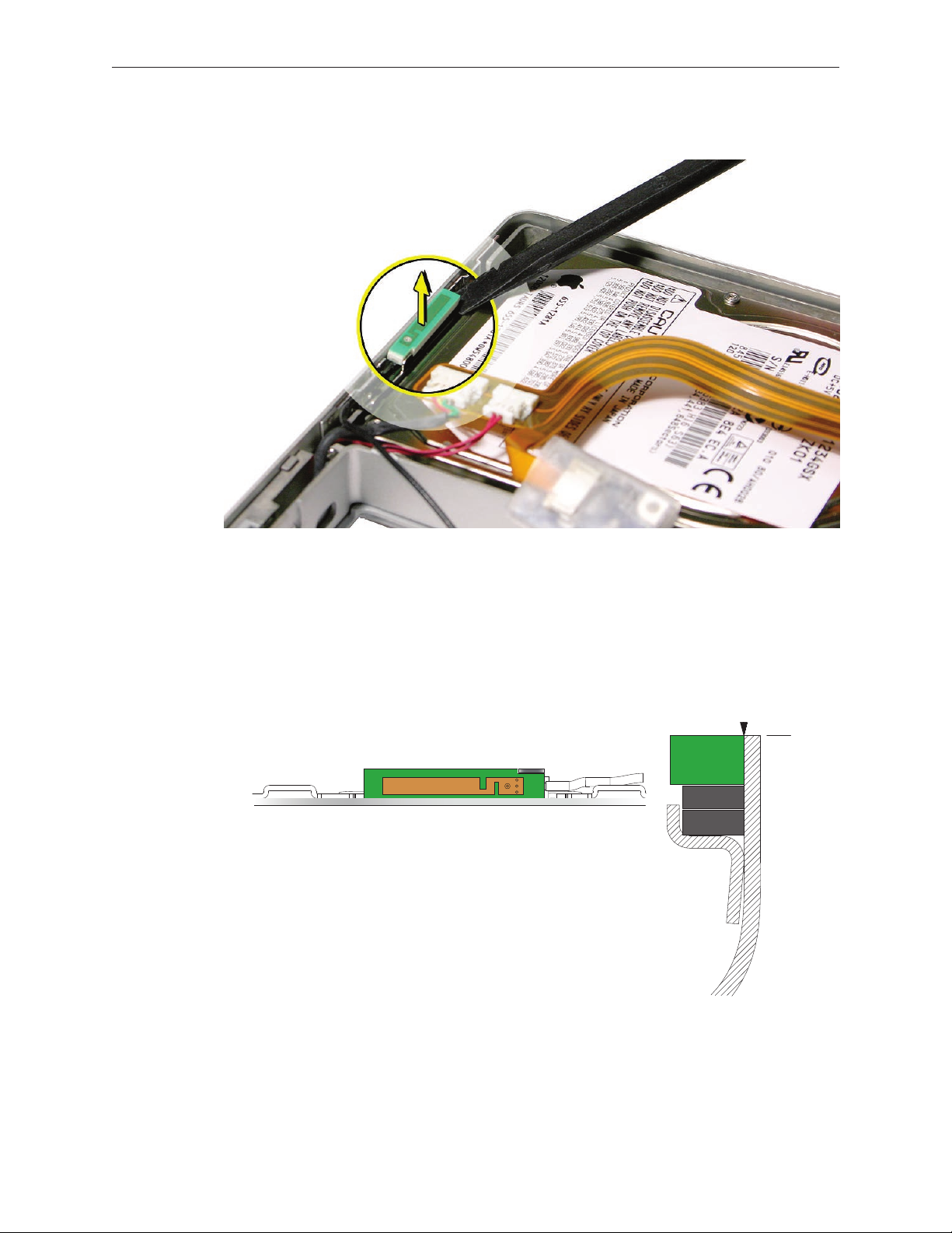
3. To remove the antenna, pry it up to release the adhesive.
A B
A
C
B
Replacement Procedure
Notes:
Important: • The position of the bluetooth antenna board (A) in the bottom case (B) is critical
to its function. Align the notch in the antenna board with the metal tab (C) then install the
board ush with the bottom case inside face and level with the bottom case top edge. .
On the bluetooth board, reinstall its protective cover and secure with Kapton tape before •
reinstalling.
MacBook Pro Take Apart — Bluetooth Antenna 64
Page 65
Infrared Board
Tools
This procedure requires the following tools:
Torx T6 screwdriver (magnetized)•
Black stick (nylon probe 922-5065) (or other non-conductive nylon or plastic at-blade tool•
Preliminary Steps
Before you begin, remove the following:
Batter• y
Top Cas• e
Part Location
MacBook Pro Take Apart — Infrared Board 65
Page 66

Procedure
Remove the screw and bracket1.
Disconnect the cable.2.
Lift out the infrared board. Lifting from both ends may be helpful. 1. Important: Lift on the
board only. Do NOT lift the infrared lens or sensor piece. It is secured to the main board with
two wires and will bend out of alignment.
MacBook Pro Take Apart — Infrared Board 66
Page 67

Note the cable routing and remove. 2.
Replacement Procedure
Route the cable.1.
To install, insert the board all the way into the channel, then push it forward until it stops 2.
and the infrared lens aligns with the window.
Important: Push on the board only. Do NOT push on the infrared lens or sensor piece. It is
secured to the main board with two wires and will bend out of alignment.
Connect the cable connector.3.
MacBook Pro Take Apart — Infrared Board 67
Page 68

Hard Drive
Tools
This procedure requires the following tools:
#0 Phillips screwdriver (magnetized)•
Torx T6 screwdriver (magnetized)•
Black stick (nylon probe 922-5065) (or other non-conductive nylon or plastic at-blade tool•
Kapton tape (922-1731 (0.5-inch x 12-yard roll))•
Preliminary Steps
Before you begin, remove the following:
Batter• y
Top Cas• e
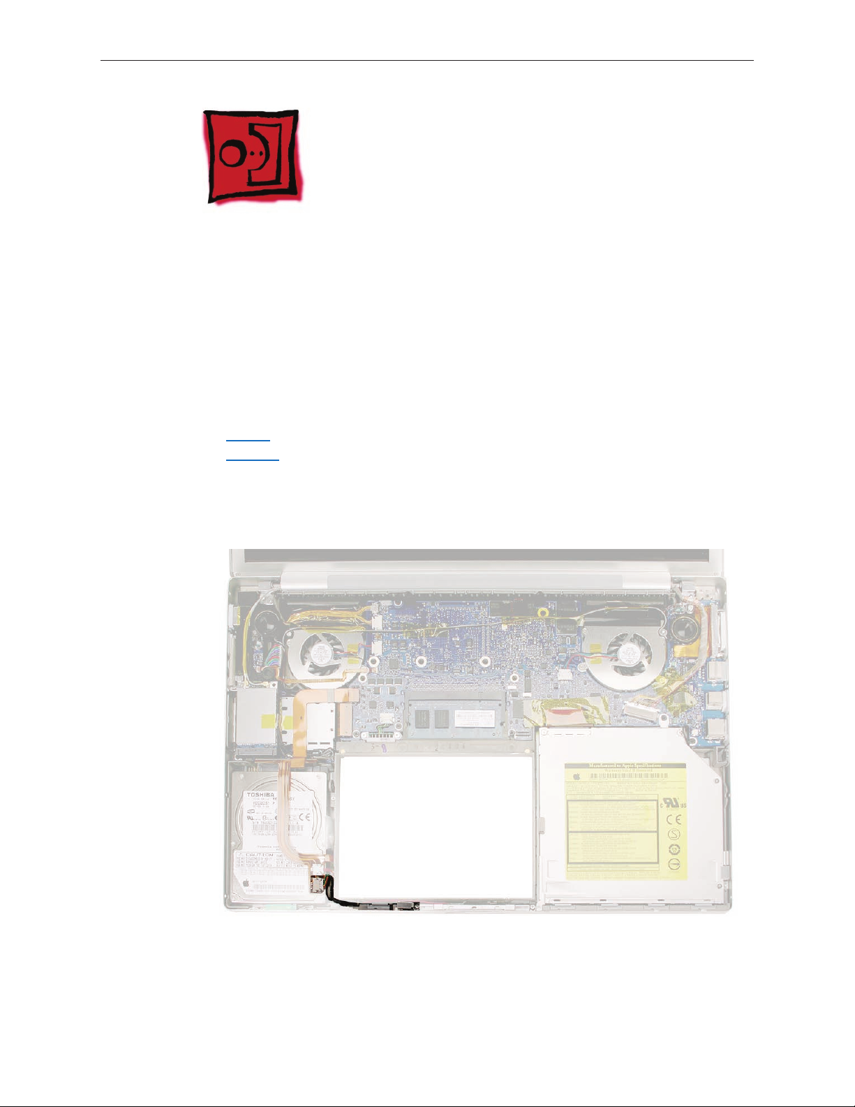
Part Location
MacBook Pro Take Apart — Hard Drive 68
Page 69
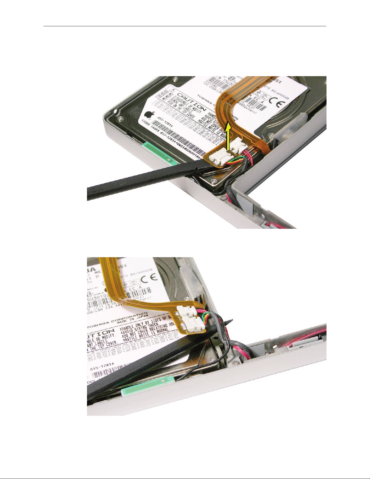
Procedure
Carefully pry up the ex cable from the hard drive. 1.
Lift up cabling to gain some clearance. 2.
MacBook Pro Take Apart — Hard Drive 69
Page 70

Remove the two screws from the drive holder. 3.
Lift the hard drive up slightly to allow it to move right. 4.
MacBook Pro Take Apart — Hard Drive 70
Page 71
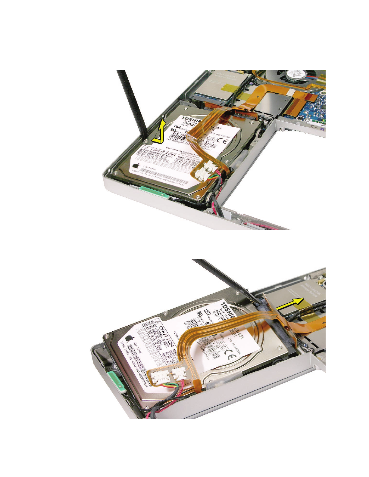
Push the hard drive away from the left side to clear the rubber grommets, then lift up just 5.
enough to access its ex connector.
6. Carefully push o the ex cable connector to disconnect it from the hard drive.
MacBook Pro Take Apart — Hard Drive 71
Page 72

Transfer the rubber grommets and screws. 7.
Replacement Procedure
Make sure that the rubber grommets t securely into the frame holes. 1.
MacBook Pro Take Apart — Hard Drive 72
Page 73

Use a black stick to lift the hard drive and guide the rubber grommets securely into the holes 2.
in the frame, while holding the bracket in place on the other grommets.
Use a black stick to guide the hard drive past the bluetooth card. 3.
MacBook Pro Take Apart — Hard Drive 73
Page 74
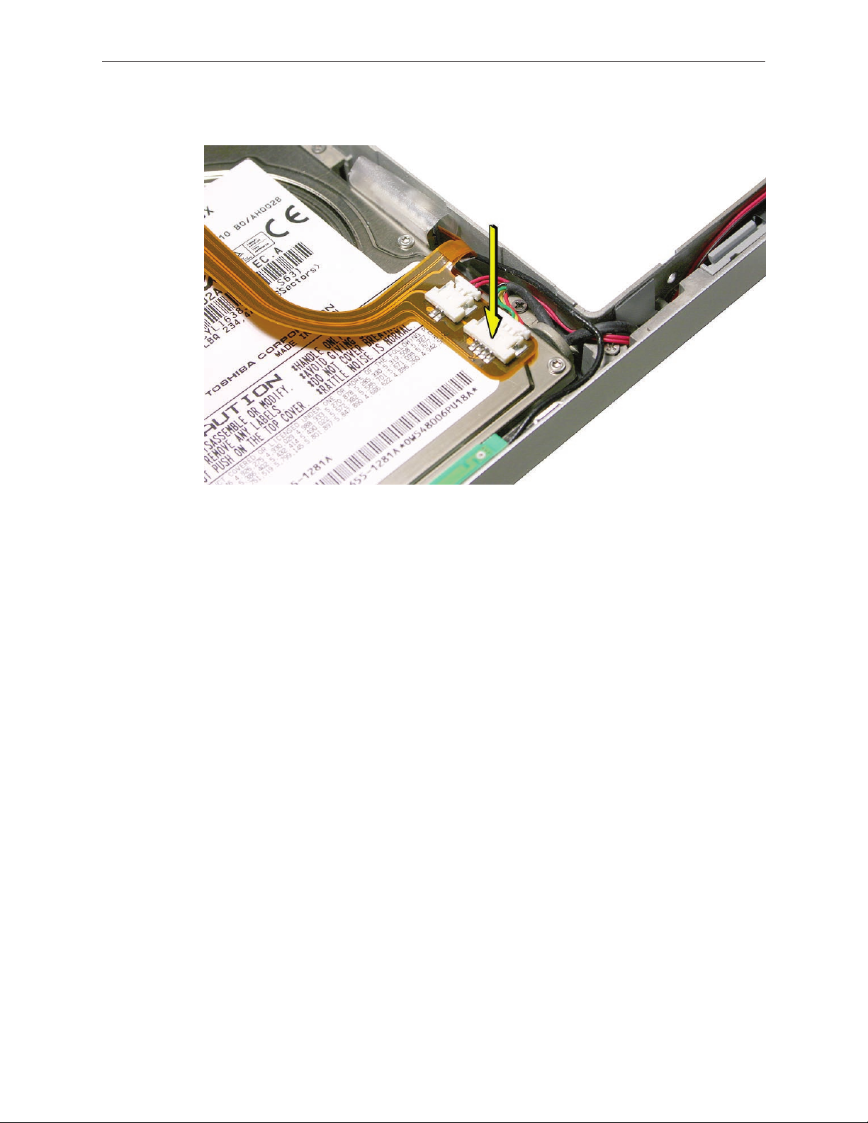
Press the ex cable to re-adhere it to the hard drive. 4.
MacBook Pro Take Apart — Hard Drive 74
Page 75

Optical Drive
Tools
This procedure requires the following tools:
#0 Phillips screwdriver (magnetized)•
Torx T6 screwdriver (magnetized)•
Black stick (nylon probe 922-5065) (or other non-conductive nylon or plastic at-blade tool•
Kapton tape•
Preliminary Steps
Before you begin, remove the following:
Batter• y
Top Cas• e
Part Location
MacBook Pro Take Apart — Optical Drive 75
Page 76

Procedure
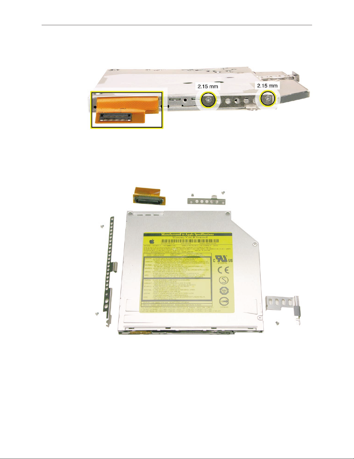
Carefully peel o any Kapton tape, then disconnect the ex connector.1.
2. Remove three screws and lift out the drive.
Transfer three brackets, including one EMI gasket, and ex cable to the replacement drive. 3.
MacBook Pro Take Apart — Optical Drive 76
Page 77
MacBook Pro Take Apart — Optical Drive 77
Page 78
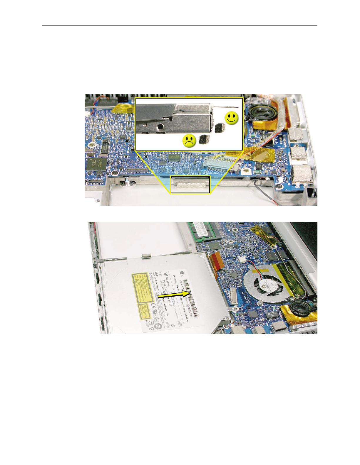
Replacement Procedure
Verify that the EMI gasket is installed on the bottom case in the back of the drive bay.1.
Important:2. The optical drive must be installed so that it does not sit on top of the gasket.
Insert the drive toward the logic board so that the gasket is pushed behind the drive.
Carefully reconnect the ex cable connector to the logic board. Make sure that it is fully 3.
seated and at.
Apply new Kapton tape to secure the connector in place.4.
MacBook Pro Take Apart — Optical Drive 78
Page 79
Backup Battery
Tools
This procedure requires the following tools:
#0 Phillips screwdriver (magnetized)•
Torx T6 screwdriver (magnetized)•
Needle-point metal probe•
Black stick (nylon probe 922-5065) (or other non-conductive nylon or plastic at-blade tool•
Preliminary Steps
Before you begin, remove the following:
Batter• y
Top Cas• e
Optical Driv• e
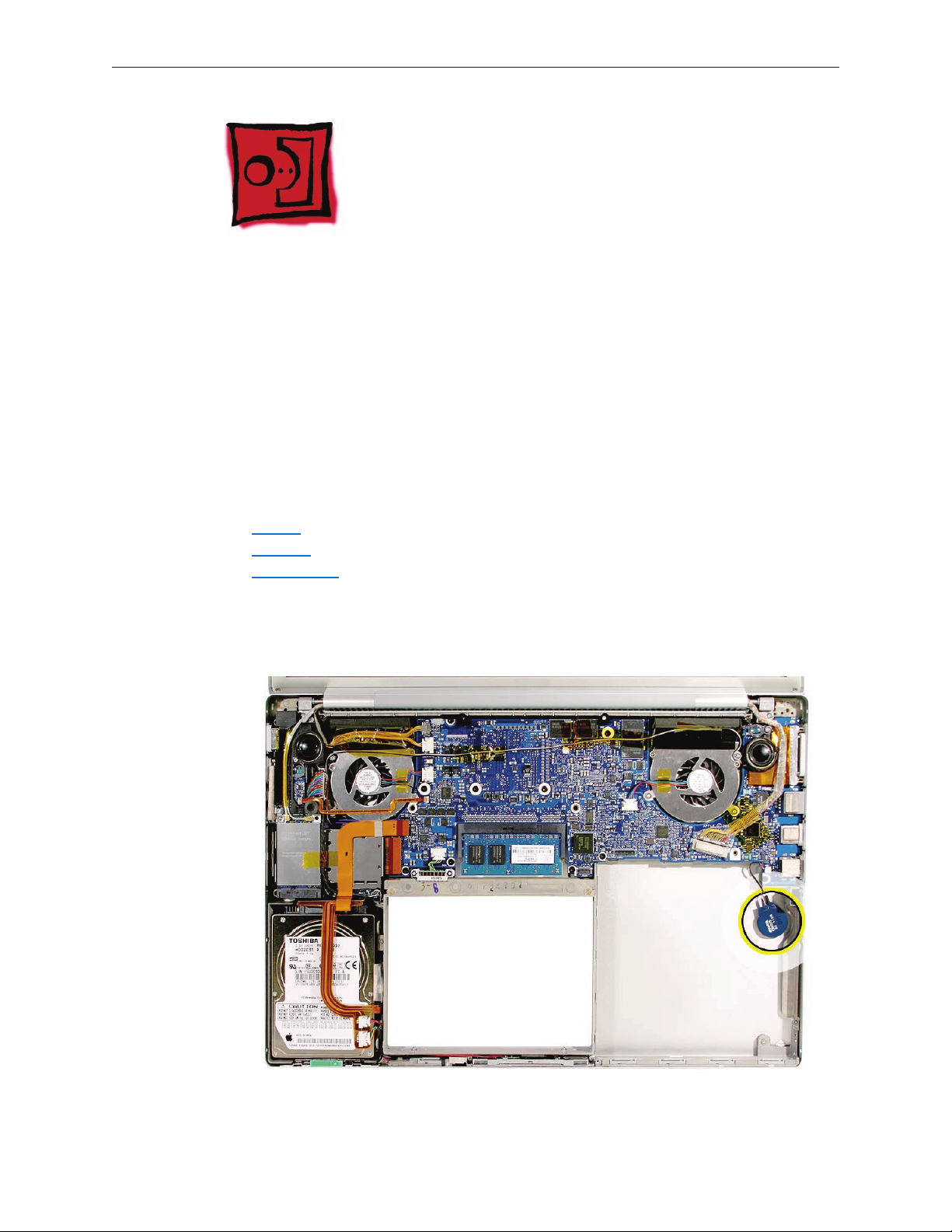
Part Location
MacBook Pro Take Apart — Backup Battery 79
Page 80

Procedure
Disconnect the cable from the logic board. 1.
Pry up the backup battery from the bottom case. 2.
Disconnect the cable connector. 3. Note: Using a metal needle-point probe may be helpful.
MacBook Pro Take Apart — Backup Battery 80
Page 81

To install, remove the adhesive protector and press the backup battery into place in the 4.
same location that it was removed.
Connect the cable to the logic board. 5.
Note: The connector is keyed. For reinstalling, note its orientation, below.
MacBook Pro Take Apart — Backup Battery 81
Page 82
Ambient Light Sensors
Tools
This procedure requires the following tools:
#0 Phillips screwdriver (magnetized)•
Torx T6 screwdriver (magnetized)•
Black stick (nylon probe 922-5065) (or other non-conductive nylon or plastic at-blade tool•
Preliminary Steps
Before you begin, remove the following:
Batter• y
Top Cas• e
Part Location
MacBook Pro Take Apart — Ambient Light Sensors 82
Page 83
Procedure
The right ambient light sensor is part of the logic board but has a removable dust cover. The left
sensor is on a circuit board mounted to the left speaker.
To remove the right sensor’s dust cover:
Remove the screw shown. 1.
The cover catches under the logic board. Slide the cover to the left to disengage. 2.
MacBook Pro Take Apart — Ambient Light Sensors 83
Page 84
To remove the left ambient light sensor board:
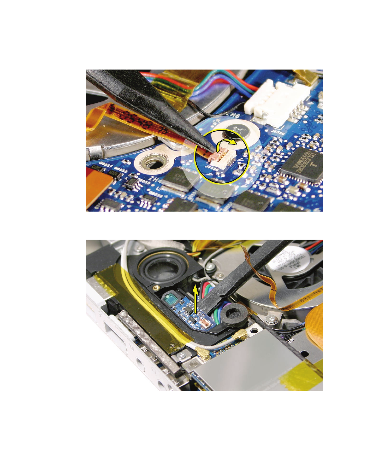
Remove the screw and dust cover.1.
Disconnect the ex connector on the sensor board (connector close-up shown below).2.
If replacing the ex cable, also disconnect it on the logic board (close-up shown below). 3.
Warning: The connectors are very delicate. Breaking the connector mechanism on the
logic board requires a replacement logic board!
4. Carefully lift the ex connector latch on the sensor board and slide the cable out.
MacBook Pro Take Apart — Ambient Light Sensors 84
Page 85
If removing the ex cable on the logic board, carefully lift the latch and remove the cable. 5.
Warning: Breaking this connector mechanism requires a replacement logic board!
Pry up the sensor board to release its adhesive and remove it from the speaker. 6.
MacBook Pro Take Apart — Ambient Light Sensors 85
Page 86

Fans
Tools
This procedure requires the following tools:
Torx T6 screwdriver (magnetized)•
Black stick (nylon probe 922-5065) (or other non-conductive nylon or plastic at-blade tool•
Razor knife•
Kapton tape (922-1731 (0.5-inch x 12-yard roll))•
Preliminary Steps
Before you begin, remove the following:
Batter• y
Top Cas• e
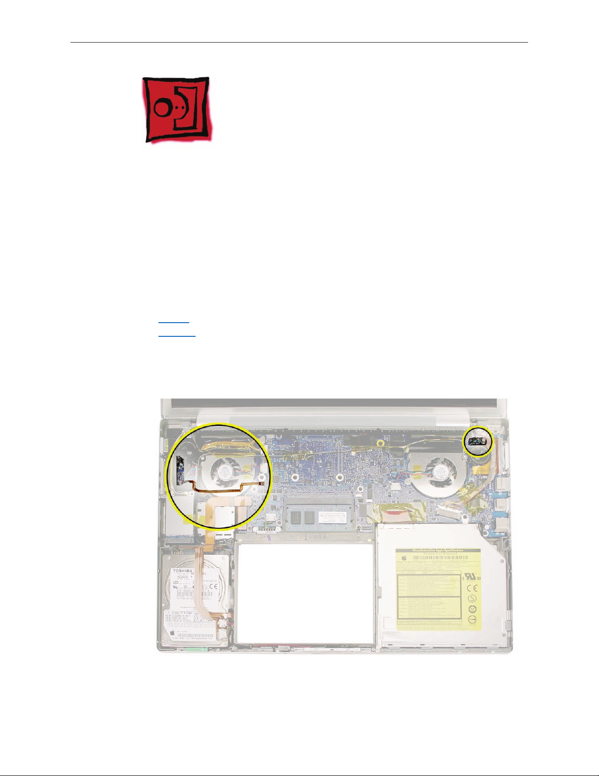
Part Location
MacBook Pro Take Apart — Fans 86
Page 87

Procedure
To remove the right fan:
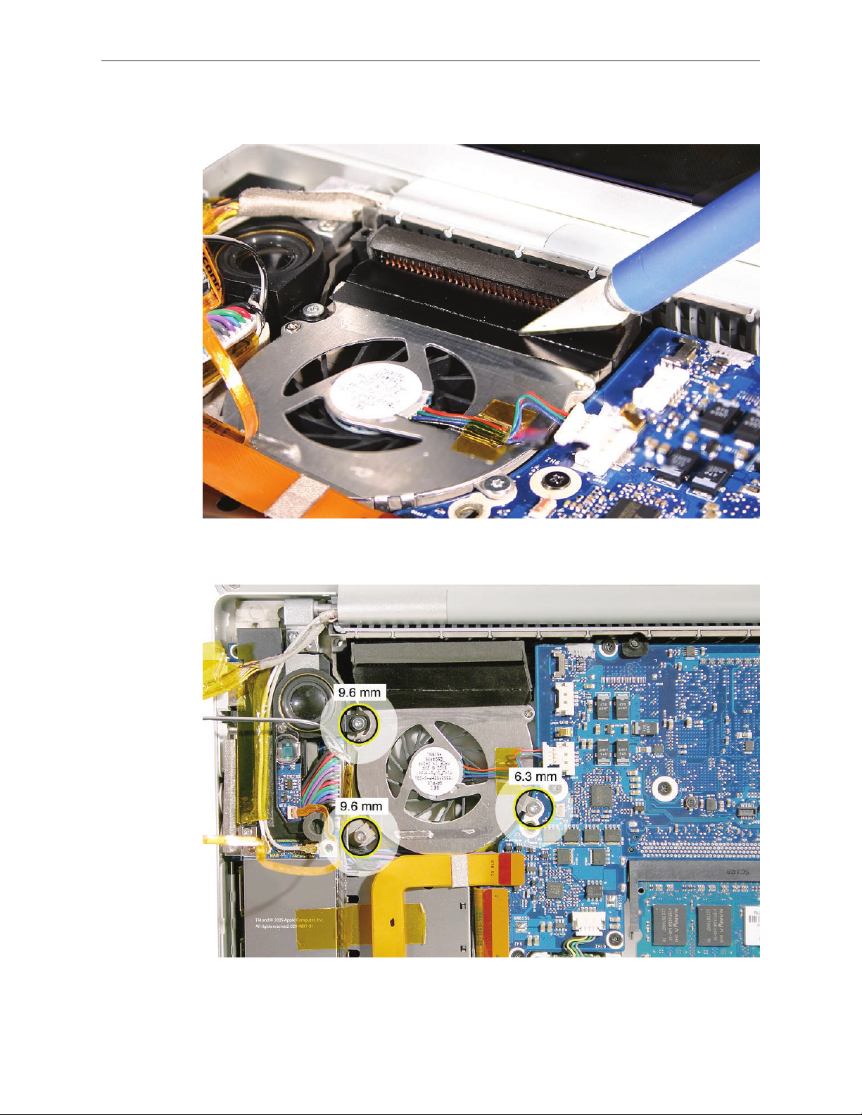
Peel up any Kapton tape and move the speaker cable safely out of the way, then use a razor 1.
knife to cut the length of the tape at the seam between the fan cover and the ns.
Disconnect the fan cable and remove three screws. Lift out the fan.2.
MacBook Pro Take Apart — Fans 87
Page 88

To remove the left fan:
Disconnect the ambient light sensor ex cable on the logic board (close-up shown below). 1.
Warning: The connector is very delicate. Breaking the connector mechanism requires a
replacement logic board!
MacBook Pro Take Apart — Fans 88
Page 89

Carefully peel the ex cable o the fan cover. 2.
Disconnect the cables shown, and move safely out of the way. 3.
MacBook Pro Take Apart — Fans 89
Page 90
Use a razor knife to cut the length of the tape at the seam between the fan cover and the ns4.
Remove the three screws. 5.
MacBook Pro Take Apart — Fans 90
Page 91

Slide the fan out from under the left speaker screw tab. 6.
MacBook Pro Take Apart — Fans 91
Page 92

Replacement Procedure
For both fans, after replacing, apply Kapton tape over the length of the cut tape, to seal. 1.
Secure the ambient light sensor ex cable to the left fan cover with Kapton tape, if needed.2.
V3. erify that the thermal sensor cable is not caught under the right fan.
MacBook Pro Take Apart — Fans 92
Page 93

Speakers
The right and left speakers are one assembly.
Tools
This procedure requires the following tools:
#0 Phillips screwdriver (magnetized)•
Torx T6 screwdriver (magnetized)•
Black stick (nylon probe 922-5065) (or other non-conductive nylon or plastic at-blade tool•
Kapton tape (922-1731 (0.5-inch x 12-yard roll))•
Preliminary Steps
Before you begin, remove the following:
Batter• y
Top Cas• e
AirPort Extreme Car• d (for left speaker)
Right Ambient Light Sensor Len• s (for right speaker)
Part Location
MacBook Pro Take Apart — Speakers 93
Page 94

Procedure
To remove the right speaker:
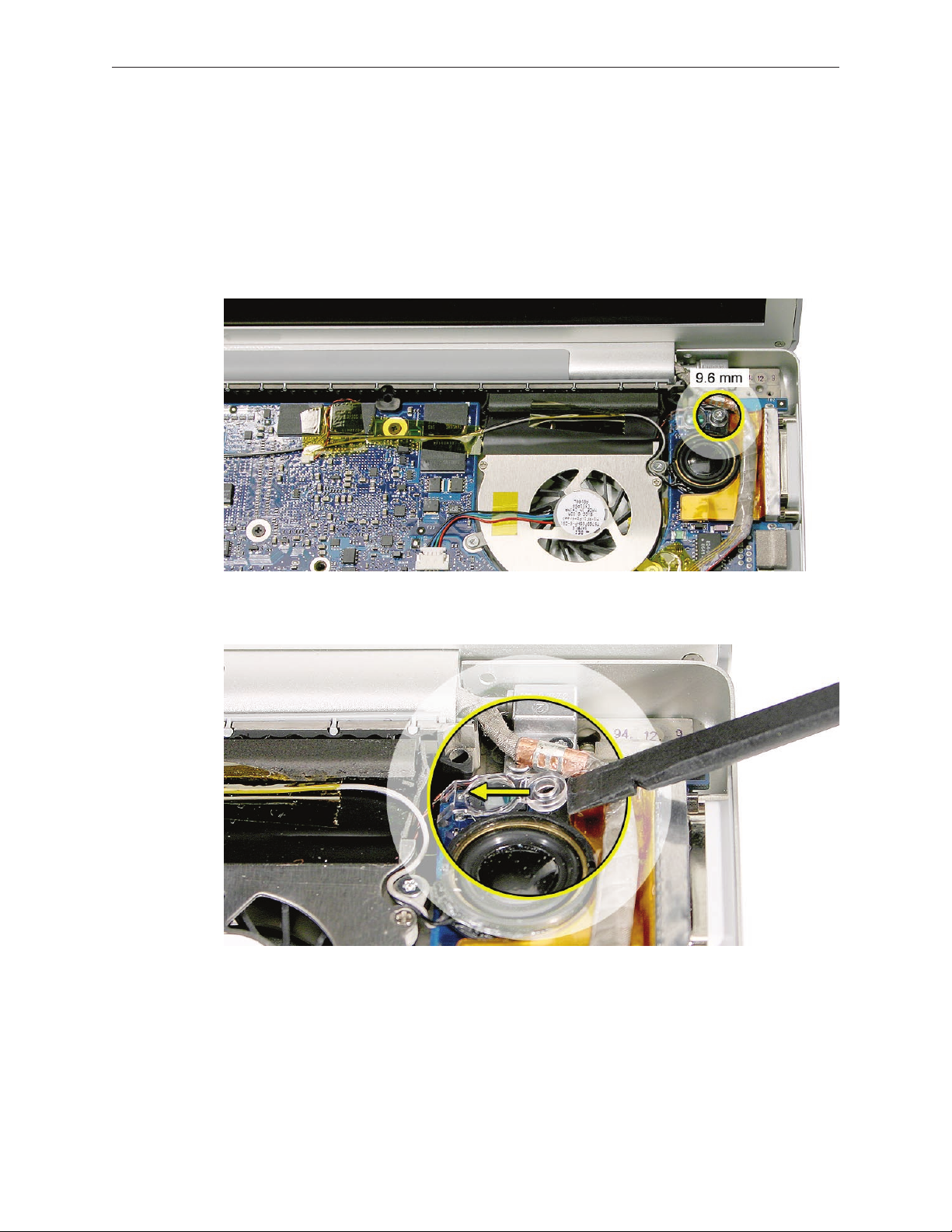
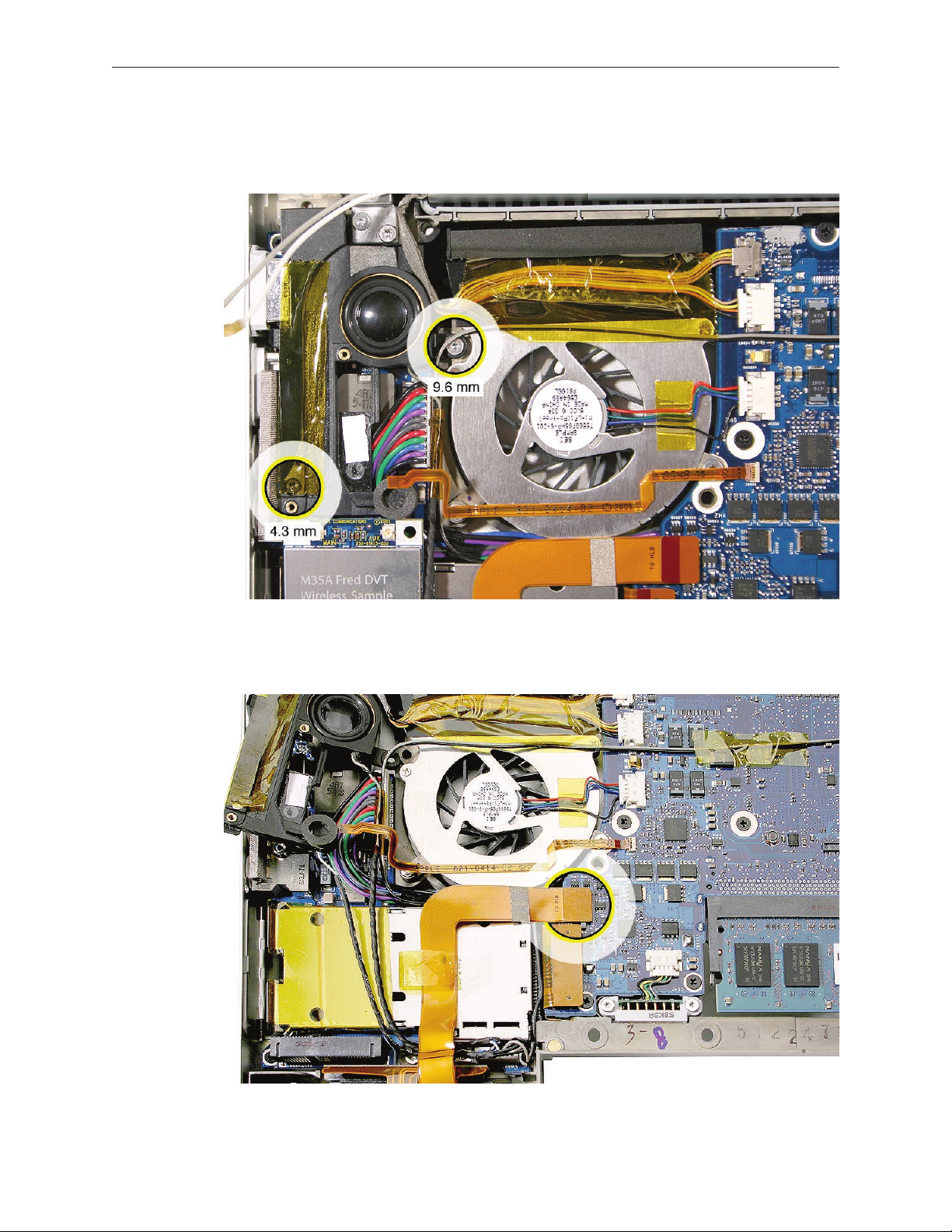
Remove the LVDS grounding strap screw to access the tape along the right side of the speaker. 1.
Pry up the tape next to the speaker to allow the speaker to rotate. 2.
MacBook Pro Take Apart — Speakers 94
Page 95
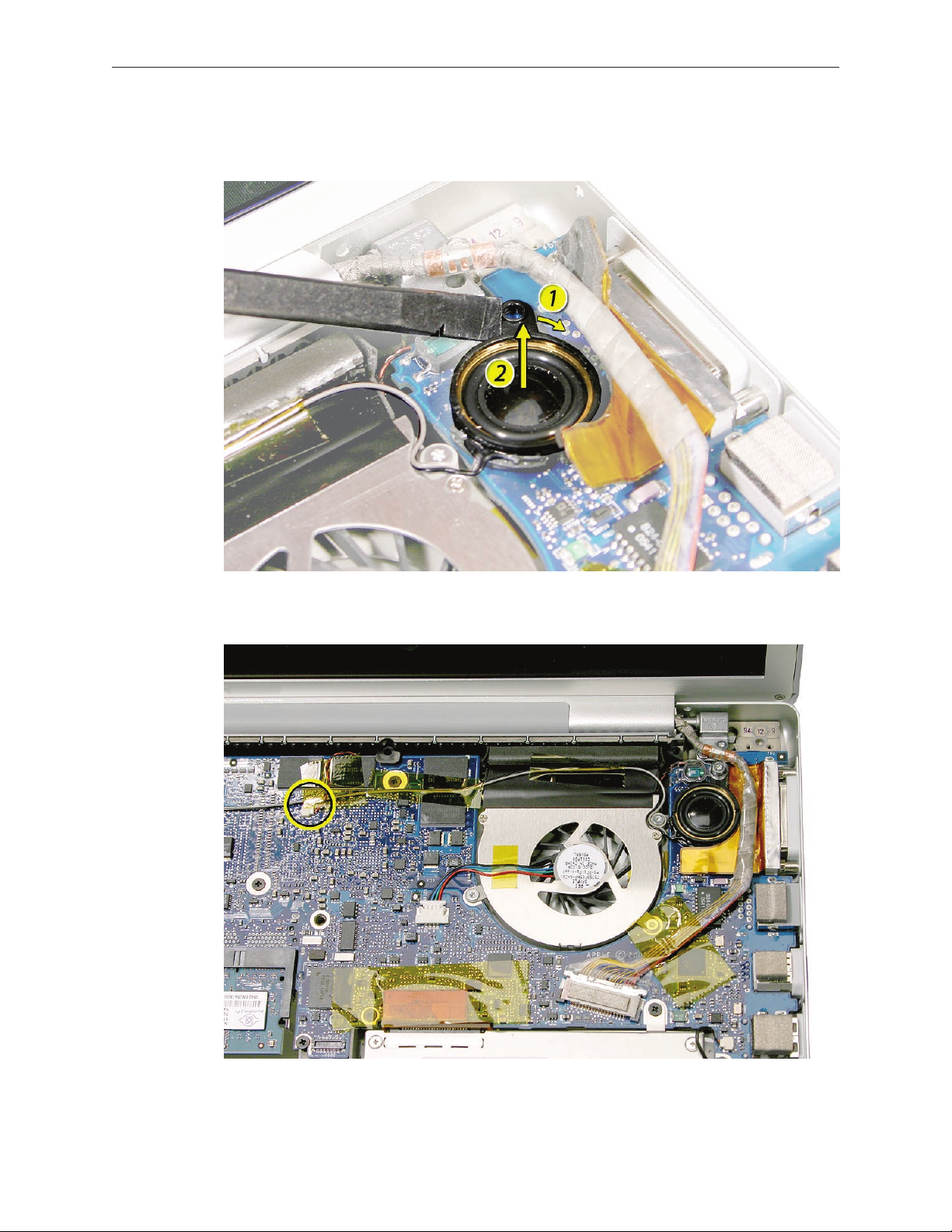
Push on the screw tab to rotate the speaker a short distance until it releases from the 3.
speaker chamber under the logic board. Lift out the speaker and move to the side.
Disconnect the thermal sensor connector, shown, if its wire crosses over the speaker wire. 4.
MacBook Pro Take Apart — Speakers 95
Page 96

Replacement Note: Check the circle gasket in the lower speaker chamber and re-seat if needed.
Replacement Note: Route the wires as shown.
MacBook Pro Take Apart — Speakers 96
Page 97
To remove the left speaker:
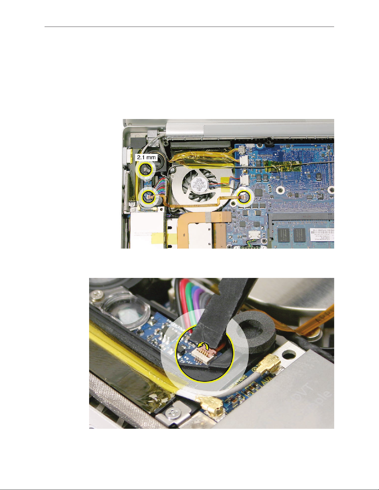
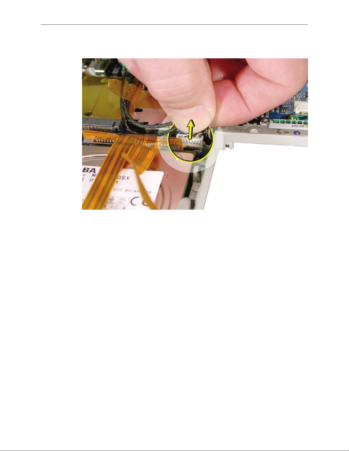
Remove two screws. 1.
Disconnect the connector shown and lift the ex cable from the ExpressCard cage to gain 2.
access to the speaker cables and connector.
MacBook Pro Take Apart — Speakers 97
Page 98
Note cable routing, then disconnect the speaker cable connector. 3.
MacBook Pro Take Apart — Speakers 98
Page 99

Logic Board
Tools
This procedure requires the following tools:
#0 Phillips screwdriver (magnetized)•
Torx T6 screwdriver (magnetized)•
Black stick (nylon probe 922-5065) (or other non-conductive nylon or plastic at-blade tool•
Needle-point metal probe•
Multi-compartment screw tray (such as a plastic ice cube tray)•
Kapton tape (922-1731 (0.5-inch x 12-yard roll))•
Thermal grease (922-7144)•
Gasket kit (076-1206)•
Alcohol pads•
Preliminary Steps
Before you begin, remove the following:
Batter• y
Memor• y
Top Cas• e
Right Speake• r
Fan• s
Optical Driv• e
MacBook Pro Take Apart — Logic Board 99
Page 100

Part Location
Procedure
Disconnect the cables shown.1. .
MacBook Pro Take Apart — Logic Board 100
 Loading...