

Page 1

User Manual English
APC Smart-UPS® RT
UXI/UXICH
SURT15000/20000 VA
230 Vac
Tower
Uninterruptible Power Supply
990-2484A 08/2007
Page 2

Page 3

Contents
Introduction. . . . . . . . . . . . . . . . . . . . . . . . . . . . . . . . . . . . . . . . . . . . . . . . . . . 1
About this UPS . . . . . . . . . . . . . . . . . . . . . . . . . . . . . . . . . . . . . . . . . 1
Unpack package contents . . . . . . . . . . . . . . . . . . . . . . . . . . . . . . . . . . 1
Specifications . . . . . . . . . . . . . . . . . . . . . . . . . . . . . . . . . . . . . . . . . . . . . . . . . 2
Installation. . . . . . . . . . . . . . . . . . . . . . . . . . . . . . . . . . . . . . . . . . . . . . . . . . . . 3
Install PowerView . . . . . . . . . . . . . . . . . . . . . . . . . . . . . . . . . . . . . . . .3
Connect PowerView . . . . . . . . . . . . . . . . . . . . . . . . . . . . . . . . . . . . . .4
Route ethernet cable and install top cover and bezels . . . . . . . . . . . . . . . .4
Accessories . . . . . . . . . . . . . . . . . . . . . . . . . . . . . . . . . . . . . . . . . . .6
Optional accessories . . . . . . . . . . . . . . . . . . . . . . . . . . . . . . . . . . . . . 6
Hardwire the UPS . . . . . . . . . . . . . . . . . . . . . . . . . . . . . . . . . . . . . . . . . . . . . . 6
Install input and output wiring trays in UPS rear panel . . . . . . . . . . . . . . . 7
Wiring Specifications . . . . . . . . . . . . . . . . . . . . . . . . . . . . . . . . . . . . .8
Input wiring options . . . . . . . . . . . . . . . . . . . . . . . . . . . . . . . . . . . . . .9
Output wiring options . . . . . . . . . . . . . . . . . . . . . . . . . . . . . . . . . . . . 12
Connect the External Batteries . . . . . . . . . . . . . . . . . . . . . . . . . . . . . . . . . . 13
Battery Safety . . . . . . . . . . . . . . . . . . . . . . . . . . . . . . . . . . . . . . . . . 13
APC battery solution . . . . . . . . . . . . . . . . . . . . . . . . . . . . . . . . . . . . .13
Third party battery solution . . . . . . . . . . . . . . . . . . . . . . . . . . . . . . . .14
Operation. . . . . . . . . . . . . . . . . . . . . . . . . . . . . . . . . . . . . . . . . . . . . . . . . . . . 15
PowerView Interface Display . . . . . . . . . . . . . . . . . . . . . . . . . . . . . . . . . . . . 15
Navigating menu screens . . . . . . . . . . . . . . . . . . . . . . . . . . . . . . . . . 16
Start-Up . . . . . . . . . . . . . . . . . . . . . . . . . . . . . . . . . . . . . . . . . . . . . . . . . . . . . 20
Connect load to UPS . . . . . . . . . . . . . . . . . . . . . . . . . . . . . . . . . . . . . 20
Connect power to UPS and load . . . . . . . . . . . . . . . . . . . . . . . . . . . . . 20
Communication Ports . . . . . . . . . . . . . . . . . . . . . . . . . . . . . . . . . . . .20
Emergency Power Off (EPO) . . . . . . . . . . . . . . . . . . . . . . . . . . . . . . . . 21
Troubleshooting Display Messages . . . . . . . . . . . . . . . . . . . . . . . . . . . . . . 22
Smart-UPS RT 15000/20000 VA 230 Vac UXI/UXICH Tower User Manual i
Page 4

Service and Transport . . . . . . . . . . . . . . . . . . . . . . . . . . . . . . . . . . . . . . . . . 26
Two-Year Warranty. . . . . . . . . . . . . . . . . . . . . . . . . . . . . . . . . . . . . . . . . . . . 27
Contact Information . . . . . . . . . . . . . . . . . . . . . . . . . . . . . . . . . . . . . . . . . . . 28
Regulatory Agency Approvals . . . . . . . . . . . . . . . . . . . . . . . . . . . . . . . . . . 28
ii Smart-UPS RT 15000/20000 VA 230 Vac UXI/UXICH Tower User Manual
Page 5

Introduction
About this UPS
The American Power Conversion (APC®) Smart-UPS® RT is a high performance uninterruptible power
supply (UPS) that provides protection for electronic equipment from utility power blackouts, brownouts, sags
and surges. The UPS protects electronic equipment from small utility fluctuations and large disturbances by
providing continuous on-line double converted power. The UPS provides battery backup until utility power
returns to safe levels or the batteries are fully discharged.
Unpack package contents
Read the Safety Guide before installing the UPS.
Inspect the UPS upon receipt. Notify the carrier and dealer if there is damage.
The packaging is recyclable; save it for reuse or dispose of it properly.
Check the package contents:
•UPS
• Front bezel (2)
• Top cover and four screws
• Input wiring tray
• Output wiring tray
• PowerView display module
• Battery cable assemblies
• DB9 serial cable
• Ground wire
NOTE: The model and serial numbers are located on a small, rear panel label. For some models, an
additional label is located on the chassis under the front bezel.
• Literature kit containing:
– Product documentation
– Smart-UPS® RT User Manuals CD
– Network Management Card Utility CD
– Network Management Card documentation
– Safety information
– Warranty information
Smart-UPS RT 15000/20000 VA 230 Vac UXI/UXICH Tower User Manual 1
Page 6
Specifications
Environmental Specifications
Temperature
Operating
Storage
32° to 104° F (0° to 40° C)
5
° to 113° F (-15° to 45° C) charge the UPS battery every
six months
86
° to 158° F (30° to 70° C) charge the UPS battery every
three months
Maximum
Elevation
Operating
Storage
Humidity
10,000 ft (3,000 m)
50,000 ft (15,240 m)
0 to 95% relative humidity, non-condensing
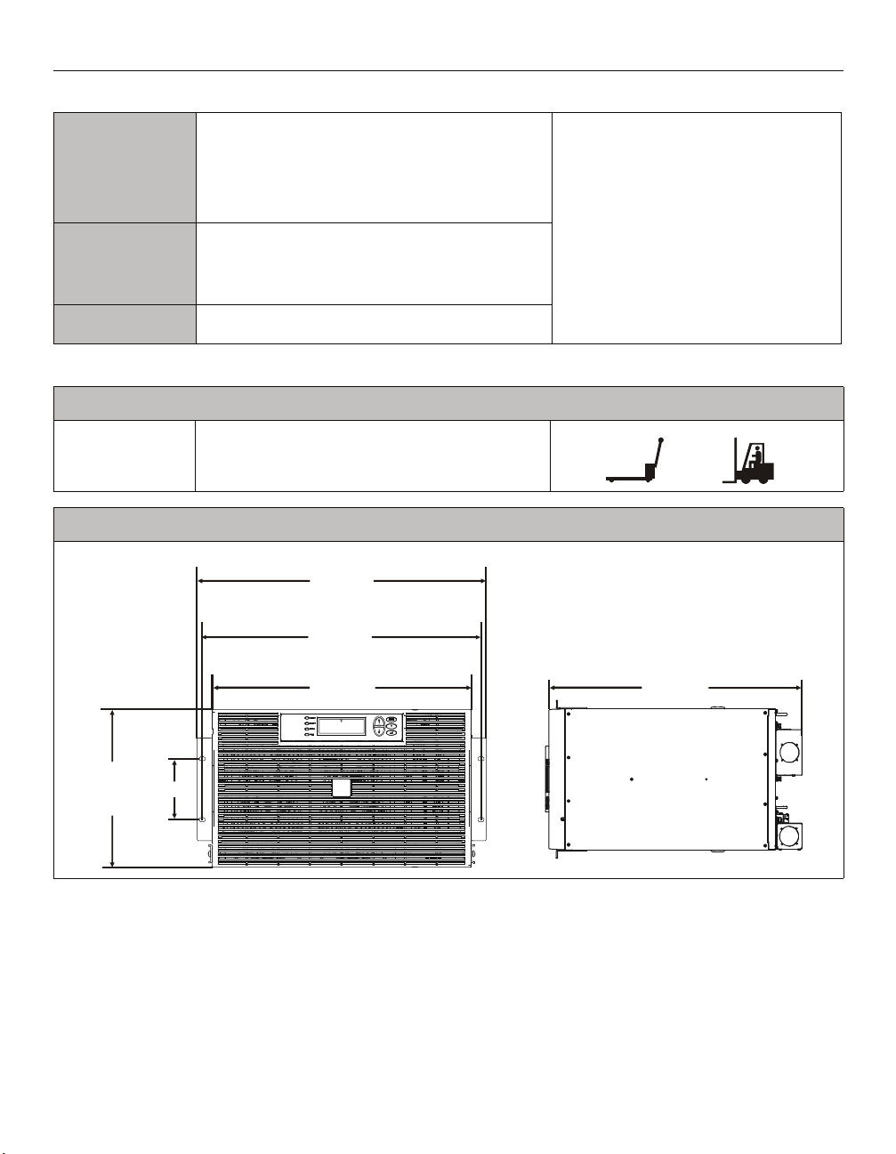
Physical Specifications
Wei ght (unpacked)
UPS
Dimensions
145 lbs (66 kg)
This unit is intended for indoor use only.
Select a location sturdy enough to handle
the weight.
Do not operate the UPS where there is
excessive dust or the temperature or
humidity are outside the specified limits.
This unit has front to rear airflow. Allow
adequate space for proper ventilation.
Environmental factors impact battery life.
High temperatures, poor utility power, and
frequent, short duration discharges will
shorten battery life.
482 mm
19 in
465 mm
18.3 in
432 mm
17 in
102 mm
10.4 in
4 in
263 mm
2 Smart-UPS RT 15000/20000 VA 230 Vac UXI/UXICH Tower User Manual
773 mm
30.4 in
Page 7
Installation
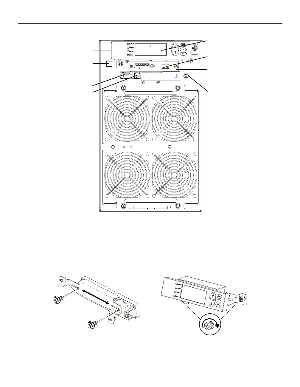
Tower front panel
PowerView
RJ45 Connector (pass through
to Rear Panel RJ45 Connector
Serial Port
PowerView Cable Connector
Interface Display
Ethernet Port 10/100 Base-T
SmartSlot with Network
Management Card
Cold Start/EPO reset
Install PowerView
Prior to attaching the PowerView to the UPS:
1. Loosen the two bracket screws on the back of the PowerView module.
a. Slide the bracket to the position that will accommodate the screw holes on the UPS.
b. Tighten the screws on the bracket.
2. Secure the PowerView to the UPS using the two thumb screws attached to the PowerView.
Smart-UPS RT 15000/20000 VA 230 Vac UXI/UXICH Tower User Manual 3
Page 8
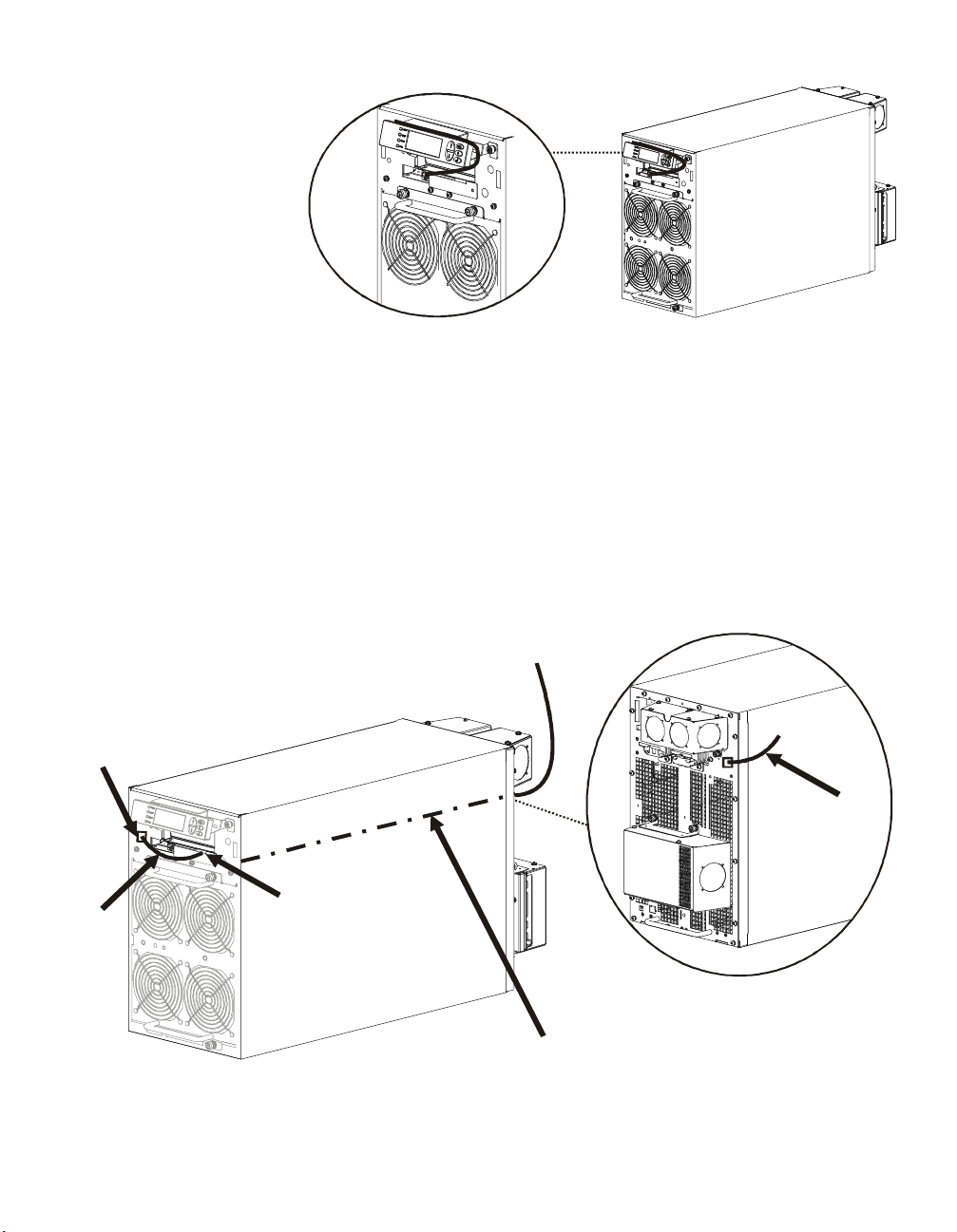
Connect PowerView
Connect the PowerView cable
to the PowerView connector on
UPS.
Route ethernet cable and install top cover and bezels
There are three ways to access the ethernet port on this unit:
1. Rear panel access utilizing ethernet jumper cable on front panel
2. Front panel access routing ethernet cable under top cover
3. Front panel access routing ethernet cable through bezel notch
Rear panel access utilizing ethernet jumper cable on front panel
Locate the RJ45 connector and the ethernet port on the front panel of the UPS. Connect the ethernet jumper
cable (included), to the RJ45 connector and the ethernet port.
Connect a network cable (not included), to the RJ45 connector on the rear panel of the UPS.
Ethernet Cable connected to Rear Panel
RJ45 Connector
RJ45
Connector
Ethernet Cable
Ethernet Port
Ethernet
Jumper
Cable
Internal Pass Through Ethernet Cable Connecting
Front and Rear Panel RJ45 Connectors
4 Smart-UPS RT 15000/20000 VA 230 Vac UXI/UXICH Tower User Manual
Page 9
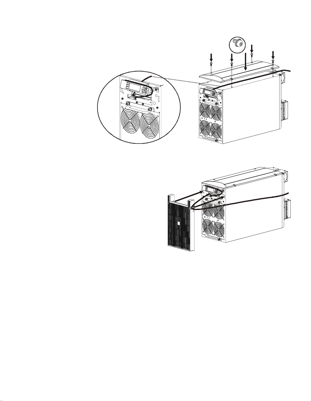
Front panel access routing ethernet cable under top cover
An ethernet cable can be routed behind the PowerView module, and over
the top of the UPS prior to installing the top cover.
Install the top cover.
Front panel access routing ethernet cable through bezel notch
An ethernet cable can be routed from the UPS through one of notches in the bezel
prior to installing the bezel.
Install the bezel.
4x
Smart-UPS RT 15000/20000 VA 230 Vac UXI/UXICH Tower User Manual 5
Page 10
Accessories
Install accessories prior to connecting power to the UPS.
• Refer to the APC Web site, www.apc.com for available accessories.
• User documentation for the Network Management Card installed on this UPS is available on the
Utility CD included with this unit.
Optional accessories
• Maintenance bypass
• Equipment cart
Hardwire the UPS
Wiring must be performed by a qualified electrician. Adhere to all local and national electrical codes.
1. For input wiring only, install a utility circuit breaker in accordance with local electrical codes.
2. Switch the utility circuit breaker OFF.
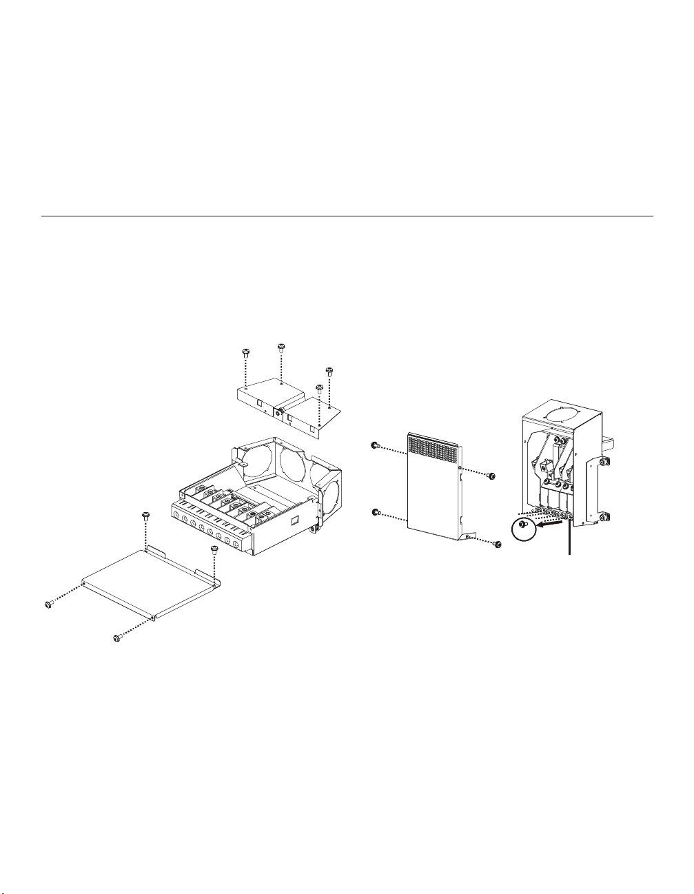
3. Remove the appropriate circular knockouts from the input and output wiring trays.
4. Remove the screws that secure the covers and take the covers off of the trays.
5. Remove the five screws that secure the strain relief bar.
Input wiring tray
Output wiring tray
5x
Strain relief bar
6. Remove the appropriate jumpers for input power source compatibility and output wiring options, (refer
to the Wiring sections in this manual).
7. Run wires through the knockout holes to the terminal blocks. Wire the ground terminal first, (refer to
tables and graphics in the Wiring sections this manual).
8. Use strain-relief (not supplied), on the hardwired input and output power cables.
9. Replace the wiring tray covers. Failure to do so may result in personal injury or equipment
damage.
10. Install the wiring trays, (refer to graphics below).
6 Smart-UPS RT 15000/20000 VA 230 Vac UXI/UXICH Tower User Manual
Page 11

Install input and output wiring trays in UPS rear panel
Input Wiring
Tray
Ground
RJ45 Connector (install front
panel ethernet jumper cable)
External Battery Pack
Connectors
Output Wiring
Tray
GroundEPO PortCold Start/
EPO reset
Input Wiring Tray
Output Wiring Tray
Smart-UPS RT 15000/20000 VA 230 Vac UXI/UXICH Tower User Manual 7
Page 12

Wiring Specifications
Adhere to national and local electrical codes when wiring.
Input Connections Output Connections
Main Input
Single-Phase: Wire to L1, N, and
Three-Phase: Wire to L1, L2, L3, N, and
Bypass Input (optional)
Single-Phase: Wire to B1, N, and
Three-Phase: Wire to B1, B2, B3, N, and
System Wiring Number
SURT15000UXI/
UXICH
Input 1 220/230/
of Phases
Input 3 380/400/
Output 1 220/230/
Output 3 380/400/
SURT20000XI/
UXICH
Input 1 220/230/
Input 3 380/400/
Output 1 220/230/
Output 3 380/400/
Hardwire
Single-Phase: Wire to L1, N, and
Three-Phase: Wire to L1, L2, L3, N, and
Single-phase PDU
XL battery pack PDU to UPS: Wire L1, N,
Vo lt ag e Current
Full Load
(maximum)
240 Vac
415 Vac
28 A / phase 35 A / 3-pole 6 mm
240 Vac
415 Vac
22 A / phase not required 6 mm
240 Vac
35 A / phase 50 A / 3-pole 10 mm
415 Vac
240 Vac
415 Vac
29 A / phase not required 10 mm
External Input
Circuit Breaker
Wire Size
(typical)*
(typical)
83 A 100 A / 1-pole 25/35 mm
(2/1 AWG)
(8 AWG)
65 A not required 25 mm
(2 AWG)
(8 AWG)
105 A 125 A / 1-pole 35/50 mm
(1/0 AWG)
(6 AWG)
87 A not required 35 mm
(1 AWG)
(6 AWG)
2
2
2
2
2
2
2
2
* Terminal screw tightening torque: 40 lbf-in (4.5 N-m)
The acceptable input frequency range is 40 to 70 Hz.
The output frequency is user selectable. Refer to the PowerView display menu screens for available options.
8 Smart-UPS RT 15000/20000 VA 230 Vac UXI/UXICH Tower User Manual
Page 13

Input wiring options
Input wiring overview: Refer to the diagrams on the following pages for input wiring options.
Main Input Power Single and Three Phase
Main Phase 1
Bypass Input Power Single and Three Phase
Bypass Phase 1
Main Phase 2
Main Phase 3
Neutral
Ground
Bypass Phase 2
Bypass Phase 3
L3NEUGND
MSJ
B3
B2B1L1L2
BSJ
Labeled jumpers must be
installed in the appropriate
SJ1
SJ2
locations.
SJ3
I
Input/Output Jumper Configurations
Power I/O
Configuration
Input:Output
1:1** No
1:1 Yes
3:1 No
3:1 Yes
3:3 No
3:3 Yes
Separate
Bypass Feed
Input
Jumpers
SJ1 SJ2 SJ3 MSJ BSJ OSJ
**
Output
Jumpers
* Optional
** Factory Default
Smart-UPS RT 15000/20000 VA 230 Vac UXI/UXICH Tower User Manual 9
Page 14
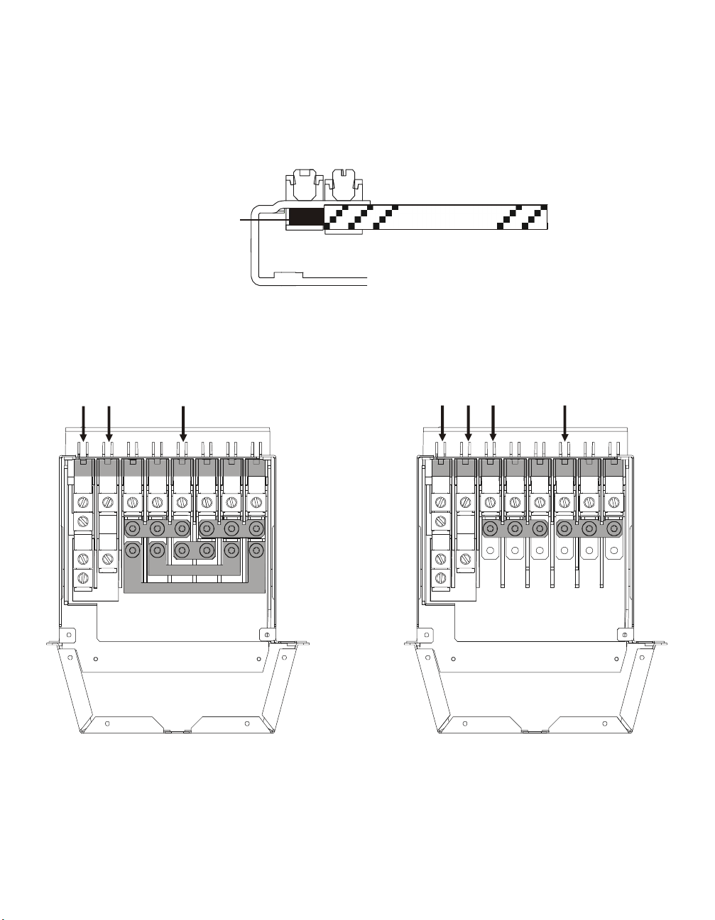
Ensure ground wire conductor and insulator are securely fastened. To connect the ground wire:
1. Strip the cable of insulation, exposing the wire. Secure the exposed wire with lug “A”.
2. Secure the insulated portion of the cable with lug “B”.
Stripped wire
Input wiring option 1 Factory Default
Single phase input, single phase output,
single feed
L3NEUGND
MSJ
SJ1
B2B1L1L2
SJ2
B3
BSJ
SJ3
Lug A
Lug B
Insulated wire
Input wiring option 2
Single phase input, single phase output,
dual feed
B3B2B1L1L2L3NEUGND
MSJ
BSJ
10 Smart-UPS RT 15000/20000 VA 230 Vac UXI/UXICH Tower User Manual
Page 15

Input wiring option 3
Three phase input, single phase output,
single feed
Input wiring option 4
Three phase input, single phase output,
dual feed
L3NEUGND
SJ1
B3
B2B1L1L2
BSJ
Input wiring option 5
Three phase input, three phase output,
single feed
L3NEUGND
B3
B2B1L1L2
BSJ
Input wiring option 6
Three phase input, three phase output, dual
feed
L3NEUGND
SJ1
Smart-UPS RT 15000/20000 VA 230 Vac UXI/UXICH Tower User Manual 11
B2B1L1L2
SJ2
B3
SJ3
L3NEUGND
B3
B2B1L1L2
Page 16

Output wiring options
Output wiring overview. Refer to the diagrams on the following pages for output wiring options.
Output Phase 3
Neutral
Ground
N
PDU Terminals
Output hardwire option 1
Single phase hardwire output connection
L3 L2 L1
OSJ
Output hardwire option 2
External battery pack PDU not connected
Output Phase 2
Output Phase 1
Factory Default Configuration
Output Shorting Jumper (OSJ)
for single phase output
Labeled jumpers and connectors
must be installed in the
appropriate locations.
N
12 Smart-UPS RT 15000/20000 VA 230 Vac UXI/UXICH Tower User Manual
L3
L2 L1
OSJ
Ensure the OSJ is secured
to the output wiring tray
using the five screws
provided.
N
L3
L2 L1
Page 17

Connect the External Batteries
Battery Safety
Read and adhere to the following warnings when installing or servicing the external batteries.
Failure to observe these warnings may result in serious injury, death, or damage to the equipment.
WARNINGS
• Do not attempt to install or service external batteries alone. A
qualified electrician should perform the installation and
servicing of external batteries.
• Disconnect charging source(s) BEFORE connecting or
disconnecting battery terminals.
• External batteries may retain lethal voltages after power has been
disconnected and all switches are off.
• Use extreme caution when making terminal connections. Do not
allow cables to touch anything except the intended terminal.
PRACTICES Always wear:
Always Use:
Remove:
PRECAUTIONS • To avoid static build-up, service personnel should establish a grounding
• Goggles or face shields
• Acid-resistant, insulated gloves
• Protective aprons
• Insulated tools
• Rubber mats to cover batteries during servicing
• Rubber mats or rubber stands on the floor
• Adequate lifting devices
• Watches, rings, and other metal objects from your body
contact prior working on batteries.
• Do not lay tools or metal parts on top of batteries.
• Lead-acid batteries contain hazardous, toxic materials.
– Do not open, alter or mutilate batteries. Internal materials may
be harmful to the skin and eyes.
– Do not dispose of batteries in a fire. There is danger of
explosion.
• Handle, transport and recycle batteries in accordance with local
codes and regulations.
APC battery solution
Refer to the APC Web site www.apc.com, or contact an APC dealer for information regarding APC external
battery pack(s).
Smart-UPS RT 15000/20000 VA 230 Vac UXI/UXICH Tower User Manual 13
Page 18

Third party battery solution
Batteries must be Sealed Lead-Acid type. Use 50 A, 250 Vdc fuses with an Interrupt rating of
>
20,000 A.
Ensure that the external batteries are wired prior to connecting the batteries to the UPS.
Two separate, isolated 192 V battery systems are required when using a third party battery solution. One cable
assembly must be wired to each 192 V battery system. Two cable assemblies are included with the UPS, one for
each 192 V battery system.
Each battery system must have identical Amp-hrs.
Connect the ground and wire the battery system
1. Connect the ground wires (supplied), to each battery enclosure ground and the ground screw on the back
of the UPS.
2. Cut off one of the connectors on each cable assembly exposing the positive and negative wires in each
cable.
3. Connect the positive and negative wires to the positive and negative terminals on each external battery
system. Ensure that the proper polarities are connected.
4. Plug the cable connectors into the battery connector receptacles on the back of the UPS.
5. Enter the external battery capacity through the PowerView menu.
a. This setting determines battery runtime and battery charge rate.
b. The number entered in the menu screen Ext Bat Cap, must equal the number of Amp-hrs in one of the
identical battery systems.
Fuse
Battery System
192 V 192 V
grnd
Battery System
192 V 192 V
grnd
14 Smart-UPS RT 15000/20000 VA 230 Vac UXI/UXICH Tower User Manual
Page 19

Operation
C
L
The UPS has three operation mode options.
Normal operation
During normal operation, the UPS double converts utility power to conditioned power for the connected load.
Battery operation
During battery operation, the UPS provides power to the connected load from batteries for a finite period of
time. The UPS transfers to battery operation if the supply of utility power fails or is outside predefined limits.
Bypass operation
Bypass mode is reached either as a user selection or automatically.
• Bypass mode can be selected through the Control menu screen on the PowerView display
• The UPS will automatically switch into bypass mode if:
– Both normal and battery operation modes are unavailable
– An output overload condition occurs
– The UPS has an internal fault
During bypass operation the utility power is connected to the load, bypassing the internal converters. If bypass
mode becomes unavailable the UPS will automatically switch to mains power. In the event that mains power is
unavailable the system will switch to battery power.
PowerView Interface Display
The four LEDs to the left of the LCD display
indicate the operational status of the UPS.
The five navigation keys to the right of the
LCD display are used to select and open
menu items, to access information, change
system parameters, and to access
context-sensitive help.
hrg 000 %
oad 000 %
000Vin 000Vout 0Hz
1:1Runtime:00hr0m
LOAD ON When LED illuminates green, the UPS supplies power to the load
ON BATT When LED illuminates yellow, power to load flows from the batteries to the power module
BYPASS When LED illuminates yellow, power to the load is supplied through bypass
FAULT When LED illuminates red, a fault condition exists
LCD Screen Displays menu screens for alarms, status data, instructional help, and configuration items
UP and DOWN
navigation keys
HELP key Opens context-sensitive help
ENTER key Opens menu items and saves changes to system parameters
ESC key Returns to previous screen displayed
Smart-UPS RT 15000/20000 VA 230 Vac UXI/UXICH Tower User Manual 15
Used to scroll through and select menu items
Page 20
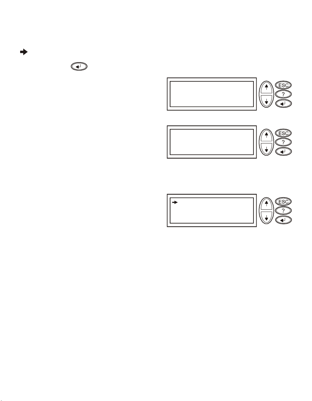
Navigating menu screens
Use the ESC key to navigate between menu screens.
Use the UP/DOWN arrow keys to scroll through the list of sub menus and commands on any screen.
arrow indicates that there are sub menus containing user selectable commands.
Use the ENTER key to navigate to a sub menu and to select user configurable commands.
To access the overview status screen on the LCD press
the ESC key.
To access the main menu screen from the overview status
screen, press the ENTER key.
Main Menu Screen
From the main menu screen it is possible to command, configure, and monitor the system using the sub menu
screens: Control, Status, Setup, Logging, Display, Diags and Help (refer to Sub menu screens section in this
manual).
Use the UP/DOWN arrow keys to select the menu to be
accessed.
Press the ENTER key to open a sub menu screen.
Chrg XXX%
Load XXX%
XXXVin XXXVou t XHz
1:1Runtime:XXhrXm
Control
Status
Setup
Batteries
Control
Status
Setup
Batteries
Logging
Display
Diags
Help
Logging
Display
Diags
Help
16 Smart-UPS RT 15000/20000 VA 230 Vac UXI/UXICH Tower User Manual
Page 21

Menu Tree
C
B
H
D
The menu tree provides an overview of the top level menu screens.
Chrg 000%
Overview Status
Screen
Load 000%
000Vin 000Vou t 0Hz
1:1Runtime:00hr0m
Control
Logging
Main Menu
Screen
ontrol
Status
Setup
Batteries
Status
Display
Logging
Display
Diags
Help
Setup
iags
atteries
elp
Navigating sub menu screens
Use the UP/DOWN arrow keys to scroll through the list of functions and commands on a sub menu screen.
A after the last entry on a sub menu, indicates a continuation of the function/command list.
Use the UP/DOWN arrow keys to view the remaining entries in the list.
Use the ENTER key to select a command and move to sub menus associated with that function/command.
Smart-UPS RT 15000/20000 VA 230 Vac UXI/UXICH Tower User Manual 17
Page 22

Sub menu screens
B
Control
Status
Setup
Batteries
UPS into Bypass
Do Self Test
Simulate Power Fail
Start Runtime Cal
Turn Load Off
Control
Status
Setup
Batteries
Settings:
Shutdown
Default
System
Shutdown
Default
Low Batt Dur
Shutdown Dly
Return Dly
Return Bat Cap
Set all UPS settings
to Factor y Defaults
NO, ABORT
YES, Set to Defaults
System
Logging
Display
Diags
Help
Logging
Display
Diags
Help
Alarms
Clock
Other
Voltage
Frequency
Frq. Range
1 Phase Mains On
Slew Rate
Cyclic Chrg
Auto Start
Control
Status
Setup
atteries
Vin Vbyp Vout
1
2
3
Iin Ibyp Iout
1
2
3
kW kVA
1
2
3
Frequencies
Mains
Bypass
Output
Load
Bat Voltage
Bat Charge
Runtime
Bat AmpHr
UPS Temp
Logging
Display
Diags
Help
Alarm Thresholds
Load
Runtime
Output Frequency Options: Auto Sensing; 50 Hz; 60 Hz
50 Hz frequency range: 50±3 Hz; 50±0.1 Hz
60 Hz frequency range: 60±3 Hz; 60±0.1 Hz
Alarms
Clock
Alarm Thre sholds
Load
Runtime
Date
Time
Other
Other Sett ings
Self Test
UPS ID
Ext Bat Cap
Clock: The date and time functions are used to time-stamp events
in the event log. To avoid inaccuracies, change the time setting to
reflect day light saving time where applicable.
Ext Bat Cap: Press . Use the UP/DOWN arrow keys to
select the desired value. Press to move to the next digit.
Press after selecting the final value, to lock in the battery
capacity setting.
18 Smart-UPS RT 15000/20000 VA 230 Vac UXI/UXICH Tower User Manual
Page 23

C
V
B
B
F
A
D
A
D
A
D
+
F
The Batteries menu is applicable only with an APC battery solution.
Control
Status
Setup
Batteries
Global Bat Status
Pack Status/Mfg
BatPair Status/Mfg
Global
Bat Status
Pack Status/Mfg
(with LED flashing
on selected frame)
+/-BatV
+/-BatI
Max Bat Temp
Charge
+Runtime:
-Runtime:
/-BatPair
+/-Bad
Packs
Bad
PC Battery
iagnostics
PC Battery
iagnostics
Logging
Display
Diags
Help
Control
Status
Setup
View Log
lear Log
iew Statistics
View Log
Clear Log
View
Statistics
atteries
Logging Menu
Time and Event of
last 100 entries
Confir m Clea r Log
Yes, Clea r Log
No, Abort
xxx Transfer s->B at.
xxx Transfer s->b yp.
xxxxxh r. I nv. Time
xxxhr xxmin on Bat
Logging
Display
Diags
Help
irmware Revision
MfgDate
Ser#
Model#
BattPair Status/Mfg
APC Battery
Diagnostics
PC Battery
iagnostics
Control
Status
Setup
atteries
Logging
Display
Diags
Help
ault & Diagnostics
System Information
Control
Status
Setup
Batteries
Logging
Display
Diags
Help
Fault &
Diagnostics
Switch Status
Raw Status Data
No Active al arms
Display Setup
Language
Contrast
Beeper Setup
Beeper Setup
Beeper at
Volume
System
Information
Raw Status
Data
System Information
FW-rev ision
SN
UPS Size
Raw Stat us Dump
M states =
Key Click
Smart-UPS RT 15000/20000 VA 230 Vac UXI/UXICH Tower User Manual 19
Page 24

Start-Up
Connect load to UPS
1. The UPS features chassis ground connection screws located on the rear panel, for connecting the ground
leads on transient voltage devices.
Prior to connecting the grounding cable, ensure that the UPS is NOT connected to utility or battery
power.
2. Connect equipment to the UPS.
NOTE: This UPS is equipped with an external battery connector on the rear panel of the unit.
• The battery charges to 90% capacity during the first three hours of normal operation. Do not expect
full battery run capability during this initial charge period.
• Refer to the APC Web site, www.apc.com for battery runtimes.
• Where appropriate use an APC extension battery cable. For ordering details contact your dealer or
APC through the Web site www.apc.com.
3. Add optional accessories to the SmartSlot located on the rear panel.
For optimal computer system security, install PowerChute Smart-UPS monitoring software.
Connect power to UPS and load
1. Connect input power to the UPS.
2. Check the PowerView interface display for messages.
3. Turn on the load using the interface display menu options.
– Bypass mode
– Turn Load On
Communication Ports
SERIAL PORT
20 Smart-UPS RT 15000/20000 VA 230 Vac UXI/UXICH Tower User Manual
Use only the supplied cable to connect to the serial port. A standard serial interface
cable is incompatible with the UPS.
The serial port can be used to configure tht Network Managegment Card.
Page 25

Emergency Power Off (EPO)
The output power can be disabled in an emergency by closing a switch connected to the EPO.
Adhere to national and local electrical codes when wiring.
The switch should be connected in a normally open switch contact. External voltage is not required; the switch
is driven by 12 V internal supply. In closed condition, 2 mA of current are drawn.
The EPO switch is internally powered by the UPS for use with non-powered switch circuit breakers.
The EPO circuit is considered a Class 2 circuit, (UL, CSA standards) and an SELV circuit (IEC standard).
EPO PORT
(located on rear panel)
Strip the insulation from one end of each wire to be used for connecting
EPO Connector
the EPO.
Insert a screwdriver into the slot above the terminal to be wired.
Insert the stripped end of the wire into the terminal.
Remove the screwdriver to secure the wire in the terminal.
Repeat for each terminal.
Both Class 2 and SELV circuits must be isolated from all primary circuitry. Do not connect any circuit to the
EPO terminal block unless it can be confirmed that the circuit is Class 2 or SELV. If circuit standard cannot be
confirmed, use a contact closure switch.
Use one of the following cable types to connect the UPS to the EPO switch.
• CL2: Class 2 cable for general use.
• CL2P: Plenum cable for use in ducts, plenums, and other spaces used for environmental air.
• CL2R: Riser cable for use in a vertical run in a floor-to-floor shaft.
• CLEX: Limited use cable for use in dwellings and for use in raceways.
• For installation in Canada: Use only CSA certified, type ELC, (extra-low voltage control cable).
• For installation in other countries: Use standard low-voltage cable in accordance with national and
local regulations.
Smart-UPS RT 15000/20000 VA 230 Vac UXI/UXICH Tower User Manual 21
Page 26

Troubleshooting Display Messages
Use the table below to solve minor installation and operation problems. Refer to the APC Web site,
www.apc.com for assistance with complex UPS problems.
The PowerView reports various messages on the display, including alarm status and changes in system
configuration. This section lists all the PowerView display messages, the reason for the message, and the
appropriate corrective action.
Messages may occur simultaneously. If this happens, be sure to review all of the messages for a better
understanding of the system condition.
Condition
Start-Up #Batteries changed since
PowerView Display
Message
last ON.
Automatic Self Test
Started.
Batt capacity less than
Return Batt Cap.
System Start-Up
Configuration Failed.
Mains: Site Wiring Fault Input and Output Jumpers are not
Bypass Not Available Wrong Ph Seq
Reason for Message Corrective Action
At least one battery module has been
added or removed from the UPS since
the last time the Pwr ON command
was issued.
The UPS has started pre-programmed
battery test.
The battery capacity of the UPS is less
than the user-specified minimum
battery capacity required to turn on
the load.
System configuration error: Start-up
diagnostic fault.
configured correctly
No corrective action necessary.
Proceed with the start-up.
Option 1) Abort the start-up and
allow batteries to recharge.
Option 2) Continue start-up, with less
than minimum battery capacity.
Check for other alarms.
If the problem persists contact APC
Customer Support. Refer to Contact
Information in this manual.
Check input wiring tray jumpers and
output shorting jumper for
compatibility. Refer to the Input/
Output Jumper Configurations table
in this manual.
Check bypass jumpers in input
wiring tray and output shorting
jumper for compatibility. Check
bypass phases for positive sequence.
Refer to the Input/Output Jumper
Configurations table in this manual.
Bypass: Site Wiring Fault Check bypass jumpers in input
22 Smart-UPS RT 15000/20000 VA 230 Vac UXI/UXICH Tower User Manual
wiring tray and output shorting
jumper for compatibility. Refer to the
Input/Output Jumper Configurations
table in this manual.
Page 27

Condition
PowerView Display
Message
Reason for Message Corrective Action
General
Status
Module
Failure
Threshold
Alarm
# of batteries increased. At least one battery pair has been
# of batteries decreased. At least one battery pair has been
# External Battery Packs
increased.
# External Battery Packs
decreased.
Bad Battery Pair. A battery pair has failed and requires
Load Power Is Above
Alarm Limit.
Load Is No Longer Above
Alarm Threshold.
Min Runtime Restored. The system runtime dropped below
added to the system.
removed from the system.
At least one external battery pack has
been connected to the UPS.
At least one external battery pack has
been disconnected from the UPS.
replacement.
The load has exceeded the userspecified load alarm threshold.
The load exceeded the alarm
threshold. The situation has been
corrected. Either because the load
decreased or the threshold was
increased.
the configured minimum and has been
restored:
1) Additional battery modules were
installed.
2) The existing battery modules were
recharged.
3) The load was reduced.
4) The user- specified threshold was
decreased.
No corrective action is necessary.
Refer to battery pair installation in
the external battery pack user
manual.
Option 1) Use the display interface to
raise the alarm threshold.
Option 2) Reduce the load
No corrective action is necessary.
Smart-UPS RT 15000/20000 VA 230 Vac UXI/UXICH Tower User Manual 23
Page 28

Condition
PowerView Display
Message
Reason for Message Corrective Action
General
Fault
Need Bat Replacement. One or more battery pairs are in need
No Batteries Are
Connected.
Discharged Battery. The UPS is on battery operation and
Low- Battery. The UPS is on battery operation and
Weak Batt(s) Detected.
Reduced Runtime.
Batt Temperature Exceeded
Upper Limit.
Battery Over-Voltage
Warning.
Runtime Is Below Alarm
Threshold.
of replacement.
No battery power is available. Check that batteries are installed and
the battery charge is low.
the battery charge is low.
One or more weak battery pairs
detected (only applicable for internal
battery modules).
The temperature of one or more
battery pack has exceeded system
specifications.
The battery voltage is too high and the
charger has been deactivated.
The predicted runtime is lower than
the user-specified minimum runtime
alarm threshold. Either the battery
capacity has decreased, or the load has
increased.
Refer to battery installation
procedure.
connected properly.
Shut down the system and the load
or restore the incoming voltage.
Replace the weak battery pairs.
Contact APC Customer Support.
Refer to Contact Information in this
manual.
Option 1) Allow the batteries to
recharge.
Option 2) If possible, increase the
number of battery modules.
Option 3) Reduce the load.
Option 4) Decrease the alarm
threshold.
24 Smart-UPS RT 15000/20000 VA 230 Vac UXI/UXICH Tower User Manual
Page 29

Condition
PowerView Display
Message
Reason for Message Corrective Action
General
Fault
Shutdown Due To Low
Battery.
Bypass Not Available Input
Freq/Volt out Of Range.
Mains Not Available. Input
Frq/Volt Out of Range.
Emergency PSU Fault. Redundant Emergency Power Supply
Fan Fault A fan has failed. Contact APC Customer Support.
Static Bypass Switch Fault. The static bypass switch has failed.
System Failure Detected by
Surveillance.
System Not Synchronized
to Bypass.
The UPS shutdown while on battery
operation.
The frequency or voltage is out of
acceptable range for bypass. This
message occurs when the UPS is
online.
The frequency or voltage is out of
acceptable range for normal
operation.
Unit (PSU) is not working. Internal
diagnostic fault. The UPS will
continue to operate normally.
The system has detected an internal
error.
System cannot synchronize to bypass
mode.Bypass mode may be
unavailable.
No corrective action is necessary.
Note: Should this situation reoccur,
consider increasing battery capacity.
Correct the input voltage to
acceptable frequency or voltage.
Contact APC Customer Support.
Refer to Contact Information in this
manual.
Refer to Contact Information in this
manual.
Check for other alarms.
If the problem persists contact APC
Customer Support. Refer to Contact
Information in this manual.
Option 1) Decrease input frequency
sensitivity.
Contact APC Customer Support.
Refer to Contact Information in this
manual.
Option 2) Correct bypass input
voltage to provide acceptable
frequency or voltage.
UPS In Bypass Due To
Fault.
UPS In Bypass Due To
Overload.
UPS Is Overloaded. The load has exceeded the system
Smart-UPS RT 15000/20000 VA 230 Vac UXI/UXICH Tower User Manual 25
The UPS has transferred to bypass
mode due to a fault.
The load has exceeded the power
capacity.
power capacity.
Contact APC Customer Support.
Refer to Contact Information in this
manual.
Decrease the load.
Option 1) Decrease the load.
Option 2) Check the load distribution
on the three phases through the
PowerView display. If the load is
unevenly distributed, adjust the load
distribution.
Page 30

Service and Transport
If the unit requires service do not return it to the dealer. Follow these steps:
1. Review the problems discussed in the Troubleshooting section to eliminate common problems.
2. If the problem persists, contact APC Customer Support through the
APC Web site, www.apc.com.
– Note the model number of the unit, the serial number located on the back of the unit, and the date
purchased. If you call APC Customer Support, a technician will ask you to describe the problem
and attempt to solve it over the phone. If this is not possible, the technician will issue a Returned
Material Authorization Number (RMA#).
– If the unit is under warranty, repairs are free.
– Procedures for servicing or returning products may vary internationally. Refer to the APC Web
site for country specific instructions.
3. Pack the unit in its original packaging. If this is not available:
– Pack the unit carefully to avoid damage in transit. Never use Styrofoam beads for packaging.
Damage sustained in transit is not covered under warranty.
4. Always DISCONNECT THE UPS BATTERY before shipping in compliance with U.S. Department
of Transportation (DOT) and IATA regulations. The battery(s) may remain in the unit.
5. Mark the RMA# on the outside of the package.
6. Return the unit by insured, prepaid carrier to the address given to you by Customer Support.
26 Smart-UPS RT 15000/20000 VA 230 Vac UXI/UXICH Tower User Manual
Page 31

Two-Year Warranty
The limited warranty provided by American Power Conversion (APC®) in this statement of Limited Factory Warranty applies only to
products you purchase for your commercial or industrial use in the ordinary course of your business.
Terms of warranty
APC warrants its products to be free from defects in materials and workmanship for a period of two years from the date of purchase. The
obligation of APC under this warranty is limited to repairing or replacing, at its sole discretion, any such defective products. This warranty
does not apply to equipment that has been damaged by accident, negligence or misapplication or has been altered or modified in any way.
Repair or replacement of a defective product or part thereof does not extend the original warranty period. Any parts furnished under this
warranty may be new or factory-remanufactured.
Non-transferable warranty
This warranty extends only to the original purchaser who must have properly registered the product. The product may be registered at the
APC Web site, www.apc.com.
Exclusions
APC shall not be liable under the warranty if its testing and examination disclose that the alleged defect in the product does not exist or was
caused by end user or any third person misuse, negligence, improper installation or testing. Further, APC shall not be liable under the
warranty for unauthorized attempts to repair or modify wrong or inadequate electrical voltage or connection, inappropriate on-site
operation conditions, corrosive atmosphere, repair, installation, start-up by non-APC designated personnel, a change in location or
operating use, exposure to the elements, Acts of God, fire, theft, or installation contrary to APC recommendations or specifications or in
any event if the APC serial number has been altered, defaced, or removed, or any other cause beyond the range of the intended use.
THERE ARE NO WARRANTIES, EXPRESS OR IMPLIED, BY OPERATION OF LAW OR OTHERWISE, OF PRODUCTS SOLD,
SERVICED OR FURNISHED UNDER THIS AGREEMENT OR IN CONNECTION HEREWITH. APC DISCLAIMS ALL IMPLIED
WARRANTIES OF MERCHANTABILITY, SATISFACTION AND FITNESS FOR A PARTICULAR PURPOSE. APC EXPRESS
WARRANTIES WILL NOT BE ENLARGED, DIMINISHED, OR AFFECTED BY AND NO OBLIGATION OR LIABILITY WILL
ARISE OUT OF, APC RENDERING OF TECHNICAL OR OTHER ADVICE OR SERVICE IN CONNECTION WITH THE
PRODUCTS. THE FOREGOING WARRANTIES AND REMEDIES ARE EXCLUSIVE AND IN LIEU OF ALL OTHER
WARRANTIES AND REMEDIES. THE WARRANTIES SET FORTH ABOVE CONSTITUTE APC SOLE LIABILITY AND
PURCHASER EXCLUSIVE REMEDY FOR ANY BREACH OF SUCH WARRANTIES. APC WARRANTIES EXTEND ONLY TO
PURCHASER AND ARE NOT EXTENDED TO ANY THIRD PARTIES.
IN NO EVENT SHALL APC, ITS OFFICERS, DIRECTORS, AFFILIATES OR EMPLOYEES BE LIABLE FOR ANY FORM OF
INDIRECT, SPECIAL, CONSEQUENTIAL OR PUNITIVE DAMAGES, ARISING OUT OF THE USE, SERVICE OR
INSTALLATION, OF THE PRODUCTS, WHETHER SUCH DAMAGES ARISE IN CONTRACT OR TORT, IRRESPECTIVE OF
FAULT, NEGLIGENCE OR STRICT LIABILITY OR WHETHER APC HAS BEEN ADVISED IN ADVANCE OF THE POSSIBILITY
OF SUCH DAMAGES. SPECIFICALLY, APC IS NOT LIABLE FOR ANY COSTS, SUCH AS LOST PROFITS OR REVENUE, LOSS
OF EQUIPMENT, LOSS OF USE OF EQUIPMENT, LOSS OF SOFTWARE, LOSS OF DATA, COSTS OF SUBSTITUENTS, CLAIMS
BY THIRD PARTIES, OR OTHERWISE.
NO SALESMAN, EMPLOYEE OR AGENT OF APC IS AUTHORIZED TO ADD TO OR VARY THE TERMS OF THIS WARRANTY.
WARRANTY TERMS MAY BE MODIFIED, IF AT ALL, ONLY IN WRITING SIGNED BY AN APC OFFICER AND LEGAL
DEPARTMENT.
Warranty claims
Customers with warranty claims issues may access the APC customer support network through the Support page of the APC Web site,
www.apc.com. Select your country from the country selection pull-down menu. Open the Support tab at the top of the Web page to obtain
contact information for customer support in your region.
Smart-UPS RT 15000/20000 VA 230 Vac UXI/UXICH Tower User Manual 27
Page 32

Contact Information
APC Worldwide Customer Support
Customer support for this or any other APC product is available at no charge in any of the following ways:
• Refer to the APC Web site to access documents in the APC Knowledge Base and to submit customer
support requests.
– www.apc.com (Corporate Headquarters)
Connect to localized APC Web sites for specific countries, each of which provides customer
support information.
– www.apc.com/support/
Global support searching APC Knowledge Base and using e-support.
• Contact an APC Customer Support center by telephone or e-mail.
Local, country-specific centers:
go to www.apc.com/support/contact for information.
Contact the APC representative or other distributor from whom you purchased your APC product for
information on how to obtain local customer support.
Regulatory Agency Approvals
230 V models
geprüfte
N 394
Entire contents copyright 2007 American Power Conversion Corporation. All rights reserved. Reproduction in whole or in part without
permission is prohibited.
APC, the APC logo, Smart-UPS and PowerChute are trademarks of American Power Conversion Corporation. All other trademarks,
product names, and corporate names are the property of their respective owners and are used for informational purposes only.
Sicherheit
28 Smart-UPS RT 15000/20000 VA 230 Vac UXI/UXICH Tower User Manual
 Loading...