

Page 1

Section 1
(1) AR8200 Index
(1) Index ............................................................................................................................ 1
1-1 Introduction .................................................................................................................. 5
1-2 Take care of your radio ................................................................................................ 5
1-3 Attention while operating ............................................................................................. 6
1-4 Accessories supplied ................................................................................................... 7
1-5 Controls & functions .....................................................................................................8
1-5-1 Keypad ..................................................................................................................... 9
1-5-2 Summary of keys ...................................................................................................... 10
1-5-3 Side panel ................................................................................................................. 15
1-6 Power supply and battery charging ............................................................................. 16
1-6-1 Internal batteries ....................................................................................................... 16
1-6-2 Charging the NiCads ................................................................................................ 18
1-6-3 Cigar lighter lead ...................................................................................................... 18
1-6-4 Battery considerations .............................................................................................. 19
(2) Making the AR8200 ready for operation ................................................................... 20
2-1 LCD (Liquid Crystal Display) ....................................................................................... 20
2-2 Connect the aerial (antenna) ....................................................................................... 21
2-3 Fit the batteries ............................................................................................................ 21
2-4 Keypad and knobs... what you need to know ‘most’ .................................................... 22
2-4-1 ENTER key ............................................................................................................... 22
2-4-2 FUNCTION key ......................................................................................................... 22
2-4-3 PASS key .................................................................................................................. 22
2-4-4 CLEAR key ............................................................................................................... 23
2-4-5 MONITOR key .......................................................................................................... 23
2-4-6 KEY lock ................................................................................................................... 23
(3) Basic manual operation of the receiver .................................................................... 24
3-1 Switching On ............................................................................................................... 24
3-2 2VFO twin VFO selection ............................................................................................ 24
3-3 Entering a frequency using the numeric keypad ......................................................... 26
3-4 Correcting frequency input .......................................................................................... 27
3-5 Changing frequency using the ñ and ò keys .............................................................. 28
3-6 Changing frequency using the main dial ..................................................................... 28
3-7 Changing receive mode ............................................................................................... 29
3-7-1 Auto-mode selection ................................................................................................. 29
3-7-2 Receive mode selection menu ................................................................................. 29
3-8 Changing tuning STEP size ......................................................................................... 31
3-9 STEP-adjust ................................................................................................................ 33
3-9-1 Automatic calculation of step adjust ......................................................................... 33
3-9-2 Cancelling step adjust .............................................................................................. 34
3-9-3 Manual setting of step adjust .................................................................................... 34
3-10 FREQUENCY OFFSET .............................................................................................. 36
3-10-1 Using pre-programmed frequency offset data ........................................................ 36
3-10-2 Entering new frequency offset data ........................................................................ 37
3-11 Attenuator .................................................................................................................. 38
3-12 Noise limiter ............................................................................................................... 38
3-13 AFC - Automatic Frequency Control .......................................................................... 39
(4) VFO enhanced facilities ............................................................................................. 41
4-1 Quick memories ...........................................................................................................41
4-1-1 Saving quick memory data ....................................................................................... 41
4-1-2 Recalling quick memories ........................................................................................ 42
4-2 VFO scan .................................................................................................................... 42
4-2-1 VFO SCAN sampling time ........................................................................................ 43
4-3 VFO Search ................................................................................................................. 43
4-3-1 Defining VFO search ................................................................................................ 43
1
Page 2

®
AR8200 SERIES II - hand portable radio receiver ADDENDUM (paperwork V1.0)
Due to continuous development of our products, the AR8200 SERIES II has been developed which differs from the original
AR8200 in a few areas, please note the following changes to the AR8200 operating manual:
1 The front ‘ten-key’ keypad has been rearranged in line with customer requests placing the ‘0’ zero key underneath the
‘8’ eight key as standard practice with push button telephones. On page 9 section 1-5-1 of the English language operating
manual, the graphic should now look like:
2 The AR8200 SERIES II now features a built-in TCXO (Temperature Controlled Crystal Oscillator) in place of the reference
crystal. This ensures the best levels of frequency stability and minimum spurii.
3 In place of the previous rubber covered compact whip aerial is a telescopic whip on a swivel base. This provides the very
best performance, especially on the VHF bands with the ability to adjust the length of the telescopic whip aerial to ‘peak’
received signal strength (the higher the frequency, the shorter the aerial). An alternative flexible smaller whip aerial (DA900) is
available as an option where durability and smaller size is important. Please refer to page 7 section 1-4 of the English
language operating manual, line two of the table should now read “telescopic whip aerial”
4 The relationship between level squelch and signal meter has been revised. This affects VFO SEARCH LEVEL SQUELCH
(page 47 section 4-4-3 of the English language operating manual), SCAN LEVEL SQUELCH (page 68 section 7-8-2 of the
English language operating manual) and PROGRAM SEARCH LEVEL SQUELCH (page 84 section 8-7-2 of the English
language operating manual).
In each case, the following table replaces that previously employed:
1 2 3 4 5 6 7 8 9 10 11 12 13 14
8 13 18 24 29 35 39 44 50 55 58 62 71 77
The typical level at which the “
«” legend will be extinguished is now in the region of 5 - 60.
5 High capacity NiCads are supplied with the AR8200, to ensure that a completely full charge is established, please assume
the full charge time of 14 hours, this replaces the reference to 12 hours given on page 19 section 1-6-4 of the English language
operating manual.
6 The design of the battery compartment and compartment cover has been revised to assist the easy replacement of batteries,
refer to page 16 section 1-6-1 of the English language operating manual. The cabinet colour of the AR8200 has also been
changed from green to black.
AOR LTD, 2-6-4 Misuji, Taito-Ku, Tokyo 111-0055, Japan Tel: +81 3 3865 1695 Fax: +81 3 3865 1697
e-mail: post@aorja.com web: www.aorja.com
Page 3

Section 13-3
13-3 Short cut text entry, keypad with ïðñò keys
Text may also be entered using a combination of the keypad and ï ð ñ ò keys.
While in a text input menu, for flashing “FUNC” legend then refer to the following table.
Look for the required character in the table then PUSH the key shown to the horizontal-left followed by
the ï ð ñ ò key shown above the required character (do not push both keys together). The first key
push will produce a character on the screen which will be replaced with the required character when the
second key is pushed, the cursor with then move one place to the right.
&Note: The CASE SHIFT key is used to access lower case letters.
Example:
displayed and the cursor will move one position to the right. The
flash, if it is not required further for it to be removed from the LCD.
Example:
case letter is required (CASE SHIFT) ñ, the desired “e” character will be displayed and the
cursor will move one position to the right. The
required further for it to be removed from the LCD.
To select the letter “N” until the
, the number “4” will be displayed, ï, the desired “N” character will be
To select the letter “e” until the
, the number “5” will be displayed, to instruct the CPU that a lower
flashing
flashing
“FUNC” is displayed.
flashing
“FUNC” legend will continue to
flashing
“FUNC” is displayed.
“FUNC” legend will continue to flash, if it is not
105
Page 4

Section 14, 14-1, 14-2
(14) Configuration menu
The configuration (CONFIG) menu is used to set fundamental operating parameters and other variables
which do not appear in any other menu heading.
BEEP Confirmation & error tone
LAMP LCD & keypad illumination
CONTRAST LCD contrast adjustment
POWER-SAVE Delay & cycle power save
AUTO PWR-OFF Auto inactivity power off
REMOTE BPS RS232 baud rate
RMT-ID Computer control address
FREQ DISP Frequency readout on/off
WRITE PROT Global write protect
OPENING MESSAGE Change the power-up message
14-1 CONFIG BEEP
The AR8200 emits confirmation ‘beeps’ while the keypad and side
keys are used. A ‘HIGH’ pitched beep indicates correct operation
while a ‘LOW’ pitched beep indicates that an error or unexpected
entry has taken place. The volume of the beep is independent of
the main volume control and can be separately defined. It is
recommended that the beep facility be enabled, especially in the
early days while gaining familiarity of the receiver.
Beep is setup in the CONFIG menu. To access the config
menu . The first item in the
config menu is “BEEP”, the default is beep on with a volume level of 09. Use the main dial or ï ð
keys to vary beep level between the range of OFF and 01 to 09 with 09 being the loudest. The
key may be used as a short cut to 05.
to accept the data and return to a standard display. Alternatively
to abort entry or ò to move to the next item on the config menu (LAMP).
14-2 CONFIG LAMP
The AR8200 is equipped with high intensity green LEDs to illuminate the LCD and front panel keypad
when operating in areas of low level lighting.
While the AR8200 is switched on and connected to an external power source such as the charger
or d.c. lead, the lamp will be PERMANENTLY ON and
when the AR8200 is switched off (when the batteries are being charged etc).
cannot be switched off
. The lamp will go out
106
Page 5

Section 14-2, 14-3
The lamp may be configured in three ways:
AUTO
This setting is relevant when operating from internal batteries only. The lamp will automatically illuminate
when the front panel and side panel keys are used. The lamp will remain illuminated for a further five
second after the last key push and will then switch off. This is a good compromise setting for best
visibility and battery life.
CONT
This setting is relevant when operating from internal batteries only. The lamp will CONTinuously
illuminate the front panel and side panel keys. The lamp will only extinguish when the AR8200 is
switched off. Of course continuous operation of the lamp will drain the internal batteries more quickly.
OFF
This setting is relevant when operating from internal batteries only. The lamp remains permanently
extinguished, this is useful to maintain maximum battery life when used in areas of high light levels.
The LAMP is setup in the CONFIG menu. To access the config menu
. ò to move the cursor to the “LAMP” selection point. Use the main dial or ï ð
keys to toggle the lamp between AUTO (default), CONT and OFF. The key may be used
as a short cut to AUTO.
to accept the data and return to a standard display. Alternatively
to abort entry or ò to move to the next item on the config menu (CONTRAST).
14-3 CONFIG CONTRAST
The AR8200 is equipped with variable LCD contrast which is adjustable in 32 steps to provide best
visibility under different viewing angles, extremes of ambient light & temperature (and between sets due
to variation).
The default setting for contrast is 14. The display generally becomes too dark to read around 20 and too
feint around 02, the key may be used as a short cut to 14.
The CONTRAST is setup in the CONFIG menu. To access the config menu
. ò twice to move the cursor to the “CONTRAST” selection point. Use the
main dial or ï ð keys to vary the contrast level to achieve best visibility.
to accept the data and return to a standard display. Alternatively
to abort entry or ò to move to the next item on the config menu (POWER-SAVE).
107
Page 6

Section 14-4
14-4 CONFIG Power save
The POWER SAVE facility may be used to help the receiver to operate for longer periods of time
between battery recharging. Power save is default OFF to prevent confusion while the AR8200 is in a
“dormant” cycle as the receiver is effectively asleep and only wakes up for short periods to check for
activity before going to sleep and becoming dormant again.
&Note: While in a dormant state (waiting to cycle), the AR8200 behaves sluggishly.
When power save is ON, the AR8200 will automatically switch ‘off and on’ but the display will appear
permanently on as only the AR8200 “receive” circuitry is switched off and on (switching the receiver off
for short periods of time is what saves power!), the microprocessor is left on permanently but in a
reduced operating condition.
When activated, two parameters may be varied to affect the way the receiver behaves, these are
“DELAY” and “CYCLE”.
DELAY: This parameter determines how long the AR8200 will remain active before going to
sleep and becoming dormant and is timed from when the squelch last closed or keypad was last
used. The available range is 01 to 30 seconds plus OFF (default off). When OFF, the power
save does not operate. The key may be used as a short cut to OFF.
CYCLE: When the receiver becomes dormant (delay has expired), the cycle parameter
determines how long the AR8200 will remain dormant before its ‘wake up’ period begins. If a
transmission takes place while dormant it will be missed, if however a transmission occurs
during the wake up period, the AR8200 will continue to monitor until the transmission ends and
DELAY / CYCLE takes place again. The available range is 0.5 to 9.5 seconds (default 3.0
seconds). The key may be used as a short cut to 3.0 seconds.
The POWER SAVE parameters are setup in the CONFIG menu. To access the config menu
. ò three times to move
the cursor to the POWER SAVE “DELAY” selection point. Use the
main dial or ï ð keys to vary the delay value, the key
may be used as a short cut to OFF.
ò to move the cursor to the POWER SAVE “CYCLE”
selection point.
108
Page 7

Section 14-4, 14-5, 14-6
Use the main dial or ï ð keys to vary the cycle value, the key may be used as a short cut
to 3.0 seconds.
to accept the data and return to a standard display. Alternatively
to abort entry or ò to move to the next item on the config menu (AUTO PWR-OFF).
14-5 CONFIG Auto power off
An auto power off facility is available to switch the AR8200 off automatically after a programmable period
of squelch inactivity, this prevents the batteries from becoming flat when monitoring a completely inactive
frequency.
&Note: Be careful how you use auto power off as it might catch you out one day (if a short
auto-power-off period has been set), auto power off setting is not cancelled with power off / on…
if the AR8200 appears to switch itself off for no reason, check to make sure that you haven’t
enabled auto power off (there is no associated LCD legend).
AUTO POWER OFF is setup in the CONFIG menu. To access the
config menu . ò five
times to move the cursor to the “AUTO PWR-OFF” selection point.
Use the main dial or ï ð keys to vary the time between 0.5 hours
to 9.5 hours in 0.5 hr increments, the key may be used
as a short cut to OFF.
When the AR8200 squelch closes, the CPU will wait the length of
time programmed in auto-power-off before automatically switching
the AR8200 off. If the squelch opens again before auto switch off time has elapsed, the radio will not
power down and the counter will be reset (i.e. an open squelch defeats auto power off).
to accept the data and return to a standard display. Alternatively
to abort entry or ò to move to the next item on the config menu (REMOTE BPS).
14-6 CONFIG REMOTE BPS
The REMOTE BPS menu is used to configure the RS232 computer control settings as it is important that
they exactly match those of an associated computer connection or another AR8200 (connected via the
option socket and optional leads).
The REMOTE BPS parameters are setup in the CONFIG menu.
To access the config menu .
ò six times to move the cursor to the “REMOTE BPS”
selection point. Use the main dial or ï ð keys to vary the RS232
baud rate between 4800bps, 9600bps and 19200bps. The
key may be used as a short cut to the default of
9600bps.
109
Page 8

Section 14-6, 14-7, 14-8
ò to move the cursor to the “RMT-ID” selection point. Use the main dial or ï ð keys
change the AR8200 RS232 IDENTIFICATION ADDRESS when multiple units are connected to the
same port.
It is possible to connect up to 99 units at once, each radio being assigned a different address. The value
is adjustable between 00 and 99, the default is 00. The key may be used as a short cut 00.
&Important note: It is extremely important to set the RMT-ID to 00 for normal operation
of the RS232 connection and clone of data between radios.
to accept the data and return to a standard display. Alternatively
to abort entry or ò to move to the next item on the config menu (FREQ DISP).
14-7 CONFIG FREQ DISP
It is possible to instruct the AR8200 NOT to display frequencies while in memory read, search and scan
modes (should you wish for prying eyes not to see specifically what you are listening to). Liberal use of
‘text comments’ is recommended if you disable frequency display (turned it off) unless you choose to
have really anonymous operation!
&Note: Frequency display will be provided in VFO and VFO search and VFO scan even with
the frequency display disabled.
The FREQUENCY DISPLAY parameters are setup in the CONFIG
menu. To access the config menu .
ò eight times to move the cursor to the “FREQ DISP”
selection point. Use the main dial or ï ð keys to toggle between
ON and OFF. The key may be used as a short cut to ON
(which is default).
to accept the data and return to a standard display. Alternatively
to abort entry or ò to move to the next item on the config menu (WRITE PROT).
14-8 CONFIG GLOBAL write protect
It is possible to globally write protect the entire AR8200 data storage, this prevents memory entry, search
bank programming, loading of data via the option socket, loading of data from the optional EM8200 etc.
Use this feature carefully.
Should you wish to leave your AR8200 safe in the knowledge that no-one will ‘mess it up’ (well
maybe!)… toggle global write protect on.
The global “WRITE PROTECT” status is setup in the CONFIG menu. To access the config menu
. ò nine times to move the cursor to the “WRITE PROT”
selection point.
110
Page 9

Section 14-8, 14-9
Use the main dial or ï ð keys or key to toggle between ON and OFF (the default is off).
to accept the data and return to a standard display. Alternatively
to abort entry or ò to move to the next item on the config menu (OPENING MESSAGE).
14-9 CONFIG Opening message
It is possible to display a welcome message while the AR8200 is powering up and collating its ‘boot-up’
information. There are three options for opening message:
NORM
Normal message is displayed at switch-on: WELCOME TO THE NEW WORLD OF AR8200.
QUICK
Blank screen at switch-on.
USER
Four lines of 12 characters may be entered for display at switch-on. Initially they are configured
for you to enter OWNERS name and PHONE NUMBER but all lines may be over-written.
The “OPENING MESSAGE” is setup in the CONFIG menu.
To access the config menu .
ò ten times to move the cursor to the
“OPENING MESSAGE” selection point. Use the main dial or
ï ð keys to toggle between NORM / QUICK / USER.
The key may used as a short cut to NORM (which is
the default).
to accept the data and return to a standard display
or to abort entry.
Alternatively if you have selected
text input menu for the opening menu.
You may change all four lines of text in the usual
manner. Please refer to
manual for further information regarding text input.
to accept the data and return to
a standard display or to abort
entry. When the AR8200 is switched off and back
on again, the new opening message will be
displayed.
USER
section 12-1
and wish to change the text comment ò to access the
of this
111
Page 10

Section 15, 15-1
(15) Band scope
The AR8200 is equipped with a flexible band scope function which is capable of graphically displaying
band activity. The maximum frequency span width is 10 MHz, you may zoom in on activity to a span
width of 100 kHz. Centre frequency is displayed and a marker may be manipulated to ascertain the
frequency of activity using the graphical display. One trace may be saved to memory for recall at a later
time and may be overwritten at will. The trace may also be saved and loaded from the optional EM8200
external memory slot card.
&Note: Priority operation is disabled when the band scope is in operation. Audio is muted.
The optional RU8200 is inoperative when the band scope is in operation.
It is suggested that the band scope facility is ‘experimented with’ on a constantly active band such as
VHF Band-II broadcast.
15-1 Starting the band scope
To start the band scope . The frequency span width will be set to 10 MHz with the last
frequency displayed in 2VFO, search, scan or memory read mode being used as the centre frequency.
AUDIO IS MUTED.
The centre frequency is displayed in the top left of the LCD, one pixel will be missing from the centre of
the graphical base line indicating centre frequency position.
A progress cursor which comprises of a single pixel on the graphical base line travels from left to right
updating the band scope display… this confirms that the band scope is IN OPERATION (especially
useful when a trace is simply being updated or no signals have been located).
The frequency span width is displayed in the upper right corner of the LCD, at default this is 10 MHz.
The frequency marker legend “MKR” is displayed on the second line of the LCD, the marker is also
represented graphically by an upturned triangle (initially placed above-centre of the graphical trace).
When first activated, the centre and marker frequencies are the same (but may be altered).
The graphical trace is built-up from left to right. If no transmissions are encountered the display will
simply form a horizontal line around two pixels in height. When activity is located, vertical lines are
produced on the LCD, the stronger the signal the higher the line.
&Important: To monitor the transmission of the marker frequency and hold the
key. The progress of the scope is halted when the key is held. Squelch setting
has no effect on the band scope trace.
112
Page 11

Section 15-2, 15-3, 15-4, 15-5
15-2 Exit from band scope
To exit the band scope or or .
15-3 Setting frequency span width (waveform enlargement)
The frequency span width may be adjusted between the limits of 10 MHz (default) to 100 kHz using
the ñ ò keys. The span widths available are:
10 MHz 35s for full trace approx.
5 MHz 20s for full trace approx.
2 MHz 10s for full trace approx.
1 MHz 6s for full trace approx.
500 kHz 3s for full trace approx.
200 kHz 6s for full trace approx.
100 kHz. 3s for full trace approx.
When the frequency span width is altered, the trace restarts. to refresh the trace from
the start.
Resolution is 10 kHz with a 12 kHz IF
filter selected (NFM or AM) so that one
pixel represents 140 kHz at maximum
signal strength
Resolution is 2 kHz with a
3 kHz filter (USB, LSB, CW)
15-4 Moving the marker
To move the marker position use the ï ð keys, the channel step will be dependant upon the span
width resolution. To monitor the marker frequency and hold the key. The progress of
the scope is halted when the key is held.
15-5 Marker to strongest signal (peak search)
To simplify operation, it is possible to ‘jump the marker’ to the strongest signal of the current graphical
trace (peak search). and hold the key until the “«” legend is displayed indicating
that the marker is set to the strongest graphical signal. and hold the key to monitor
the selected frequency. The ï ð keys may be used to hop between the strongest few transmissions.
to disable peak search, the “«” will be removed from the LCD.
&Note: If no signal is found above the background level (or if there hasn’t been time allowed
for a trace to form), peak search will not operate and an error beep will be emitted (if beep is
enabled). This facility cannot be used with a span width of 100 kHz.
113
Page 12

Section 15-6, 15-7, 15-8, 15-9
15-6 Entering a new centre frequency
To enter a new centre frequency, simply tap the wanted frequency into the keypad. The legend
“CENTRE FREQ” will be displayed on the top line of the LCD with entry taking place on the second line.
To complete entry in MHz format . The marker will be automatically set to the centre
frequency but the frequency span width will be unchanged.
15-7 Transfer of marker frequency to VFO
There are two ways in which the marker frequency may be transferred to VFO for long term monitoring.
Transfer to 2VFO retaining VFO data
to move marker frequency to 2VFO, receive mode and step
are those of the VFO.
Transfer to single VFO with 10 kHz tuning step
Hold the key then to transfer marker frequency to single VFO,
receive will be that used in VFO mode but the tuning step will always be 10 kHz to allow
sensible re-tuning in VFO mode for best reception of the transferred marker frequency
15-8 Peak hold
The PEAK HOLD facility is used to build up an image of band
activity over a period of time, the display is not totally cleared each
time a trace is made, only strong signals are added.
To toggle PEAK HOLD on/off ,
the “HLD” legend confirms when peak hold is active.
The ï ð keys may be used to move the marker position and
key may be held to monitor activity on the marker
frequency.
15-9 Saving active trace to memory
To save the current trace to internal memory (for later retrieval)
. It is suggested that the peak hold facility
be employed before saving a trace so that it provides more
meaningful information.
If the optional EM8200 is used, it possible to save four further
traces to external memory. Refer to
for further information regarding this feature.
section 18-6-7
of this manual
114
Page 13

Section 15-10
15-10 Loading stored band scope traces from memory
Providing a trace has been previously stored to memory, it is possible to recall it to display using the key
sequence . The legend “RCV” (in the place of “MKR”) indicates that a
stored trace is currently being displayed.
The AR8200 will no longer sweep the frequency range but the key may still be used to monitor
the marker frequency. Key in a new centre frequency to return to a real time band scope.
It is possible to move the marker across the graphical trace using the ï ð keys. Waveform enlargement
is available by changing the frequency sweep width using the ñ ò keys.
If the optional EM8200 is used, it possible to load any one of four
further traces from external memory. Refer to
this manual for further information regarding this feature.
section 18-6-7
of
115
Page 14
Section 16
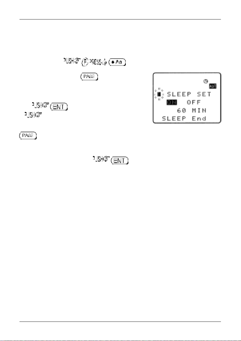
(16) Sleep ¹
It is possible to instruct the AR8200 to automatically switch-off after a predetermined time, this is
particularly useful if you know that you may be called away from the receiver or listen to it while in
bed and don’t want the batteries to become completely flat.
Use the key sequence to accesses the SLEEP menu.
Use the main dial, ï ð keys or key to toggle sleep
on/off. For convenience SLEEP is default ON when this menu is
accessed so that you have simply to access and exit the menu for
sleep to be activated.
Either to save the changes and exit the menu
or ò to move the cursor to the sleep TIME menu. Use
the main dial to set sleep time in 1s increments or ï ð keys to
increment in 10 seconds, the range is between 1 and 120 minutes,
is a short cut to 60 minutes (default).
The AR8200 will automatically switch off after the programmed time has elapsed.
To accept the data and activate sleep . The display will return to standard format and
the circular CLOCK legend ¹ will be displayed to remind you that automatic power off will take place.
The next time that the AR8200 is powered on, the sleep facility will be automatically cancelled.
116
Page 15

(17) Option socket
The option socket is mounted on the right hand side of the cabinet
underneath the 12V d.c. input socket. The socket is protected from
dust by a grey rubberised case stopper which is hinged toward the
front of the cabinet. Gently lift the stopper from the rear edge to
reveal the D-shaped metallic socket. Be careful to keep dust and dirt
from this socket and to prevent liquid entering the AR8200 via this
socket. Ensure that no conductive material is allowed to short circuit the
socket which may damage the receiver.
The option socket has three main uses:
1. Connection of the optional CR8200 tape recording lead
2. Connection of the optional CO8200 data clone lead
3. Connection of the optional CC8200 computer control lead with level
shift (available with imperial (PC98) & metric (DOSV) screws)
Other signals are available via the option socket including detector output, mute and AGC.
Typical pin-out of the optional leads are as follows:
RED +4.2V
BLACK RXD
BLUE GROUND
BROWN MUTE
ORANGE AGC
SHIELD GROUND
WHITE TXD
YELLOW GROUND
GREEN AUDIO OUT
GREY DETECTOR OUT
PURPLE GROUND
Section 17
Output levels are as follows:
MUTE CMOS (0V or 5V)
AUDIO OUT Constant level into greater than 10k OHMS
DETECTOR OUT Available in NFM & SFM, impedance 10k OHMS
AGC 3.5V to 0.5V, impedance 10k OHMS
RS232C TXD + RXD (levels to drive a level shift converter)
&Note: The voltage output level to drive external RS232 is
deliberately below ‘H’ level. If connecting to an external I.C.,
you must be aware of latch status.
PSU 4.2V at 20mA
117
Page 16

Section 17-1, 17-2
17-1 RS232 operation
Connect the optional CC8200 computer control lead to the option
socket and connect to a computer. The command protocol is
provided with the CC8200 on floppy disk as an Adobe Acrobat
PDF file.
The RS232 parameters may be defined using the CONFIG menu.
Baud rates (transfer speed) may be set to 4800, 9600 or
19200bps. It is also possible to set an ‘address’ to facilitate
connection of up to 99 AR8200 to a single port for custom
operation, the addresses may be set between the limits of
01 to 99 with 00 representing single radio operation.
When operating from external RS232, the legend ¤ will be displayed on the LCD. Please refer to
section 14-6
of this manual for information on the CONFIG menu settings.
17-2 CLONE of data via the option socket
It is possible to copy data (clone) between two AR8200 receives using the optional CO8200 clone lead,
no computer is required.
&Note: As clone of data takes a while, it is suggested that the receivers are connected to
external power or at least that the NiCads are FULLY charged while cloning data. Do not
prematurely terminate the clone of data in any way or data corruption may occur… do not
switch either AR8200 off, disconnect the CO8200 or disconnect power. Data can be copied in
either direction but the EM8200 is not supported, only INTERNAL data can be copied between
radios.
Connect each radio to the CO8200 lead and switch them on. The following table indicates the facilities
available:
ALL DATA All data is transferred from one radio to the other
SEARCH BANK A specific search bank is copied to the same or different bank
ALL SEARCH All search banks are copied from one radio to the other keeping
MEM BANK A specific memory bank is copied to the same or different bank
ALL MEM All memory banks are copied from one radio to the other keeping
(approx. 8 minutes 30 seconds)
number of the second radio (approx. 3 seconds)
bank numbers the same (approx. 1 minute 30 seconds)
number of the second radio. Ensure that the memory banks have
the same sizes allocated (dynamic memory bank resizing) or data
may be lost (approx. 30 seconds)
bank numbers the same. Memory banks are handled as a ‘pair’
(A/a, B,b etc). If memory banks are not the same size (dynamic
memory bank resizing), some data will be lost. (approx. 5 minutes)
118
Page 17

Section 17-2-1
17-2-1 How to clone data
Ensure that the RS232 baud rate is set to the same speed for both
radios and that the address is set to 00 on both units (refer to
section 14-6
settings).
a) Pick the radio which you wish to copy TO (target)
First decide which unit will be used to receive (LOAD) the data.
toggle between “LOAD” and “SAVE” (the default is LOAD), alternatively use the main dial or ï ð keys
to select LOAD.
b) Decide WHAT you want to copy
will be flashing to the left of the item “ALL-DATA”. If you want to load
ALL DATA , alternatively use the main dial or ï ð
keys to select the type of data you wish to load (copy) from the other
radio. .
The bottom two rows of the LCD will display the legends “LOADING !!”
and a number. The number will start counting downward when the copy
process starts (when the other radio has been instructed to SAVE), the
more data you have selected, the higher the number… for ALL-DATA the
number will typically be 448.
of this manual for information on the CONFIG menu
to access the “COPY RS232C” menu. The key acts as a
the ò key to move down the COPY RS232C menu, the cursor
c) Configure the radio used to SAVE
On the second radio, to access the “COPY RS232C” menu.
The key acts as a toggle between “LOAD” and “SAVE” (the default is LOAD), alternatively use
the main dial or ï ð keys to select SAVE.
the ò key to move down the COPY RS232C menu, the
cursor will be flashing to the left of the item “ALL-DATA”. If you
want to load ALL DATA , alternatively use
the main dial or ï ð keys to select the type of
data you wish to save (send) to the other radio. It
is most important that the type of data selected
is IDENTICAL on both radios.
.
The bottom two rows of the LCD will display the legends “SAVING !!” and a number which will start
119
Page 18

Section 17-2-1
counting downward to indicate that the copy process (clone of data) has started. When the number
reaches
zero
the copy process will have completed, both radios will revert to standard displays.
&Note: If you make a mistake during programming, it is possible to the
key to exit the menu. However, be careful and get it right in the first place…
this is the best way of avoiding the possibility of data corruption.
Write protect
Individual memory channel protect and search bank protect status is ignored, however global protect will
prevent data being cloned between radios.
120
Page 19

Section 18, 18-1, 18-1-1
(18) Slot card socket
The slot card is located in the bottom of the AR8200 cabinet and protected from dust etc by a door which
is hinged toward the back edge of the cabinet. To access the socket place the AR8200 on its back and
open the front edge of the protective door. Be careful to keep dust and dirt from this socket and to
prevent liquid entering the AR8200 via this socket. Ensure that no conductive material is allowed to short
circuit the socket which may damage the receiver.
18-1 Optional slot cards
Any ‘one’ optional card may be fitted at any time. Do not use anything other than the ‘genuine’
AOR slot cards.
The slot card has five main uses:
1. VI8200 Voice inverter (analogue) in 157 steps
2. CT8200 CTCSS squelch & search
3. TE8200 Tone eliminator in 256 steps
4. RU8200 Chip based recording and playback, 20 seconds approx.
5. EM8200 External extended memory, backup 4,000 memories, 160 search
banks (can hold as much data as 4 x AR8200)
Signal types depend upon the slot card fitted, these include:
l 4.2V PSU
l GROUND
l CARD RECOGNITION
l AUDIO IN
l AUDIO OUT
l CARD CONTROL IN
l CARD CONTROL OUT
18-1-1 Fitting the slot card
Always switch the AR8200 off when inserting slot card.
the socket place the AR8200 on its back and open the front edge of
the protective door. With the AR8200 keypad facing upward, hold the
slot card so that its label also faces upward. An arrow printed on the slot
card indicates the direction of entry into the AR8200, insert the connec-
tor end of the slot card into the AR8200 (the end you will be left holding
has groves to help grip). Without using excessive force, use a thumb to push the slot card fully into
the body of the AR8200 until it is slightly recessed into the bottom of the receiver. Close the hinged
slot card compartment cover.
To access
&Note: The AR8200 will automatically recognise each optional slot card, there is no need to
initialise the option (except for the EM8200, see later).
When slot cards are fitted, the AR8200 menu system dynamically changes to reflect the slot card
121
Page 20

Section 18-1-1, 18-1-2, 18-2
currently fitted. If however the AR8200 ‘thinks’ that a slot card option is fitted when it isn’t, access
the slot card menu and disable the option.
You may wish to leave certain items selected if they are not affecting current operation in order to
minimise reprogramming when slot cards are inter-changed at a later time.
18-1-2 Removing the slot card
Always switch the AR8200 off when removing a slot card.
socket place the AR8200 on its back and open the front edge of the protective
door. An EJECT slider is mounted on the left hand side of the AR8200 cabinet.
With the AR8200 keypad facing upward slide the EJECT control toward the side
keys of the AR8200, the thumb is best for this purpose… hold the thumb of the
other hand one or two centimetres (one inch) from the bottom of the slot card to
prevent it shooting out of the AR8200 and falling on the floor.
The stiffness of the cards varies and may be tighter when used for the first few
times, the EJECT slider needs quite a push but don’t use excessive force or
tools!
To access the
18-2 VI8200 optional voice inverter slot card
The VI8200 enables the AR8200 to recover intelligible audio from certain types of
analogue transmission which would otherwise sound scrambled. They operate by
splitting up the audio spectrum and ‘flipping’ the upper and lower tones around a
certain frequency point. The VI8200 enables 157 different ‘flip points’ to be
selected in the frequency range of 2.4 kHz to 5.6 kHz.
Insert the VI8200 slot card and switch the AR8200 on, select VFO mode.
to access the slot card option menu. The AR8200 will have
recognised that the VI8200 has been fitted so will present the voice inverter menu.
The legend “VOICE INVERT” confirms selection of the voice inverter menu. the
key to toggle the voice inverter on/off (default on). Use the main dial or
ñ ò keys to make selection of tone in 157 steps from 0 to 156, the ï ð keys are used to increment
selection by 10.
To accept the data input (when audio is intelligible) , alternatively to abort entry
.
Refer to the relationship table between value and ‘flip’ frequency:
Frequency (kHz) 2.4 2.8 3.2 3.6 4.0 4.4 4.8 5.2 5.6 6.0 6.15
Inverter value 0 37 64 86 102 116 128 138 146 154 156
When the voice inverter has been activated and you exit from the voice inverter menu back to VFO, the
legend “v 68” will be displayed in the bottom right corner of the LCD. The legend “v” indicates that the
122
Page 21

Section 18-2, 18-3. 18-3-1
inverter is active while the legend “68” indicates the current
‘flip’ value in use.
To speed up the toggling of voice inverter, to
effectively toggle the voice inverter option on/off. This is
achieved as the default is set to voice inverter ON (by accessing
the voice inverter menu) so that every time the voice inverter
menu is accessed, the voice inverter is automatically activated.
1. For example, assume that the voice inverter is
currently OFF. to access the voice inverter menu, the voice inverter
menu cursor will move
to “ON”.
2. to revert to VFO mode with the voice inverter on.
3. to immediately toggle the voice inverter off.
The sequence then repeats each time you .
&Note: Using the voice inverter to monitor normal transmissions will
cause them to distort and sounds rather like tuning across a busy short
wave band using USB.
18-3 CT8200 optional CTCSS slot card
The CT8200 enables the AR8200 to search for 50 CTCSS tones which may be in
use on the current receive frequency and to save a specific CTCSS tone (from
the 50 tones available) into each VFO, each search bank and every memory
channel individually. CTCSS is used by many amateur band repeaters, public
utilities and private mobile radio services where shared resources are used,
CTCSS ensures that operators only hear traffic intended for them.
Insert the CT8200 slot card and switch the AR8200 on, select VFO mode.
to access the slot card option menu. The AR8200 will have recognised that the
CT8200 has been fitted so will present the CTCSS menu.
The legend “CTCSS” confirms selection of the CTCSS menu. the key or use the
ñ ò keys to toggle the CTCSS facility between OFF / ON / SRCH (default is off). To abort entry and
exit the menu .
&Note: You won’t be able to audibly hear a CTCSS tone due to the low frequencies
employed and audio characteristics of the AR8200 (and other receivers).
18-3-1 CTCSS tone squelch
123
Page 22

Section 18-3-1, 18-3-2
While in the CTCSS menu, to activate the CTCSS facility (the LCD legend “ON”
is displayed in reverse highlight).
Use the main dial or ï ð keys to make selection of CTCSS tone from the 50 available, the value
cannot be adjusted when the menu is set to “OFF”. The current CTCSS tone is displayed on the
last-but-one line of the LCD, the legend “«” is displayed to the left of the CTCSS frequency when
the current receive frequency is using the displayed CTCSS tone, this assists manual selection of
the correct tone.
To accept the data input , alternatively to
abort entry . The selected CTCSS tone may
be used in VFO (separate CTCSS tones may be held in each
VFO) and independent CTCSS tones saved in each search
bank and memory channel.
While in VFO, the legend “CTC” is displayed in the lower left
corner of the LCD to indicate that CTCSS is active. The audio will
be completely muted until a transmission occurs which contains
the specified CTCSS tone even when the squelch is set fully
anti-clockwise (open), it is normal for the occasional ‘splutter’ to be produced as ‘CTCSS type
fingerprints’ naturally occur in everyday transmissions and background noise.
Scan & search banks: It is even possible to scan & search with the squelch open when CTCSS is
active but scan/search rates will be reduced significantly. To achieve the best speeds, set the
squelch until the “S” legend is extinguished in the usual manner.
Refer to the CTCSS table of available tones:
94.8 100.0 103.5 107.2 110.9
114.8 118.8 123.0 127.3 131.8
136.5 141.3 146.2 151.4 156.7
162.2 167.9 173.8 179.9 186.2
192.8 203.5 210.7 218.1 225.7
233.6 241.8 250.3 67.0 71.9
74.7 77.0 79.7 82.5 85.4
88.5 91.5 97.4 69.4 159.8
165.5 171.3 177.3 183.5 189.9
196.6 199.5 206.5 229.1 254.1
To switch CTCSS off, access the CTCSS menu to highlight the
legend “OFF” then .
18-3-2 CTCSS search
If you are uncertain what CTCSS frequency is in use, but you think there may be one present, you may
124
Page 23

Section 18-3-2, 18-4
use the CTCSS SEARCH facility to discover what
frequency is employed.
Place the AR8200 into VFO mode then
to access the CTCSS menu.
to highlight the “SRCH” legend
then to accept the input and exit
the menu.
The LCD legend “CT-S” will be displayed in the
bottom left corner of the LCD to indicate that CTCSS SEARCH is in operation. While in 2VFO
mode, the standby frequency will be replaced with the legend
“CTCSS 205.5 Hz” when a CTCSS tone of 205.5 Hz has been located, otherwise the appropriate
CTCSS frequency will be displayed.
Each memory channel, VFO and search bank can hold different CTCSS frequencies and different
settings of CTCSS squelch and CTCSS search (i.e. you can have CTCSS search active in VFO but
CTCSS squelch active in memory channels).
If you are uncertain where CTCSS may occur and wish to experiment with CTCSS search, simply
activate the CTCSS SEARCH facility while monitoring a broadcast frequency
(such as Band-II) which has a rich audio range (playing music etc).
&Note: As CTCSS search has to check all 50 possible frequencies,
it may take up to 15 seconds for the CTCSS tone to be identified.
18-4 TE8200 optional tone eliminator slot card
The TE8200 enables the AR8200 to ignore certain transmission tones which
would otherwise stop the scan and search processes. Pilot tones are often
transmitted by public utility services and railways making their transmissions
troublesome and fatiguing to monitor without the use of the TE8200. There are
256 values for the tone eliminator ranging from 0 to 255 representing a frequency range of 0.4 kHz
to 4.2 kHz.
Insert the TE8200 slot card and switch the AR8200 on, select VFO mode.
to access the slot card option menu. The AR8200 will have recognised that the
TE8200 has been fitted so will present the tone eliminator menu.
The legend “TONE ELMT” confirms selection of the tone eliminator menu. the key to
toggle the tone eliminator on/off (default off). Use the main
dial or ñ ò keys to make selection of tone in 256 steps from 0
to 255, the ï ð keys are used to increment selection of tone in
increments of 10.
When selecting the value, the legend “«” will be displayed to
125
Page 24

Section 18-4, 18-5, 18-5-1
the left of the numeric value to indicate that the displayed tone value is contained in the current
receive frequency, this greatly eases location of the offending tone frequency to allow scan and
search to continue.
To accept the data input , alternatively to abort entry . When
active, the LCD legend “T.EL”
will be displayed in the bottom left corner of the LCD.
Refer to the table to reconcile value with frequency:
Frequency (kHz) 0.4 0.6 1.0 1.4 1.8 2.2 2.6 3.0 3.4 3.8 4.2
Tone value 0 70 160 190 210 220 230 237 240 245 248
- - - - - - - - - - 60 110 170 200 220 230 235 240 245 248 250
Tone eliminator setting and value may be held separately in each VFO, search bank and memory
channel.
The squelch should be set to threshold in the usual manner. Operation continues as normal with the
tone eliminator active, however if a transmission is encountered which
contains a ‘pilot tone’ which matches the current setting of the tone eliminator,
the squelch will close allowing the scan and search processes to continue…
i.e. the AR8200 will NOT think that it has found an active receive frequency or
blank carrier.
&Note: The tone eliminator does not remove whistles from the
loudspeaker, it purely allows scan & squelch to continue unhindered.
18-5 RU8200 optional record & playback slot card
The RU8200 enables around 20 seconds of audio to be recorded to a chip within the RU8200 for
playback at a later time. The chip may be recorded to time and time again overwriting the previous
recordings. The recording may be played back over and over, very useful if you have grabbed an
interesting recording! The RU8200 may be used in VFO, scan, search and memory read modes.
Insert the RU8200 slot card and switch the AR8200 on, select VFO mode.
to access the slot card option menu. The AR8200 will have recognised that the
RU8200 has been fitted so will present the record / playback menu.
The legend “RECORDER” confirms selection of the record & playback menu. the key
or use the main dial or ï ð ñ ò keys to toggle between “REC”
and “PLAY” representing record and playback.
to accept the selection and return to the
previous menu or to abort.
Recording and playback can be carried out while the AR8200 is
in VFO, scan or search mode.
126
Page 25

Section 18-5-1, 18-5-2, 18-6
18-5-1 Recording
While in the record & playback menu select “REC” and
. The LCD will return to its previous display with the legend “REC” in the bottom
left corner of the LCD to show that the RU8200 is active. If the squelch is currently open, recording
will take place immediately, otherwise recording will take place next time the squelch opens.
While recording is in progress, the second line from the bottom of the LCD (usually displaying the
standby frequency in 2VFO mode) changes to a progress bar “REC =====>” indicating that recording is in progress. Once started, the recording process continues for about 20 seconds and the
legend “End” is displayed when the recording process is complete. Once started recording contin-
ues even if the squelch closes but you may the
key half way through a recording to stop it from
recording 20 seconds of nothing! the key
after recording has ended to clear the recording related text
from the LCD.
&Note: RU8200 recording is disabled when the band
scope facility is operational.
18-5-2 Playback
It is assumed that you have already made a recording. While in the record & playback menu select
“PLAY” and . The LCD will return to its previous display with the legend “PLY” in
the bottom left corner of the LCD to show that the RU8200 is active. Playback will start instantly.
While playback is in progress, the second line from the bottom of the LCD (usually displaying the
standby frequency in 2VFO mode) changes to a progress bar “PLY =====>”
indicating that playback is in progress. Once started, the playback process
continues for about 20 seconds and the legend “End” is displayed when the
playback is complete.
You may the key to cancel playback or clear the recording
related text from the LCD.
&Note: No liability in any form will be accepted in respect of
recordings made using the RU8200 option.
18-6 EM8200 optional external extended memory slot
card
The EM8200 enables the whole 1,000 memory channels in 20 banks and 40 program search banks
to be backed up to the EM8200. In fact the EM8200 can hold the entire contents of the AR8200
including environmental operating data and band scope FOUR times in EM8200 locations 0, 1, 2 &
3. It is not necessary to save ALL data, you can specifically choose what data is to be backed up
and to which location.
127
Page 26

Section 18-6, 18-6-1
&Note: You cannot scan or search the backup information, data
must be loaded back into the AR8200 before these processes can be activated.
&Important note: Never remove the EM8200 with the AR8200 switched on, especially
while data is being saved / loaded to and from the AR8200 or data corruption may occur.
Saving all data takes some time, it is recommended that external power be used while
copying large volumes of data to / from the EM8200 (or at least be sure that the batteries
are well charged). No liability in any form will be accepted in respect of data saved
to / loaded from the EM8200 option.
&Note regarding write protect: If the write protect has been globally set to ON
(ALL PROTECT) in the configuration menu ( ), data load will
be unsuccessful and no data will be loaded. Individual memory channel protect, memory
bank protect and search bank protect will be ignored during data load from the EM8200.
&Note regarding possible NOISE: A small increase in ‘noise’ may be noticed while the
EM8200 option is fitted inside the AR8200, this will disappear when the EM8200 is removed
from the receiver. If signals are very weak or noise is a problem, temporarily remove the
EM8200 option.
The following table indicates the data types which may be saved to / loaded from the EM8200:
1 ALL-DATA All memories, search banks, band scope and
2 ALL-MEM All memory channels
3 MEM-BANK One specified memory bank
4 ALL-SRCH All search banks
5 SRCH-BANK One specified search bank
6 B-SCOPE Band scope data
environment data
18-6-1 Initialising (formatting) the EM8200 before use
The EM8200 has been tested during manufacture but is not fully formatted. Before you use the EM8200
for saving real data, you must format the memory, this only needs to be carried out once in the life of the
EM8200 (similar to formatting a computer disk drive).
To format the memory, simply execute a SAVE ALL to each of the four memory locations of the EM8200
(0, 1, 2 & 3).
If you do not format the memory, you will still be able to carry out SAVE ALL (item 1 in the table) but the
specific data saves (items 2, 3, 4, 5 & 6 will not operate). If you do not format the memory and later
attempt to use a specific memory save or load, an error beep will sound (if beep is enabled).
To access the COPY EXT-MEM menu (which is used for the EM8200 data save / load and has been
selected dynamically in place of the COPY RS232C menu as the AR8200 recognises that the EM8200 is
fitted) . Four significant lines of menu are displayed:
128
Page 27

Section 18-6-1, 18-6-2
1 COPY EXT-MEM Indicates that the EM8200
COPY menu has been accessed
2 LOAD SAVE 0 Select save to or load from
the EM8200 and EM8200
3 ALL-DAT A Type of data to be saved /
loaded
4 Next Access to further menu items
First select the “SAVE” option, to toggle
between load and save.
Next select the EM8200 bank you wish to save, the first time select “0” using the ï ð keys (later you will
need to select 1, 2 & 3 to fully format the EM8200).
The type of data will already be default to “ALL-DATA” so no action is required.
to start the data save. The legend
“EXT-MEM SAVING !!” will be displayed with the exclamation marks flashing to indicate that saving
is in progress. The save process will take over 20 seconds to complete. Once the save is complete,
the LCD will revert to its previous display (VFO, scan or search etc).
Now repeat the ALL-DATA save to EM8200 locations 1, 2 and 3 to
complete the formatting process.
bank number (0, 1, 2 & 3)
18-6-2 EM8200 ALL-DA T A save and load
Before loading data from the EM8200 it is recommended that
ALL DATA save be used to make a copy of the AR8200 into
one of the EM8200 memory locations (i.e. keep one as a
temporary copy of your current AR8200 data).
Save ALL-DATA
Access the COPY EXT-MEM menu using the key sequence .
Select the “SAVE” option, to toggle between load and save. Next select the
EM8200 bank you wish to save using the ï ð keys (0, 1, 2 or 3). The type of data will already be
default to “ALL-DATA” so no action is required.
to start the data save. The legend “EXT-MEM SAVING !!” will be displayed with
the exclamation marks flashing to indicate that saving is in progress. The save process will take over
20 seconds to complete. Once the save is complete, the LCD will revert to its previous display
(VFO, scan or search etc).
Load ALL-DATA
It is presumed that you have already saved ALL DATA to one of the four EM8200 memory locations.
129
Page 28

Section 18-6-2, 18-6-3
Make sure that global write protect is not set or the data load will be unsuccessful and no data will
be loaded.
Access the COPY EXT-MEM menu using the key sequence .
Select the “LOAD” option, to toggle between load and save. Next select the EM8200
bank you wish to load using the ï ð keys (0, 1, 2 or 3). The type of data will already be default to
“ALL-DATA” so no action is required.
to start the data load. The legend “EXT-MEM LOADING !!” will be displayed with the
exclamation marks flashing to indicate that loading is in progress.
The load process will take over 20 seconds to complete. Once the load is complete, the AR8200
will power off/on and the LCD will revert to its previous display (VFO, scan or search etc).
18-6-3 EM8200 ALL-MEM save and load
It is not necessary to save and load all of the data at times when you do not wish your search banks etc
over-written. Instead use ALL-MEM to overwrite all memory banks in one go but to leave the search
banks etc unchanged.
Save ALL-MEM (all memory banks)
Access the COPY EXT-MEM menu using the key sequence .
Select the “SAVE” option, to toggle between load and save. Next select the EM8200
bank you wish to save using the ï ð keys (0, 1, 2 or 3). the ò key to move the cursor to the
left of the “ALL-DATA” legend, use the ï ð keys to select “ALL-MEM”.
to start the memory data save. The legend “EXT-MEM SAVING !!” will be displayed
with the exclamation marks flashing to indicate that saving is in progress. The memory save process will
take over 10 seconds to complete. Once the save is complete, the LCD will revert to its previous display
(VFO, scan or search etc).
Load ALL-MEM (all memory banks)
It is presumed that you have already saved memory data to one of the four EM8200 memory locations.
Make sure that global write protect is not set or the data load will be unsuccessful and no data will be
loaded.
Access the COPY EXT-MEM menu using the key sequence .
130
Page 29

Section 18-6-4
Select the “LOAD” option, to toggle between load and save. Next select the
EM8200 bank you wish to load using the ï ð keys (0, 1, 2 or 3). the ò key to move the
cursor to the left of the “ALL-DATA” legend, use the ï ð keys to select “ALL-MEM”.
to start the data load. The legend “EXT-MEM LOADING !!” will be displayed with the
exclamation marks flashing to indicate that loading is in progress. The memory load process will take
over 20 seconds to complete. Once the load is complete, the LCD will revert to its previous display
(VFO, scan or search etc).
18-6-4 EM8200 MEMORY BANK save and load
The memory data ‘saved or loaded’ can be specific to one bank only. Memory banks must be saved and
loaded as a pair i.e. A/a, B/b, C/c etc.
Save MEM-BANK (one specific memory bank)
Access the COPY EXT-MEM menu using the key sequence .
Select the “SAVE” option, to toggle between load and save. Next select the EM8200
bank you wish to save using the ï ð keys (0, 1, 2 or 3). the ò key to move the cursor to the
left of the “ALL-DATA” legend, use the ï ð keys to select “MEM-BNK”. the ò key to move
the cursor to the right of the legend “MEM-BNK“ to enable selection of the desired memory bank to save.
Use the main dial, ï ð keys or keypad to select the desired memory bank.
to start the memory data save. The legend “EXT-MEM SAVING !!” will be displayed
with the exclamation marks flashing to indicate that saving is in progress. The memory save process will
take a couple of seconds to complete. Once the save is complete, the LCD will revert to its previous
display (VFO, scan or search etc).
Load MEM DATA (all memory banks)
It is presumed that you have already saved memory data to one of the four EM8200 memory locations.
Make sure that global write protect is not set or the data load will be unsuccessful and no data will be
loaded.
Access the COPY EXT-MEM menu using the key sequence .
Select the “LOAD” option, to toggle between load and save. Next select the EM8200
131
Page 30

Section 18-6-5, 18-6-6
bank you wish to save using the ï ð keys (0, 1, 2 or 3). the ò key to move the cursor to
the left of the “ALL-DATA” legend, use the ï ð keys to select “MEM-BNK”. the ò key to
move the cursor to the right of the legend “MEM-BNK“ to enable selection of the desired memory
bank to load. Use the main dial, ï ð keys or keypad to select the desired memory bank.
to start the memory data load. The legend “EXT-MEM LOADING !!” will be displayed
with the exclamation marks flashing to indicate that loading is in progress. The memory load process will
take a couple of seconds to complete. Once the load is complete, the LCD will revert to its previous
display (VFO, scan or search etc).
18-6-5 EM8200 ALL-SRCH save and load
It is not necessary to save and load all of the data at times when you do not wish your memory banks etc
over-written. Instead use ALL-SRCH to overwrite all search banks in one go but to leave the memory
banks etc unchanged.
Save ALL-SRCH (all search banks)
Access the COPY EXT-MEM menu using the key sequence .
Select the “SAVE” option, to toggle between load and save. Next select the EM8200
bank you wish to save using the ï ð keys (0, 1, 2 or 3). the ò key to move the cursor to the
left of the “ALL-DATA” legend, use the ï ð keys to select “ALL-SRCH”.
to start the search data save. The legend “EXT-MEM SAVING !!” will be displayed
with the exclamation marks flashing to indicate that saving is in progress. The search save process will
take a few seconds to complete. Once the save is complete, the LCD will revert to its previous display
(VFO, scan or search etc).
Load ALL-SRCH (all search banks)
It is presumed that you already have search data in one of the four EM8200 memory locations. Make
sure that global write protect is not set or the data load will be unsuccessful and no data will be loaded.
Access the COPY EXT-MEM menu using the key sequence .
Select the “LOAD” option, to toggle between load and save. Next select the EM8200
bank you wish to load using the ï ð keys (0, 1, 2 or 3). the ò key to move the cursor to the
left of the “ALL-DATA” legend, use the ï ð keys to select “ALL-SRCH”.
to start the data load. The legend “EXT-MEM LOADING !!” will be displayed with the
exclamation marks flashing to indicate that loading is in progress. The search load process will take a
few seconds to complete. Once the load is complete, the LCD will revert to its previous display (VFO,
scan or search etc).
132
Page 31

Section 18-6-6, 18-6-7
18-6-6 EM8200 SEARCH BANK save and load
The search data ‘saved or loaded’ can be specific to one bank only.
Save SRCH-BANK (one specific search bank)
Access the COPY EXT-MEM menu using the key sequence .
Select the “SAVE” option, to toggle between load and save. Next select the EM8200
bank you wish to save using the ï ð keys (0, 1, 2 or 3). the ò key to move the cursor to the
left of the “ALL-DATA” legend, use the ï ð keys to select “SRCH -BANK”.
the ò key to move the cursor to the right of the legend “SRCH-BANK“ to enable selection
of the desired search bank to save. Use the main dial, ï ð keys or keypad to select the desired
search bank.
to start the search data save. The legend “EXT-MEM SAVING !!” will be displayed
with the exclamation marks flashing to indicate that saving is in progress. The search save process will
take a couple of seconds to complete. Once the save is complete, the LCD will revert to its previous
display (VFO, scan or search etc).
Load SRCH-BANK (one specific search bank)
It is presumed that you have already saved search data to one of the four EM8200 memory locations.
Make sure that global write protect is not set or the data load will be unsuccessful and no data will be
loaded.
Access the COPY EXT-MEM menu using the key sequence .
Select the “LOAD” option, to toggle between load and save. Next select the EM8200
bank you wish to load using the ï ð keys (0, 1, 2 or 3). the ò key to move the cursor to the
left of the “ALL-DATA” legend, use the ï ð keys to select “SRCH-BANK”. the ò key to move
the cursor to the right of the legend “SRCH-BANK “ to enable selection of the desired search bank to
load. Use the main dial, ï ð keys or keypad to select the desired search bank.
to start the search data load. The legend “EXT-MEM LOADING !!” will be displayed
with the exclamation marks flashing to indicate that loading is in progress. The search load process will
take a couple of seconds to complete. Once the load is complete, the LCD will revert to its previous
display (VFO, scan or search etc).
18-6-7 EM8200 internally stored band scope
save and load
It is possible to save the internally stored band scope to the
EM8200 external memory locations 0, 1,
2, 3 or 4 using the “COPY EXT-MEM” menu. If a band scope
133
Page 32

Section 18-6-7
trace is currently ‘actively’ displayed on the LCD while in BAND
SCOPE mode, it may also be saved to external memory.
Save B-SCOPE
To save the internally stored band scope to external memory,
access the COPY EXT-MEM menu using the key sequence
.
Select the “SAVE” option, to toggle between load and save.
Next select the EM8200 bank you wish to save using the ï ð keys (0, 1, 2 or 3).
the ò key to move the cursor to the left of the
“ALL-DATA” legend, use the ï ð keys to select “B-SCOPE”.
to start the band scope data save. The legend “EXT-MEM SAVING !!” will be
briefly displayed, the save process will only take a second to complete. Once the save is complete,
the LCD will revert to its previous display (VFO, scan or search etc).
Load B-SCOPE (for future display)
It is presumed that you have already saved band scope data to one of the four EM8200 memory
locations. Make sure that global write protect is not set or the data load will be unsuccessful and no data
will be loaded. It is also possible to load a band scope trace directly into the band scope display for
immediate viewing, this is explained at the end of this section.
If you wish to retain any currently displayed band scope, save it to one of the four locations in the
external EM8200.
Access the COPY EXT-MEM menu using the key sequence .
Select the “LOAD” option, to toggle between load and save. Next select the EM8200
bank you wish to save using the ï ð keys (0, 1, 2 or 3). the ò key to move the cursor to the
left of the “ALL-DATA” legend, use the ï ð keys to select “B-SCOPE”.
to start the band scope data load. The legend “EXT-MEM LOADING !!” will be briefly
displayed, the band scope load process will only take a second
to complete. Once the load is complete, the LCD will revert to
its previous display (VFO, scan or search etc).
Recalling a stored band scope for viewing
The loaded band scope may be recalled to LCD, the key
sequence depends upon whether the EM8200 is still fitted or
not.
134
Page 33

Section 18-6-7
With EM8200 ‘not’ fitted: Use the key sequence to recall the loaded
band scope to LCD.
With EM8200 fitted: Use the key sequence to access the band scope
load menu, the legend “B-SCOPE LOAD” will be displayed.
the key to toggle the memory selection between INTERNAL “INT” and EXTERNAL
“EXT”, the default is “EXT”. As band scope data has been transferred to internal memory select “INT”.
to recall the trace to LCD.
Loading a band scope directly from external memory for viewing
135
Page 34

Section 19, 19-1, 19-2
It is possible to load a band scope directly from EM8200 external memory for immediate display on
the LCD. Use the key sequence to access the band scope load
menu, the legend “B-SCOPE LOAD” will be displayed.
the key to toggle the memory selection between INTERNAL “INT” and EXTERNAL
“EXT”, the default is “EXT”. Select “EXT” then use the main dial or ï ð keys to select one of the
EM8200 memory locations (0, 1, 2 or 3). to recall the trace directly to the LCD for
immediate viewing.
&Note: For further information regarding the band scope, please refer to
manual.
section 15
of this
(19) Trouble shooting
Should the AR8200 appear to act strangely, check out the following suggestions to see if the problem
can be overcome. Failing this, switch off the AR8200, disconnect any external power connection and
remove one battery from the radio (if you have batteries fitted). Wait for at least 30 seconds then re-fit
the battery (if in use) or re-connect the external power and switch the radio on again with a of
the key.
Check to see if the problem has cleared.
19-1 Soft reset of microprocessor
If removing power and switching the AR8200 off / on does not help, try a soft reset of the microprocessor.
Soft reset is achieved by powering-up the radio with the key held, do not release the
key until the opening message has performed and a frequency is displayed in 2VFO mode.
All scan & search environments are cleared, bank link is set off and the receiver frequency will be set to
88.000 MHz for both VFO-A and VFO-B. The beep will be enabled and set to default as will lamp and
LCD contrast. All memory and search bank data will be intact.
19-2 Other trouble shooting suggestions
AR8200 will not power on. Check that the set is connected to external power (12V d.c.) or that
batteries are fitted and are fully charged.
There is no audio. It may simply be that the squelch is closed or volume is turned down. and
hold the key and adjust the volume to a comfortable level. Ensure that no external loudspeaker,
headphone or earphone is in use. Check that the band scope is not in operation.
AR8200 display is strange and there is no audio. Check that the band scope is not in operation,
.
136
Page 35

Section 19-2, 19-3
There is no receive. Check that a suitable aerial is connected to the AR8200 and the attenuator is not
switched on (ATT legend). Check that VOICE squelch is not in use (VSQ legend), check that LEVEL
squelch (LSQ legend) is not in operation.
Intermittent receive. Check that priority is not engaged and the band scope is not in operation. Ensure
that POWER SAVE is not enabled in the CONFIG menu.
Strange audio. Ensure that you are using the correct receive mode and are tuned to the centre of the
signal. In most cases the AR8200 can automatically select the correct parameters.
to select auto-mode.
No frequency display. If all other LCD characters appear normal check that the FREQ DISP facility is
not set OFF in the CONFIG menu.
LCD is dim. Check that the contrast is set to a sensible level (not too low) in the CONFIG menu
(around 10). An LCD test facility is provided. Power-up the AR8200 while holding ,
to switch off the test.
LCD legends are all shown. Check that the contrast is set to a sensible level (not too high) in the
CONFIG menu (around 10).
Cannot save any data. Ensure that write protect is not set. It is also possible for data not to be saved if
the batteries are very low in charge.
Cannot enter frequencies. Ensure that you are entering frequencies in MHz format between the range
of 0.100 MHz and 2040.000 MHz.
Keypad inoperative. Ensure that the key lock is not engaged (key symbol on the LCD).
the key to toggle keylock on / off.
Keypad and operation is sluggish. Ensure that POWER SAVE is not enabled in the CONFIG menu.
No SCAN. Check that you have memory data saved and that all channels are not locked out (PASS).
No SEARCH. Check that you have search data programmed and that all frequencies are not locked out
(PASS).
19-3 Trouble shooting - Take note of the following
Select scan cannot operate in conjunction with mode scan. Select scan is disabled when priority is
engaged.
Priority is disabled when the band scope is in operation. If a long DELAY time is set, priority ‘eats’
away at delay time causing it to shorten. If the optional CT8200 slot card is in use, CTCSS SEARCH
cannot operate with priority engaged due to the required CTCSS search time being quite long.
137
Page 36

Section 20
When POWER SAVE is on, response from the AR8200 may be sluggish and there will be periods of
no receive.
If the key is being used to display a frequency with FREQUENCY OFFSET in use, this offset
frequency cannot be stored into memory.
The squelch may not operate promptly (as you may expect) when monitoring in USB, LSB, CW and
NAM modes due the narrow bandwidths employed. This is a fundamental characteristic of the squelch
circuit. Audio may remain even though the “S” squelch legend may have disappeared for a couple of
seconds. It is suggested that LEVEL squelch be used as an alternative in this situation.
There are no internal operator adjustments. In the unlikely event of servicing being required,
please contact your dealer for technical assistance.
(20) Optional accessories
Slot cards:
Five slot cards are available, only one may be fitted at a time.
1. VI8200 Voice inverter (analogue) in 157 steps.
2. CT8200 CTCSS squelch & search.
3. TE8200 Tone eliminator in 256 steps.
4. RU8200 Chip based recording and playback, 20 seconds approx.
5. EM8200 External extended memory, backup 4,000 memories, 160 search banks
(can hold as much data as 4 x AR8200).
Leads:
Three leads are available for use with the option socket.
1. CR8200 tape recording lead.
2. CO8200 data clone lead.
3. CC8200 computer control lead with level shift
(available with imperial (PC98) & metric (DOSV) screws) and supplied
with RS232 protocol listing in PDF format.
Aerials:
There are many suitable aerials available on the market, these include.
138
Page 37

Section 21
DA900 VHF/UHF flexible whip 245mm in length.
TW500 VHF/UHF telescopic which aerial. Comprises of six sections,
extends to 625mm in length.
MA500 VHF/UHF whip aerial on magnetic base with 4m of coaxial cable.
Base is 85mm in diameter, total height is 720mm. Coverage is 25 to 1300 MHz.
DA3000 16 element discone aerial with 15 of coax. Coverage is 30 MHz to 2 GHz.
SA7000 Passive twin element wide band aerial with 15m of coax.
Coverage is 30 kHz to 2 GHz.
LA320 Desktop loop aerial 1.6 MHz to 15 MHz. Optional elements available
for LW & MW. Supplied with BNC lead.
ABF125 VHF airband filter for increased adjacent channel selectivity.
(21) Aerial (antenna), earths & propagation
The subject of aerial choice and earth can be quite complex. There are many advantages and disadvantages to consider before
connecting an external aerial to your receiver. One interesting phenomena is that aerial theory and practice can be surprisingly
different. Keeping common sense in mind it is one of the few remaining areas for listeners to easily experiment and often achieve
fantastic results.
Whip aerial
The supplied semi-flexible whip aerial should give adequate results for general hand-held operation on the VHF and UHF bands.
A longer wire aerial or telescopic whip should be considered for listening to the short wave bands. The AR8200 is supplied with a
ferrite bar aerial for medium wave reception, for best results, rotate the receiver as the bar aerial is directional.
Mounting location
It is important to mount any external aerial as high as possible and in clear space although this is more important at VHF
frequencies than for short wave. If possible the aerial should have a clear path to the horizon. Results are usually disappointing
when an installation is in a loft space.
Long wire aerials
For short wave reception a random length of long wire approximately 10 to 20 metres in length forms a good compromise. The wire
should be connected to the centre pin of a BNC plug then connected to the BNC aerial input on the top of the AR8200. If possible
try to locate the receiver close to a window so that the wire has the shortest and most direct run from the rear of the receiver to the
outside world.
Discone
For wide coverage in the VHF-UHF bands a compromise has to be met and the most popular aerial is a discone (AOR DA3000).
Their appearance is like a large spider or umbrella without the covering material, the better models have about 16 elements.
Typical usable coverage starts from about 25 MHz and extends continuously to 500 MHz 1300 MHz or even 2000 MHz. The
coverage peaks and dips throughout it’s range as the elements interact to provide the widest possible coverage. Due to their
necessary construction discone aerials are a little prone to “wind noise” due to vibration and possible damage in severe gales.
Filters
A VHF civil AIRBAND FILTER is available (ABF125), this will help minimise the possible effects of breakthrough when listening to
VHF airband in Band-II VHF high signal areas or when connected to external aerials.
Earth systems
A separate EARTH connection made to the outer (braid) connector of the BNC plug may improve aerial efficiency and reduce noise.
Suitable earth points include connection to a water pipe, central heating radiator or external earth rod. If fitting a separate external
earth rod, consider the implications carefully if your mains supply uses Protective Multiple Earth (PME) system. If in doubt consult
an experienced electrician. Connecting an external earth wire may greatly reduce the local noise encountered when listening on the
short wave bands. It is very important to provide a good earth should you use an aerial tuning unit.
A short length of thick gauge earth wire may be connected to a nearby central heating radiator or water pipe but never use a gas
pipe for earthing. Ideally a separate earth rod should be used but the length between the receiver and rod becomes restrictive,
if too long the earth system may well “pick up” noise rather than remove it.
139
Page 38

Section 22
Propagation
VHF and UHF transmissions generally only propagate relatively short distances when compared to short wave signals. For all
intents and purposes they may be considered as line-of-sight plus a bit.
Where as point to point communication between mobile users or when in built up areas may only be a couple of kilometres, aircraft
at heights of 30,000 feet may be heard for many tens of kilometres (100 to 300 with the right conditions).
Unlike VHF and UHF transmissions which generally propagate only on a localised basis (to the horizon plus a small amount), short
wave transmissions may travel for many thousands of kilometres. Depending upon the frequency in use, time of day, season of the
year and sun spot activity, transmissions may propagate completely around the World.
Luckily the frequency spectrum of short wave is often reflected back down to Earth by the upper layer of the Earth’s atmosphere
called the ionosphere. When the reflected signals reach the Earth again they may either be received or reflected back up into
space. If lucky, they will be reflected by the ionosphere yet again down toward the Earth providing reception into another and
possibly more distant location. Depending upon the time of day and desired skip distance, different frequencies will be selected by
Radio Amateurs and commercial users such as Oceanic Air Traffic.
(22) Specification
Frequency Range: 500 kHz to 2040 MHz
(Actual frequency input 100 kHz to 2040 MHz,
performance between 100 kHz to 530 kHz is
not guaranteed).
Receive Modes: WFM, NFM, SFM, WAM, AM, NAM, USB, LSB, CW
Sensitivity:
500 kHz ~ 2.0 MHz
AM: 3.50 µV (10dB S/N)
2.0 MHz ~ 30 MHz
SSB: 1.50 µV (10dB S/N)
AM: 2.50 µV (10dB S/N)
30 MHz ~ 470 MHz
SSB: 0.30 µV (10dB S/N)
AM: 0.70 µV (10dB S/N)
NFM: 0.35 µV (12dB SINAD)
WFM: 1.00 µV (12dB SINAD)
470 MHz ~ 1 GHz
NFM: 0.50 µV (12dB SINAD)
WFM: 1.50 µV (12dB SINAD)
1.0 GHz ~ 1.3 GHz
NFM: 1.00 µV (12dB SINAD)
1.3 GHz ~ 2.039 GHz
NFM: 2.50 µV (12dB SINAD)
Selectivity: SSB/NAM 3kHz (-6dB), 9kHz (-60dB)
AM/SFM 9kHz (-6dB), 20kHz (-40dB)
WAM/NFM 12kHz (-6dB), 25kHz (-40dB)
WFM 150kHz (-3dB), 380kHz (-20dB)
Power Consumption: 190mA (nominal), 145mA (stand by), 25mA (power save).
4 x AA internal cells
or 12V d.c. external supply
Dimensions: 61(W) x 143(H) x 39(D) mm
Weight: 196g (335g including NiCads)
Memory channels: 1,000 (20 banks)
Select scan channels: 50
140
Priority channels: 1
Page 39

Section 5, 5-1
(5) Memory channels & banks
It is convenient to store commonly used frequencies into a memory channel along with mode etc, this
saves having to key the data in over and over again. Memory read is very straightforward and quick
when compared to re-typing all data.
5-1 Memory channel overview
Think of memory channels as pages in a notebook each of which is numbered to identify it. Data may be
written to each new page (memory channel) and each page may be overwritten with new data, they can
be used over and over again. The AR8200 has 1,000 memory channels in addition to 10 ‘quick
memory’ channels and a priority channel.
Each memory channel may hold:
l
one frequency
l
receive mode
l
tuning step
l
step-adjust
l
frequency offset
l
attenuator setting
l
noise limiter status
l
AFC status
l
pass status
l
write protect
l
text comment of up to 12 characters
The alphanumeric comment may be used to ease identification at a later date and to provide text search
facilities.
The 1,000 memory channels are divided into 20 banks, each initially having 50 channels. The memory
banks are identified by letters A, B, C, D, E, F, G, H, I, J (upper case letters) and a, b, c, d, e, f, g, h, i, j
(lower case letters) and initially numbered from 00 to 49.
Examples are “A00” for the first channel location in memory bank “A” and “A49” for the last memory
channel in memory bank “A”. “e15” is the location of memory bank “e” (lower case) channel “15”.
During the manufacture and testing of the receiver, various test frequencies may be entered into the
receiver’s memory banks so the memory locations may not be completely blank.
&Note: Where memory channels and banks are empty the indication “- - -” is often displayed.
The stored data may be quickly and easily recalled, changed or deleted using the memory recall, edit
and delete facilities.
&Note:
to make the recalling and scrolling of memory banks fluent, if no data is stored, the
AR8200 may take up to 5 or 6 seconds to respond when attempting to change memory
bank while the CPU checks for data.
It is suggested that one or two frequencies be held in each memory bank
51
Page 40

Section 5-1, 5-2
Auto-store
When shipped from the factory, memory bank “J” is reserved for auto-store of memory channels
from search mode. This is a useful facility to quickly build a list of active frequencies. Please refer
to
section 8-7-5
Dynamic memory bank resizing
The lettered memory banks are regarded as a ‘pair’ making a total of 100 memory channels per bank,
initially equally divided between the upper and lower case letters. It is however possible to reallocate the
100 channels in blocks of 10 channels between the same letters A/a, B/b, C,c etc This means that the
initial 50/50 may be reallocated as 60/40, 70/30, 80/20, 90/10, or 10/90, 20/80, 30/70, 40/60. This
‘dynamic’ memory reallocation can be useful to optimise the memory layout where a large or small
collection of frequencies need to be monitored without unnecessarily wasting memory banks with just a
few channels occupied.
Write protect
It is possible to write protect individual memory channels to prevent accidental deletion, whole memory
banks and a ‘global’ write protect facility are also available.
Memory backup
The data contents of memory and search banks are held in an flash-ROM so that no backup battery or
capacitor is required for memory retention.
of this manual for further information regarding AUTO-STORE.
&Note: When the AR8200 is switched OFF, all VFO data will be automatically stored.
Should the NiCads (or dry batteries if in use) become completely exhausted, the last stored
memory channel or last VFO data ‘may’ be lost if the AR8200 is not powered-down using the
key and insufficient power is available to save the data.
5-2 Storing VFO frequencies & data into memory
It is possible to save frequencies to the ten quick memories for simple recalling but for longer-term
storage, the 1,000 main memory channels offer a better and more flexible system.
The process to save a displayed VFO frequency to memory is as follows:
a) In VFO mode, select the required frequency, mode, attenuator etc
b) to initiate memory write
c) Use the keypad, main dial or ïðñò keys to select the desired memory location
(BANK and CHANNEL)
d) Add a text comment (optional) or delete an existing comment
e) Add memory channel write protect (optional)
f) Exit the menu to save the data to the specified memory location
Lets assume that you wish to store the frequency of 123.500 MHz
(with the attenuator off, noise limiter off, AFC off) into memory bank
“E” location “25” (E25) while in VFO mode with the text comment of
“AIRBAND”. If a mistake is made during programming, the
key to abort entry and return to 2VFO mode.
a)
Start by selecting VFO mode then key in the frequency of 123.500
MHz, “mode and step size” are set to the default auto “AUT” (if not
use the key sequence )
52
Page 41

to place the AR8200 into VFO mode.
to select the desired frequency, the mode and step size will be automatically set by
the AR8200 microprocessor.
b)
the key for more than one second to enter ‘memory input’ mode.
One line up from the bottom of the LCD will be the legend
“M-WRITE” with the highlight cursor positioned to the left of the
bank identification letter such as “j”. The microprocessor will
automatically select the youngest free memory location.
c)
You may change the bank identifier at this time by pushing the
ï ð keys or by typing in a three digit memory location using the
numeric keypad.
You will notice that to the right of the keypad numbers, there are
small orange letters which are bank identifiers, available memory
locations are A - J and a - j. Key 1 is “A”, key 2 is “B” etc, ignore
the letters K - T as these are used in search mode only. The lower
case bank identifiers may be accessed pushing the CASE SHIFT
key
Remember, if you take too long entering data (90 seconds)
the display will revert to it’s original condition of 2VFO mode,
if you are selecting the memory location via a three digit
key sequence, you only have 2 seconds before the keypad
times-out!
Section 5-2
Assuming that you wish to store 123.500 MHz into “E25”
to select bank “E” then select the channel,
for “25”. If any data is already stored
in location “E25”, the bottom line of the LCD will flash with the
stored frequency. You may accept & store the data (by pushing
or add a text comment at this point (see below).
d)
To add the text comment “AIRBAND”, ò then use the
main dial to select the text and the ï ð keys to move position of
text input.
A maximum of 12 characters may be added to each memory
channel, it is recommended that a minimum of three be used for
efficient use of the text search feature (a minimum of 2 characters
are required for text search). Refer to
details of text search and
section 13-2
section 12
for short cut text input).
of this manual for
53
Page 42

Section 5-2, 5-2-1
If the memory location has been used previously and a text comment is displayed, to
delete the existing comment.
&Note: It is possible to use keypad short cuts to select text characters, please refer to
section 13-2
You may accept the new frequency and text comment “AIRBAND” by pushing or you may add
memory channel write protect (see below).
e)
To add the memory channel write protect, ò to access the “PROTECT” menu, the default is
off. to toggle the status to “ON”.
To accept the input and store the data to the specified location, . The display will
revert to 2VFO mode.
of this manual for further details.
&Important note: It is suggested that you do not use the write protect facility until you are
familiar with the operation of the AR8200 as it will prevent certain functions being carried out
at a future time.
5-2-1 Another example of memory write
Let’s assume that you wish to store the frequency of 433.000 MHz auto-mode into memory location
“d10” with the text comment of “70cm”.
a)
to place the AR8200 into VFO mode
to select the desired
frequency.
b)
to initiate ‘memory input’ mode.
c)
Select the bank by pushing the ï ð keys and using the main dial for channel number, or by typing in
a three character memory address using the numeric keypad.
Assuming that you wish to store 433.000 MHz into “d10” which acts as the CASE
SHIFT key to select the lower case banks then to select bank lower case “d”. Next
select the channel for “10”. If any data is already stored in location
“d10”, the bottom line of the LCD will flash with the stored frequency.
You need to carry out this key sequence fluently within 2 seconds or the bank location will time out.
The 2 second time out does not apply when the bank and channel are selected using the main dial
and ï ð keys.
54
Page 43

Section 5-2-1, 5-2-2, 5-3
To recap:
Once the three digit memory location has been selected, the 2 second keypad time-out does not apply to
the rest of the sequence.
d)
To add the text comment “70cm”, ò then use the main dial to select the text and the
ï ð keys to move position of text input. To accept the new frequency and text comment “70cm”,
, if you wish to add write protect ò to access the PROTECT menu.
&Note: If the memory location has been previously used and a text comment is displayed,
to delete the existing comment.
e)
In the write protect menu, to toggle the status
to “ON”, the default is off.
To accept the input and store the data to the specified location,
. The display will revert to 2VFO mode.
5-2-2 Automatic memory allocation
When you to start the memory write sequence, the AR8200 will initially offer the first
available empty memory location which has no data stored in it. to accept the
channel offered or choose another location as described in the previous sections. Alternatively you may
the ò key to add a text comment then complete memory write by pushing . If the
AR8200 has to look through many full memory channels before an empty channel is located, the
message “MEM WRITE SEARCH BLANK CH” may be briefly displayed.
5-3 Memory write protect
As indicated in
memory channels are not accidentally over-written. It is important to remember that by write protecting a
memory channel, it may prevent certain facilities from being used (such as over-writing the memory
channel or copying / swapping memory data to it).
The memory protect status may be assigned as the last stage of memory write (as per
manual) or toggled on/off using the memory channel EDIT facility, refer to
regarding memory channel EDIT facilities, in particular MEMORY PROTECT.
It is also possible to write protect a whole memory bank, this prevents accidental deletion of data when
resizing memory banks.
section 5-2
, it is possible to write protect memory contents to ensure that important
section 9-6
section 5-2
of this manual
of this
55
Page 44

Section 5-3, 5-4
The memory bank write protect may be toggled on/off using the SCAN environment menu accessed by
the key sequence followed by four pushes of the ò key. the
to toggle bank select on/off and to accept the changes and exit the menu.
Please refer to
section 7-8-6
of this manual for details on MEMORY BANK write PROTECT.
&Note: Memory channel write protect prevents accidental over-writing and deletion of specific
memory channels but does not prevent loss of data due to memory resizing or when using the
optional external memory slot card.
5-4 Memory read “M.RD”
Once frequency and mode data has been stored into a memory location, its retrieval is quick and simple.
Let’s assume that you wish to retrieve the frequency of 123.500 MHz which has been programmed into
to memory “E25” during an earlier example in the preceding
to place the receiver into memory read mode, the legend “M.RD” appears toward the
top left of the LCD to confirm operation. The AR8200 will monitor whatever memory channel first appears
when you enter memory read.
The AR8200 will display memory channel, mode, frequency, tuning step, text comment (if one was used),
attenuator status, noise limiter status and AFC status. The memory channel last used (for memory write
or recall) will initially be displayed, If the desired memory channel is not immediately displayed it may be
recalled by keying in the required three digit location.
section 5-2
of this manual.
To recall memory channel “E25”
(there is no need to push enter).
The “BANK/CH SEL” legend automatically appears
when the first key is pushed to remind you that you
are recalling memory channels in memory read
mode. Keypad memory recall requires a three digit
location, one letter for the bank and two numbers for
the channel. If you hesitate for more that 2 seconds
while recalling memory channels via the keypad the
sequence will time out, for more leisurely memory
recall use the ï ð ñ ò keys.
To recall memory “b06” the CASE SHIFT key needs to be used to access the lower case bank,
(there is no need to push
enter). If you attempt to recall a memory which has no valid data (because it is blank) the next valid
memory channel will be displayed instead. Blank memory channels are ignored.
56
Page 45

Section 5-4-1, 5-5
5-4-1 Memory channel review / hunt
From VFO mode to enter memory read “M.RD” mode.
The main dial may be rotated or the ñ ò keys pushed to review, hunt for and select memory channels
one by one, channels with no data stored will be skipped. the ï ð keys to move between
memory banks one by one.
&Important note: It is suggested that each memory bank be programmed with at least one
memory channel otherwise the AR8200 may appear
as the CPU has to check all memory channels for valid data, this is particularly noticeable if
jumping between bank “A” and “j” (opposite ends of the AR8200 memory map).
slow or sluggish
when recalling banks
Memory read using the main dial and ï ð ñ ò keys is useful for reviewing memory contents and
hunting for a specific channel if you forget where you stored it! Should you know the number of the
required memory channel, the keypad method of memory recall will be much faster. The AR8200 will
monitor whichever memory channel is displayed in memory read “M.RD” mode.
It is also possible to hunt for memory channels using the TEXT SEARCH facility, please refer to
section 12-2 of this manual for further details.
5-5 Deleting memory channels
It is possible to over-write a memory channel with new data, edit the contents of a memory channel or
delete the channel entirely. When in memory read mode, use the key sequence
to access the “MEM DELETE” menu. The LCD menu invites you to “PUSH ENTER”
to delete the current memory channel, to delete it or to abort.
When deleted, the AR8200 increments to the next memory channel which contains data. It is also
possible to delete whole memory banks in one go using the DELETE menu. Please refer to the
section 10-3
of this manual relating to memory bank DELETE options.
57
Page 46

Section 5-5-1, 5-5-2, 5-6, 5-7
5-5-1 Memory channel editing
It is possible to copy, move, swap and edit memory channels to assist the management of data.
Please refer to
section 9
of this manual regarding the EDIT menu.
5-5-2 Adding text names to memory banks
To assist with memory management and identification, memory banks can be named. The SCAN BANK
menu is used to add or edit memory bank names.
To access the SCAN BANK menu . The LCD will initially display the
legend “M-BANK”, the currently selected memory bank ‘pair’ (i.e. D/d or A/a or C/c etc) and the current
size allocation for the bank displayed i.e. B:50 b:50 for memory bank “B/b” with the allocation of 50
channels for “B” and 50 channels for “b”, this split of 50/50 being the default.
Use the main dial, ï ð keys or numeric keypad to select the required bank you wish to add a name to.
the ò key to move to the “BANK TEXT” menu.
Use the ñ ò keys to move between upper and lower bank identifiers, add text using the main dial and
ï ð keys or use the keypad. To save the data and exit the menu .
5-6 Transfer of memory channel to VFO
While in memory read, should you wish to tune away from the memory channel and benefit from not
having to re-enter the frequency, mode etc, the data may be quickly transferred from memory to ‘VFO’
mode.
To transfer memory channel data to VFO simply . The LCD will display the legend
“VFO” along with receive frequency, receive mode, tuning step size and other relevant information such
as attenuator, noise limiter and AFC status. You may monitor the frequency or tune away from it using
the main dial or ï ð ñ ò keys.
5-7 Dynamic memory bank resizing
The lettered memory banks are regarded as a ‘pair’ making a total of 100 memory channels per bank,
initially equally divided between the upper and lower case letters. For example memory bank “A” will
have 50 channels numbered from 00 to 49 (A00 - A49) and memory bank “a” will also have 50 channels
numbered from 00 to 49 (a00 - a49) making a total of 100 channels.
It is possible to reallocate the 100 channels in blocks of 10 channels between the same letters A/a, B/b,
C,c etc This means that the initial 50/50 may be reallocated as 60/40, 70/30, 80/20, 90/10, or 10/90,
20/80, 30/70, 40/60. This ‘dynamic’ memory reallocation can be useful to optimise the memory layout
where a large or small collection of frequencies need to be monitored without unnecessarily wasting
memory banks with just a few channels occupied.
The SCAN BANK menu is used to customise many features including memory bank resizing.
To access the SCAN BANK menu .
58
Page 47

Section 5-7, 6
The LCD will initially display the legend “M-BANK” , the currently
selected memory bank ‘pair’ (i.e. D/d or A/a or C/c etc) and the
current size allocation for the bank displayed i.e. A:50 a:50 for
memory bank “A/a” with the allocation of 50 channels for “A” and
50 channels for “a”, this split of 50/50 being the default. Use the
main dial, ï ð keys or numeric keypad to select the required
bank for resizing. the ò key to move to the
“BANK TEXT” menu where a text comment may be added
(optionally) to ease identification of each bank (use the ñ ò keys
to move between upper and lower bank identifiers).
the ò key to move on to the resizing menu. The LCD will display the upper and lower case
identifiers on the same line with the current default allocation of 50/50 channels per bank. Use the main
dial or ï ð keys to reallocate the channels in increments of 10 channels (60/40, 70/30, 80/20, 90/10, or
10/90, 20/80, 30/70, 40/60).
&Note: If you resize a memory which currently contains 50 channels to a new size of 10
channels, the last 40 channels will be deleted and data will be lost! Potentially when you resize
memory banks, programmed data may be lost so it is suggested that you
your memory data before resizing memory channels
ignored but if a whole memory bank is protected, resizing will be inhibited.
After selecting the resizing value ò to display the memory sorting menu, the legend
“MEM SORTING” will be displayed, the following lines confirm the current and
sizes. to initiate the resizing process. The LCD will clear except for the words
“MEM SORTING !!” with the exclamation marks flashing to indicate that the sorting process is in
operation…
After sorting, the display returns to its previous condition (before the SCAN BANK menu was accessed).
this can take several minutes
depending upon the amount of data held in memory.
. Individual memory channel protect will be
carefully organise
proposed
memory bank
&Important note: Memory sorting can take several minutes, do not switch the AR8200 off,
disconnect power, remove batteries or allow the batteries to fail during memory sorting or data
corruption may occur.
(6) Priority operation
The PRIORITY feature enables you to carry on scanning, searching or monitoring while the AR8200
checks a frequency taken from one of the 1,000 memory channels (A00 default) every 5 seconds
(default) for activity.
The priority checking is accomplished by momentarily moving to the priority frequency to see if it is
‘active’. If activity is found, the receiver remains on the frequency until the signal disappears. If no
activity is detected, the receiver returns to the VFO frequency, scan channel or search bank from where it
originated. The priority facility has a large number of applications and is particularly useful for keeping an
eye on a distress frequency while scanning or searching another frequency band.
&Note: Depending upon the frequency and mode stored as priority, an audible
‘click’ may be heard when the priority facility is in operation. This is quite normal and
is caused by the internal switching of circuitry necessary to accomplish the frequency
change as two frequencies cannot simultaneously be monitored by the receiver.
59
Page 48

Section 6, 6-1, 6-2
&Note: The priority mode is automatically suspended during entry of frequencies via the
keypad, this prevents the receiver from changing frequency while you are busy programming.
Priority operation is disabled when the band scope is in operation.
6-1 Engaging PRIORITY channel
Once engaged, the default channel used for PRIORITY is “A00” and the frequency contained is checked
for activity every 5 seconds.
First ensure that there is data stored in memory channel “A00”.
To engage the priority facility , this may be carried out while in SCAN,
SEARCH or VFO modes. The legend “PRI” is displayed in the top left hand corner of the LCD to indicate
that PRIORITY IS ENGAGED (switched on).
If activity is encountered on the priority channel, the AR8200 will stay on the priority frequency until the
transmission ends (and the squelch closes) after which time the priority frequency will be checked for
activity every few seconds.
&Note: Once priority has been activated, the data contents of the memory channel used
(default A00) may be altered without affecting the data used for PRIORITY operation which is
stored separately and assumes an identity of its own irrespective of the data contents of memory
A00.
Should you subsequently wish to alter the priority data, you
will have to use the “PRIO SET” menu detailed in
of this manual.
To cancel priority operation (which
acts as a toggle), the legend “PRI” will be removed from the LCD.
section 6-2-1
6-2 Changing PRIORITY channel data
The default channel used for PRIORITY is “A00” and the frequency copied from this channel is checked
for activity every 5 seconds. You may select a different memory channel from which the data will be
copied or may vary the sampling time for priority activity checking.
60
Page 49

Section 6-2, 6-2-1, 6-2-2
This is accomplished by using the “PRIO SET” menu accessed by
the key sequence .
The legend “PRIO SET” appears on the top line of the LCD to
confirm selection.
6-2-1 Changing the priority channel data pickup channel
Should you wish the priority channel to use data contained in another memory location, access the
“PRIO SET” menu using the key sequence , the legend “PRIO SET”
appears on the top line of the LCD to confirm selection.
Select the new location for data pickup by the priority channel, use the main dial to move through the
memory locations one at a time or use the ï ð keys to move between banks, alternatively quickly key in
a three digit memory location via the keypad.
For example, select memory location “A23” using the key sequence
.
The priority interval time menu may be accessed using the ò key or to exit the menu.
The newly nominated channel data will be used for priority monitoring.
&Note: If you attempt to nominate a channel which contains no data, the input will be
ignored and the previously used data will continue to be employed.
6-2-2 Changing priority interval time
Should you wish to check the priority frequency more or less often, the sampling time (interval) may be
set using the “PRIO SET” menu. Use the key sequence to access the
“PRIO SET” menu. the ò key to move the cursor to the “INTERVAL” input line.
Use the main dial to vary the interval time in increments of 1 second, the ï ð keys may be used to vary
the interval time in increment of 10 seconds. Priority time may be varied between the range of 1s to 99s.
the key to act as a short cut to 5 seconds (default).
The more often you check the priority channel, the greater chance you have of ‘catching’ activity,
however the greater the interruption to normal monitoring.
to accept the input and exit the menu.
&Note: Priority interval time is also used for VFO SCAN timings.
61
Page 50

Section 7, 7-1, 7-2
(7) SCAN - scanning memory channels & banks
The AR8200 has a SCAN mode whereby the contents stored in the MEMORY CHANNELS ARE
AUTOMATICALLY RECALLED AND MONITORED very quickly for activity - scanned.
* It is important that you do not confuse SCAN and SEARCH modes. *
SEARCH mode (covered later in this manual) automatically TUNES THE RECEIVER
THROUGH ALL FREQUENCIES between two specified frequency limits
looking for active frequencies.
7-1 SCAN - outline introduction
During SCAN, the AR8200 automatically recalls each memory channel which contains data in numeric
order and monitors it looking for activity. When an ‘active’ memory channel is located (when a signal is
found and the squelch is open) the AR8200 will temporarily stop scanning.
At default when shipped from the factory, the AR8200 will remain on the active memory channel until
the received signal disappears and the squelch closes. The CPU will then wait a further 2 seconds in
case a reply is audible (such as aircraft and air traffic communications) and will then resume scanning
the memory channels again.
If the ñ ò keys are pushed or the main dial rotated (while scanning or when stopped on an active
channel), the receiver resumes scanning in the direction of the arrow key or rotation. This is particularly
useful for taking a second look a channels which have just been scanned.
Additional facilities available in SCAN
Memory banks may be “LINKED” and “UNLINKED” to effectively make larger or smaller groups of
memories which may be scanned together.
“PASS” may be used whereby memory channels can be skipped when not required (such as when
permanently busy), they may be easily reinstated at a later time.
“AUTO STORE” reserves memory bank “J” so that active frequencies found while conducting a
SEARCH may be automatically written to memory. This is a useful tool for compiling an activity list of
rarely used frequencies especially when unattended. Refer to
information relating to auto store.
It is possible to alter the sequence of scanning events using the SCAN ENVIRONMENT menu. There
are several scanning parameters which may be changed to suit your preferences and requirements
DELAY, LEVEL, VOICE, FREE & MODE, it is possible to mix combinations of all parameters.
section 8-7-5
of this manual for further
7-2 SCAN considerations
It is presumed that you have already stored your favourite and commonly used frequencies into the
memory banks (as per
A total of 1,000 memory channels are provided which are divided into 20 banks, each (at default) having
50 channels. The memory banks are identified by letters A, B, C, D, E, F, G, H, I, J (upper case letters)
and a, b, c, d, e, f, g, h, i, j (lower case letters) and numbered from 00 to 49.
section 5-2
of this manual).
62
Page 51

Section 7-2, 7-3
When in SCAN MODE, the memory banks are referred to as “SCAN BANK A”, “SCAN BANK B”,
“SCAN BANK f” etc rather than using the full title “SCAN MEMORY BANK A”, “SCAN MEMORY BANK B”
etc. This terminology has been employed to make the explanation of and referral to SCAN MEMORY
BANKS (SCAN BANKS) less long-winded.
When shipped from the factory, memory bank “J” is reserved for auto-store of memory channels from
search mode so may already have frequencies stored.
Keep your memory banks tidy - for best scan speed
In order to achieve the maximum scanning speed, it is advisable to keep all similar frequencies and
modes grouped together within the memory banks. The greater the frequency change between memory
channels, then the further the receiver’s VCO (Voltage Controlled Oscillator) has to travel and the
slower the scan rates. Similarly, when many changes of mode are called, more switching has to be
accomplished and the scan speed may be reduced.
Memory channel data may be entered in duplicate into several channels. This will ensure the
channel data is scanned more frequently to increase the chances of activity being detected.
Limitations of SCAN mode
Should a number of different modes and wide range of frequencies be used, then the SCAN process
may be affected by noise or differences in squelch characteristic on some frequencies and modes.
To help provide the best operation of SCAN, additional facilities have been provided (configurable via the
SCAN ENVIRONMENT menu). Should you listen to noisy frequencies or bands containing carriers,
make liberal use of the AUDIO, LEVEL and FREE scan facilities.
7-3 Starting to SCAN
Presuming that some memory channels are programmed with data, to start the scan process will take
one or two pushes of the key depending upon which operating mode is currently employed
(in VFO and search mode the first press accessed memory read):-
Memory read mode “M.RD”
VFO mode “VFO” or “2VFO”
Search mode “SRCH”
The legend “SCAN” is displayed toward the top left of the LCD to indicate that the SCAN process has
been started, a bank letter will also be displayed representing the current bank. Ensure that the
squelch control is advanced clockwise to threshold point so that background noise is cancelled
and the squelch closes (otherwise scan will not operate).
63
Page 52

Section 7-3, 7-3-1, 7-4, 7-5
When SCAN has been selected, only the currently displayed memory bank WHICH CONTAINS DATA
will be SCANNED (as bank link is default off), receive mode and frequency are unimportant. Any
memory channels which contain no data (empty) will be ignored (skipped).
7-3-1 Transfer of active memory to VFO
When the scan process is paused on a busy channel, to transfer the current memory
frequency to VFO where it may be monitored.
7-4 Selecting a scan bank
The memory bank identifier (such as “A”) will be
displayed on the left of the LCD under the legend
“SCAN”. If more than one memory channel is
programmed into the current memory bank the
channel numbers will be changing.
When an ‘active’ channel has been located (busy, so the
squelch opens) the scan process will
temporarily pause on the active channel, the memory
location (such as “A03”) will be displayed along with
any accompanying text (displayed underneath
the memory location).
To select another memory bank for
scanning, use the ï ð keys or
the corresponding letter on the
keypad from A to J, for lower case banks
the CASE SHIFT
key first.
If no data is available,
the next bank with
valid data will be
recalled (empty
memory banks are
skipped).
To scan more that one
memory bank at a
time, please refer to
the scan bank linking
section 7-7
manual.
of this
7-5 Channel PASS
When scanning, you may encounter active memory channels which you do not wish to currently monitor.
It is possible to manually force the scan process to continue by pressing the key or ñ ò keys
but this manual intervention can be an annoyance. For this reason it is possible to temporarily PASS
64
Page 53

Section 7-5, 7-5-1, 7-5-2
unwanted channels so that they are skipped when scanning. PASS
does not delete the memory contents but simply ‘tags’ the channel
to be skipped. In memory read, the PASS tag may toggled on/off
and the tags removed in one operation using the delete pass
channel facility of the DELETE menu.
While paused (during scan) on a busy channel which you do not
currently wish to monitor, to skip it. The scan
process will immediately move on to the next memory channel of
the current bank in the direction (up or down) which has been
previously used for tuning or memory read. This tagged memory channel will be skipped during
subsequent scans until the tag is removed. The legend “PAS” will have been assigned to the skipped
memory channel which may be reviewed in memory read mode.
7-5-1 Toggling memory channel PASS
The key may also be used to tag (skip) unwanted channels when in memory
read. To cancel channel pass tag on a particular memory channel, recall it in memory
read mode then . The LCD legend “PAS” indicates when the channel
is locked out, the key toggles “PAS” on/off.
7-5-2 Removing ALL memory PASS tags in one go
It is possible to remove the memory PASS tags of ALL memory channels in all banks in one operation
using the DELET menu.
to access the DELETE menu. the ò key six times to display
the menu option “DEL MEM PASS”.
&Note: It will take a little while for the AR8200 to look for PROTECT channels and PASS
channels as you work through the menus.
If at least one memory channel has been tagged PASS, the third line from the bottom of the LCD will
display a memory location such as “PASS-CH A17” with the “A17” simply confirming that at least one
memory channel is tagged PASS. If no memory channels have been tagged PASS, the LCD will display
“PASS-CH ---”.
To remove all memory PASS tags in one go , the legend “
be displayed to show that removal of pass tags is in process followed by “
the AR8200 checks that all tags have been removed. The LCD will then display “PASS-CH ---” to
confirm that no channels are now tagged as PASS. To exit the menu and return to the standard display
.
MEM PASS CH ALL OFF!!
MEM PASS CH SEARCH !!
” will
” as
65
Page 54

Section 7-6, 7-6-1, 7-6-2, 7-7
7-6 Deleting memory channels
Although it is possible to over-write memory channels with new data, edit memory channels, swap, copy,
move and to PASS (skip) them, there will be occasions when you want to delete memory channels
completely.
7-6-1 Deleting single memory channels
While in memory read mode, to delete the currently displayed memory
channel. As a safe guard against accidental deletion you will be instructed to to
execute the deletion, alternatively to abort delete.
Once memory channels have been deleted, the data is destroyed and cannot be recalled again.
7-6-2 Deleting whole memory banks in one go
Should you wish to delete the entire contents of a memory bank, the DELETE menu may be used, this is
quicker than recalling each memory in memory read mode and deleting them individually, especially if
there are more than about five or six channels involved.
to access the DELETE menu. the ò key three times to
display the menu item “DELETE MEM-BANK B00”. The LCD will display a memory bank location such
as “MEM-BANK B00” with the “B00” being the last memory bank used. Use the ï ð ñ ò keys to select
the desired memory bank for deletion, alternatively type in the required bank letter via the keypad (the
CASE SHIFT key will be required to access the lower case memory banks). If there are no
channels which contain data in the selected memory bank, the LCD legend “B --“ will be displayed with
“B” being the current bank and “--“ indicating that no channels are available for recall or scan (as they are
empty).
To delete all memory channels from the displayed bank . After a few seconds the LCD
will display “DELETE MEM-BANK B--“ indicating that the selected bank no longer contains memory data.
To exit the menu and return to the standard display .
7-7 Scan bank link (scan group)
It is possible to custom define scan parameters for a single bank
or group of memory banks.
Use the key sequence to access
the “SCAN GROUP” menu. Bank “SCAN GROUP 0” contains a
default listing and cannot be overwritten (so displays “LINK OFF”
on the bottom line of the LCD), banks 1 to 9 are available for
custom programming.
Use the main dial or ï ð keys to select the SCAN GROUP
number, for SCAN-GROUP numbers 1 to 9 the legend
66
Page 55

Section 7-7, 7-8
“BANK LINK” will be displayed on the bottom line of
the LCD indicating that programming is possible.
ò to move to the memory bank letters, then
reverse highlight the letters you wish to link together
as a group of memory channels to scan using the
ï ð ñ ò keys, to mark desired
memory banks, both upper and lower case letters may
be highlighted in the same group. The selected banks
(which will form a large scan group) will be displayed
in REVERSE contrast on the LCD.
It is also possible to use the keypad to quickly select the required banks for inclusion as a group, this
saves having to use to toggle selection, The CASE SHIFT key is used to toggle
between the upper and lower case memory bank listings.
to accept the data input. (one or twice) to start scanning if the
AR8200 is not already in scan mode. The memory banks grouped together in the SCAN GROUP will
form a large group during scan. The SCAN GROUP number (and associated data) will be used to define
current scan parameters.
For example:
these banks is scanned, all other banks in the group will be scanned in sequence over and over…
B > E > F > a > h > B > E > F > a > h etc (providing each of the banks contains stored memory
channels).
It is possible to scan ANY memory bank, even if it is not contained in the current SCAN GROUP list by
manually selecting the bank using the ï ð keys or keypad while in scan mode.
You can individually configure each of the nine SCAN GROUPS
1 to 9 with a different collection of banks. SCAN GROUP 0
cannot be changed as it contains the default of LINK OFF so
that you can quickly disable bank link when individual memory
scan is required. SCAN GROUP 0 also contains default
settings for DELAY, LEVEL, VOICE, FREE and MODE
parameters.
To change the active SCAN GROUP, access the SCAN GROUP
menu using the key sequence ,
select the desired SCAN GROUP (0 to 9) using the main dial or ï ð keys then to
accept the change and exit the menu.
If you group banks “B, E, F, a, h” as SCAN GROUP number “1”, then when any one of
7-8 Additional scan facilities
(Scan group environment - DELAY, LEVEL, VOICE, FREE, MODE)
It is possible to further customise the scan parameters for
each of the nine SCAN GROUPS (group 0 cannot be altered
as it contains the default information).
67
Page 56

Section 7-8, 7-8-1, 7-8-2
Use the key sequence to access the “SCAN-GROUP” menu. Use the
ï ð keys to select the SCAN-GROUP number between 1 and 9. ò three times to move down
beyond the bank link facility and onto the additional scan environment facilities: delay, level, voice, free,
mode scan.
1. DELAY OFF / 0.1 - 9.9 seconds (default 2.0s)
2. LEVEL OFF / 1 - 255 (default OFF)
3. VOICE OFF / 1 - 255 (default OFF)
4. FREE OFF / 1 - 60 seconds (default OFF)
5. MODE ALL, WFM, NFM, SFM, WAM, AM, NAM, USB, LSB, CW
7-8-1 Scan DELAY
The scan DELAY parameter affects the time the AR8200 will remain on an active frequency in scan
mode once the received signal has disappeared and the squelch has closed. This is particularly useful
for customising how long the receiver will wait for a reply before resuming scan. For example, when
communications are passed back and forth between a control tower / aircraft which may take a few
seconds. The limits are OFF and 0.1 to 9.9 seconds in 0.1s increments (default 2.0 seconds).
Scan DELAY is configured via the SCAN-GROUP menu. Use the key sequence
to access the “SCAN-GROUP” menu. Use the ï ð keys to select the SCAN-GROUP
number between 1 and 9. ò three times to display the scan environment parameters starting
with the DELAY.
to toggle the status between 2.0s and OFF,
the default is 2.0s. Use the main dial to increment delay time in
0.1s or the ï ð keys to increment in 1.0s.
2.0s The AR8200 will wait the specified time after the
squelch closes before scan.
OFF The AR8200 will resume scan instantaneously
when the squelch closes.
to accept the changes and return to the display prior to accessing the SCAN
environment menu. Alternatively you may move to the next option (scan LEVEL squelch) by pressing
the ò key.
7-8-2 Scan LEVEL
The scan LEVEL squelch parameter causes the AR8200 to check the signal strength and to only open
the squelch when the signal strength is above the stated level (which is programmable in 256 steps).
The limits are OFF and 1 to 255 (default off).
Scan LEVEL is configured via the SCAN-GROUP menu. Use the key sequence
to access the “SCAN-GROUP” menu.
68
Page 57

Section 7-8-2, 7-8-3
Use the ï ð keys to select the SCAN-GROUP number between 1 and 9. ò four times to
display the scan environment parameter of LEVEL.
as a short cut to off (which is the default). Use the main dial to increment value by
1 or use the ï ð keys to increment by 10.
While adjusting level squelch, the “¬” legend will be displayed to the left of the value “LEVEL ¬ 3”
indicating that the current value will
legend is just extinguished (this may typically be around a value of 120 - 230), the current transmission
and signals below this level
encountered below the level configured even though the “S” squelch legend is displayed. This is a
useful alternative to regular squelch on noisy bands such as short wave.
The approximate relationship between signal meter segments and level value is as follows:
1 2 3 4 5 6 7 8 9 10 11 12 13 14
124 141 154 168 178 185 193 200 203 206 208 210 212 214
not
cause the squelch to close. Increase the value until the “¬”
will
be skipped. There will be no audio produced when a transmission is
&Note: When level squelch is in operation, the rotary squelch control is usually best
rotated to the fully anti-clockwise position.
to accept the changes and return to the display prior to accessing the scan
environment menu. Alternatively you may move to the next option (scan VOICE squelch) by pressing the
ò key.
While scanning, the LCD legend “LSQ” is displayed to indicate that scan LEVEL squelch is in operation.
7-8-3 Scan VOICE
The scan VOICE squelch parameter causes the AR8200 to check the current frequency for valid audio
and to only open the squelch when audio above a specified level (which is programmable in 256 steps) is
detected. The limits are OFF and 1 to 255 (default off).
Scan VOICE is configured via the SCAN-GROUP menu. Use the key sequence
to access the “SCAN-GROUP” menu. Use the ï ð keys to select the SCAN-GROUP
number between 1 and 9. ò five times to display the scan environment parameter of VOICE.
as a short cut to off (which is the default). Use the main dial to increment value by
1 or use the ï ð keys to increment by 10.
While adjusting voice squelch, the “¬” legend will be displayed to the left of the value “VOICE ¬ 12”
indicating that the current value will
legend is just extinguished (this may typically be around a value of 1 to 100), the current transmission
and signals with audio below this level
transmission is encountered with audio below the level configured even though the “S” squelch legend is
displayed.
not
cause the squelch to close. Increase the value until the “¬”
will
be skipped. There will be no audio produced when a
69
Page 58

Section 7-8-3, 7-8-4, 7-8-5
&Note: When voice squelch is in operation, the rotary squelch control is usually best rotated
to the fully anti-clockwise position.
to accept the changes and return to the display prior to accessing the scan
environment menu. Alternatively you may move to the next option (scan FREE time) by pressing
the ò key.
While scanning, the LCD legend “VSQ” is displayed to indicate that scan VOICE squelch is in operation.
7-8-4 Scan FREE
The scan FREE time parameter determines how long the AR8200 will remain on an
before resuming scan even though the frequency is still active. This is useful if you wish to gain a snap
shot of activity without the AR8200 being tied to a busy frequency for long periods of time (such as when
monitoring active amateur band repeaters etc). Scan FREE time saves you having to manually intervene
to force the scan process to resume and saves the need to lockout memory channels using the channel
PASS facility. The limits are OFF and 01 to 60 seconds (default OFF).
Scan FREE time is configured via the SCAN-GROUP menu. Use the key sequence
to access the “SCAN-GROUP” menu. Use the ï ð keys to select the
SCAN-GROUP number between 1 and 9. ò six times to display the scan environment
parameter of FREE.
to toggle between OFF and 5 seconds (the default is off). Use the main dial to
increment value by 1s or use the ï ð keys to increment by 5s.
to accept the changes and return to the display prior to accessing the scan
environment menu. Alternatively you may move to the next option (scan receive MODE) by pressing
the ò key.
While scanning, the LCD legend “FRE” is displayed to indicate that scan FREE time is in operation and
the scan process will only pause on active frequencies for the specified time.
active
frequency
7-8-5 Scan (receive) MODE
The scan receive MODE parameter enables selected receive modes to be scanned in isolation even
though memory banks may contain many different receive modes. This saves the need to lockout
memory channels using the channel PASS facility when only a certain receive mode is desired (such as
AM for airband monitoring etc).
Scan receive MODE is configured via the SCAN-GROUP menu. Use the key sequence
to access the “SCAN-GROUP” menu. Use the ï ð keys to select the
SCAN-GROUP number between 1 and 9. ò seven times to display the scan environment
parameter of MODE.
70
Page 59

Section 7-8-5, 7-8-6, 7-9, 7-9-1, 7-9-2
as a short cut to ALL (which is the default) which will cause all receive modes to be
scanned in the specified scan group. Use the main dial or ï ð keys to select the receive mode:
ALL, WFM, NFM, SFM, WAM, AM, NAM, USB, LSB, CW.
to accept the changes and return to the display
prior to accessing the scan environment menu. The ò key loops
back to the top of the SCAN-GROUP menu.
While scanning, only memory channels with the corresponding
receive mode will be scanned. The legend “SCAN NFM” or
“SCAN AM” etc will be displayed indicating that only specific
modes will be scanned, the modes are displayed in REVERSE
CONTRAST highlighting. If no channel contained within the bank
group matches the specified receive mode, the scan will be
aborted and the display will return to 2VFO mode with an error
beep sounding (if the beep is enabled).
7-8-6 Write protect of memory channels & banks
It is possible to write protect memory channels, whole memory banks, search banks and ‘globally protect’
memory to prevent data being accidentally over-written. Refer to
write protect options.
section 11
of this manual regarding the
7-9 Select scan
Select scan enables you to ‘tag’ memory channels to make a temporary list of up to 100 channels for
scanning in a separate list called the SELECT SCAN LIST. Memory channels from any of the 20
memory banks may be mixed together in any order and added to the select scan list.
7-9-1 Adding select scan channels in memory read
In memory read mode or when paused on an active channel in scan mode use the key sequence
to toggle the select scan tag on/off, the legend “SEL” confirms selection.
Even memories marked as channel pass may be added to the select scan list, the pass status will be
ignored by select scan.
7-9-2 Starting / stopping select scan
To start select scan you must first have at least two memory
channels tagged for select scan.
to start select scan. The legend “SEL” will be displayed on the left
hand side of the LCD to indicate that select scan is in progress.
The memory channels will be displayed as select scan progresses
and each memory channel will display the legend “SEL”. The
direction of scan can be reversed using the main dial or ñ ò keys.
To stop select scan, or or
71
Page 60

Section 7-9-3, 7-9-4
7-9-3 Select scan environment
The select scan environment may be customised in respect of DELAY, LEVEL, VOICE, FREE and
MODE. The current SCAN-GROUP selection is used by select scan. To access the scan group
environment menu . For further information regarding the scan group
environment please refer to
section 7-8
of this manual.
7-9-4 Editing the contents of the select scan list
Although it is possible to review all 1,000 memory channels using memory read to assess which memory
channels are tagged for select scan, a quicker method is available via the select scan menu.
to access the “SEL-SCAN” menu.
One hundred select scan channels are available and numbered
from 00 to 99. Use the main dial or ï ð keys to scroll through the
select scan list contents. The select scan numbers are allocated in
the order in which they were tagged in memory read mode, the
memory bank/channel number, frequency and any text comment is
displayed.
Deleting singe select scan channels
To remove the displayed channel from the select scan list . The frequency is removed
from display (“SEL” tag is removed from the memory channel) and the position in the select scan list will
be filled with the next highest select scan channel number. For example, if you have five select channels
listed and delete number “03”, channel number “04” will slide down to take its place
(any gap is filled) so that “04” will be renumbered as “03”, “05” will become “04” and so on.
Adding new select scan channels
It is possible to tag select scan memories in memory read mode, it is also possible to add additional
select scan channels using the select scan menu.
to access the select scan menu.
the ï key to wrap around to the end of the select scan
list, the legend “SEL-SCAN xx --- ----.---- ------------“ will be
displayed where “xx” is the next available select scan channel.
The ‘dashes’ indicate that the channel is currently unused.
ò to display the legend “BANK/CH SEL” inviting you to
select a memory channel to add to the select scan list.
Select the desired memory channel by keying a three digit location
via the keypad or scroll through the memory banks using the ï ð
keys and main dial to scroll through the memory channels.
to accept the displayed memory location to be
added to the select scan list. The memory data will appear alongside the select scan number.
72
Page 61

Section 7-9-4, 7-9-5
If you wish to add more select scan channels ð once to move upward to the
list and repeat the process. or to exit the select scan menu.
It is possible to delete the entire select scan list in one go using the DELETE menu, this is very useful to
enable rapid changes to the select scan list content.
new
end of the
7-9-5 Deleting all select scan channels
Although it is possible to review and delete select scan channels in memory read and by using the select
scan menu, a quicker method is available should you wish to delete all select scan tags in one go. This
is particularly useful when you wish to start a new select scan list (making the select scan list almost like
a note pad).
The DELETE menu is used to delete all select scan channels in one go. To access the delete menu
. the ò key four times to display the “DELETE SEL-CH”
menu. If at least one select scan channel exists, a channel location will be displayed to the right of the
legend “SEL-CH Xxx” where “Xxx” represents the channel location, if no select scan channels exist the
legend “SEL-CH --” will be displayed.
to delete the select scan list, the “SEL-CH --“ legend confirms deletion.
or or or or to exit the delete menu.
&Note: Only the select scan ‘tags’ are deleted using this procedure, the memory channel
contents are not erased or altered in any other way.
73
Page 62

Section 8, 8-1, 8-1-1
(8) Search mode
In search mode, the AR8200 is programmed to automatically tune between two specified frequency limits
looking for activity. Please refer to
terminology of SEARCH.
section 1-3
of this manual if you do not fully understand the
8-1 Search types
The AR8200 is equipped with two types of search:-
VFO SEARCH = search from the current frequency in VFO mode.
Please refer to
PROGRAM SEARCH = search between user programmed limits.
section 4-3
of this manual for further information.
8-1-1 Program search overview
There are 40 program search banks (referred to simply as search banks) which can be programmed with
specific parameters:
l LO (lower) start frequency
l HI (upper) stop frequency
l Receive mode (or set to AUTO MODE)
l Receive tuning step (or set to AUTO MODE)
l Step adjust
l Frequency offset
l Attenuator status
l Noise limiter status
l Text comment
l Write protect
l CTCSS tone (if the CT8200 SLOT CARD option is used)
The program search banks are identified by upper case letters A - T and lower case letters a - t. To help
with identification, each bank may be labelled with an alpha-numeric text comment.
74
Page 63

Section 8-1-1, 8-2, 8-2-1, 8-2-2, 8-2-3
To assist testing in the factory, several search banks may be programmed with data (which can be easy
deleted or over-written). This pre-programming is useful to ease familiarisation during the early days of
operation… so that when you push a key there is something already programmed to work!
8-2 Starting program search
Presuming that data is already stored into a search bank…
the key to start the program search
process. The LCD legend “SRCH” will be displayed and as
long as the squelch is closed, the search process will start
from the lower frequency limit and will progress toward the
upper frequency limit. When the program limit is reached,
the search loops around and starts the process again.
&Note: If no search banks have been
programmed, the search process will not operate.
8-2-1 Reversing the
direction of search
To reverse the direction of
search use the main dial
or ñ ò keys, this is useful
to enable you to search
back over and over an
interesting point of the
search process.
8-2-2 Forcing the search to resume
If the AR8200 stops on an unwanted busy frequency, the key or use the ñ ò keys or
main dial to force the search process to resume from the current frequency displayed.
8-2-3 Stopping the search
While the search process is in progress (not stopped), to stop searching and transfer
the current frequency to the single VFO for monitoring or tuning from. To exit the search process
the key for memory read mode or the key for 2VFO mode (displaying the
data on-screen before search was started).
75
Page 64

Section 8-2-4, 8-3
8-2-4 Copying an active frequency to the VFO or memory location
It is convenient to transfer an active frequency from search to VFO or memory for periods of extended
listening.
Copy to VFO
When the search process is stopped on an active frequency, the key to transfer the
current receive frequency to the single VFO where it may be monitored.
Write to memory
When the search process is stopped on an active frequency, the key to write the
current receive frequency into the first available empty memory location (or you may select a specific
location from the 1,000 memory channels available).
8-3 Selection of search bank
There are 40 search banks, while searching use the ï ð keys to step through search banks which
contain data, alternatively you may use the numeric keys (with assigned letters and shifts). If no data is
programmed in the nominated search bank, the next bank containing valid data will be used.
Recalling search banks A - J is very simple involving only one key push, for this reason it is suggested
that these banks are used for primary search tasks.
While searching, the numeric key corresponding to the required search bank:
A *
B
C
D
E
F
G
H
I
J
* When bank “A” is selected via the keypad, a delay of around two seconds will be encountered before
the key is acted upon, this is because the key also has a special ‘SHIFT’ command
status when selecting banks K - T and k - t.
Tip
: to search “A”
instantly
,
76
Page 65

Section 8-3
Recalling banks K - T requires use of the ‘SHIFT’
command before the letter key, this ‘shift’
command is the use of the key before a
second numeric key is pushed. You must key
quickly or bank “A” will be selected, the timeout
while using the ‘shift’ key is around two seconds:
K
L
M
N
O
P
Q
R
S
T
Recalling banks a - j requires use of the ‘CASE’
command before the letter key, this ‘case’
command (selecting upper or lower case bank
letters) is the use of the key before a
second numeric key is pushed.
Recalling banks k - t requires use of the ‘case’
and ‘shift’ command before the letter key:
k
l
m
n
o
p
q
r
s
t
a
b
c
d
e
f
g
h
I
j
77
Page 66

Section 8-4
8-4 Programming a search bank
Each of the 40 search banks may be programmed with
different frequency limits, receive modes, step size etc as
listed in
section 8-1-1
to access the
“SRCH-PROG” menu.
Use the main dial or ï ð keys or keypad to select the
bank you wish to program or over write. (The ò key is
used to move through the menu).
ò
of this manual.
HI Input the higher
(don’t push enter)
ò
LO Input the lower
frequency in MHz format
(don’t push enter)
ò
end
frequency in MHz format
MODE SET Use the ï ð keys or main dial to select receive
mode, the key is used as a short cut to “AUTO”.
start
&Note: If the receive mode is set to “AUTO”, the receive mode,
channel step, step-adjust, frequency offset will be taken from the
pre-programmed auto band plan data, for this reason the
detailing will not be required while programming so is skipped…
the next menu will be TEXT INPUT.
ò
STEP Assuming that a receive mode other than “AUTO” was selected, you will be presented
with the “SET STEP” menu. Use the main dial or ï ð keys to select the required tuning step
from the following: 0.05 kHz (50 Hz), 0.1 kHz (100 Hz), 0.2 kHz (200 Hz), 0.5 kHz (500 Hz), 1.00
kHz, 2.00 kHz, 5.00 kHz, 6.25 kHz, 8.33 kHz, 9.00 kHz, 10.00 kHz, 12.50 kHz, 20 kHz, 25.00
kHz, 30 kHz, 50 kHz, 100.00 kHz. Alternatively a step size may be entered in kHz format via the
keypad in multiples of 50 Hz in the range of 50 Hz to 999.95 kHz (do not push enter).
78
Page 67

Section 8-4
&Note: If a step-adjust value is already programmed into the search bank, the step-adjust
menu will be automatically displayed when accessing the step input menu.
STEP ADJ+ If you with to manually enter a step-adjust value for tracking unusual band plans
, the “STEP ADJ+” legend will be displayed. ò to move the cursor
to the “ADJ+” line and enter a step-adjust value using kHz format (do not push enter). You can
use the ñ key in this menu to move back to STEP size selection.
&Note: Step-adjust value will be calculated automatically by the AR8200 if a manual entry is
not made. The CPU calculates if the selected tuning step size is divisible into the search bank
start and end frequency limits and sets step-adjust accordingly.
ò to access the TEXT INPUT menu.
TEXT The cursor will be positioned in the bottom left corner of the
LCD. If an unwanted text comment exists to
delete the character
highlighted by the cursor
and the remainder of the line
to the right of the cursor
position. Add text if you
wish.
ò to access the PROTECT menu.
PROTECT It is possible to protect a search bank to prevent
accidental over-writing of data. to toggle the
write protect status on/off (default is off).
To accept the data input .
Alternatively ò to return to the top of the menu or to abort. The
LCD will revert to its previous display (VFO, search or scan mode).
To start SEARCH , use the ï ð
keys or keypad to select search bank.
The attenuator, noise limiter or AFC can be toggled
on/off during the search process.
79
Page 68

Section 8-5, 8-5-1
8-5 Locking out unwanted active frequencies (PASS)
It is possible to lock out (PASS) unwanted frequencies while in program search mode,
this is useful to eliminate unwanted permanent transmissions. It is important to
understand the PASS facility before using the key or transmissions may be
missed.
While stopped on an unwanted frequency , the search process will resume. It will
appear that all frequencies are still searched, however locked out frequencies will be ‘passed over’, the
search will not stop on locked out frequencies but the squelch may momentarily open causing a short
burst of audio before the frequency is passed… if several consecutive active frequencies are locked out,
an audio ‘chuff… chuff… chuff…’ may be encountered.
Locked out PASS frequencies are assigned PASS CHANNEL NUMBERS, there are a total of 50 PASS
channels for each search bank. Frequencies ± 10 kHz from the assigned pass frequency will be
skipped, carefully consider the implications of locking out ± 10 kHz when using USB, LSB and CW.
When you attempt to exceed the limit of 50 pass channels per bank an error beep will be emitted (if beep
is enabled). The locked out frequency will be relevant to the current search bank only… i.e. if you lock
out 124.500 MHz in search bank “A”, this frequency will not be locked out of any other search bank and
may be searched as usual in any other bank.
8-5-1 Search pass menu
It is possible to review, delete and add pass channels using the SEARCH PASS menu.
If you are currently searching , the “SRCH PASS” menu will be displayed along with
current bank letter.
From any other point , the VFO-PASS menu
will be displayed, ò to access the “SRCH PASS”
menu, use the ï ð keys at display the desired search bank
letter.
If pass channels have already been tagged for the current search
bank the legend “PASS xx” will be displayed where “xx” indicates
that data is present. If no pass frequencies have been tagged,
the legend “PASS 00 ----.----” will be displayed.
The ï ð keys, main dial or keypad may be used to change
search bank. the ò key to access the review section of
the menu, the frequency pass contents of the displayed bank
may be reviewed using the ï ð keys or main dial.
To delete the displayed pass frequency key in a nul value
(0 = zero) . The frequency pass
channel will be deleted and the list will re-shuffle. The frequency is once again available in search mode.
80
Page 69

Section 8-5-1, 8-6
To delete the entire contents of the current search pass list , the legend
“PASS 00 ----.----” confirms deletion. The search pass list may also be deleted using the DELETE menu,
refer to
section 10-1
Adding new pass frequencies
Access the search pass list, If you are currently searching
, the “SRCH PASS” menu will be displayed
along with current bank letter. From any other point
, the VFO-PASS menu will be displayed,
ò to access the “SRCH PASS” menu, use the
ï ð keys at display the desired search bank letter.
the ð key to wrap around to the end of the pass
frequency list, the legend “PASS xx ----.----” will be displayed
where “xx” is the next available frequency pass channel. The
‘dashes’ indicate that the channel is currently unused.
Key in a frequency which you wish to skip during search of the
current bank using MHz format and ending with .
the ð key and repeat the process if you wish to add
further frequencies to be skipped. To accept the data entry and
exit the menu . This facility is particularly useful if you know what frequencies are
unwanted prior to searching, such as constant carriers etc.
of this manual.
&Note: You may add frequencies in the range of 100 kHz to 2400 MHz via this menu but
only those within the current search limits will be acted upon.
It is also possible to delete the entire frequency pass list using the DELETE menu, refer to
of this manual.
section 10-1
8-6 Search bank link
It is possible to custom define search parameters for a single bank or group of search banks.
Use the key sequence to access the “SRCH GROUP” menu. Bank
“SRCH GROUP 0” contains a default listing and cannot be overwritten (so displays “LINK OFF” on the
bottom line of the LCD), banks 1 to 9 are available for custom programming.
Use the main dial or ï ð keys to select the SEARCH GROUP number, for SEARCH GROUP numbers
1 to 9 the legend “BANK LINK” will be displayed on the bottom line of the LCD indicating that
programming is possible.
ò to move to the search bank letters A - T and a - t, use the ñ ò keys to move between upper
and lower case letters.
81
Page 70

Section 8-6, 8-7
Next reverse highlight the letters you wish to link together as a group using the ï ð ñ ò keys,
to mark the desired search banks, both upper and lower case letters may be
highlighted in the same group. The selected banks (which will form a large group) will be displayed in
REVERSE contrast on the LCD.
It is also possible to use the keypad to quickly select the required banks for inclusion as a group, this
saves having to use to toggle selection, The CASE SHIFT key is used to toggle
between the upper and lower case and the SHIFT key is used to access letters between
K - T and k - t.
to accept the data input.
to start searching (if the AR8200 is not already in search mode). The banks grouped
together in the SERACH GROUP will form a large group during search. The SEARCH GROUP number
(and associated data) will be used to define current program search parameters.
For example:
searched, all other banks in the group will be searched in sequence over and over… A > B > E > A > B >
E > A > B > E etc (providing each of the banks contains search program data).
It is possible to search ANY bank, even if it is not contained in the current SEARCH GROUP list by
manually selecting the bank using the ï ð keys or keypad while in search mode.
You can individually configure each of the nine SEARCH GROUPS 1 to 9 with a different collection of
banks. SEARCH GROUP 0 cannot be changed as it contains the default of LINK OFF so that you
can quickly disable bank link when you wish to search only one bank. SEARCH GROUP 0 also contains
default settings for DELAY, LEVEL, VOICE and FREE parameters.
To change the active SEARCH GROUP, access the SEARCH GROUP menu using the key sequence
keys then to accept the change and exit the menu.
If you group banks “A, B, E” as SCAN GROUP number “1”, then when any one bank is
, select the desired SEARCH GROUP (0 to 9) using the main dial or ï ð
8-7 Additional search facilities
(Search group environment - DELAY, LEVEL, VOICE, FREE, AUTO STORE, DELETE J).
It is possible to further customise the search parameters for each of the nine SEARCH GROUPS
(group 0 cannot be altered as it contains the default information).
Use the key sequence to access the “ SRCH-GROUP” menu. Use the
ï ð keys to select a SRCH-GROUP number between 1 and 9. ò five times to move down
beyond the bank link facility and onto the additional search environment facilities: delay, level, voice,
free, auto store and delete J.
82
Page 71

Section 8-7, 8-7-1
1. DELAY OFF / HOLD / 0.1 - 9.9 seconds (default 2.0s)
2. LEVEL OFF / 1 - 255 (default OFF)
3. VOICE OFF / 1 - 255 (default OFF)
4. FREE OFF / 1 - 60 seconds (default OFF)
5. AUTO STORE ON / OFF (default OFF)
6. DELETE J Yes / No (using key)
8-7-1 Search DELAY
The search DELAY parameter affects the time the AR8200 will remain on an active frequency in search
mode once the received signal has disappeared and the squelch has closed. This is particularly useful
for customising how long the receiver will wait for a reply before resuming search. For example, when
communications are passed back and forth between a control tower / aircraft which may take a few
seconds. The limits are OFF / HOLD and 0.1 to 9.9 seconds in 0.1s increments (default 2.0 seconds).
Search DELAY is configured via the SRCH-GROUP menu. Use the key sequence
to access the “SRCH-GROUP” menu. Use the ï ð keys to select the SRCH-GROUP
number between 1 and 9. ò five times to display the search environment parameters starting
with the DELAY.
to toggle the status between 2.0s / HOLD / OFF, the default is 2.0s. Use the main dial
to increment delay time in 0.1s or the ï ð keys to increment in 1.0s.
2.0s The AR8200 will wait the specified time after the squelch closes before
resuming search.
HOLD The AR8200 will stop indefinitely when an active frequency is located, this is
very useful when you don’t want to miss that once-in-a-lifetime transmission!
OFF The AR8200 will resume search instantaneously when the squelch closes.
to accept the changes and return to the display prior to accessing the SEARCH
environment menu. Alternatively you may move to the next option (search LEVEL squelch) by pressing
the ò key.
83
Page 72

Section 8-7-2, 8-7-3
8-7-2 Search LEVEL
The search LEVEL squelch parameter causes the AR8200 to check the signal strength and to only open
the squelch when the signal strength is above the stated level (which is programmable in 256 steps).
The limits are OFF and 1 to 255 (default off).
Search LEVEL is configured via the SRCH-GROUP menu. Use the key sequence
to access the “SRCH-GROUP” menu. Use the ï ð keys to select the SRCH-GROUP
number between 1 and 9. ò six times to display the search environment parameter of LEVEL.
as a short cut to off (which is the default). Use the main dial to increment value by 1
or use the ï ð keys to increment by 10.
While adjusting level squelch, the “¬” legend will be displayed to the left of the value “LEVEL ¬ 3”
indicating that the current value will
legend is just extinguished (this may typically be around a value of 120 - 230), the current transmission
and signals below this level
encountered below the level configured even though the “S” squelch legend is displayed. This is a
useful alternative to regular squelch on noisy bands such as short wave.
The approximate relationship between signal meter segments and level value is as follows:
1 2 3 4 5 6 7 8 9 10 11 12 13 14
124 141 154 168 178 185 193 200 203 206 208 210 212 214
not
cause the squelch to close. Increase the value until the “¬”
will
be skipped. There will be no audio produced when a transmission is
&Note: When level squelch is in operation, the rotary squelch control is usually best rotated
to the fully anti-clockwise position.
to accept the changes and return to the display prior to accessing the search
environment menu. Alternatively you may move to the next option (search VOICE squelch) by pressing
the ò key.
While searching, the LCD legend “LSQ” is displayed to indicate that search LEVEL squelch is in
operation.
8-7-3 Search VOICE
The search VOICE squelch parameter causes the AR8200 to check the current frequency for valid audio
and to only open the squelch when audio above a specified level (which is programmable in 256 steps) is
detected. The limits are OFF and 1 to 255 (default off).
Search VOICE is configured via the SRCH-GROUP menu. Use the key sequence
to access the “SRCH-GROUP” menu. Use the ï ð keys to select the SRCH-GROUP
number between 1 and 9. ò seven times to display the search environment parameter of
VOICE.
84
Page 73

Section 8-7-3, 8-7-4
as a short cut to off (which is the default). Use the main dial to increment value by 1
or use the ï ð keys to increment by 10.
While adjusting voice squelch, the “¬” legend will be displayed to the left of the value “VOICE ¬ 12”
indicating that the current value will
legend is just extinguished (this may typically be around a value of 1 to 100), the current transmission
and signals with audio below this level
transmission is encountered with audio below the level configured even though the “S” squelch legend
is displayed.
not
cause the squelch to close. Increase the value until the “¬”
will
be skipped. There will be no audio produced when a
&Note: When voice squelch is in operation, the rotary squelch control is usually best rotated
to the fully anti-clockwise position.
to accept the changes and return to the display prior to accessing the search
environment menu. Alternatively you may move to the next option (search FREE time) by pressing
the ò key.
While searching, the LCD legend “VSQ” is displayed to indicate that search VOICE squelch is in
operation.
8-7-4 Search FREE
The search FREE time parameter determines how long the AR8200 will remain on an
before resuming search even though the frequency is still active. This is useful if you wish to gain a snap
shot of activity without the AR8200 being tied to a busy frequency for long periods of time (such as when
monitoring active amateur band repeaters etc). Search FREE time saves you having to manually
intervene to force the search process to resume and saves the need to lockout (PASS) busy frequencies.
The limits are OFF and 01 to 60 seconds (default OFF).
Search FREE time is configured via the SRCH-GROUP menu. Use the key sequence
to access the “SRCH-GROUP” menu. Use the ï ð keys to select the SRCH-GROUP
number between 1 and 9. ò eight times to display the search environment parameter of
FREE.
to toggle between OFF and 5 seconds (the default is off). Use the main dial to
increment value in by 1s or use the ï ð keys to increment by 5s.
to accept the changes and return to the display prior to accessing the search
environment menu. Alternatively you may move to the next option (AUTO STORE) by pressing
the ò key.
While searching, the LCD legend “FRE” is displayed to indicate that search FREE time is in operation
and the search process will only pause on active frequencies for the specified time.
active
frequency
85
Page 74

Section 8-7-5, 8-7-6
8-7-5 AUTO STORE
Auto store causes the first 50 active frequencies located during search to be automatically written to
memory bank “J” (channels J00 to J49). If bank “J” is full, auto store will not function.
&Note: Memory banks are dynamically configurable so that bank “J” has 50 channels at
default buy may be configured to provide 10, 20, 30, 40, 50, 60, 70, 80, or 90 channels.
Refer to
section 5-7
Search auto store is configured via the SRCH-GROUP menu. Use the key sequence
to access the “SRCH-GROUP” menu. Use the ï ð keys to select the SRCH-GROUP
number between 1 and 9. ò nine times to display the search environment parameter of AUTO
STORE.
to toggle between OFF and ON (the default is off).
to accept the changes and return to the display prior to accessing the search
environment menu. Alternatively you may move to the next option (DELETE J) by pressing the ò key.
While searching, the LCD legend “AS” is displayed to indicate that auto store is in operation.
Frequencies closer than ± 10 kHz to a frequency already stored in bank “J” will be ignored, this prevents
the same frequency being stored over and over again. As busy frequencies are located and entered
automatically into memory bank “J”, any associated search bank text comment will also be stored into
memory to help identify from which search bank the frequencies originated.
of this manual regarding dynamic memory bank resizing.
8-7-6 DELETE bank “J”
To simplify the VFO auto store feature, it is possible to delete the contents of memory bank “J” using this
menu… this allows you to quickly ‘dump’ the unwanted contents of the auto store memory bank “J”
before starting a new search with the auto store feature enabled.
‘DELETE J’ is configured via the SRCH-GROUP menu. Use the key sequence
to access the “SRCH-GROUP” menu. Use the ï ð keys to select the SRCH-GROUP
number between 1 and 9. ò ten times to display the search environment parameter of
DELETE J.
If bank “J” contains data, the legend “J00” will be displayed, if no data is held in bank “J” the legend “J --”
will be displayed. to delete the contents of bank “J”, this will take a few sections to
action by the CPU. The legend “J --” will be displayed to confirm deletion.
to return to the display prior to accessing the VFO environment menu.
86
Page 75

Section 8-7-7, 8-7-8
8-7-7 Deleting search banks
A delete menu is provided so that you can delete program search data (of course you may simply
over-write the data too) and frequency pass channels. You cannot delete search banks which have been
write protected.
While in search mode, the DELETE menu is accessed using the key sequence
. (While in SCAN or VFO mode use the key sequence
and use ï ð to select the required search
bank).
The “HI” and “LO” frequency limits will flash on the LCD along
with any associated text comment to aid the identification of the
required search bank. To delete the program search data
, the legend “----.----” confirms data deletion.
to exit the menu returning to the standard
display, alternatively ò to move to the “DEL PASS” selection point.
When deleting program search data, the associated FREQUENCY PASS channels are not deleted
just in case you wish to go back to the same programming at a later data, after all they will be ignored if
a different frequency range is programmed into program search for this bank. With this in mind, you
may leave regularly used pass frequencies relating to several frequency ranges in the bank to save
reprogramming at a later date when different program search ranges are used (there are a total of 50
pass frequencies per bank and are only acted when searching the current bank).
If frequency pass channels exist for the current bank, the legend “DEL PASS xx” will be displayed with
the “xx” number (00 to 49) indicating that data is present. If no data is present the legend “DEL PASS --”
will be displayed. To delete the frequency pass data , the legend “DEL PASS --”
confirms deletion.
to exit the menu returning to the standard display.
8-7-8 Write protect and copying search banks
It is possible to write protect search banks to prevent accidental
deletion of stored data, this is accomplished using the EDIT menu.
It is also possible to copy search data from one bank to another
using the same menu. Refer to
regarding the write protect and copy options.
sections 9-7 & 9-3
of this manual
87
Page 76

Section 9, 9-1
(9) EDIT menu
The EDIT menu is a powerful feature which simplifies the management of data and provides the
following operations:
COPY MEM-CH loads one memory channel to save to another location
COPY MEM-BNK loads one whole memory bank to save to another location
COPY SEARCH loads one search bank to save to another location
MOVE MEM-CH loads one memory channel to save to another location
SWAP MEM-CH swaps the data of two memory channels with each other
EDIT MEM-CH enables the contents of a memory channel to be changed
MEM PROTECT enables you to toggle the write protect status of memory
SRCH PROT enables you to toggle the write protect status of search
The edit menu is called with the key sequence
leaving the original memory location blank
including mode, step, frequency, text comment and write
protect
channels
banks
9-1 EDIT COPY memory channel
The COPY MEMORY CHANNEL menu enables you to make an exact copy of one memory bank into
another bank location, the original memory bank is left intact and completely unaffected. Due to dynamic
memory bank resizing, it is possible that the highest channel number in any memory bank could be in the
range of 09 to 89 (default is 49).
The “COPY MEM-CH” menu is accessed using the key sequence .
Two data input lines are presented LOAD and SAVE.
The cursor will be positioned on the LOAD line. “LOAD”
represents the memory channel which you would like to make a
copy of (this is the data you want). Use the main dial to select
channel number and the ï ð keys to select bank, alternatively
type in a three digit memory location via the keypad.
ò to move to the SAVE line. “SAVE” is the target
memory location where data is to be written. Use the main dial to
select channel number and the ï ð keys to select bank,
alternatively type in a three digit memory location via the keypad.
to copy the memory channel data to the target location. Both LOAD and SAVE
displayed memory channel locations revert to LOAD location.
The process may be repeated for other locations.
88
Page 77

Section 9-1, 9-2
&Note: If the SAVE location is write protected, the legend “PROTECT” will be displayed.
You must remove write protect from the SAVE memory location before you can copy new
data to that location. You may remove the write protection for one or all memory channels,
refer to
sections 11-1 & 11-5
to exit the menu returning to the standard display, alternatively ò to move
to the “COPY MEM-BNK” selection point.
of this manual.
9-2 EDIT COPY memory bank
The COPY MEMORY BANK menu enables you to make an exact copy of one memory bank into another
location, the original memory bank is left intact and completely unaffected.
Due to dynamic bank resizing, it is possible to write a large memory bank into a small memory bank
location, in this case an exact copy of bank is not possible and data will be lost from the target bank.
For example, if BANK “A” has 80 channels and the target BANK “e” has only 20 channels available, the
last 60 channels will be lost. If banks are the same size (at default all banks are 50 channels in size)
then no data will be lost and exact copies of memory banks will be made.
The “COPY MEM-BNK” menu is accessed using the key sequence .
the ò key twice to move the cursor to the “COPY MEM-BNK” selection point. Two data input
lines are presented LOAD and SAVE.
The cursor will be positioned on the LOAD line. “LOAD” represents the memory bank which you would
like to make a copy of (this is the data you want). Use the main dial or ï ð keys to select bank,
alternatively type in the required bank via the keypad.
ò to move to the SAVE line. “SAVE” is the target bank location where data is to be written.
Use the main dial or ï ð keys to select bank, alternatively type in the required bank via the keypad (the
load and save bank locations must be different).
to copy the memory bank data to the target location, the legend “
will be displayed, after a few seconds both LOAD and SAVE displayed memory bank locations revert to
LOAD location.
The process may be repeated for other locations.
MEM BANK COPY !!
89
”
Page 78

Section 9-2, 9-3, 9-4
&Note: If the SAVE bank location is write protected, the legend “PROTECT” will be displayed.
You must remove write protect from the SAVE memory bank before you can copy new data to
that location, individual memory channel write protect is ignored. Refer to the write protect
section 11
to exit the menu returning to the standard display, alternatively ò to move to
the “COPY SEARCH” selection point.
of this manual.
9-3 EDIT COPY search bank
The COPY SEARCH BANK menu enables you to make an exact copy of one search bank into another
location, the original search bank is left intact and completely unaffected.
The “COPY SEARCH” menu is accessed using the key sequence .
the ò key four times to move the cursor to the “COPY SEARCH” selection point. Two data
input lines are presented LOAD-BNK and SAVE-BNK.
The cursor will be positioned on the LOAD-BNK line. “LOAD” represents the search bank which you
would like to make a copy of (this is the data you want). Use the main dial or ï ð keys to select bank,
alternatively type in the required bank via the keypad.
ò to move to the SAVE-BNK line. “SAVE” is the target bank location where data is to be
written. Use the main dial or ï ð keys to select bank, alternatively type in the required bank via the
keypad (the load and save locations must be different).
to copy the search bank data to the target location, both LOAD and SAVE displayed
search bank locations revert to LOAD location.
The process may be repeated for other locations.
&Note: If the SAVE location is write protected, the legend “PROTECT” will be displayed.
You must remove write protect from the SAVE search bank before you can copy new data to
that location. Refer to the write protect
to exit the menu returning to the standard display, alternatively ò to move
to the “MOVE MEM-CH” selection point.
section 11
of this manual.
9-4 EDIT MOVE memory channel
The MOVE MEMORY CHANNEL menu enables you to make an exact copy of one memory bank into
another bank location while leaving the original memory empty (data is erased). Due to dynamic memory
bank resizing, it is possible that the highest channel number in any memory bank could be in the range of
09 to 89 (default is 49).
The “MOVE MEM-CH” menu is accessed using the key sequence .
the ò key six times to move the cursor to the “MOVE MEM-CH” selection point.
90
Page 79

Section 9-4, 9-5
Two data input lines are presented LOAD and SAVE.
The cursor will be positioned on the LOAD line. “LOAD” represents the
memory channel which you would like to move (this is the data you want).
Use the main dial to select channel number and the ï ð keys to select
bank, alternatively type in a three digit memory location via the keypad.
ò to move to the SAVE line. “SAVE” is the target memory
location where data is to be written. Use the main dial to select channel
number and the ï ð keys to select bank, alternatively type in a three
digit memory location via the keypad.
to move the memory channel data to the target location.
Both LOAD and SAVE displayed memory channel locations revert to LOAD location. The memory
channel data will have moved from the LOAD to SAVE locations and the original LOAD location will be
empty (contents deleted). It is even possible to move empty memory locations!
The process may be repeated for other locations.
&Note: If the SAVE location is write protected, the legend “PROTECT” will be displayed.
You must remove write protect from the SAVE memory location before you can move new
data to that location. You may remove the write protection for all memory channels in one go,
refer to
section 11
to exit the menu returning to the standard display, alternatively ò to move
to the “SWAP MEM-BNK” selection point.
of this manual.
9-5 EDIT SWAP memory channel
The SWAP MEMORY CHANNEL menu enables you to make an exact copy of one memory bank into
another bank location while simultaneously copying the data from the target location back to the original
memory location…. This means in effect that both channels are load and both are save. For this reason
the legends “CH-A” and “CH-B” are used, both having equal status. Due to dynamic memory bank
resizing, it is possible that the highest channel number in any memory bank could be in the range of 09
to 89 (default is 49).
The “SWAP MEM-CH” menu is accessed using the key sequence .
the ò key eight times to move the cursor to the “SWAP MEM-CH” selection point. Two data
input lines are presented CH-A and CH-B.
The cursor will be positioned on the CH-A line. Use the main dial to
select channel number and the ï ð keys to select bank, alternatively
type in a three digit memory location via the keypad.
ò to move to the CH-B line. Use the main dial to select
channel number and the ï ð keys to select bank, alternatively type in a
three digit memory location via the keypad.
91
Page 80

Section 9-5, 9-6
to swap the memory channel data between CH-A and CH-B. Both CH-A and CH-B
display the memory channel location of CH-A.
The process may be repeated for other locations.
&Note: If either location is write protected, the legend “PROTECT” will be displayed. You
must remove write protect from the memory location before you can swap new data to that
location. You may remove the write protection for all memory channels in one go, refer to
section 11
to exit the menu returning to the standard display, alternatively ò to move
to the “EDIT MEM-CH” selection point.
of this manual.
9-6 EDIT memory channel
The EDIT MEMORY CHANNEL menu enables you to make the following changes to memory channel
data:
l Receive mode
l Tuning step including step-adjust
l Receive frequency
l Text comment
l Write protect
The “EDIT MEM-CH” menu is accessed using the key sequence
. the ò key ten times
to move the cursor to the “EDIT MEM-CH” selection point.
A memory channel will be displayed, this will usually be the last channel accessed in memory read
mode. If you desire a different memory channel location, use the main dial to select channel number and
the ï ð keys to select bank, alternatively type in a three digit memory location via the keypad.
If the memory channel is write protected, the legend “PROTECT” will be displayed.
You must remove write protect from the memory location before you can edit the memory
channel data. A short cut to the memory channel “PROTECT” menu is provided when you
first access the edit memory channel menu. ò to move to the “EDIT MEM-CH
PROTECT” selection point, toggle the protect OFF using the key then
ñ to return to the “EDIT MEM-CH” menu from where you started. The write
protect menu is also available as you progress through the “EDIT MEM-CH” menu so that
you may protect the new data as the last step of memory channel editing.
&Important note: You MUST reconfirm the required channel location even if the correct
channel is displayed when the menu is assessed as the ò key will otherwise act as a short cut
to the “MEM PROTECT” menu. The easiest way to reconfirm memory location is to rotate the
main dial one click then back again.
92
Page 81

Section 9-6, 9-7
ò to move to the “MODE SET” line. Use the main dial or ï ð keys to select receive mode.
The key may be used as a short cut to “AUTO”. In auto, receive mode & tuning step will be
read from the pre-programmed auto band plan data.
ò to move to the “SET STEP” line. Use the main dial or ï ð keys to select the tuning step
size or via the keypad in kHz format (don’t push enter). The key may be used to access the
STEP-ADJUST menu.
ò to move to the “FREQ SET” line. The receive
frequency may be overwritten in MHz format using the keypad
(don’t push enter).
ò to move to the “TEXT SET” line. Use the main dial,
ï ð keys and keypad to select new text (remember that the
key can be used to delete existing text from the cursor
position to the end of the line to the right).
ò to move to the “PROTECT” line. Use the main dial
or ï ð keys or key to toggle write protect status on/off
(default is off).
to accept the data and exit the menu returning
to the standard display, alternatively ò twice to move
to the “SRCH PROT” selection point.
9-7 EDIT Search protect
The SEARCH PROTECT menu enables you to toggle write protect for each search bank to prevent
accidental deletion of data. The search protect menu is the last entry of the EDIT menu.
to access the edit menu then the ò key twelve times to move the cursor to
the “SRCH PROT” selection point.
The cursor will be positioned on the upper line of the display. Use the main dial or ï ð keys to select
the required search bank, alternatively type in the required bank
via the keypad. to toggle the write protect
status on/off (default off). The process may be repeated for other
locations.
to exit the menu returning to the standard
display, alternatively ò to loop to the top of the edit
menu displaying “COPY MEM-CH”.
93
Page 82

Section 10, 10-1
(10) DELETE menu facilities
It is often desirable to delete many data entries in one go such as memory channels and pass frequencies. To assist with data management a DELETE menu is provided which offers the following facilities:-
DEL SRCH delete a search bank
DEL SRCH PASS delete the search pass frequencies
DELETE VFO PASS delete the VFO pass frequencies
MEM-BANK delete complete memory banks
SEL-CH delete all select scan channels
PRO-CH delete the write protect status of memory channels
MEM PASS delete the pass status of all memory channels
The delete menu is accessed using the key sequence .
10-1 DELETE search banks and search PASS frequencies
The DELETE SEARCH menu enables complete search banks to be deleted in one simple operation.
This makes the new entry of program search information straight forward rather than overwriting existing
program search data (especially if step-adjust etc has been employed).
While in search mode, the DELETE menu is accessed using the key sequence
, (while in SCAN or VFO mode use the key sequence
) with “DEL SRCH” being the first item. Use the main dial, ï ð keys or keypad to
select the desired search bank from the 40 available A - T and a - t. Search banks which are write
protected cannot be deleted, you must remove the protection first.
The “HI” and “LO” frequency limits will flash on the LCD along
with any associated text comment to aid identification of bank.
To delete the program search data , the legend
“----.----” confirms data deletion.
to exit the menu returning to the standard
display, alternatively ò to move to the “DEL PASS”
selection point.
When deleting program search data, the associated FREQUENCY PASS channels are not deleted
just in case you wish to go back to the same programming at a later date, after all they will be ignored
if a different frequency range is programmed into program search for this bank. With this in mind, you
may leave regularly used pass frequencies relating to several frequency ranges in the bank to save
reprogramming at a later date when different program search ranges are used (there are a total of 50
pass frequencies per bank and are only acted upon when searching the associated bank).
94
Page 83

Section 10-1, 10-2, 10-3
If frequency pass channels exist for the current bank, the legend “DEL PASS xx” will be displayed
with the “xx” number (00 to 49) indicating that data is present. If no data is present the legend
“DEL PASS --” will be displayed. To delete the frequency pass data , the legend
“DEL PASS --” confirms deletion.
&Note: When searching, an empty search bank will cause the next search bank containing
valid data to be recalled.
to exit the menu returning to the standard display, alternatively ò to move
to the next item in the menu “DELETE VFO PASS”.
10-2 DELETE VFO PASS
It is possible to delete all VFO frequency pass channels using the DELETE menu (also possible in the
VFO PASS menu accessed by , refer to
While in search mode, the DELETE menu is accessed using the key sequence
, (while in SCAN or VFO mode use the key sequence
). the ò key twice to move the cursor to the “DELETE VFO-PASS”
selection point.
If VFO-PASS channels exist, the legend “VFO-PASS xx” will be displayed with the “xx” number
(00 to 49) indicating that data is present. If no data is present the legend “VFO-PASS --” will be
displayed. To delete VFO-PASS data , the legend “VFO-PASS --” confirms deletion.
section 4-3-4
of this manual).
to exit the menu returning to the standard display, alternatively the ò key
to move to the next item in the menu “DELETE MEM-BANK”.
10-3 DELETE memory bank
The DELETE MEMORY BANK menu enables complete memory banks to be deleted in one simple
operation.
While in search mode, the DELETE menu is accessed using the key sequence
, (while in SCAN or VFO mode use the key sequence
). the ò key three times to move the cursor to the “DELETE MEM-BANK”
selection point.
Use the main dial, ï ð keys or keypad to select the desired memory bank from the 20 available A - J
and a - j. Memory banks which are write protected cannot be deleted, you must remove the protection
first, even a single protected memory channel in the displayed memory bank will prevent deletion. You
may remove the write protection for all memory channels in one go, refer to
section 11
of this manual.
95
Page 84

Section 10-3, 10-4, 10-5
If no memory data exists in the selected memory bank, the legend “MEM-BANK X--” will be displayed.
If memory data does exist, the legend “MEM-BANK Xxx” will be displayed with the “xx” number
(00 to 89) indicating that data is present. To delete MEM-BANK data , the legend
“MEM-BANK Xxx“ confirms deletion.
to exit the menu returning to the standard display, alternatively the ò key
to move to the next item in the menu “DELETE SEL-CH”.
10-4 DELETE select scan channels
It is possible to delete all SELECT SCAN channel ‘tags’ using the DELETE menu.
While in search mode, the DELETE menu is accessed using the key sequence
, (while in scan or VFO mode use the key sequence ).
the ò key four times to move the cursor to the “DELETE SEL-CH” selection point.
If SELECT SCAN channels exist, the legend “SEL-CH xx” will be displayed with the “xx” number
(00 to 99) indicating that data is present. If no select scan channels exist the legend “SEL-CH --” will be
displayed. To delete all select scan channels , the legend “SEL-CH --” confirms
deletion.
If even a single select scan channel is write protected, the select scan bank cannot be deleted, you must
remove the protection first. You may remove the write protection for all memory channels in one go,
refer to
section 11
of this manual.
to exit the menu returning to the standard display, alternatively the ò key to
move to the next item in the menu “CH PROTECT”.
10-5 DELETE memory channel protect
It is possible to remove the write protection from all memory channels in one go using the DELETE
menu.
While in search mode, the DELETE menu is accessed using the key sequence
, (while in SCAN or VFO mode use the key sequence
). the ò key five times, the LCD will temporarily display
“MEM PROTECT CH SEARCH !!” as the AR8200 checks to see which memory channels are write
protected (if any). The menu selection “CH PROTECT” will be displayed after a few seconds.
If any memory channels are write protected, the legend “PRO-CH xx” will be displayed with the “xx”
number (00 to 89) indicating that data is present. If no memory channels are write protected, the legend
“PRO-CH --” will be displayed. To remove all memory channel write protection , the
legend “PRO-CH --” confirms deletion. The memory channels are not affected other than the protect
status being switched off.
96
Page 85

Section 10-5, 10-6
to exit the menu returning to the standard display, alternatively the ò key
to move to the next item in the menu “DEL MEM PASS”.
10-6 DELETE memory channel pass
It is possible to remove the channel pass ‘tags’ from all memory channels in one go using the DELETE
menu.
While in search mode, the DELETE menu is accessed using the key sequence
, (while in SCAN or VFO mode use the key sequence
). the ò key six times.
&Note: The LCD will temporarily display “MEM PROTECT CH SEARCH !!” after the fifth
push (this takes a few seconds to clear) then push ò for the sixth time the LCD will
temporarily display “MEM PASS CH SEARCH !!” as the AR8200 checks to see which
memory channels have PASS tags (if any).
The menu selection “DEL MEM PASS” will be displayed after a few seconds.
If any memory channels are tagged PASS, the legend “PASS-CH xx” will be displayed with the “xx”
number (00 to 99) indicating that data is present. If no memory channels are tagged PASS, the legend
“PASS-CH --” will be displayed. To delete all memory channel PASS tags , the legend
“PASS-CH --” confirms deletion.
If even a single memory channel is write protected, the PASS tags cannot be deleted, you must remove
the protection first. You may remove the write protection for all memory channels in one go, refer to
sections 10-5 & 11
to exit the menu returning to the standard display.
of this manual.
97
Page 86

Section 11, 11-1, 11-2, 11-3
(11) Write protect
It is possible to write protect memory channels, whole memory banks, search banks and ‘globally protect’
memory to prevent data being accidentally over-written.
11-1 Memory CHANNEL write protect
It is possible to protect memories while writing new data, toggle the protect status of previously stored
memory channels and to delete all memory channel protect tags in one go.
11-2 Write protect during memory input
While in VFO mode, select a frequency then to
access the memory input menu. Key in a three digit location for
memory storage or use the ï ð keys to select bank and main dial
to select channel number. ò to move to the text input
menu, add text as desired using the ï ð keys to move the
position left and right, blanks the line from the current
character to the right. ò to move on to CHANNEL
PROTECT. The key or the ï ð keys may be used toggle write protect status on/off (default is
off). When protect is ON, the memory channel cannot be overwritten while entering new memories or
when copying, swapping and moving specific memory channels.
11-3 Channel protect status for existing memory channels
Existing memory channel write protect status may also be toggled on/off via the EDIT menu.
to access the edit menu. the ò key ten times to display the
“EDIT MEM-CH” menu. Key in a three digit location to recall the desired memory channel or use the
ï ð keys to select bank and main dial to select channel number. the ò key four times
(passing through MODE SET, FREQ SET, TEXT SET and on to PROTECT. The key or the
ï ð keys may be used toggle write protect status on/off (default is off). to save the
changes and exit the menu.
PROTECT - Quick method for several channels
If the required memory channel is recalled in memory read mode, you may move directly to the
PROTECT menu using the following key strokes: to access the edit
menu. the ò key eleven times to display the “MEM PROTECT” menu (the memory channel
just recalled will be displayed). The key is used toggle write protect status on/off. It is still
possible to select other memory channels by keying in a three digit location to recall the desired memory
channel or use the ï ð keys to select bank and main dial to select channel number.
98
Page 87

Section 11-3, 11-4,11-5
Again use the key to toggle write protect status on/off… in this manner you may quickly
change the protect status of several memory channels. to save the changes and exit
the menu.
&Note: Channel write protect is ignored when copying complete memory banks or when
copying ALL data.
11-4 Channel protect delete
It is possible to remove all channel protect tags in one go, this allows you to return the AR8200 to a
known state of operation if you have mixed many facilities together and unexpected results have been
encountered. The DELETE menu is used to delete all memory channel protect tags.
to access the DELETE menu. the ò key five times to access
the “CH PROTECT” menu used to delete all channel protect tags in one go. If protected channels exist
the legend “PRO-CH A00” will be displayed with “A00” being an example to illustrate that channel protect
tags have been located. to delete channel protect tags in one go, the legend
“MEM PROTECT CH ALL OFF !!” indicates that deletion of tags is in progress followed by
“MEM PROTECT SEARCH !!” indicating that the CPU is checking that all tags have been removed.
The legend “CH PROTECT ---“ indicates that there are no memory channels tagged as write protect.
&Note: No memory channels are deleted, only the write protect tags are removed from all
channels in one go.
11-5 Memory BANK write protect
It is also possible to write protect a whole memory bank, this prevents accidental deletion of data when
resizing memory banks. The memory bank write protect may be toggled on/off using the SCAN
environment menu accessed by the key sequence , the legend
“M-BANK” is displayed.
Both upper and lower case letters are displayed as memory banks are treated as a ‘pair’. Use the
keypad, main dial or ï ð keys to select the memory bank for which you wish to amend protect status.
the ò key four times to access the “BANK PROTECT” menu. Use the ñ ò keys to toggle
between upper and lower case banks. to toggle bank protect on/off (or use the main
dial or ï ð keys). to accept the changes and exit the menu (alternatively
to abort).
&Note: Memory bank write protect is ignored when loading ALL DATA using the optional
EM8200 slot card.
99
Page 88

Section 11-6, 11-7
11-6 Search bank write protect
It is possible to write protect individual search banks to prevent accidental deletion. The search bank
write protect may be toggled on/off using the EDIT menu.
to access the edit menu.
the ò key twelve times to display the “SRCH PROT”
menu. Select the desired search bank letter via the keypad, main
dial or ï ð keys.
To select the lower case bank letters, the CASE SHIFT key
must be used.
For example:
previously programmed) .
To select bank “K - T” the SHIFT key must be used.
For example:
quickly followed by , you only have 2 seconds to PUSH a key following the use of the
SHIFT key or bank “A” will be used.
To select lower case banks “k - t” both the CASE SHIFT and SHIFT keys must be used.
For example:
SHIFT key or bank “a”
To select search bank “h” (presuming it has been
To select bank “N” (presuming it has been previously programmed)
To select bank “m” use the key sequence
. Remember, you only have 2 seconds to PUSH a key following the use of the
will be used in this example.
The key is used to toggle search bank write protect status on/off (default is off).
to save the changes and exit the menu.
&Note: Search bank write protect is ignored when loading ALL DATA using the optional
EM8200 slot card.
11-7 Global write protect
For the ultimate in write protection a GLOBAL facility is available. This will ensure that casual users of
the AR8200 will not be able to enter, delete or edit any current data within the AR8200, even the optional
EM8200 will not be able to load data into the radio.
The main CONFIGURATION (CONFIG) menu is used to toggle the global write protect status on/off.
To access the CONFIG menu . the ò key nine times to
display “WRITE PROT” with the cursor flashing to the left hand side of this legend. or
use the main dial or ï ð keys to toggle global write protection on/off (default is off).
to accept the changes and exit the menu.
100
Page 89

Section 12, 12-1
(12) TEXT search and input
It is possible to add text comments (using a maximum of 12 characters) to:-
1. individual memory channels
2. memory banks
3. search banks
This aids later identification of stored data. It is also possible to TEXT SEARCH the AR8200 to
automatically hunt for matching text, a minimum of 2 characters are required for TEXT SEARCH, in
practical terms a minimum of 3 characters are recommended and the more characters used, the faster
the resultant search.
12-1 Text input menus
When in text menus, the ï ð keys are used to move cursor position left and right.
The key is used to delete the current character and remaining line to the right of the cursor
The MAIN DIAL cycles through upper / lower case letters, numbers and characters.
The numeric keys provide short cuts to several characters:
is a short cut for BLANK
is a short cut for number 1
is a short cut for upper case A
is a short cut for upper case Z
is a short cut for lower case a
is a short cut for lower case z
is a short cut for Japanese character set
is a short cut for Japanese character set
is a short cut for various characters & symbols
to accept the input and return to the standard display.
Short cut text input
It is also possible to add text by ‘short cut’ in a similar way to personal pagers. If you the
key a ‘
FLASHING CURSOR
13-2 and 13-3
of this manual regarding alternative short cut forms of text input.
’ will be displayed. It is strongly suggested that you refer to
sections
101
Page 90

Section 12-2
12-2 Text search
For fastest text search and greatest reliability, place the AR8200 into memory read, scan or search mode
(it takes a long time while in VFO mode and may fail under certain circumstances). Text search may
take up to 30 seconds to complete.
to access the text search menu “TEXT SET”. Use to clear the
existing entry then input the text to search for, to search. The display will show
“TEXT xxx SEARCH !!” to show that a search is in progress with “xxx” representing the text being
searched for.
The first located matching text will be displayed with the memory channel recalled and displayed or
search bank recalled & displayed. The process may be repeated to find additional matching text.
102
Page 91

(13) SHORT CUT keys
Section 13, 13-1
There are various short cut key combinations available for use with the ‘
When the “FUNC” legend is flashing, two keys are held simultaneously to provide a short cut to
specific functions which would otherwise require greater key presses or use of a menu.
13-1 Short cut menu access
to activate the
legend “FUNC” then refer to the table which is valid
only WHILE THE “FUNC” LEGEND IS FLASHING:-
Search short cuts
for flashing “FUNC” cursor then:
+ SRCH-GROUP menu
+ SRCH-GROUP DELAY
+ SRCH-GROUP LEVEL
+ SRCH-GROUP VOICE
+ SRCH-GROUP FREE
+ SEARCH AUTO STORE
VFO short cuts
for flashing “FUNC” cursor then:
+ VFO-MODE DELAY
+ VFO-MODE LEVEL
+ VFO-MODE VOICE
+ VFO-MODE FREE
+ VFO-MODE QUICK MEMORY
Scan, search, edit, delete short cuts
for flashing “FUNC” cursor then:
+ COPY MEM-BNK
+ COPY SEARCH
+ MOVE MEM-CH
+ SWAP MEM-CH
+ EDIT MEM-CH
+ MEM PROTECT
+ SRCH PROT
flashing function
SCAN short cuts
Configuration menu short cuts
Delete short cuts
FLASHING FUNCTION
for flashing “FUNC” cursor then:
+ SCAN-GROUP menu
+ SCAN-GROUP DELAY
+ SCAN -GROUP LEVEL
+ SCAN -GROUP VOICE
+ SCAN -GROUP FREE
+ SCAN-GROUP MODE SCAN
+ MEMORY BANK TEXT
+ M-BANK resizing menu
+ BANK PROTECT
for flashing “FUNC” cursor then:
+ LAMP
+ LCD CONTRAST
+ POWER-SAVE
+ AUTO PWR-OFF
+ REMOTE BPS
+ FREQ DISP
+ WRITE PROTECT (global)
+ OPENING MESSAGE
for flashing “FUNC” cursor then:
+ DELETE VFO-PASS
+ DELETE MEM-BANK
+ DELETE SEL-CH
+ CH PROTECT
+ DEL MEM PASS
’.
103
Page 92

Section 13-2
13-2 Short cut text entry
Entering text into memory channels, memory banks and search banks can be quite long winded.
To speed up the process,
provide a short cut a variety of alphabet letters (upper case), numbers and symbols. This method of text
entry is consistent with that used by PERSONAL PAGERS.
while the “FUNC” legend is flashing
two keys may be pushed
in sequence
to
While in a text input menu, to display the for
table. Look for the required character in the table then PUSH the key shown to the horizontal-left
followed by the vertical key shown above the required character (do not push both keys together).
The first key push will produce a character on the screen which will be replaced with the required
character when the second key is pushed, the cursor with then move one place to the right.
Example:
To select the letter “H” until the
flashing
“FUNC” then refer to the following
flashing
“FUNC” is displayed.
, the number “2” will be displayed, , the desired “H” character will be
displayed and the cursor will move one position to the right. The
flash, if it is not required further for it to be removed from the LCD.
flashing
“FUNC” legend will continue to
104
Page 93

4-3-2 Starting VFO search ................................................................................................. 43
4-3-3 Forcing VFO search to resume & changing search direction ................................... 44
4-3-4 Locking out unwanted frequencies (PASS) .............................................................. 44
4-3-5 Saving active frequencies to memory ...................................................................... 45
4-3-6 Exiting VFO search .................................................................................................. 46
4-4 VFO environment menu .............................................................................................. 46
4-4-1 VFO SCAN ...............................................................................................................46
4-4-2 VFO search DELAY environment ............................................................................. 46
4-4-3 VFO search LEVEL squelch environment ................................................................ 47
4-4-4 VFO search VOICE squelch environment ................................................................ 48
4-4-5 VFO FREE search environment ............................................................................... 48
4-4-6 VFO AUTO STORE environment ............................................................................. 49
4-4-7 VFO DELETE bank “J” environment ......................................................................... 49
4-4-8 VFO QUICK MEMORY environment ........................................................................ 50
(5) Memory channels & banks ........................................................................................ 51
5-1 Memory channel overview ........................................................................................... 51
5-2 Storing VFO frequencies & data into memory ............................................................. 52
5-2-1 Another example of memory write ............................................................................ 54
5-2-2 Automatic memory allocation ................................................................................... 55
5-3 Memory write protect ................................................................................................... 55
5-4 Memory read “M.RD” ................................................................................................... 56
5-4-1 Memory channel review / hunt ................................................................................. 57
5-5 Deleting memory channels .......................................................................................... 57
5-5-1 Memory channel editing ........................................................................................... 58
5-5-2 Adding text names to memory banks ....................................................................... 58
5-6 Transfer of memory channel to VFO ........................................................................... 58
5-7 Dynamic memory bank resizing .................................................................................. 58
(6) Priority operation ........................................................................................................ 59
6-1 Engaging PRIORITY channel ...................................................................................... 60
6-2 Changing PRIORITY channel data .............................................................................. 60
6-2-1 Changing the priority channel data pickup channel .................................................. 61
6-2-2 Changing priority interval time .................................................................................. 61
(7) SCAN - scanning memory channels & banks .......................................................... 62
7-1 SCAN - outline introduction ......................................................................................... 62
7-2 SCAN considerations .................................................................................................. 62
7-3 Starting to SCAN .........................................................................................................63
7-3-1 Transfer of active memory to VFO ........................................................................... 64
7-4 Selecting a scan bank ................................................................................................. 64
7-5 Channel PASS .............................................................................................................64
7-5-1 Toggling memory channel PASS .............................................................................. 65
7-5-2 Removing ALL memory PASS tags in one go .......................................................... 65
7-6 Deleting memory channels .......................................................................................... 66
7-6-1 Deleting single memory channels ............................................................................ 66
7-6-2 Deleting whole memory banks in one go .................................................................. 66
7-7 Scan bank link (scan group) ........................................................................................ 66
7-8 Additional scan facilities ...............................................................................................67
7-8-1 Scan DELAY .............................................................................................................68
7-8-2 Scan LEVEL .............................................................................................................68
7-8-3 Scan VOICE .............................................................................................................69
7-8-4 Scan FREE ............................................................................................................... 70
7-8-5 Scan (receive) MODE .............................................................................................. 70
7-8-6 Write protect of memory channels & banks .............................................................. 71
7-9 Select scan .................................................................................................................. 71
7-9-1 Adding select scan channels in memory read .......................................................... 71
7-9-2 Starting / stopping select scan ................................................................................ 71
7-9-3 Select scan environment .......................................................................................... 72
2
Page 94

7-9-4 Editing the contents of the select scan list ............................................................... 72
7-9-5 Deleting all select scan channels ............................................................................. 73
(8) Search mode ............................................................................................................... 74
8-1 Search types ................................................................................................................ 74
8-1-1 Program search overview ......................................................................................... 74
8-2 Starting program search .............................................................................................. 75
8-2-1 Reversing the direction of search ............................................................................. 75
8-2-2 Forcing the search to resume ................................................................................... 75
8-2-3 Stopping the search ................................................................................................. 75
8-2-4 Copying an active frequency to the VFO or memory location .................................. 76
8-3 Selection of search bank ............................................................................................. 76
8-4 Programming a search bank ....................................................................................... 78
8-5 Locking out unwanted active frequencies (PASS) ...................................................... 80
8-5-1 Search pass menu ................................................................................................... 80
8-6 Search bank link .......................................................................................................... 81
8-7 Additional search facilities ........................................................................................... 82
8-7-1 Search DELAY ......................................................................................................... 83
8-7-2 Search LEVEL .......................................................................................................... 84
8-7-3 Search VOICE .......................................................................................................... 84
8-7-4 Search FREE ............................................................................................................85
8-7-5 AUTO STORE .......................................................................................................... 86
8-7-6 DELETE bank “J” ..................................................................................................... 86
8-7-7 Deleting search banks .............................................................................................. 87
8-7-8 Write protect and copying search banks .................................................................. 87
(9) EDIT menu ................................................................................................................... 88
9-1 EDIT COPY memory channel ...................................................................................... 88
9-2 EDIT COPY memory bank ........................................................................................... 89
9-3 EDIT COPY search bank ............................................................................................. 90
9-4 EDIT MOVE memory channel ...................................................................................... 90
9-5 EDIT SWAP memory channel ..................................................................................... 91
9-6 EDIT memory channel ................................................................................................. 92
9-7 EDIT Search protect .................................................................................................... 93
(10) DELETE menu facilities ............................................................................................ 94
10-1 DELETE search banks and search PASS frequencies ............................................. 94
10-2 DELETE VFO PASS .................................................................................................. 95
10-3 DELETE memory bank .............................................................................................. 95
10-4 DELETE select scan channels .................................................................................. 96
10-5 DELETE memory channel protect ............................................................................. 96
10-6 DELETE memory channel pass ................................................................................ 97
(11) Write protect ............................................................................................................. 98
11-1 Memory CHANNEL write protect ............................................................................... 98
11-2 Write protect during memory input ............................................................................ 98
11-3 Channel protect status for existing memory channels ............................................... 98
11-4 Channel protect delete ............................................................................................... 99
11-5 Memory BANK write protect ...................................................................................... 99
11-6 Search bank write protect .......................................................................................... 100
11-7 Global write protect .................................................................................................... 100
(12) TEXT search and input ............................................................................................. 101
12-1 Text input menus ....................................................................................................... 101
12-2 Text search ................................................................................................................ 102
(13) SHORT CUT keys ...................................................................................................... 103
13-1 Short cut menu access .............................................................................................. 103
13-2 Short cut text entry .................................................................................................... 104
13-3 Short cut text entry, keypad with ïðñò keys .......................................................... 105
3
Page 95

(14) Configuration menu ................................................................................................. 106
14-1 CONFIG BEEP .......................................................................................................... 106
14-2 CONFIG LAMP .......................................................................................................... 106
14-3 CONFIG CONTRAST ................................................................................................ 107
14-4 CONFIG Power save ................................................................................................. 108
14-5 CONFIG Auto power off ............................................................................................. 109
14-6 CONFIG REMOTE BPS ............................................................................................. 109
14-7 CONFIG FREQ DISP ................................................................................................. 110
14-8 CONFIG GLOBAL write protect ................................................................................. 110
14-9 CONFIG Opening message ...................................................................................... 111
(15) Band scope ............................................................................................................... 112
15-1 Starting the band scope ............................................................................................. 112
15-2 Exit from band scope ................................................................................................. 11 3
15-3 Setting frequency span width (waveform enlargement) ............................................ 113
15-4 Moving the marker ..................................................................................................... 113
15-5 Marker to strongest signal (peak search) .................................................................. 113
15-6 Entering a new centre frequency ............................................................................... 114
15-7 Transfer of marker frequency to VFO ........................................................................ 114
15-8 Peak hold ................................................................................................................... 114
15-9 Saving active trace to memory .................................................................................. 114
15-10 Loading stored band scope traces from memory .................................................... 115
(16) Sleep .......................................................................................................................... 116
(17) Option socket ............................................................................................................ 117
17-1 RS232 operation ........................................................................................................ 118
17-2 CLONE of data via the option socket ......................................................................... 118
17-2-1 How to clone data ................................................................................................... 119
(18) Slot card socket ........................................................................................................ 121
18-1 Optional slot cards ..................................................................................................... 121
18-1-1 Fitting the slot card ................................................................................................. 121
18-1-2 Removing the slot card ........................................................................................... 122
18-2 VI8200 optional voice inverter slot card ..................................................................... 122
18-3 CT8200 optional CTCSS slot card ............................................................................. 123
18-3-1 CTCSS tone squelch .............................................................................................. 123
18-3-2 CTCSS search ........................................................................................................ 124
18-4 TE8200 optional tone eliminator slot card ................................................................. 125
18-5 RU8200 optional record & playback slot card ............................................................ 126
18-5-1 Recording ............................................................................................................... 126
18-5-2 Playback ................................................................................................................. 127
18-6 EM8200 optional external extended memory slot card .............................................. 127
18-6-1 Initialising (formatting) the EM8200 before use ...................................................... 128
18-6-2 EM8200 ALL-DATA save and load ......................................................................... 129
18-6-3 EM8200 ALL-MEM save and load .......................................................................... 130
18-6-4 EM8200 MEMORY BANK save and load ............................................................... 131
18-6-5 EM8200 ALL-SRCH save and load ........................................................................ 132
18-6-6 EM8200 SEARCH BANK save and load ................................................................ 132
18-6-7 EM8200 internally stored band scope save and load .............................................. 133
(19) Trouble shooting ....................................................................................................... 136
19-1 Soft reset of microprocessor ...................................................................................... 136
19-2 Other trouble shooting suggestions ........................................................................... 136
19-3 Trouble shooting - Take note of the following ............................................................ 137
(20) Optional accessories ................................................................................................ 138
(21) Aerial (antenna), earths & propagation ................................................................... 139
(22) Specification ............................................................................................................. 140
4
Page 96

Section 1-1, 1-2
1-1 Introduction
Thank you for purchasing the AR8200 hand held wide band all mode receiver. The AR8200 is designed
using the very latest technology to ensure the highest levels of performance and reliability. To get the
best possible results from your AR8200 we recommend that you read this manual and familiarise
yourself with the receiver. Although carefully designed, this receiver (like all receivers) suffers from a
degree of internal noises known as spurii. They are a product of the receiver’s circuitry and do not
represent a fault. Apparent faults may be due to accidental misoperation of the receiver, if you think
there is a problem, carefully read all of the manual before deciding to contact your equipment supplier for
advice.
It is acknowledged that sections of this manual are repetitive, this is to enable the manual to be used as
a reference book (you don’t have to read it all from cover to cover in one go). Due to the international
nature of the product, some graphics contain Japanese characters.
Every effort has been made to make this manual correct and up to date. Due to continuous
development of the receiver and by error or omission anomalies may be found and this is
acknowledged.
© This manual is protected by copyright AOR Ltd 1998. No information contained in this manual may be
copied or transferred by any means without the prior written consent of AOR Ltd. AOR and the AOR
logo are trade marks of AOR Ltd. All other trade marks and names are acknowledged. E&OE
1-2 Take care of your radio
There are no internal operator adjustments. In the unlikely event of servicing being required, please
contact your dealer for technical assistance.
Do not use or leave the receiver in direct sunlight (especially the LCD). It is best to avoid locations
where excessive heat, humidity, dust and vibration are expected. Always keep the AR8200 free from
dust and moisture. Use a soft, dry cloth to gently wipe the set clean, never use abrasive cleaners or
organic solvents which may damage certain parts. Treat the AR8200 with care, avoid spillage or leakage
of liquids into the receiver and a.c. charger. Special care should be taken to avoid liquid entering around
the controls, through the speaker grille or via the connection jacks.
The AR8200 is designed for operation from internal batteries or from its supplied a.c.-to-d.c. charger.
Operation is possible from any good quality regulated d.c. supply of 12 to 14V, which should be capable
of supplying 300mA. Never connect the AR8200 directly to the a.c. supply.
The d.c. input socket uses a mini 1.3mm power connector. This connector is configured CENTRE
POSITIVE, the chassis of the receiver is at negative ground. The charger supplied is pre-wired and
provides a nominal 12V d.c. output with suitable connectors being fitted as standard for the a.c. power
input and connection to the AR8200.
SAFETY NOTICE - Always disconnect the charger from the a.c. socket when not in use.
If using the AR8200 in a base station situation, the best short wave reception is usually achieved by the
fitting of a separate external earth rod, however consider the implications carefully if your a.c. building
supply uses a Protective Multiple Earth (PME) system. If in doubt consult an expert electrician. Never
earth to a gas pipe!
The AR8200 has a single BNC aerial socket for all frequencies. This is intended for connection to its
supplied whip aerial or a 50 OHM (unbalanced) coaxial fed aerial such as a discone, dipole, unipole,
yagis etc. When sighting the aerial, avoid power cables.
5
Page 97

Section 1-2, 1-3
Operating anomalies
Should the AR8200 appear to behave strangely, normal operation may be easily achieved by resetting
the microprocessor. Two scenarios may be encountered due to power transients etc:
1.
Symptom:
Action:
remove one NiCad battery and count to thirty! Re-fit the battery and press the power
switch again. Normal operation should be restored but the last used frequency will be
lost, the AR8200 will restore the last but one frequency to display.
2. Symptom: The AR8200 fails to power up.
Action: Try the suggestion given in (1) then hold the key while powering up
the AR8200 to ‘Soft reset’ the microprocessor.
LCD remains on, no control of the keypad.
Remove any connection to external power such as the charger or cigar lead,
1-3 Attention while operating
1. Certain key operations are acted upon when the key is RELEASED, not while it is pressed. Allow
time for the AR8200 to register such actions before pressing another key.
2. The keylock is intentionally made to be
To release keylock, the key has to be held for more than one second, the key legend on the
LCD confirms operation. The key is disabled during keying sequences (such as when
entering frequencies).
3. If a key sequence is not completed, the microprocessor will automatically abort most operations
after about 90 seconds of keypad inactivity.
4. Currently displayed VFO data is saved at power down (to increase speed of operation and to
reduce write cycles). For this reason, if the AR8200 is powered down by removing external supply
(without internal batteries in place or when the batteries become exhausted), the last displayed
frequency will be lost and the frequency used prior to this will be displayed when next powered up.
Terminology - Search & Scan
If you have not used a wide range monitor before or are not familiar with the terminology used, it is very
important to understand the difference between SEARCH and SCAN modes.
SEARCH: The AR8200 provides several operations where transmissions (active frequencies) may
be automatically located by sweeping the receiver over a wide frequency range, either from the
currently displayed frequency travelling upwards (or downwards) in a specified tuning increment
(step) or by sweeping over-and-over between two specified frequency limits. This process is known
as SEARCHING, as the title implies, it can take a long time to find transmissions due to their ‘often
intermittent’ and brief nature. For this reason it is best to slice large frequency ranges into smaller,
more manageable pieces where they may be intensively studied. When examining large frequency
bands, it is common to find that 90% of frequencies are inactive and only a small number of the
remaining constitute what you really want. Searching still remains the best way to initially locate
active and interesting transmissions (in conjunction with a good frequency listing and band plan).
SCAN: Once active transmissions have been identified (either by searching or by using a good
frequency guide), it is more efficient to store the data into memories which can be rapidly and
automatically monitored in succession stopping when activity is encountered. This forms a much
difficult to operate
to prevent accidental operation.
6
Page 98

Section 1-3, 1-4
more efficient means of monitoring the most wanted frequencies as you have targeted 100% what
you most want to hear, by contrast searching is very inefficient for day-to-day monitoring.
&Note:
search & scan facilities to operate.
active frequency when the squelch opens and “S” ‘squelch open’ legend is displayed to the left
of the signal meter. Advance the squelch control clockwise until the background noise is just
cancelled, this is known as the threshold position. If the squelch control is advanced too far,
weaker signals may be missed.
It is very important that the squelch is advanced to cancel background noise for the
This is because the AR8200 believes that it has found an
No noise and no “S” legend (with squelch advanced clockwise passed
threshold) = squelch closed.
Signal received or ‘noise’ emanating from speaker (squelch fully anti-clockwise, below
threshold) with no “S” legend = squelch open.
1-4 Accessories supplied
The following items are provided in the carton box:
1 x AR8200 receiver
1 x Whip aerial in BNC connector
1 x Medium Wave (MW) bar aerial
4 x AA NiCad batteries
1 x Charger (may be supplied in a separate cartons in some world market areas)
1 x Cigar adapter lead (containing internal 1A fuse)
1 x Hand strap
1 x Belt hook with two screws
1 x Operating manual (this booklet)
How to fit the hand strap
The hand strap anchor is located on the right hand side of the
AR8200 cabinet. The hand strap comprises of two loops, one
large and one small. Feed the small loop through the anchor
then feed the large loop through the small loop and gently pull
until tight. This strap is designed to be looped over your wrist
to prevent the AR8200 from contacting the ground if
accidentally dropped, it is not intended as a hard wearing
utility… do not swing the set or abuse the set using this
hand strap.
The MW bar also has a fixing hole so that you may tie it
down to prevent loss.
How to fit the belt hook
The belt hook is a shaped metal plate with two fixing holes on the top
edge, two fixing screws are provided. Do not use any other screws…
if you attempt to use longer screws, the internal parts may be permanently
damaged rendering the AR8200 inoperative. Offer the belt hook to the rear
of the AR8200, locate and align the fixing holes then carefully fit the two
supplied screws, fit both screws before tightening with a cross-head
screwdriver.
7
Page 99

Section 1-5
1-5 Controls & functions
Controls are located on the top, front and left hand side of the AR8200, a brief identification
is given here:
1. Rotary volume control
2. Rotary squelch control
3. BNC aerial socket
4. Function key
5. Main dial (thumb rotary)
6. Key Lock key
7. Monitor key
8. Arrow keys
9. Eject slider for optional SLOT CARD
10. LCD (Liquid Crystal Display)
11. Keypad
12. Loudspeaker
13. Lid for optional SLOT CARD
14. Hand strap anchor
15. Earphone / external speaker socket
16. External power / charging socket
17. Option socket
18. Medium Wave (MW) bar aerial
19. Battery compartment cover
20. Battery compartment release slider
8
Page 100

Section 1-5-1
1-5-1 Keypad
Keypad conventions
Most keys have multiple functions, their functions are printed on the cabinet. However due the
restriction of available size, not all facilities can be shown on the keypad printing. To ease access to
the many facilities, two formats are employed:-
Push and release the key quickly to access the required facility. This applies to
primary facilities of keys such as numeric 1, 2, 3 etc. Also for example, quickly the
key while in 2VFO mode to toggle between the two VFOs VFO-A and VFO-B.
Press and HOLD the key for more than one second to access the second
function, sometimes this is in conjunction with the key.
Function key manipulation
The key also may be used by PUSH and PRESS depending upon the specific
requirement, in most cases however the key will require a simple PUSH.
“FUNC” LCD legend
“FUNC” LCD legend
solid
flashing
=
=
9
 Loading...