


American Communication Systems
Discover the Power of Comm un ication s
™
TO ORDER – VISIT
http://www.ameradio.com
®
AR5001D
Digital Processing
Communications Receiver
Operating manual
AOR, LTD.

Table of Contents
0
1 INTRODUCTION ................................................................................................................................ 5
1-1 INTRODUCTION ......................................................................................................................... 5
1-2 TAKE CARE OF YOUR RECEIVER ............................................................................................. 7
1-3 INCLUDED IN THIS PACKAGE ................................................................................................... 8
2 CONTROLS AND FUNCTIONS ....................................................................................................... 12
2-1 FRONT PANEL .......................................................................................................................... 12
2-2 REAR PANEL ............................................................................................................................ 13
2-3 LCD DISPLAY............................................................................................................................ 14
2-4 KEYPAD .................................................................................................................................... 15
2-4-1 FRONT PANEL KEYS .........................................................................................................15
3 GETTING STARTED ....................................................................................................................... 21
3-1 MAKING THE AR5001D READY FOR OPERATION .................................................................. 21
3-1-1 CONNECT THE ANTENNA .................................................................................................21
3-1-2 CONNECT POWER ............................................................................................................21
3-2 SWITCHING ON FOR THE FIRST TIME ................................................................................... 21
3-3 VOLUME CONTRO L ................................................................................................................. 23
3-4 SQUELCH CO NTROL ............................................................................................................... 23
3-5 VFO SELECTION ...................................................................................................................... 23
3-5-1 TUNING FREQUENCY .......................................................................................................24
3-6 RECEIVE MODE ....................................................................................................................... 25
3-6-1 AUTO MODE SELECTION ..................................................................................................27
3-6-2 RECEIVE MODE SELECTION ............................................................................................27
3-7 CHANG ING THE FREQUENCY STEP ...................................................................................... 27
3-8 IF BANDWIDTH ......................................................................................................................... 28
3-8-1 MANUALLY SELECTING IF BANDWIDTH ..........................................................................29
4 ADDITIONAL SETTINGS ................................................................................................................. 30
4-1 AGC (AUTOMATIC GAIN CONTROL)........................................................................................ 30
4-2 ATTENUATOR / RF AMPLIFIER ................................................................................................ 31
4-3 RF GAIN .................................................................................................................................... 31
4-4 ANTE NNA INP UT ...................................................................................................................... 31
4-5 KEYLOCK.................................................................................................................................. 32
5 ADVANCED FUNCTIONS ................................................................................................................ 32
5-1 SPECTRUM DISPLAY ............................................................................................................... 32
5-1-1 ACTIVATING THE SPECTRUM DISPLAY ...........................................................................33
5-1-2 CHANGING THE FREQUENCY SPAN ................................................................................33
1

5-1-3 MOVING THE SPECTRUM .................................................................................................33
5-1-4 CHANGING THE MARKER FREQUENCY ..........................................................................33
5-1-5 DEACTIVATING THE SPECTRUM DISPLAY ......................................................................33
5-2 MULTI CHANNEL RECEIVE ...................................................................................................... 33
5-2-1 DUAL CHANNEL RECEIVE IN OFFSET MODE ..................................................................33
5-2-2 DUAL BAND RECEIVE .......................................................................................................35
5-2-3 TRIPLE CHANNEL RECEIVE..............................................................................................36
5-3 MANAGING AN SD CARD ......................................................................................................... 36
5-3-1 FORMAT AN SD CARD .......................................................................................................36
5-3-2 SD CARD INFORMATION ...................................................................................................37
5-3-3 READ DATA FROM SD CARD ............................................................................................38
5-3-4 WRITE DATA TO SD CARD ................................................................................................38
5-3-5 RECORDING AUDIO ..........................................................................................................39
5-3-6 PLAYBACK AUDIO..............................................................................................................40
5-3-7 DELETE FILES ...................................................................................................................41
6 MEMORY CHANNELS AND BANKS……………………………………………………………………….41
6-1 MEMORY CHANNEL OVERVIEW ............................................................................................. 41
6-2 STORING VFO FREQUENCIES AND DATA INTO MEMORY .................................................... 42
6-3 MEMORY READ ........................................................................................................................ 44
6-4 DELETE MEMORY CHANNEL .................................................................................................. 44
6-5 DELETE ALL MEMORY CHANNELS IN THE MEMORY BANK.................................................. 45
7 SCAN – SCANNING MEMORY CHANNELS ................................................................................... 45
7-1 SCAN – OUTLINE INTRODUCTION.......................................................................................... 45
7-2 STARTING SCAN ...................................................................................................................... 45
7-3 SELECTING A SCAN BANK ...................................................................................................... 46
7-4 DISPLAY ING A MEMORY CHANNEL TEXT .............................................................................. 46
7-5 SELECT SCAN .......................................................................................................................... 46
7-5-1 ADDING SELECT SCAN CHANNELS IN MEMORY READ MODE ......................................46
7-5-2 DELETE SELECT SCAN CHANNELS IN MEMORY READ MODE......................................47
7-5-3 STARTING / STOPPING SELECT SCAN ............................................................................47
7-6 LOCKING OUT UNWANTED ACTIVE MEMORY CHANNELS (PASS)....................................... 47
7-6-1 DELETE ALL PASS CHANNELS .........................................................................................48
7-7 SCAN GROUP........................................................................................................................... 48
7-7-1 BANK LINK SETTING .........................................................................................................49
7-7-2 SCAN PAUSE .....................................................................................................................49
7-7-3 SCAN DELAY ......................................................................................................................50
7-7-4 VOICE SCAN ......................................................................................................................50
7-7-5 MODE SCAN ......................................................................................................................51
2

8 SEARCH MODE .............................................................................................................................. 52
8-1 SEARCH TYPE ......................................................................................................................... 52
8-1-1 VFO SEARCH ......................................................................................................................52
8-1-2 PROGRAM SEARCH ...........................................................................................................53
8-1-3 CYBER SEARCH .................................................................................................................57
8-2 SCAN GROUP........................................................................................................................... 58
8-2-1 BANK LINK SETTING ..........................................................................................................58
8-2-2 SEARCH PAUSE .................................................................................................................59
8-2-3 SEARCH DELAY ..................................................................................................................59
8-2-4 VOICE SEARCH ..................................................................................................................60
8-2-5 AUTO STO RE ......................................................................................................................60
9 CONFIGURATION MENU ................................................................................................................ 61
9-1 CONFIGURE LAMP................................................................................................................... 62
9-2 CONFIGURE BEEP ................................................................................................................... 62
9-3 CONFIGURE BPS (BAUD RATE) .............................................................................................. 63
9-4 CONFIGURE LOCAL (LOCATION SETTING) ............................................................................ 63
9-5 CONFIGURE SQL SKIP ............................................................................................................ 63
9-6 CONFIGURE UNIT .................................................................................................................... 64
9-7 CONFIGURE ANT PROGRAM .................................................................................................. 64
9-8 CONFIGURE SD INFO .............................................................................................................. 65
9-9 CONFIGURE WRITE TO SD ..................................................................................................... 66
9-10 CONFIGURE READ FROM SD ............................................................................................... 67
9-11 CO NFIGURE SD FORMAT ...................................................................................................... 68
9-12 CONFIGURE VERSION .......................................................................................................... 69
9-13 CONFIGURE INITIALIZE (RESET)……………………………………………………………………69
9-14 CONFIGURE MEMORY CHANNEL ASSIGNMENT ................................................................. 70
10 OPTION MENU .............................................................................................................................. 70
10-1 LSQL HYS (LEVEL SQUELCH HYSTERISIS) ......................................................................... 70
10-2 NOTCH (AUTO NOTCH) ......................................................................................................... 71
10-3 NR (NOISE REDUCTION) ....................................................................................................... 71
10-4 NB (NOISE BL ANKER) ............................................................................................................ 71
10-5 SCR (ANALOG VOICE DESCRAMBLER) ............................................................................... 72
10-6 IF-SFT (IF SHIFT) .................................................................................................................... 72
10-7 AFC (AUTOMATIC FREQUENCY CONTROL) ......................................................................... 73
10-8 CTCSS (CONTINUO US TONE CONTROLLED SQUELCH SYSTEM) ..................................... 73
10-9 DCS (DIGITAL CODED SQUELCH) ......................................................................................... 74
10-10 DTMF (DUAL TONE MULTI FREQUENCY) ........................................................................... 75
10-11 PRESEL (PRE-SELECTION FILTER)..................................................................................... 75
3

10-12 VIDEO OUT (VIDEO OUTPUT) ............................................................................................. 76
10-13 VIDEO IMG (VIDEO MODULATION POLARITY) ................................................................... 76
11 MISCELLANEOUS FUNCTIONS ................................................................................................... 77
11-1 STEP ADJUST ......................................................................................................................... 77
11-2 SUB DIAL SETTING ................................................................................................................ 78
11-3 VFO SETTING ......................................................................................................................... 78
11-3-1 TRANSFER FREQUENCY TO VFO .................................................................................78
11-3-2 VFO SEARCH DELAY ......................................................................................................79
11-3-3 VFO VOICE SQUELCH ....................................................................................................79
11-4 AUDIO FILTERS ...................................................................................................................... 80
11-4-1 LPF (LOW PASS FILTER).................................................................................................80
11-4-2 HF (HIGH PASS FILTER) .................................................................................................81
11-4-3 DE-EMPHASIS .................................................................................................................81
11-4-4 CW PITCH ........................................................................................................................82
11-5 CLOCK .................................................................................................................................... 82
11-5-1 INI TIAL SET......................................................................................................................82
11-5-2 DISPLAY ING THE CLOCK ...............................................................................................84
11-5-3 ALARM PROGRAMMING .................................................................................................84
11-5-4 ALARM ACTIVATIO N ........................................................................................................85
11-5-5 SLEEP TIMER ..................................................................................................................86
11-6 PRIORITY FUNCTION ............................................................................................................. 86
11-6-1 CONFIGURING PRIORITY CHANNEL .............................................................................87
11-6-2 ACTIVATING PRIORITY FUNCTION ................................................................................87
11-7 RF GAIN CONTROL ................................................................................................................ 87
12 PC CONTROL................................................................................................................................ 88
12-1 USB INTERFACE .................................................................................................................... 88
12-1-1 USB DRIVER ..................................................................................................................88
13 OPTIONAL ACCESSORIES .......................................................................................................... 89
13-1 I/Q UNIT .................................................................................................................................. 89
13-2 LAN UNIT ............................................................................................................................... 89
13-3 GPS UNIT............................................................................................................................... 89
13-4 P25 (APCO25) DECODER .................................................................................................... 89
13-5 AS5001 ANTENNA SELECTOR ……………………………………………………………….…….89
... 13-6 ANTENNAS ……………………………..……………………………………………………….…….90
14 SPECIFICATIONS ......................................................................................................................... 91
15 LIMITED WARRANTY (USA only) ................................................................................................. 92
4

1 INTRODUCTION
1-1 INTRODUCTION
Thank you for purchasing the AR5001D Digital Processing Communications receiver.
As the successor to the AR500 0A receiver, the AR5001D is designed using the latest technology to ensure
the highest level of performance and reliability with similar key functions as the AR5000A receiver. If you
are familiar with the AR5000A operations and functions, you will find it easy to use the new AR5001D
receiver.
To obtain the best possible results from your AR5001D, we strongly recommend that you read this manual
and familiarize yourself with t he receiver. It is acknowledged that sections of this manual are repetitive, but
this is to enable the manua l to b e used as a reference book.
Every effort has been made to make this manual correct and up to date. Due to continuous
developments of the receiver, we acknowledge that there may be some errors or omission anomalies.
© This manual is protected by copyright AOR, LTD. 2011. No information contained in
this manual may be copied or transferred by any means without the prior written consent
of AOR, LTD. AOR and the AOR logo are trademarks of AOR, LTD. All other trademarks
and names are acknowled ged.
5

Main features:
Wide frequency coverage: 40 kHz to 3.15 GHz, with no interruptions
(Cellular blocked for the US consumer vers ion)
45.05 MHz IF DSP (Digital Signal Processing)
HF direc t sampling
No AGC in t he analog processing circuit
Computer simulated high grade RF frontend
PC controllable
DDS (Direct Digital Synthesizer) local oscillator
Accurate reference frequency (0.01 ppm with an optional GPS unit)
Analog TV reception in both NTSC and PAL formats
IF analog signal output (45.05 MHz, +/- 7.5 MHz for a total of 15 MHz bandwidth)
Multi-mode unit capable of receiving AM (Synchronous), ISB, USB, LSB, CW, AIQ (AF-IQ),
WFM including FM stereo (optional headphone or stereo speakers required), NFM and
P25 (APCO25) digital (optional)
Composite video output on the rear panel of the unit
SD card interface
Selectable IF bandwidths: 200 Hz, 500 Hz, 1 kHz, 3 kHz, 6 kHz, 15 kHz, 30 kHz, 100 kHz, 200 kHz,
along with the ability to shift the IF
CTCSS and DCS selectable squelch functions
DTMF tone decode
Built-in voice-inversion descrambling (Not available for the US consumer version)
CW pitch control, AGC, AFC
Auto-notch, noise reduction (NR), noise blanker (NB)
Fast Fourier Transform (FFT) analyzer for fast spectrum display processing
12 kHz I/Q output for DRM® PC receiver
USB 2.0 interface
Two antenna ports (Type N)
Up to 4 antenna ports (Optional AS5001 antenna switch required)
5 VFO’s, 2,000 alphanumeric memories
Simultaneous monitoring of up to three channels
Digital Voice Recording (with a SD memory card)
I/Q output with 1 MHz bandwidth (with an optional I/Q unit)
LAN (Local Area Network) control (with an optiona l LAN interface)
P25 (APCO25) decode (conventiona l mode) (with an optional P25 unit)
Antenna inp ut level readout (in dBm, dBμ selectable)
6

1-2 TAKE CARE OF YOUR RECEIVER
There are no internal operator adjustments needed. In the unlikely event of service being required, please
contact us for technical assistance.
Do not use or leave the receiver in direct sunlight. It is best to avoid locations where excessive heat,
humidity, dust and vibrations are present. Always keep the AR5001D f ree from dust and moistur e. Use a
soft, dry cloth to gently wipe the external surfaces clean; never use abrasive cleaners or organic solvents
which may damage certain parts.
Treat the AR5001D with care; avoid spilling or leaking liquids into the receiver and the associated
power supply. Special care should be taken to avoid liquids from entering the area around the controls and
through the speaker grill or via the connection jacks.
The AR5001D is designed to operate from a good quality regulated DC power supply of 10.7 to
16.0 V, which should be capable of supplying 2 amps. Neve r connect the AR5001D directly to an
AC power outlet.
The polarity of the DC input jack is clearly marked; the chassis of the receiver is at negative ground.
SAFETY NOTICE – Alwa ys disconnect the power supply from the AC outlet or switch off
the main power switch on the rear panel when the receiver is not in use for a long period
of time. If used mobile, it should be noted that the AR5001D has NOT been manufactured
or tested to meet any specific mobile safety requirements. The AR5001D has no user
adjustable internal parts.
If using the AR5001D as a base station, the best short wave reception is usually achieved by
grounding your shortwave antenna with a separate external earth (or ground) rod. However, consider the
implications carefully if your AC building supply uses a Protective Multiple Earth (PME) system. If in doubt,
consult a qualified electrician. Never earth (ground) to a g as pipe! The AR5001D has two antenna
connectors. These are intended for connection to a 50 ohm (unbalanced) coaxial fed antenna such as a
discone, dipole, Yagi, etc .
When installing an antenna, avoid power cables. Ensure that you do not confuse the antenna and the
IF output connector as they are located close to each other.
7

Operating anomalies
Should the AR5001D appear to behave s trangely, normal operations may be easily achieved by
performing t he following steps:
1. Symptom: No control of the receiver.
Action: Turn off the power switch on the front panel. Leave it off for
ap proximately 10 seconds. Turn the power switch back on again.
Normal operation should be restored.
2. Symptom: The display freezes.
Action: Turn off the main power switch on the rear panel. Leave it off for
approximat ely 10 seconds. Turn the power switch back on a gain.
Normal operation should be restored.
Should the AR5001D still behave strangely, try a RESET as explained in chapter 9-13 .
1-3 INCLUDED IN THIS PACKAGE
The following items are provided in this package:
1 AR5001D receiver
1 AC power adapter
1 Operating manual (this bookle t)
1 Control command list
1 2GB SD memory card
Terminology
Search & Scan
If you have not used a wide band receiver before or is not familiar with the terminology used, it is very
important to understand the difference between SEARCH and SCAN modes.
SEARC H: The AR5001D provides several operations where transmissions
(active frequencies) may be automatically located by sweeping the receiver over
a wide frequency range, either from the currently displayed frequency traveling
upwards (or downwards) in a specified tuning increment (step) or by sweeping
over-and-over between two spec ified frequency limits. This process is known as
SEARC HING. As the name implies, this process can take a long time to find
transmissions due to their ‘often intermittent’ and brief nature. For this reas on, it
is best to slice large frequency ranges into smaller, more manageable pieces
8

where they may be intensely monitored.
When examining large frequency segments, it is common to find that 90% of the
frequencies are inactive and only a small number of the remaining constitute what
you really want. Searching still remains the best way to initially locate active and
interesting transmissions (in conjunction with a good frequency listing and band
plan).
SCAN: Once active transmissions have been identified (either by searching or by
using a good frequency guide), it is more efficient to store the data into memories
which can be rapidly and automatically monitored in succession, stopping when
activity is encountered. This is a much more efficient means of monitoring the
most wanted frequencies as you have targeted 100% o f what you most want to hear.
By contrast, searching is very inefficient for day-to-day monitoring.
Note: For the search & scan functions to operate properly, it is ver y important
to advance the squelch to cancel background noise. This is because the
AR5001D believes that it has found an active frequency when the squelch opens
and the “BUSY” indicator lights up. Advance the squelch control clockwise until
the background noise is just cancelled; this is known as the “threshold” position.
If the squelch control is advanced too far, weaker signals may be missed.
More details about the remarkable features of the AR5001D
High frequency (45.05 MHz) IF output
The AR5001D has a 45.05 MHz analog IF output with 15 MHz bandwidth. The input signal to the 45.05
MHz IF stage is directly sent to the A/D converter for digital processing. This IF output signal may be
suitable as an RF front end for radio signal analysis applications.
High Stability Frequency Standard
When an optional GPS unit is connected , the inte rnal reference oscillator (10 MHz) will be locked by the
GPS receiver, and the highest stability reference signal (0.01 ppm) will be obtained. This is ideal for
frequency coherent operation and DF (Direction Finding) applications.
DDS (Direct Digita l Synthesizer)
The AR5001D uses a high speed DDS for the 1st local oscillator. Unlike a stand ard PLL (Phased Locked
Loop) circuit for the local oscillator, the DDS enables very high speed scanning as it generates signals
instantaneously, controlled by the CPU (Micro Processor).
I/Q Digital Output (Optio nal)
9

The I/Q stands for In-Phase/Quadrature-Phase.
In the 45.05 MHz IF stage, I/Q output is available as an optional feature. The I/Q digital signal consists of
two (2) different digital signals with phases shifted 90 degrees. The I/Q output is provided through a
continuously is ochronous USB 2.0 stand ard interface. By using the I/Q digital output, the streamed data
can be stored on a PC hard disk for future signal analysis.
The I/Q dig ital output of the AR5001D has a wide dynamic range (without AGC processing) floating point
data format.
FFT (Fast Fourier Transform)
The AR5001D utilizes FFT (Fast Fourier Transform) technology for high speed spectrum scanning.
FFT enables refreshment of the spectrum display more than 10 times per second for a 10 MHz span
(at 500 Hz RBW). The AR5001D scans 10 MHz of bandwidth.
LAN (Local Area Network) connection
When an optional (external) LAN interface is connected, the AR5001D can be remotely controlled
through the internet.
Triple channel reception (Receive three frequencies simultaneously)
Any frequency below 25 MHz can be received independently, s eparate fr om a frequency above
25 MHz. The refore, two (2) separate frequencies can be received simultaneously. Furthermore, any
two (2) frequencies above 25 MHz (within a range of +/- 5 MHz from the receive frequency) can also
be selected and received simultaneously. Therefore, up to three (3) frequencies can be received at
the same time.
Receive Mode / Additional Features
WFM (Wide FM)
Stereo sound (auto detected), Selectable de-emphasis 50 μS/75 μS
Stereo output is available from the 3.5 mm stereo jac k on the front panel. (External stereo
headphones or speakers required to monitor stereo transmissions.)
NFM (Narrow FM)
Built -in DCS (Digital Coded Squelch)
Built -in CTCSS (Continuous Tone Coded Squelch System)
Built-in Voic e Inversion Descrambler (2,000 Hz ~ 7,000 Hz in 50 Hz step) (Not available on
US consumer version)
P25 (APCO25) decoding (with optional APCO25 board) (conventional non-encrypted mode only)
10

Built -in AFC (Automatic Frequency Control)
AM (Amplitude Modulation)
Envelope Detection (Normal AM decoder)
Synchronous Detection
1. DSB (Double Side Band) synchronous
2. SSB (Single Side Band) USB/LSB (Upper Side Band/Lower Side Band)
selectable synchronous
AGC (Automatic Gain Control) mode/Manual RF gain mode
SSB (Single Side Band)
USB/LSB selectable
AGC mode/Manual RF gain mode
ISB (Independent Side Band)
Simultaneously decoded LSB and USB (Stereo Output)
AGC mode/Manual RF gain mode
CW (Continuous Wav e)
Built -in narrow band IF filter 200 Hz/500 Hz
Adjustable tone pitch 300 ~ 1100 Hz (50 Hz step)
NB (Noise Blanker)
Operates in AM, SSB, and ISB modes
Auto Notch Filter
Effective to suppress a cyclic noise signal.
IF Shift
Operates in SSB, AM, and CW mode.
Shift width: -12 00 Hz ~ +1200 Hz (50 Hz step)
Selectable Squelch mode
VSQ (Voice Squelch) or LSQ (Level Squelch) can be selected.
DVR (Digital Voice Recorder)
Received audio can be recorded on a SD memory card in WAV format.
Analog output for DRM® (Digital Radio Mond iale)
12 kHz IF (I/Q) analog output for DRM® PC receiver
11

2 CONTROLS AND FUNCTIONS
2-1 FRONT PANEL
1. Power On/Off switch
2. Function switch
3. Analog S meter
4. LCD (Liquid Crystal Display)
5. Stereo headphone jack (3.5 mm stereo type)
6. ACC1 (Accessory connector)
Pin #1 12 VDC output (30 mA max.)
Pin #2 Detector Output
Pin #3 External Mute input
Pin #4 Control 1
Pin #5 Control 2
Pin #6 GPS time pulse input
Pin #7 Low level audio output (2.5 mV @600 ohm)
Pin #8 Ground
7. AF Gain control
8. Squelch control
9. SD card slot
10. Main dial
11. Sub dial
12
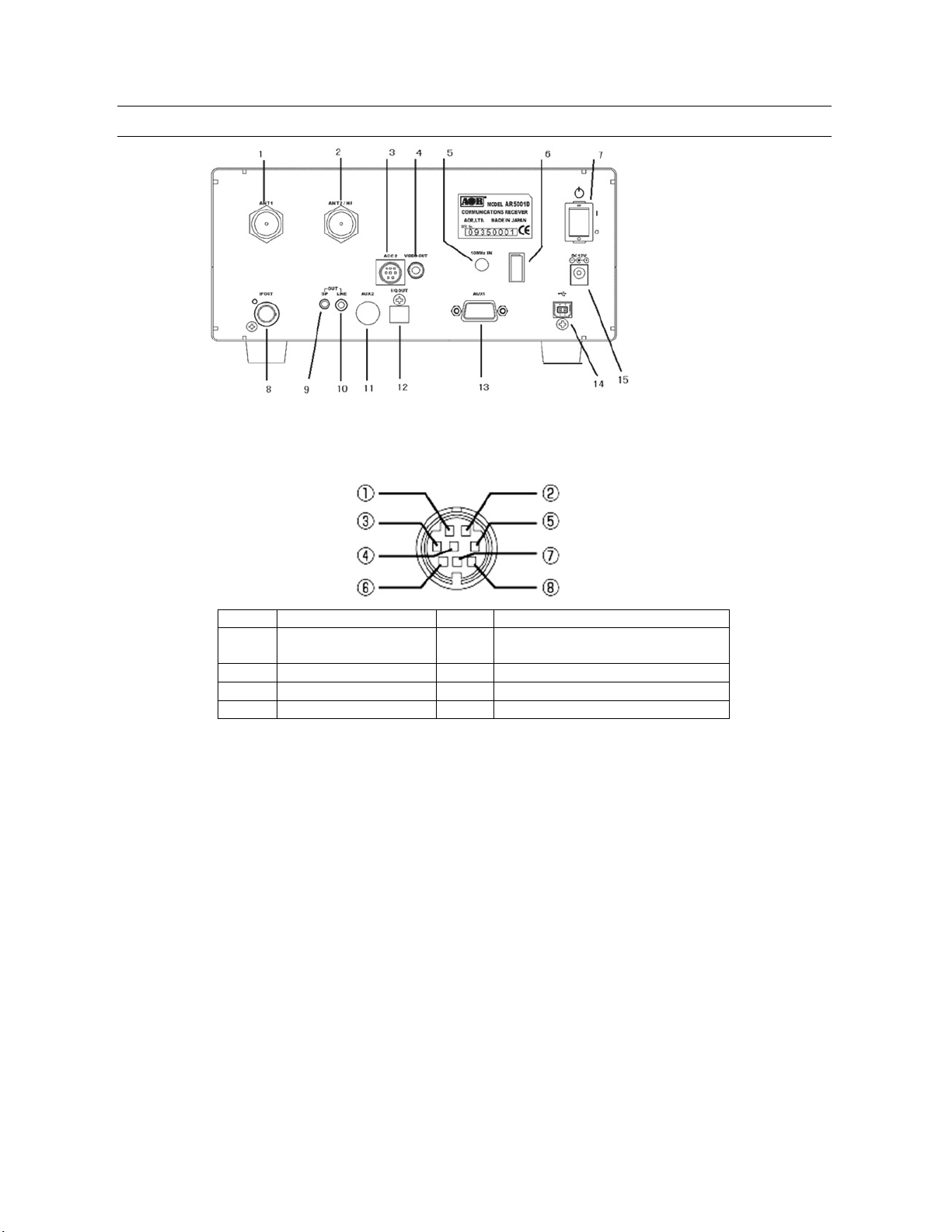
2-2 REAR PANEL
Pin #
Description
Pin #
Description
1 12V DC output
5 Antenna swit ch A
2
No Connection
6
Antenna swit ch B
3
No Connection
7
No connection
4
No Connection
8
Ground
1. Antenna connector 1 (N type) (25MHz~3.15GHz)
2. Antenna connector 2 (N type) (40kHz~3.15GHz)
3. ACC2 (Accessory 2) connector
(50mA max.)
4. Composite video output (RCA type) 75 ohm 1V p-p
5. External 10 MHz reference signal input connector (SMA type) (2 dBm +/- 2dB)
6. Power cable clamp
7. Main power switch
8. 45.05 MHz IF output connector (BNC type)
(A 50 o hm terminator needs to be connec ted while not in use.)
9. External speaker output (3.5 mm mono)
10. Line output connector (3.5 mm stereo, -10 dBm/600 ohm).
(Can b e selected as 12 kHz I/Q output)
11. AUX2 (Auxiliary connector 2) Interface for an opt ional GPS unit
12. I/Q output connector (Optional, USB type B connector)
13. AUX1 (Auxiliary connector 1) D-Sub 9 Male, for expanded function (optional)
or RS-232C serial control interface
14. USB (2.0) connector (USB type B connector)
15. 12 VDC po wer input (2 A)
13

2-3 LCD DISPLAY
Icon Function
GPS status (optional)
SLEEP
Sleep function activated
B Busy (Squelch open)
AUTO
Auto receive mode
PAUSE
Scan/Search pause
DCS
DCS (Digital Code Squelch) function activated
= AGC off
Freq uency display mod e
Band scope mode
F Function switch
O Dual channel receive (offset mode)
D Dual band receive (HF and V/U)
Lit: Frequency reference 0.01 ppm
Blink: Frequency refe rence 0.1 ppm
Not lit: No GPS installe d
Key lock/Remote control mode
ALARM Alarm function activated
REC SD card status (REC: Recording, SD: Card detected)
PRIO Priority function activated
ANT Antenna input
-120. 0dB S reading / Antenna input level (i n dBm when amplifier is of f.)
ATT Attenuation level
AMP RF amplifier on
ST: 009.000k Frequency step
L-BANK Bank link
VFO Operation mode (VFO, MEM, SCAN, S.SCAN, SRCH, CYBER)
VCS Voice scan mode
PASS Frequency pass
AS-M Auto memory store function activated
TONE CTCSS function activated
STEP-ADJ Step adjust function activated
145.000000 Receiving frequency
BW 15k IF bandwidth
FM Receive mode
VA VFO, channel number
SPAN FFT display span (0.4 ~ 10.0 MHz)
Audio balance (displayed in o ffset mode, dual band receive mode)
14

2-4 KEYPAD
Keypad conventions
Most keys have secondary functions; their functions are printed on the panel. However, due to the
restric tion of available size, not all functions can be shown on the keypad printing.
For the secondary functions of the AR5001D, they are indicated with white characters above each
key. To access the secondary funct ion, press the [FUNC] key, and then press the respective key.
2-4-1 FRONT PANEL KEYS
POWER
This k ey is located on the upper left corner of the front panel.
Press this key to power on the AR5001D. To power off t he AR5 001D, press and hold this key for
two seconds.
FUNC
The functio n key is used to select secondary functions on the keypad. When pressed, “F” in reverse
contrast appears on the top left corner of the LCD. The first function of the keys are printed on their
faces; the secondary functions are printed in white directly above the corresponding key.
To cancel the “FUNC”, press this key again.
Press and hold the [FUNC] key for two seconds to go into the FFT display mode. To cancel the FFT
display mode, press the [FUNC] key again.
SRCH - SR. MODE
Press this key to go into search mode and initiate SEARCH. If the receiver stops on an unwanted busy
channel during search, it can be resumed using the [UP] key or [DOWN] key or by rotating the main
dial.
To cancel search, press the [SRCH] key again or press the [VFO] key.
Press the [FUNC] key, and press the [SRCH] key to activate a sub menu where bank link, pause,
delay, voice search, and auto-store function can be configured.
SCAN – SC. MODE
Press this key to go into memory recall mode.
The bank number can be selected using the sub dial, channel number using the main dial and four
digit bank/channel number using the numeric key switch.
15

Press the [SCAN] key again to initiate SCAN. If the receiver stops on an unwanted busy channel during
scan, it can be resumed using the [UP] key or [DOWN] key or by rotating the main dial.
To cancel scan, press the [SCAN] key again or press the [VFO] key.
Press the [FUNC] key, and press the [SCAN] key to activate a sub menu where bank link, pause,
delay, level squelch, and voice squelch function can be configured.
PRIO – PR. SET
Press the [PRIO] key to activate/deactivate the priority function.
“PRIO” appears on the center top of the LCD when priority frequency is currently active (busy).
Press the [FUNC] key, and press the [PRIO] key to select the priority channel followed by the interval
of sampling.
VFO – V. MODE / 2F. BAND
Press this key to select VFO mode. The AR5001D has 5 VFOs (VFO-A through VFO-E) and the
selected VFO is identified by “VA”, “VB”, “VC”, “VD”, and “VE” icons on the right bottom of the LCD.
Press the [FUNC] key, and press the [VFO] key to access the VFO search menu where Delay, Voice
squelch and Mode squelch can be configured.
Press the [FUNC] key, then press and hold the [VFO] key for two seconds to activate/deactivate the
dual band receive function.
1 – SR. PROG
Figure ONE for the numeric input of frequencies, bank, channel numbers, etc.
Press the [FUNC] key, and press the [1] key to activate the Search Program menu where bank number,
lower frequency limit, upper frequency limit, receive mode, and text tag can be programmed.
2 – K. LOCK
Figure TWO for the numeric input of frequencies, bank, channel numb ers, etc.
Press the [FUNC] key, and pr ess the [2] key to activate the Key lock function. While activated, all front
panel keys except the [FUNC] key, and [POWER] key are disabled to prevent accidental misoperation of
the receiver. However, the volume and squelch controls remain operative.
16

3 – IF BW
Figure THREE for the numeric input of frequencies, bank, channel numbers, etc.
Press the [FUNC] key, and press the [3] key to activate the IF bandwidth menu. In normal operation,
“AUTO” will be displayed on the LCD and the IF bandwidth will be automatically selected acco rding to the
band plan. To change the bandwidth manually, rotate the sub dial to select the desired bandwidth. To
accept the new bandwidth, press the [MHz] key.
4 – S. SCAN
Figure FOUR for the numeric input of frequencies, bank, channel numbers, etc.
Press the [FUNC] key, and press the [4] key to ac tivate SELECT SCAN. Select scan enables you to ‘tag’
memory channels to make a temporary lis t of up to 100 channels in the same memory bank for scanning
in a separate list called SELECT SCAN LIST.
5 – 2F. OFFSET
Figure FIVE for the numeric input of frequencies, bank , channe l numbers, etc.
Press the [FUNC] key, and press the [5] key for two seconds to activate/deactivate the dual frequency
receive function in offset mode.
6 - RF. GAIN
Figure SIX for the numeric input of frequencies, bank, channel numbers, etc.
Press the [FUNC] key, and pr ess the [6] key to activate the manual RF gain control. To change the RF
gain manually, rotate the squelch knob. To cancel the manua l RF gain control, repeat the above steps.
Note: The manual RF gain control is not available while the receiver is in AGC mode.
7 - CLOCK
Figure SEVEN for the numeric input of frequencies, bank, channel numbers, etc.
Press the [FUNC] key, and press the [7] key to display the current time.
Rotating the sub dial allows you to select between the two clocks.
To set the clock, press the [FUNC] key and then press and hold the [7] key for two seconds.
On the screen, you can select 12H/24H, set the date and time us ing the sub dial.
Press the [MHz] key to confirm entry.
17

8 - AL ARM
Figure EIGHT for the numer ic input of frequencies, bank, channel numbers, etc.
Press the [FUNC] key, and press the [8] key to activate the alarm function which automatically turns on
the receiver at the preprogrammed time or sound a beep.
9 - SLEEP
Figure NINE for the numeric input of frequencies, bank, cha nnel numbers, etc.
Press the [FUNC] key, and press the [9] key to activate the sleep func tion to turn the receiver off
automatically at the preprogrammed time.
0 - OPTION
Figure ZERO for the numeric input of frequencies, bank, channel numbers, etc.
Press the [FUNC] key, and press the [0] key to activate the option menu.
. - DELETE
Use during the MHz frequency input to separate the MHz from the rest of the entry of kHz and Hz.
For example, the entry of 88.300000 MHz would be [8][8][.][3] [MHz].
Note: Fre quencies below 3.0 MHz (3000 kHz) are always displayed as kHz regardless of input format.
In memory mode, press the [FUNC] key, and press the [.] to display the memory channel to be deleted.
Press the [FUNC] key, and then press and hold the [.] key for two seconds to activate the delete menu.
kHz – CONFIG/SD
The [kHz] key is used to accept frequency input from the numeric keypad in kHz format.
For example, entering of 954 kHz, press [9][5][4][kHz]. The LCD will disp lay 954.000 kHz.
Note: Entering a decimal [.] before the number will result a preceding zero to be added automatically.
Press the [FUNC] key, and press the [kHz] key to activate the configuration menu.
Press the [kHz] while an SD memory card is inserted to act ivate the audio playback func tion.
Usin g the [UP] key or [DOWN] key to select the recorded file, press the [MHz] key to playback audio. To
stop playback, press the [CLR] key.
18

Press and hold the [kHz] for two seconds while an SD memory card is inserted to start recording audio.
To stop recording, press the [CLR] key.
MODE – AF. SET
Press this key to select the receive mode. Rotate the sub dial to select the desired received mode, and
press the [MHz] key to confirm the selection.
To select AUTOMODE, press and hold the [MODE] key for two seconds. The AR5001D will
automatically select the receive mode, IF bandwidth, and frequency step from the pre-programmed band
plan. When in auto mode, “AUTO” is displayed above the frequenc y on the LCD.
Press the [FUNC] key, and press the [MODE] key to activate the AF. SET (Audio frequency setup) menu
to configure the LPF (Low Pass Filter), HPF (High Pass Filter), De-emphasis, and CW pitch frequency.
STEP - AGC
Press this key to select the frequency step size for tuning the receiver. If “ AUTO ” is displayed on the LCD,
the frequency step will automatically be determined from the receiver’s bandplan.
To change the frequency step, press the [STEP] key. Rotate the sub dial to select the desired frequency
step, and then press the [MHz] key.
Press the [FUNC] key, and then press the [STEP] key to activate the AGC (Automatic Gain Control)
menu. In this menu, “FAST”, “MIDDLE”, “SLOW”, or “OFF” can be selected. Usually, FAST is used to
receive CW, MEDIUM for AM and FM, and SLOW for SSB mode. However, this option cannot be
config ured in the FM mode.
When AGC is set to OFF, two horizontal bars are displayed on the LCD above the “kHz” or “MHz” icon.
PASS – S. SET
This k ey is used to PASS (skip over) unwanted active frequencies in search mode and scan mode.
In search mode, the unwanted frequencies are stored in the PASS LIST where they may be added to,
deleted, or edited.
In scan mode, the memory is locked out and is skipped. While in scan mode or memory channel read
mode, press the [FUNC] key, and then press the [PASS] key. This will add the displayed channel to the
SELECT SCAN list. This is a special temporary notepad memory bank.
19

The [PASS] key is also used to selec t on/off of certain options such as step adjust and select defaults in
other menus.
MHz – ENT/TEXT
This k ey has three functions.
MHz – This key is used to enter frequencies as MHz in VFO mode.
For example, to set a frequency of 88.300 MHz, enter the key sequence [8][8][.][3][MHz].
There is no need to add the remaining zeros to the right once the [MHz] key is pressed.
ENT – This key is used to confirm entry in most menus.
If this key is held f or two seconds in VFO mode, the AR5001D goes in to memory write mode.
Use the main dial knob to select the desired memory channel number, sub dial for memory bank to
store into memory. Press this key again to enter a memory text screen of up to 12 characters to be
added to each memory channel.
TEXT – Press the [FUNC] key, and then press the [MHz] key to display the memory texts.
ATT – ANT
This key is used to selec t the RF attenuator menu. The menu has a selection of AUTO, AMP 0 dB, 0 dB,
-10 dB, or -20 dB.
Press the [FUNC] key, and then press the [ATT] key to activate the antenna input selection menu.
The menu has a selection of 1, 2, 3, 4, and PRG. To use the antenna 3 and 4, an optional AS5001
antenna relay will be required.
CLR
The CLEAR key is used to cancel frequency entry during programming or exit from a menu.
UP - MAIN
In VFO mode, press this key to change the displayed frequency to be incremented in an upward direction
by one step.
In VFO mode, press and hold this key for two seconds to activate frequency search.
In memory read mode, press and hold this key for two seconds to activate scan.
In memory text input mode, this key will move the cursor to the next space.
In dual band/dual frequency mode, press the [FUNC] key, and then press and hold this key to activate
the audio level balance adjust menu for t he main band.
20

DOWN - SUB
In VFO mode, press this key to change the displayed frequency to be incremented in a downward
direction by one step.
In VFO mode, press and hold this key for two seconds to activate frequency search.
In memo ry read mode, press and hold this key for two seconds to activate scan.
In memo ry text input mode, this key will move the cursor to the next space.
In dual band/dual frequency mode, press the [FUNC] key, and then press and hold this key to activate
the audio level balance adjust menu for the sub band.
3 GETTING STARTED
3-1 MAKING THE AR5001D READY FOR OPERATION
3-1-1 CONNECT THE ANTENNA
There are two N antenna connectors on the rear pa nel:
ANT 1 for frequencies between 25MHz and 3.15GHz.
ANT 2 for frequencies between 40kHz and 3.15GHz.
3-1-2 CONNECT POWER
Connect the power to the DC power jack on the rear panel of the AR5001D.
A supplied AC power adapter or a regulated DC power supply (10.7 ~ 16.0V with capacity 2A) may be
used.
Do not connect to a 24V system.
3-2 SWITCHING ON FOR THE FIRST TIME
Turn on the power switch on the rear panel of the AR5001D. T his is the main power switch.
The clock will be displayed on the LCD.
21

Press the power switch on the front panel of the AR5001D.
As you press the power switch, a ‘click’ will be heard.
Please be careful NOT to switch on the receiver with an earphone connected because there may be an
audible click when the unit is switched on and the volume may be accidentally set too high.
Opening screen
(Note: The version number may vary.)
After the opening screen appears on the LCD, the main screen will then be displayed.
Main screen (sample)
To power off the AR5001D, press and hold the power switch on the front panel for two seconds.
After “AR5001D SHUT DOWN” message is displayed, the receiver will automatically power off.
22

3-3 VOLUME CONTROL
To change the volume (audio) level, rotate the volume control (AF gain) clockwise to increase, and
counterclockwise to decrease .
The audio level bar will be indicated on the LCD.
3-4 SQUELCH CONTROL
To change the squelch level, rotate the squelch control clockwise to increase, and counterclockwise to
decrease. The squelch level will be indicated on the LCD.
After setting the squelch level, the LCD will return to original display.
While squelch opens, “B” (busy) will appear in reverse contrast on the top left of the LCD.
3-5 VFO SELECTION
The AR5001D has five (5) VFOs identified as “VA” through “VE” on the right bottom of the LCD.
The term VFO historically means ‘Variable Frequency Oscillator’ and today refers to a tunable data
storage which contains frequency, step, step-adjust, attenuato r etc. Pressing the [VFO] key each time
will select the one VFO out of five.
23

Each VFO has a specific function under certain configurations.
VFO-B --- Used for manual search between VFO-A frequency to VFO-B frequency
VFO-C --- Used to transfer frequency from the memory channel
VFO-D --- Used to transfer frequency from the search channel
VFO-E --- Used to receive frequency below 25 MHz while in dual frequency receive mode
The AR5001D has an auto mode setting, there fore, in most cases a proper receive mode and frequency
steps are automa tically selected.
3-5-1 TUNING FREQUENCY
3-5-1-1 ENTERING A FREQUENCY USING THE NUMERIC KEYPAD
While in VFO mode, enter the required frequency using MHz format followed by the [MHz] key.
(Example) Frequenc y entry of 81.3 MHz
Press the [8] key. Press the [1] key. Press the [.] key. Press the [3] key. Press the [MHz] key.
(Example) Frequenc y entry of 1134 kHz (1.134 MHz)
Press the [1] key. Press the [1] key. Press the [3] key. Press the [4] key. Press the [kHz] key.
Aborting frequency input
If you do not wish to complete the frequency data input, press the [CLR] key before completing the
input sequence with the [MHz] key.
Correcting frequency input
Press the [UP] key to delete the entry from the rig ht hand side.
24

3-5-1-2 CHANGING FREQUENCY USING THE MAIN DIAL
In VFO mode, the active VFO frequency may be ‘tuned’ in using the main dial which is mounted on
the right side of the front panel. Rotate the dial ‘clockwise’ to increase frequency o r turn
'counterclockwise’ to decrease frequency.
3-5-1-3 CHANGING FREQUENCY USING [UP] KEY OR [DOWN] KEY
The [UP] and [DOWN] keys provide a convenient method to change the frequency.
The speed the receiver steps up or down depends on the step size which is set to default to auto.
In auto mode, step size, receiver mode etc. are taken from the factory pre-programmed band plan but
may be overridden at any time.
Press the [UP] key to tune the receiver upward in whic hever step size is se lected, use the [DOWN] key
to tune the receiver downward in frequency.
3-6 RECEIVE MODE
Due to the necessities of signal bandwidth, channel occupancy and transmission effic iency, different
receive modes are used by various services. The tuning step and receive mode are allocated by
departments of Governments following international discussions so they are not consistent throughout the
world. For this reason, it is necessary to change receive mode in order to monitor various transmissions.
For your convenience, receive mode and tuning step size have been pre-programmed into the AR5001D
auto mode band plan data at the factory to simplify the operations of the receiver, especially while you
familiarize yourself with the functions. If needed, the defaults may be manually overridden at anytime
so that you may select an alternative receive mode and tuning step on any frequency.
AM – Amplitude Modulation
Used by broadcas t services throughout the world on long wave, medium wave and short wave.
AM is also used by VHF airband, UHF military airband.
SAM – Synchronous AM
Helps to listen to SW (Shortwave) AM broadcast stations with fading signals.
FM – There are two common types of FM (Frequency Modulation):
NFM – Narrow Band Frequency Modulation
Provides high quality communication for relatively short distance operation.
FM uses a greater frequency bandwidth than other modes.
25

NFM is the most common mode used above 30 MHz with the exception of the airbands. NFM is
widely used on the VHF bands: VHF marine band, 2m amateur band, 70 cm amateur band, PMR
(Private Mobile Radio) and utilities.
In the absence of a signal, the background white noise may appear quite loud. For easier listening,
the squelch control should be rotated clockwise until the background noise disappears; this should
be carried out while no signal is present. The point at which the background noise is cancelled is
known as the threshold point. Do not advance the squelch control more than necessary or the
receiver will appear to be desensitized and weaker signals will be missed.
WFM – Wide Band Frequency Modulation
Used by VHF and UHF broadcast stations as excellent audio quality.
This is available due to the relatively wide frequency bandwidth employed.
Used only for local services such as VHF band stereo channels.
LSB – Lower Side Band / A form of SSB (Single Side Band).
Not intended for commercial use but is extensively used by Radio Amateurs on frequencies below 10
MHz. This assists in the separation of Commercial and Amateur users on traditionally shared bands and
prevents them from speaking to each other.
SSB is a very efficient method of transmission as the unwanted second sideband and carrier have
been removed. This allows the full transmitter power to be employed in carrying useful information
within the wanted sideband. As a result, greater dis tances are possible on SSB and a smaller
frequency bandwidth is required than with most other modes.
USB – Upper Side Band
The same comments apply as for LSB. By conventio n, Radio amateurs also use USB above 10 MHz.
ISB – Independent Side Band
Similar to SSB, however, 2 independent SSB signals are transmitted on the same frequency.
Decoded signals can be heard separately from the headphone jack on the front panel.
CW - Continuous Wave
Also referred as Carrier Wave or Morse Code.
Commonly used on the short wave bands by ra dio amateurs toward the lower end of each band
allocation. Some commercial use is still made by shipping etc although its use is being phased out due to
the introduction of automated stations.
26

AIQ – Analog IQ for DRM
New digital communication format for SW (Shortwave) broadcast.
Proper software and external hardware are required to decode DRM (not included).
3-6-1 AUTO MODE SELECTION
When in auto mode, the receive mode and tuning step size are automatically selected for you by the
AR5001D microprocessor.
To activate auto mode or reconfirm its selection while in VFO mode, press and hold the [MODE] key for
two seconds. “AUTO” will appears above the frequency portion of the LCD.
Note: Auto-mode is cancelled as soon as the receive mode, tuning step or oth er related data are
changed. Reme mber that auto-STEP and auto-MODE are linked, reselect AUTO MODE if either have
been adjusted and you require the auto band plan selection.
3-6-2 RECEIVE MODE SELECTION
Any receive mo de may be selected at any frequency within the receiver’s frequency coverage.
To access the receive mode menu, press the [MODE] key.
The following modes are available:
FM stereo, FM, NFM, SFM, WAM, AM, NAM, SAM, USB, LSB, CW, ISB, and AIQ.
Use the sub dial to select the desired mode. To accept the selection, press the [MHz] key.
3-7 CHANGING THE FREQUENCY STEP
The specification for channel oc cupancy, step (s eparation) and mode are decided by and allocated by the
Departments of Governments following international discussions.
The allocation of frequency bands are not the same all over the world and channel separation (step)
varies from band to band. As an example, the channel separation (step) for the MW (medium wave) band
27

in the U.S.A. is 10 k Hz, and is 9 kHz in Europe and J apan.
For above reasons, it is necessary to change the frequency step size according to the local band plan.
The AR5001D has been pre-programmed at the facto ry with all the band plan data (specific to each market
area) so that the AR5001D will automatically select the appropr iate ste p size and mode for the frequency
chosen. This greatly simplifies operation o f the receiver while you are familiarizing yourself with all the
functions.
The pre-programming of step size may be manually overridden so you may choose alternative settings
at will or when band plans are updated.
If you wish to change the default tuning frequency step, press the [STEP] key. The LCD will dis play the
current frequency step and the blinking “STEP” while waiting for the new parameter. Use the sub dial to
select the desired step.
To accept the displayed tuning step size, press the [MHz] key.
The tuning step size may also be programmed in 1 Hz (via the keypad) so that unusual step sizes other
than those stated are possible. The acceptable step siz e range is less than 1 MHz in 1 Hz steps.
3-8 IF BANDWIDTH
The IF bandwidth selects how SELECTIVE the receiver will be when monitoring signals off air. However,
it is not simply a case of using the narrowest filter at all times; particular modes require differing amounts
28
 Loading...