

Page 1
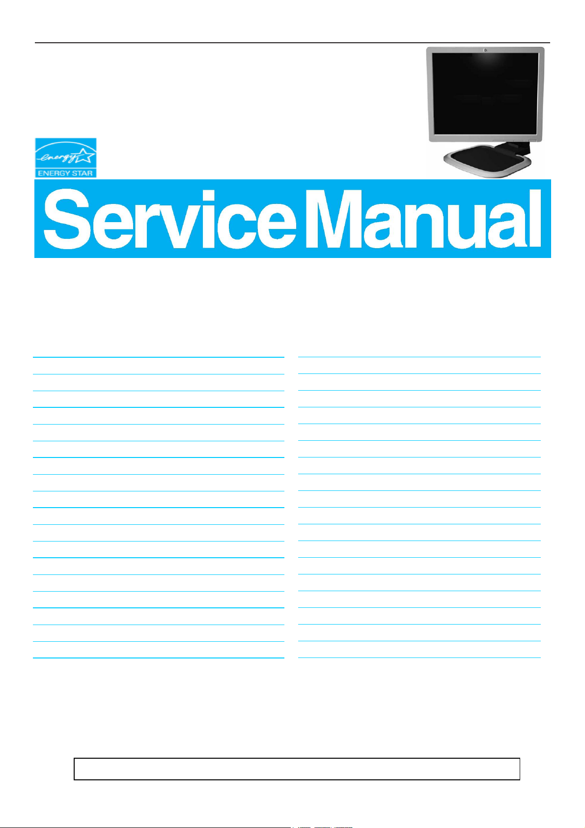
17" LCD Color Monitor HP L1750
Service
Service
Service
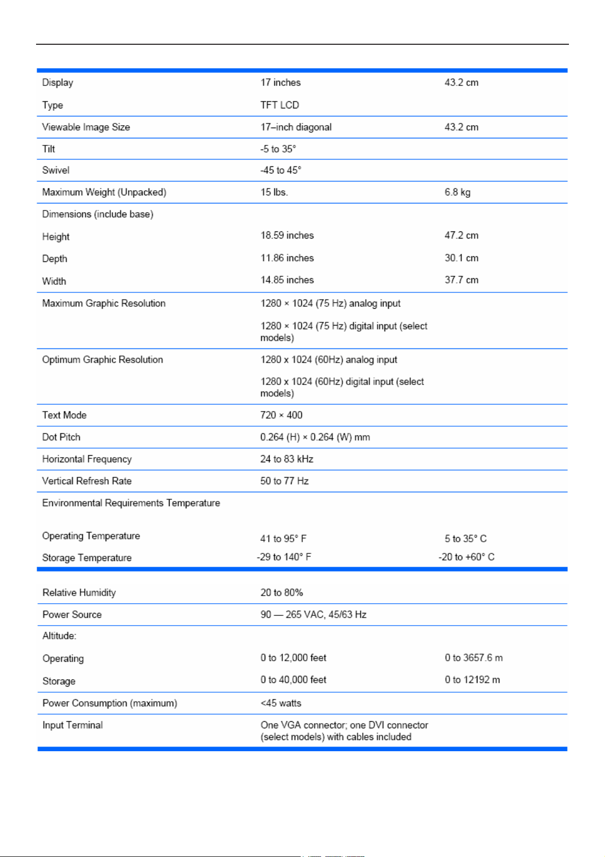
Horizontal Frequency
24- 83 kHz
TABLE OF CONTENTS
Description Page Description Page
Table Of Contents.......……..............................…........1
Revision List.…........................................……......2
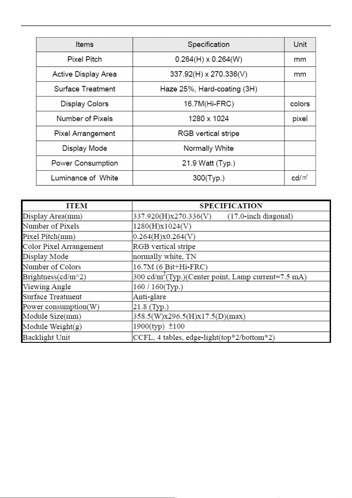
1. Monitor Specification..............................………........4
2. LCD Monitor Description…………………………….......5
3. Operation Instruction…………...............……...........6
3.1. General Instructions...........................…...........6
3.2. Control Button…………….…..............……...............6
3.3 Adjusting the Picture...........................…............7
4. Input/Output Specification............……………............11
4.1. Input Signal Connector............………….................11
4.2. Factory Preset Display Modes......…..................12
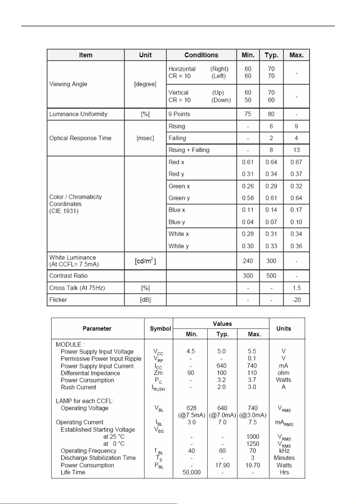
5. Panel Specification.....………………..................13
5.1. General Feature…….....………………..................13
5.2. Optical Characteristics………………………………15
6. Block Diagram……...................…………................18
6.1 Software Flow Chart………………………………...18
6.2.Electrical Block Diagram……………..….......20
7. Schematic……………......................................22
7.1 Main Board....……….......................................22
7.2 Power Board.….……....................................26
7.3 Key Board…………………………………………..30
7.4 USB Board…………………………………………31
8.PCB Layout..…….......................................32
8.1. Main Board………........................................33
8.2. Power Board….......................................34
8.3. Key Board………............….......................36
8.4 USB Board…………………………………………37
9. Maintainability……….......................................39
9.1. Equipments and Tools Requirement..............39
9.2. Trouble Shooting……….............................40
9.2.1 Main Board…………..............................40
9.2.2 Power Board………..............................42
9.2.3 Key Board…………..............................44
10 White-Balance, Luminance adjustment...45
11.Mechanical Instructions……………..…...….......47
12. Monitor Exploded View………………..…....….......53
13. BOM List………………………………..……………54
14. Different Parts List.........…………..........................68
SAFETY NOTICE
ANY PERSON ATTEMPTING TO SERVICE THIS CHASSIS MUST FAMILIARIZE HIMSELF WITH THE CHASSIS
AND BE AWARE OF THE NECESSARY SAFETY PRECAUTIONS TO BE USED WHEN SERVICING ELECTRONIC
EQUIPMENT CONTAINING HIGH VOLTAGES.
CAUTION: USE A SEPARATE ISOLATION TRANSFOMER FOR THIS UNIT WHEN SERVICING
1
Page 2
17" LCD Color Monitor HP L1750
Revision List
Version Date Revision History TPV Model Name
A00 Aug.-06-2007 Initial release T77AMMDKHNHPQNE
A01 Aug.-10-2007 Add TPVDW Model in Item 14 T77GMMDKHNHPQNE
A02 Sep.-14-2007 Add TPVDW Model in Item 14
A03 Sep.-21-2007 Add TPVDW Model in Item 14
A04 Oct.-10-2007 Add TPVDW Model in Item 14 T77AMMDTHNHPQNE
A05 Oct.-16-2007 Add TPVDW Model in Item 14
A06 Oct.-22-2007 Add TPVDW Model in Item 14 T77GMMDDHNHPQNE
A07 Nov.-01-2007 Add TPVDW Model in Item 14
A08 Nov.-06-2007 Add TPVDW Model in Item 14 T77GMMDQHNHPQNE
A09 Nov.-16-2007 Add TPVDW Model in Item 14
A10 Vec.-03-2007 Add TPVDW Model in Item 14 T77AMMDLHNHPQNE
T77GMMDTHNHPQNE
T77CMMDKHNHPQNE
T77CMMDLHNHPQNE
T77GMMDLHNHPQNE
T77CMMDTHNHPQNE
T77AMMDBHNHPQNE
T77CMMDBHNHPQNE
T77CMMDQHNHPQNE
T77GMMDBHNHPQNE
T77SMMDKHNHPQNE
T77SMMDQHNHPQNE
T77SMMDTHNHPQNE
LM170E03-TLL2 LPL
LM170E03-TLG2/TLG4
CLAA170EA07P 040
Add Second Panel list in Item 5
A11 Dec.-12-2007
Add TPVDW Model in Item 14
A12 Jan.-22-2008 Update Power Board in Item 7 715G2655 2 2
A13 Jul.-01-2008 Add Second Panel list in Item 5 CPT EA07P 8H4U/8H4V 8J4U/8J4V+MST
A14 Nov.-05-2008 Add TPVDW Model in Item 14
M170EG01 VD00 AUO
LTM170EU-L31 QBC(
LTM170EU-L31 8TM
M170EG01 VD0B SZ
T77SMMDKHNHPQ1E
T77CMMDDHNHPQNE
T77SMMDLHNHPQNE
T78CMMDKHNHP2NE
T77SMMDBHNHPQ1E
T77GMMDBHNHPQ1E
T77GMMDKHNHPQ1E
2
T77SMMDDHNHPQNE
T77CMMDBHNHPQ6E
T77CMMDKHNHPQ6E
T77CMMDBHNHPQ1E
Page 3
17" LCD Color Monitor HP L1750
T77CMMDKHNHPQ1E
T77GMMDDHNHPQ1E
T77GMMDTHNHPQ1E
T77GMMDLHNHPQ1E
T77CMMDDHNHPQ1E
T77AMMDBHNHPQCE
T77GMMDBHNHPQ6E
T77CMMDTHNHPQ6E
T77GMMDKHNHPQCE
T77GMMDKHNHPQ6E
T77SMMDDHNHPQCE
T77SMMDBHNHPQCE
T77SMMDKHNHPQCE
T78CMMDKHNHP21E
3
Page 4
17" LCD Color Monitor HP L1750
1. Monitor Specification
4
Page 5

17" LCD Color Monitor HP L1750
(
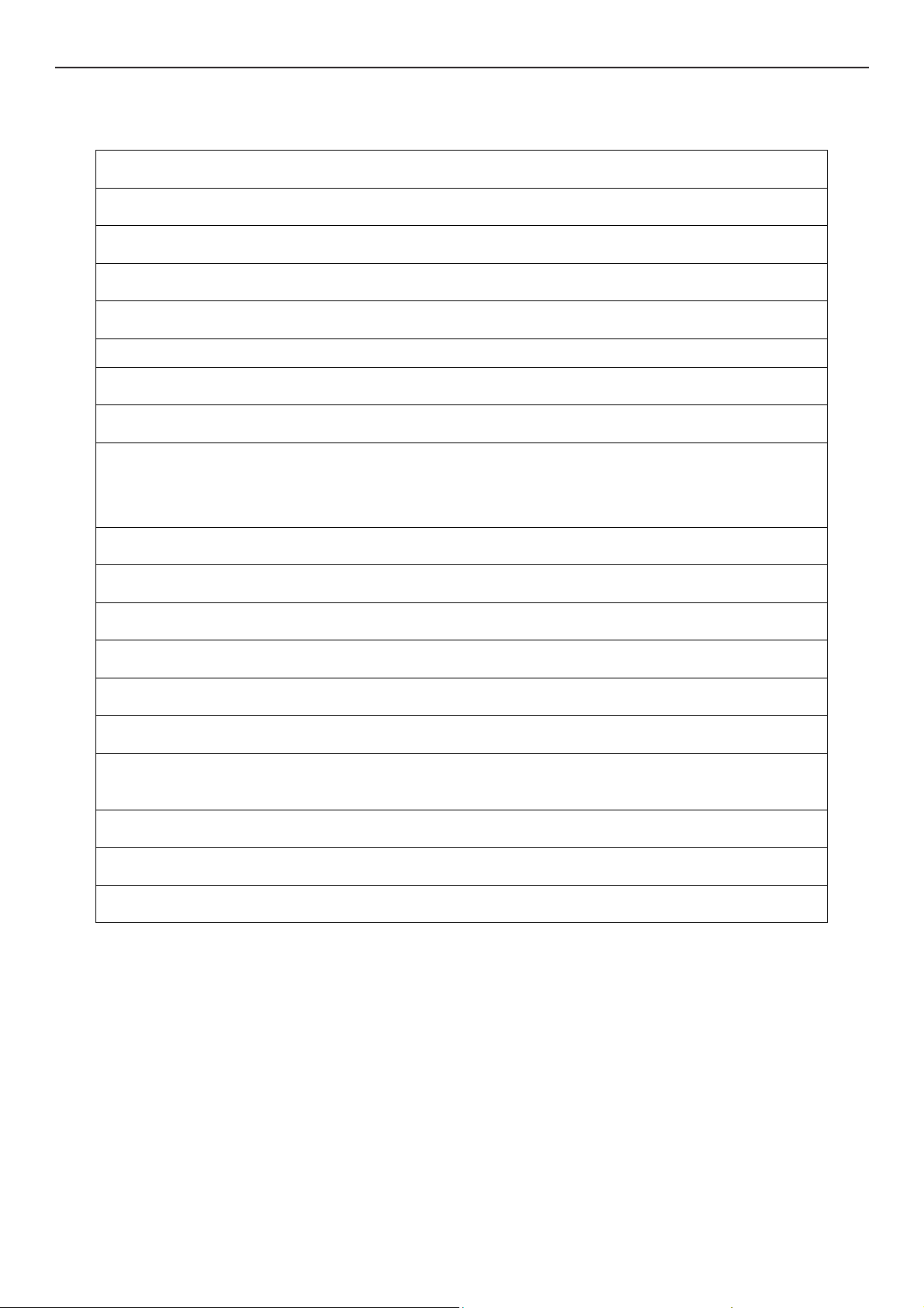
2. LCD Monitor Description
The LCD Monitor will contain main board, power board, a key board which house the flat panel control logic, brightness
control logic and DDC.
The power board will provide AC to DC Inverter voltage to drive the backlight of panel and the main board chips each
voltage.
Power Board
Include adapter board)
AC-IN
110V-240V
Monitor Block Diagram
CCFT Drive.
Main Board
Keyboard
Flat Panel and
CCFL backlight
RS232 Connector
For white balance
adjustment in
factory mode
Video signal, DDC
HOST Computer
5
Page 6
17" LCD Color Monitor HP L1750
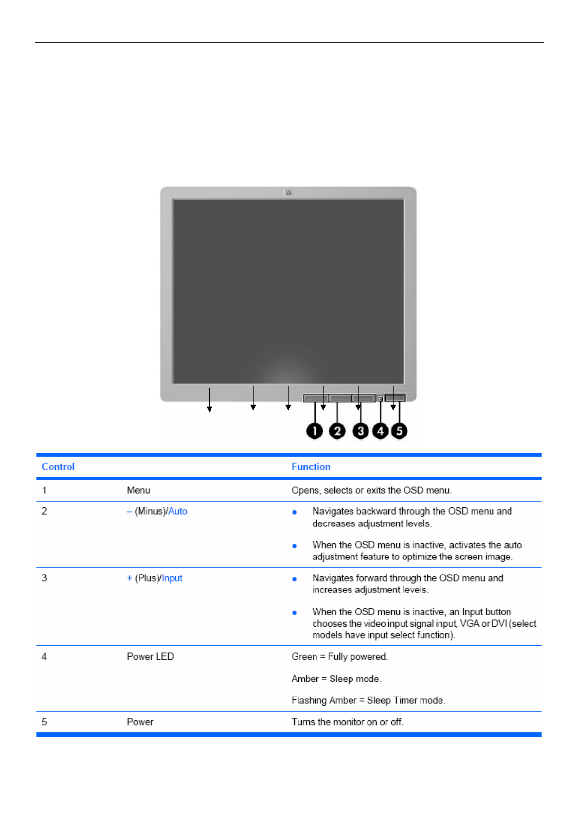
3. Operation Instructions
3.1 General Instructions
Press the power button to turn the monitor on or off. The other control buttons are located at front of the panel. By
changing these settings, the picture can be adjusted to your personal performance.
The power cord should be connected and insert to adaptor.
-
Connect the video cable from the monitor to the computer VGA card.
-
- Press the power button to turn on the monitor, the power indicator will light up to Green.
3.2 Control Button
6
Page 7
17" LCD Color Monitor HP L1750
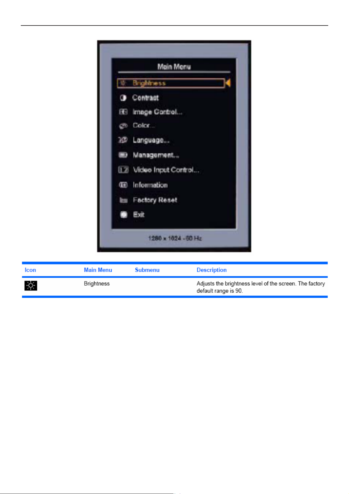
3.3 Adjust the Picture
7
Page 8
17" LCD Color Monitor HP L1750
8
Page 9
17" LCD Color Monitor HP L1750
9
Page 10
17" LCD Color Monitor HP L1750
10
Page 11
17" LCD Color Monitor HP L1750
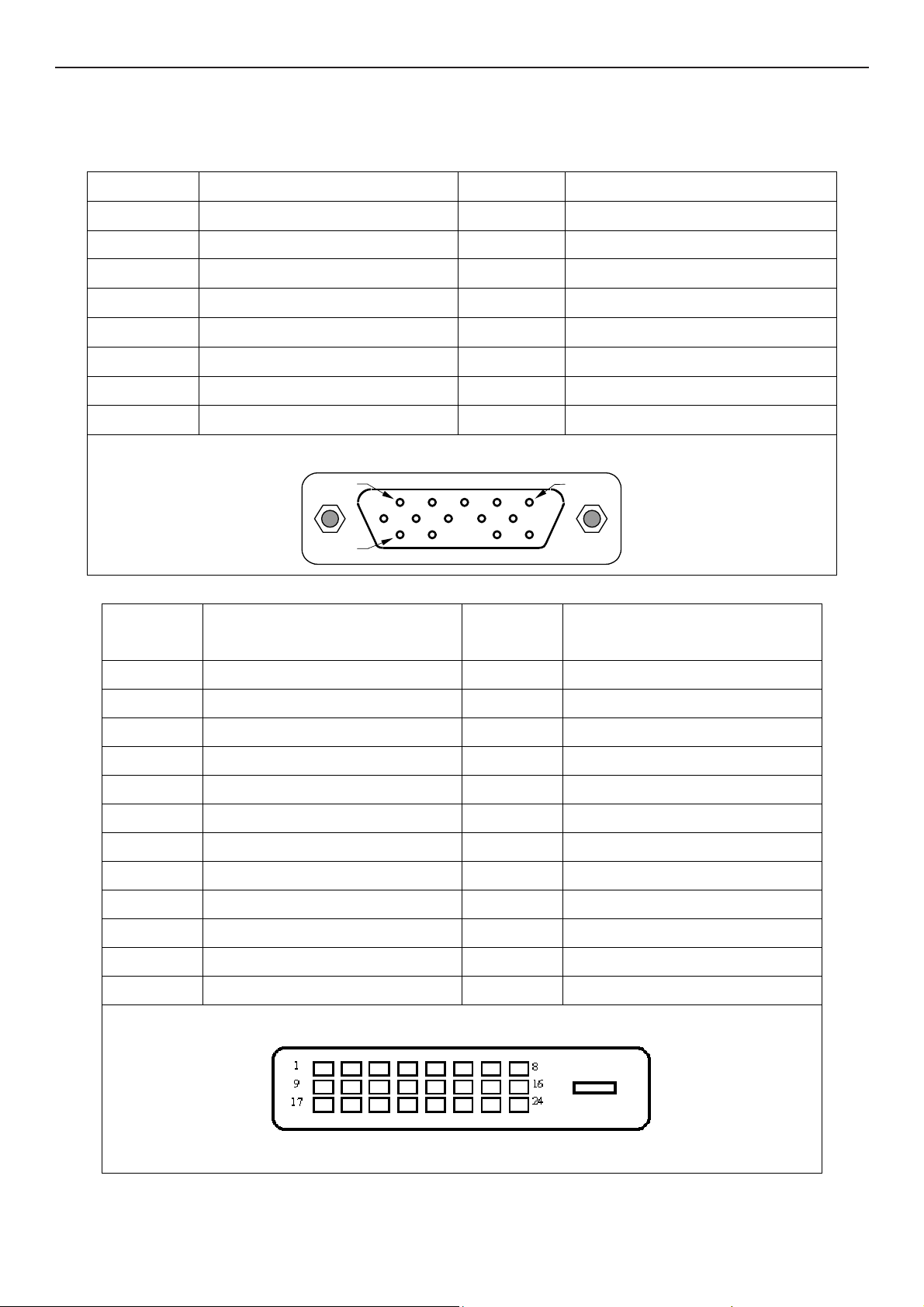
4. Input/Output Specification
4.1 Input Signal Connector
4.1.1 D-SUB connector
Pin Signal Pin Signal
1 Red Video 9 3.3/+5 V (from PC)
2 Green Video 10 Sync Ground
3 Blue Video 11 None
4 None 12 DDC Data
5 Ground (DDC Return) 13 Horizontal Sync
6 Red GND 14 Vertical Sync
7 Green GND 15 DDC Clock
8 Blue GND
4.1.2 DVI-D connector
Pin No.
1 TMDS Data 2- 13 TMDS Data 3+
2 TMDS Data 2+ 14 +5V Power
3 TMDS Data 2/4 Shield 15 Ground(for+5V)
4 TMDS Data 4- 16 Hot Plug Detect
5 TMDS Data 4+ 17 TMDS Data 0-
6 DDC Clock 18 TMDS Data 0+
7 DDC Data 19 TMDS Data 0/5 Shield
PIN 1
PIN 11
Signal Name
VGA connector layout
PIN 5
Pin No.
Signal Name
8 N.C. 20 TMDS Data 5-
9 TMDS Data 1- 21 TMDS Data 5+
10 TMDS Data 1+ 22 TMDS Clock Shield
11 TMDS Data 1/3 Shield 23 TMDS Clock +
12 TMDS Data 3- 24 TMDS Clock -
24 - Pin Color Display Signal Cable
11
Page 12
17" LCD Color Monitor HP L1750
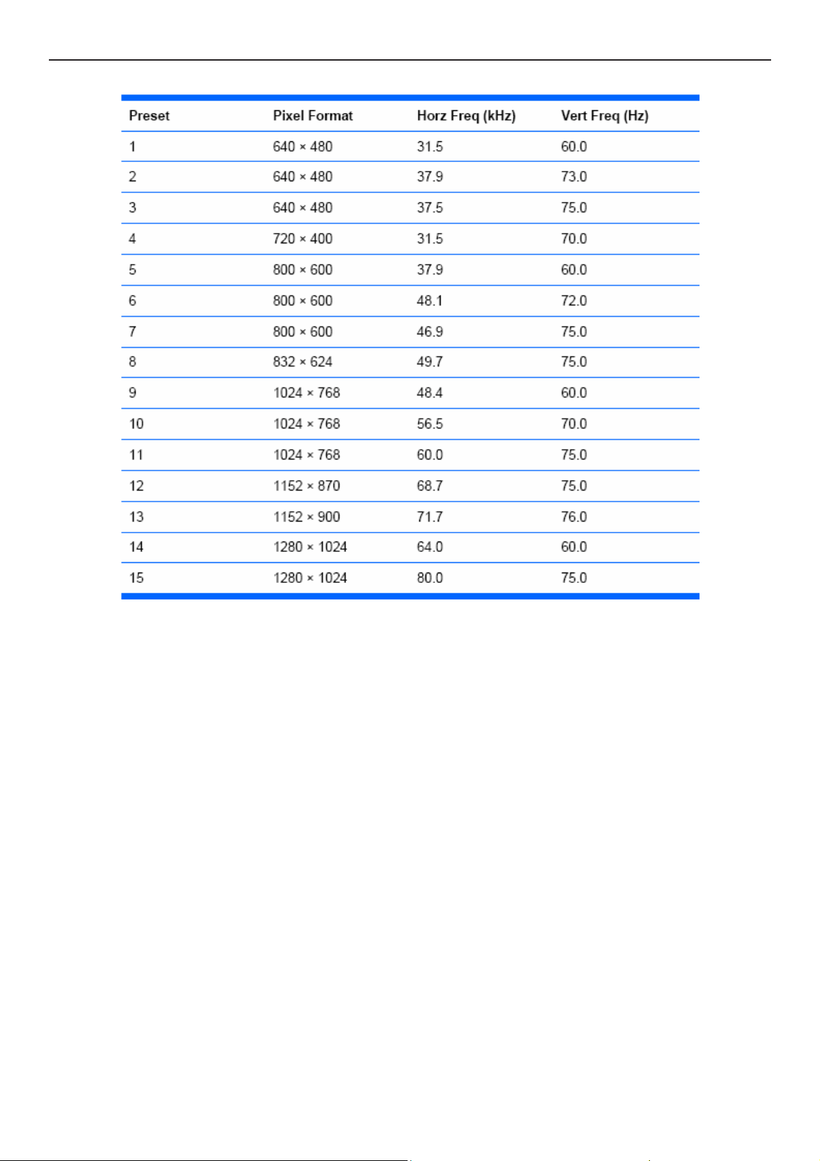
4.2 Factory Preset Display Modes
12
Page 13
17" LCD Color Monitor HP L1750
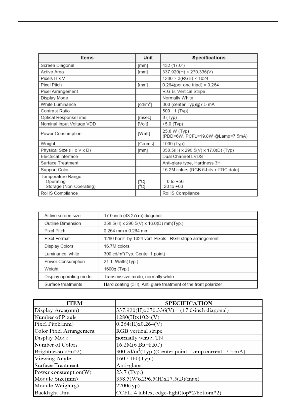
5. Panel Specification
5.1 General Feature
M170EG01 VD00 AUO / M170EG01 VD0B SZ
LM170E03-TLL2 LPL/LM170E03-TLG2/TLG4
CLAA170EA07P 040
13
Page 14
17" LCD Color Monitor HP L1750
LTM170EU-L31 QBC / LTM170EU-L31 8TM
CPT EA07P 8H4U/8H4V 8J4U/8J4V+MST
14
Page 15
17" LCD Color Monitor HP L1750
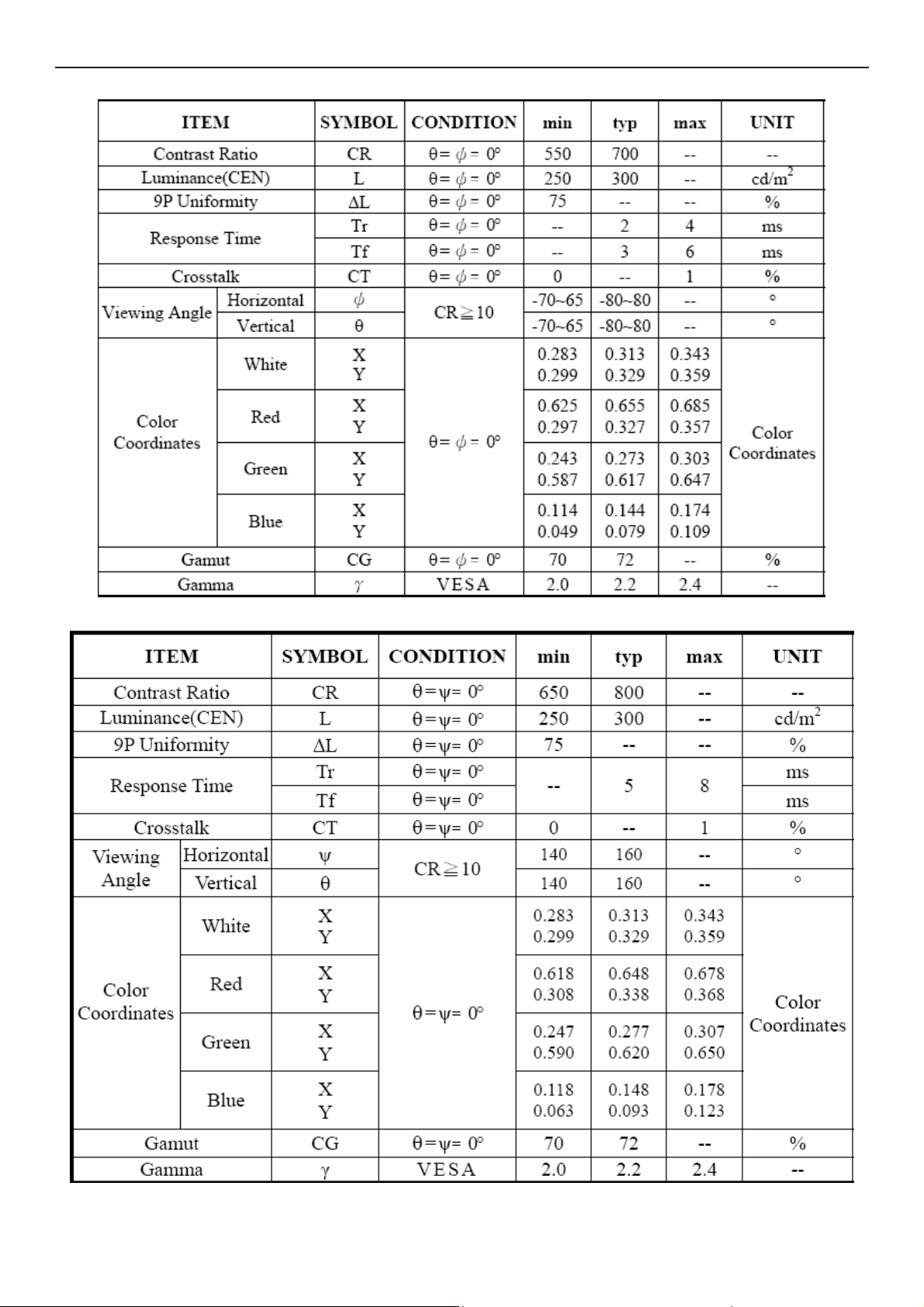
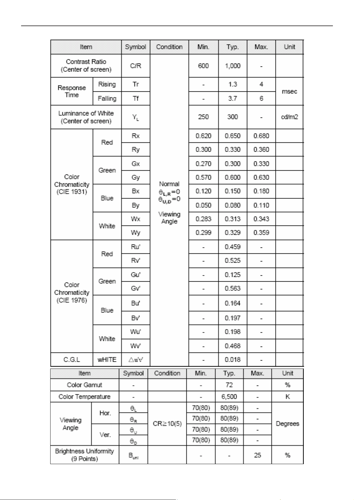
5.2 Optical Characteristics
M170EG01 VD00 AUO / M170EG01 VD0B SZ
LM170E03-TLL2 LPL/LM170E03-TLG2/TLG4
15
Page 16
17" LCD Color Monitor HP L1750
CLAA170EA07P 040
CPT EA07P 8H4U/8H4V 8J4U/8J4V+MST
16
Page 17
17" LCD Color Monitor HP L1750
LTM170EU-L31 QBC / LTM170EU-L31 8TM
17
Page 18
17" LCD Color Monitor HP L1750
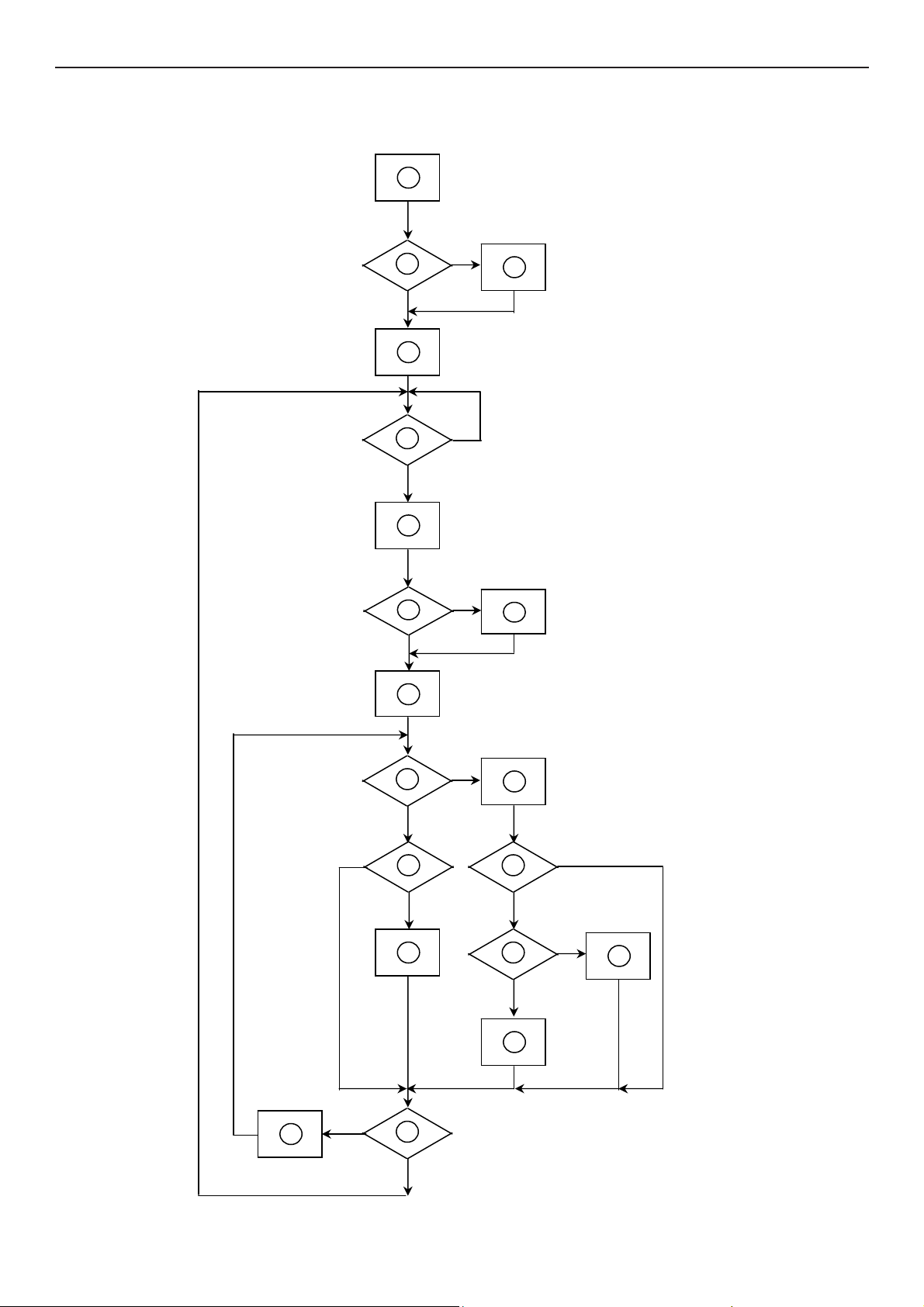
6. Block diagram
6. 1 Software Flow Chart
1
Y
2
N
3
4
5
N
Y
6
N
7
8
Y
9
10
N
11
12
Y
13
N
N
Y
14
15
Y
N
16
Y
17
18
N
19
Y
18
Page 19
17" LCD Color Monitor HP L1750
REMARK:
1) MCU initialize.
2) Is the EEprom blank?
3) Program the EEprom by default values.
4) Get the PWM value of brightness from EEprom.
5) Is the power key pressed?
6) Clear all global flags.
7) Are the AUTO and SELECT keys pressed?
8) Enter factory mode.
9) Save the power key status into EEprom.
Turn on the LED and set it to green color.
Scalar initialize.
10) In standby mode?
11) Update the lifetime of back light.
12) Check the analog port, are they’re any signals coming?
13) Does the scalar send out an interrupt request?
14) Wake up the scalar.
15) Are there any signals coming from analog port?
16) Display "No connection Check Signal Cable" message. And go into standby mode after the message
disappear.
17) Program the scalar to be able to show the coming mode.
18) Process the OSD display.
19) Read the keyboard. Is the power key pressed?
19
Page 20
17" LCD Color Monitor HP L1750
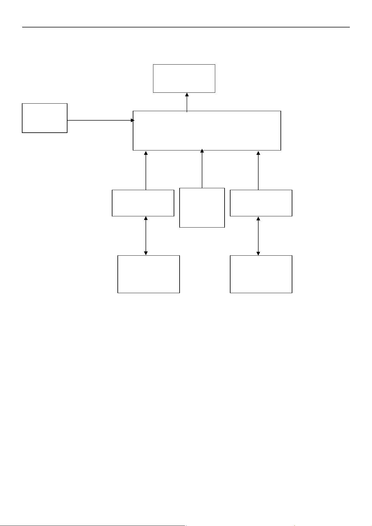
6.2 Electrical Block Diagram
6.2.1 Scalar Board
EEPROM
(U402)
EPR_SDA
EPR SCL
DB15_SDA,
DB15 SCL
Panel Interface
H sync
V sync
D-Sub Connector
RGB
(CN101)
(CN401)
Scalar HUM56AWL-LF
(Include ADC、OSD、MCU)
(U401)
Crystal
X201
14.318Mhz
DVI Connector
RGB
CLK+
CLK-
(CN102)
SDA,
SCL
EEPROM
M24C02
(U101)
EEPROM
M24C02
(U102)
20
Page 21
17" LCD Color Monitor HP L1750
6.2.2 Inverter / Power Board
AC input
EMI filter
Bridge
Rectifier
and Filter
Start Circuit
Transformer
Rectifier
diodes
CN902
12V
PWM
Control IC
Over
Voltage
Protect
Feedback
Circuit
Lamp
LC
Resonance
Transformer
MOSFET
Feedback
Circuit
Over
Voltage
PWM
Control IC
ON/OFF
Control
DIM
5V
ON/OFF
21
Page 22
17" LCD Color Monitor HP L1750
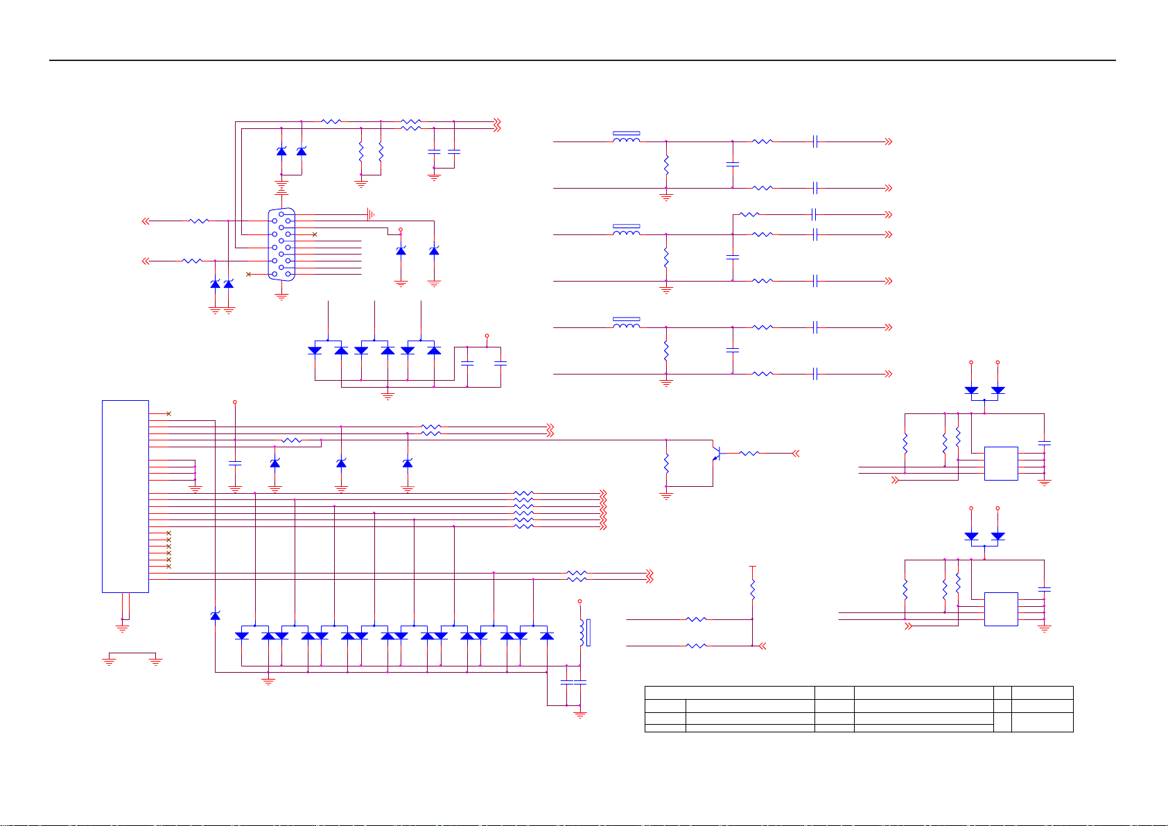
7. Schematic
7.1 Main Board
D107
RLZ5.6B
1
2
2
R102 100R 1/16W
R103 100R 1/16W
C102
22pF
R106
2K2 1/16W
VGA_PLUG
DSUB_5V
ZD103
RLZ5.6B
VGA_G+
3
D103
BAV99
2
1
R119 100R 1/16W
R122 100R 1/16W
D108
RLZ5.6B
3
3
D113
BAV99
2
1
VGA_B+
3
D114
BAV99
D104
BAV99
1
1
ZD104
RLZ5.6B
2
DSUB_H 2
DSUB_V 2
C103
22pF
CMVCC
C118
C112
0.1uF/ 16V
0.1uF/ 16V
DDC2_SCL
DDC2_SDA
R126 10R 1/16W
R127 10R 1/16W
R128 10R 1/16W
R129 10R 1/16W
R130 10R 1/16W
R131 10R 1/16W
3
3
D115
D116
BAV99
BAV99
1
1
2
3
2
VGA_B+
VGA_B-
VGA_G+
VGA_G-
VGA_R+
VGA_R-
DDC2_SCL 2
DDC2_SDA 2
RX0P
RX0N
RX1P
RX1N
RX2P
RX2N
R133 10R 1/16W
R136 10R 1/16W
CMVCC
D117
BAV99
1
C117
0.1uF/ 16V
12
1 2
1 2
1 2
RX0P 2
RX0N 2
RX1P 2
RX1N 2
RX2P 2
RX2N 2
FB104
120OHM
C119
0.1uF/ 16V
FB102
BEAD
FB103
BEAD
FB101
BEAD
RXCP
RXCN
R107
75R 1/16W
R112
75R 1/16W
R116
75R 1/16W
R125
NC
RXCP 2
RXCN 2
DVI_HPD
R138 10K 1/16W
VGA_PLUG
R139 6K8 1/16W
T P V ( Top Victory Electronics Co . , Ltd. )
Date
G2559-1-3-X-2-070719
02 Input
线路图编号
Key Component
R104 100R 1/16W
C104
5pF/50V
R108 100R 1/16W
R109 470R 1/16W
R111 100R 1/16W
C108
5pF/50V
R114 100R 1/16W
R115 100R 1/16W
C111
5pF/50V
R117 100R 1/16W
R124 NC
Q101
NC
VCC3.3
R137
10K 1/16W
DET_CABLE 2
C101
0.047uF
C105
0.047uF
C106
1000pF
C107
0.047uF
C109
0.047uF
C110
0.047uF
C113
0.047uF
HPD_CTRL 2
OEM MODEL Size
TPV MOD EL
PCB NAME
Sheet
DSUB_B+ 2
DSUB_B- 2
DSUB_SOG 2
DSUB_G+ 2
DSUB_G- 2
DSUB_R+ 2
CMVCC
DSUB_R- 2
R121
R135
R118
10K 1/16W
CMVCC
R132
10K 1/16W
R120
4K7 1/16W
DDC1_SCL
DDC1_SDA
DDC_WP2
4K7 1/16W
DDC2_SCL
DDC2_SDA
HP L1750/L1950 B
715G2559-1-3
25Thursday, July 19, 2007
4K7 1/16W
R134
4K7 1/16W
DDC_WP2
of
DSUB_5V
2
3
U101
8
VCC
7
WP
6
SCL
M24C02-WMN6TP
DVI_5V
2
3
U102
8
VCC
7
WP
6
SCL
M24C02-WMN6TP
1
1
Rev
备注
D105
BAV70
0.1uF/ 16V
A0
A1
A2
VSSSDA
D101
BAV70
0.1uF/ 16V
A0
A1
A2
VSSSDA
备注
C114
1
2
3
45
C116
1
2
3
45
-1-3
DDC1_SCL2
DDC1_SDA2
CN102 JACK
VSYN C
SYN C GND
DDC SCL
DDC SDA
1/3shield
2/4shield
0/5shield
clk shield
DAT0+
DAT1+
DAT2+
DAT3+
DAT4+
DAT5+
GND
26
25
GND POWER
HPD
DAT0-
DAT1-
DAT2-
DAT3-
DAT4-
DAT5-
clk+
GND
+5V
clk-
DDC1_SC L
DDC1_SD A
8
15
6
7
14
HOT_PLUG
16
11
3
19
22
18
17
10
9
2
1
13
12
5
4
21
20
23
24
DGND
R110
100R 1/16W
R113
100R 1/16W
ZD105
RLZ5.6B
DVI_HPD
ZD106
RLZ5.6B
DVI_5V
D109
RLZ5.6B
ZD101
RLZ5.6B
C115
0.1uF/ 16V
3
2
15
14
13
12
11
D110
BAV99
R101 0R05 1/16W
ZD102
RLZ5.6B
CN101
10
5
9
4
8
3
7
2
6
1
DB15
17 16
2
R123 10K 1/16W
D106
RLZ5.6B
3
D111
BAV99
1
2
1
2K2 1/16W
DSUB_5V
VGA_R+
3
2
R105
VGA_BVGA_B+
VGA_GVGA_G+
VGA_RVGA_R+
D102
BAV99
1
3
D112
BAV99
22
Page 23
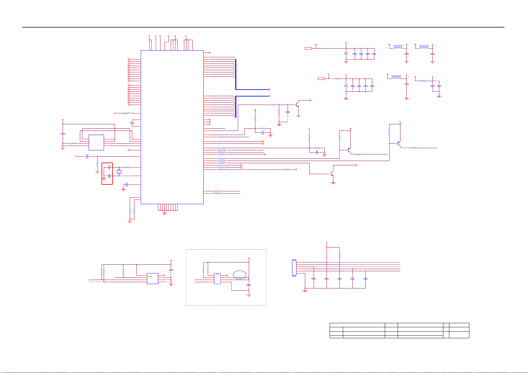
17" LCD Color Monitor HP L1750
VDDC
VDDP
AVDD
VPLL
VMPLL
VCC1. 8
1
10uF/50V
FB205
0R05 1/8W
32
Q205
NC
C202
C209
NC
R209
10K 1/16W
VDDP
+
C203
0.1uF/16V
VDDC
C211
+
0.1uF/ 16V
VCC3. 3
Q203
2N3906S-RTK/PS
R216 56 OH M 1/16W
C204
0.1uF/16V
C212
0.1uF/16V
Volume# 4
C205
0.1uF/ 16V
C214
C213
0.1uF/ 16V
LED_GRN/BLUE
0.1uF/ 16V
8
24
163249
AVDD_PLL
AVDD_MPLL
56
75
VDDP
VDDP
VDDP
AVDD_ADC
14
98
AVDD_DVI
AVDD_DVI
LVDS
GND
GND
GND
GND
GND
GND
GND
GND
2
GND
5
112933
5057767983
51
668234
VDDP
VDDC
VDDC
GPIO_P15/PWM0
PWM2/GPIO_P2 4
PWM1/GPIO_P2 5
GPIO_P00/SAR1
GPIO_P01/SAR2
GPIO_P02/SAR3
PWM0/GPIO_P2 6
GPIO_P16/PWM2
GPIO_P10/ I2C_MCL
GPIO_P11/I2C_MDA
GND
U401
HUM56AWL-LF
VCTRL
VDDC
VDDC
LVA3P
LVA3M
LVACKP
LVACKM
LVA2P
LVA2M
LVA1P
LVA1M
LVA0P
LVA0M
LVB3P
LVB3M
LVBCKP
LVBCKM
LVB2P
LVB2M
LVB1P
LVB1M
LVB0P
LVB0M
NC
NC
NC
GPIO_P23
GPIO_P22
GPIO_P12
RSTN
GPIO_P06
GPIO_P07
GPIO_P13
GPIO_P14
81
PA0
54
PA1
55
PA2
58
PA3
59
PA4
60
PA5
61
62
PA6
PA7
63
PA8
64
PA9
65
PB0
67
PB1
68
PB2
69
PB3
70
PB4
71
PB5
72
PB6
73
PB7
74
PB8
77
PB9
78
36
45
46
EE_WP
41
42
35
R207 100R 1/ 16W
47
85
86
87
88
R213 100R 1/ 16W
R214 100R 1/ 16W
89
R215 100R 1/ 16W
90
R217 4K7 1/16W
91
92
R218 4K7 1/16W
R220 NC
93
94
95
R221 NC
R222 100R 1/ 16W
99
R224 100R 1/ 16W
44
43
R225 100R 1/ 16W
MSCL
MSDA
PA[0..9]
PB[0..9]
PANEL_VCC
WP
HPD_CTRL 1
Mute 4
R233
6K8 1/16W
R234 10K 1/16W
C231
0.1uF/16V
KEY2
KEY1
PA[0..9] 3
PB[0..9] 3
R202
22K 1/16W
R203
10K 1/16W
on_BACKLIGHT 4
adj_BACKLIGHT 4
DET_CABLE 1
POWER_KEY #
R223 10K 1/16W
C217
0.1uF/16V
VCC3. 31
Q201
2N3904S-RTK/PS
VCC3.3
VCC3. 3
VCC1. 84
DDC_WP 1
CMVCC
R208
6K8 1/16W
R211 10K 1/16W
C219
0.1uF/ 16V
C206
0.1uF/16V
10K 1/16W
VCC3. 3
R205
VCC3. 3
FB203
300OHM
FB201
300OHM
AVDD
C207
0.1uF/16V
VMPLL
C210
0.1uF/16V
VCC3. 3
Q202
2N3906S-RTK/PS
VCC3. 3
FB204
300OHM
VCC3. 3
FB206
0R05 1/8W
R212 75R 1/16W
C215
0.1uF/16V
LED_ORANGE
VPLL
C208
0.1uF/16V
VDVI
C216
0.1uF/16V
VCC3.3
C218
0.22uF16V
CMVCC
WP
R21010K 1/16W
C220
10uF/50V
change C221 from
22pf to 33pf
Change C222 from
22pf to 27pf
U402
1
CE
VCC
2
SO
HOLD#
3
WP#
SCK
4 5
GND SI
PM25LV010A
+
R219
100K 1/16W
AVDD
8
7
6
C221 33pF
C222 27pF 50V
DSUB_R+1
DSUB_R-1
DSUB_G+1
DSUB_G-1
DSUB_SOG1
DSUB_B+1
DSUB_B-1
DSUB_H1
DSUB_V1
DDC1_SDA1
DDC1_SCL1
RX2P1
RX2N1
RX1P1
RX1N1
RX0P1
RX0N1
RXCP1
RXCN1
DDC2_SDA1
DDC2_SCL1
R204 390 OHM 1/16W
0.1uF/ 16V
C201
PPWR_ON #3
R201 0R 05 1/16W
X201
14.31818MHz
1 2
C223 0.1uF/16V
R226
10K 1/16W
VDVI
23
RIN0P
22
RIN0M
20
GIN0P
19
GIN0M
21
SOGIN0
18
BIN0P
17
BIN0M
27
HSYNC0
28
VSYNC 0
30
DDCA_SD A/RS232_TX
31
DDCA_SCL/ rs232_RX
3
R+
4
R-
6
G+
7
G-
9
B+
10
B-
12
CK+
13
CK-
100
DDCD_SDA
1
DDCD_SCL
15
REXT
26
REFP
25
REFM
37
SDO
38
SCZ
39
SCK
40
SDI
48
GPIO_P27/PWM1
84
RST
96
XIN
97
XOU T
80
BYPASS
52
MODE [0]
53
MODE [1]
R227
10K 1/16W
R230
10K 1/16W
MSCL
MSDA
R231
10K 1/16W
EE_WP
R232
10K 1/16W
U204
8
NC
VCC
7
WC
6
SCL
VSSSDA
M24C04-WMN6TP
VCC3.3
0.1uF/ 16V
R229
3.9K OHM 1/16W
KEY1
KEY2
POWER_KEY #
LED_GRN/BLUE
LED_ORAN GE
C226
0.1uF/ 16V
C227
0.1uF/ 16V
C229
C228
0.1uF/ 16V
R228
CN201
CONN
R235 NC
VCC3. 3
C230
NC
VCC3. 3
C224
0.22uF16V
1
2
E1
3
E2
45
R236
NC
MSCL
MSDA
8
7
U201 NC
1
2
3456
3.9K OHM 1/16W
1
2
3
4
5
6
C225
0.1uF/ 16V
Near to Connect
HDCP Key EEPROM
T P V ( Top Victory Electronics Co . , Ltd. )
G2559-1-3-X-2-070719
线路图编号
Key Component
03.Scala r
Date
HP L1750/L1950 C
OEM MOD EL Size
TPV MOD EL
PCB NAME
715G2559-1-3
Sheet
of
35Thursday, J uly 19, 2007
-1-3
Rev
备注
备注
23
Page 24
17" LCD Color Monitor HP L1750
PA[0..9]2
PB[0..9]2
PPWR_ON #2
PA[0..9]
PB[0..9]
PPWR_ON#
PA0
PA1
PA2
PA3
PA4
PA5
PA6
PA7
PA8
PA9
PB0
PB1
PB2
PB3
PB4
PB5
PB6
PB7
PB8
PB9
R303
4K7 1/16W
LVA3P
LVA3M
LVACKP
LVACKM
LVA2P
LVA2M
LVA1P
LVA1M
LVA0P
LVA0M
LVB3P
LVB3M
LVBCKP
LVBCKM
LVB2P
LVB2M
LVB1P
LVB1M
LVB0P
LVB0M
10K 1/16W
R301
R304
47K 1/16W
Q301
2N3906S-RTK/PS
C301
0.1uF/16V
CMVCC
Q302
AO3401
*12/28 change to
47Kohm
PANEL_VCC
R302
330R 1/ 8W 5%
1
G
AO3401L
PANEL_VCC
FB301
0R05 1/ 8W
C303
100uF16V
3
D
2
S
+
C302
0.1uF/16V
PA0
PA1
PA2
PA3
PA4
PA5
PA6
PA7
PA8
PA9
PB0
PB1
PB2
PB3
PB4
PB5
PB6
PB7
PB8
PB9
LVA3P
LVA3M
LVACKP
LVACKM
LVA2P
LVA2M
LVA1P
LVA1M
LVA0P
LVA0M
LVB3P
LVB3M
LVBCKP
LVBCKM
LVB2P
LVB2M
LVB1P
LVB1M
LVB0P
LVB0M
10
11
12
13
14
15
16
17
18
19
20
21
22
23
24
25
26
27
28
29
30
1
2
3
4
5
6
7
8
9
CN301
CONN
T P V ( Top Victory Electronics Co . , Ltd. )
线路图编号
Key Component
Date
G2559-1-3-X-2-070719
04 Output
24
OE M MOD E L Size
TPV MOD EL
PCB NAME
Sheet
HP L1750/ L1950 A
Rev
715G2559-1-3
45Thursday , July 19, 2007
of
备注
-1-3
备注
Page 25

17" LCD Color Monitor HP L1750
CN401
1
2
3
4
5
6
7
8
9
CMVCC
CMVCC
BKLT-VBRI
BKLT-EN
C_PANEL_INDEX
Volume#
Mut e
CMVCC
PANEL_ID#
Volume# 2
Mut e 2
MVC C
R402 3.3 OH M 2W
C411
0.1uF/ 16V
U702
AP1117E18LA
3 2
VI VO
GND
1
C410
0.1uF /16V
VCC1.8
C402
+
100uF16V
CONN
BKLT-EN
C406
NC
VCC3.3
0.1uF/ 16V
DGND 1,2,3
R401
10K 1/16W
R404 4K7 1/ 16W
Q403
2N3904S-RTK/PS
C405
CMVCC
C407
VCC3.3 C401
R403
10K 1/16W
on_BACKLIGHT 2
100uF16V
*12/28 change to LDO due to
internal ripple too big
MVC C
FB402 NC
U701 AP1117E33LA
R405
10K 1/16W
C409
0.1uF /16V
+
VCC3.3
VOUTVIN
VSS
1
VCC3.3
23
+
C408
0.1uF /16V
100uF16V
BKLT-VBRI
T P V ( Top Victory Electronics Co . , Ltd. )
线路图编号
Key Component
Date
G2559-1-3-X-2-070719
05 Power
25
R406 1K 1/16W
OEM MO D EL Size
TPV MODEL
PCB N AME
Sheet
HP L1750/L1950 A
715G2559-1-3
55Thursday , J uly 19, 2007
adj_BACKLI GHT 2
of
Rev
备注
-1-3
备注
Page 26

17" LCD Color Monitor HP L1750
7.2 Power Board
715G2655 1 2
R921
100 OHM +-5% 1/4W
R922
100 OHM +-5% 1/4W
R923
100 OHM +-5% 1/4W
R935
100 OHM +-5% 1/4W
R961
100 OHM +-5% 1/4W
R962
100 OHM +-5% 1/4W
C924
0.1uF
R918
R919
R920
3
D906
SP10150
D905 31DQ06FC3
D907
2
SP1060
3
R925
1K 1/8W
R926
1K 1/10W 1%
C912
0.001uF
2
C910
0.001uF
C929
0.001uF
1
+
C917
680uF/25V
1
+
C916
1000uF/25V
+
+
C940
C939
1000uF/16V
1000uF/16V
150OHM +-1% 1/8W
MUTE
VOL
+5V
+5V
DIM
ON/OF F
T P V ( Top Victory Electronics Co . , Ltd. )
絬 隔 瓜 絪 腹
G2655-1-X-X-1-070802
Key Component
POW ER
Thursday , August 02, 2007
Date
+
C918
680uF/25V
R924
L905
1.1uH
L904
1.1uH
C921
470uF/16V
L903
1.1uH
ZD902
R946
150OHM +-5% 1W
Q903
PMBS3904
+
100 OHM +-5% 1/4W
RLZ13B
1 2
R943
470R 1/8W
R939
C932
1K 1/8W
0.001uF
ZD923
RLZ5.6B
1 2
R947
+
C915
470uF/16V
ZD922
RLZ5.6B
1 2
CN902
1
2
3
4
5
6
7
8
9
10
CONN
OEM MOD EL Size
TPV MODEL
PCB NAME
Sheet
ZD921
RLZ13B
1 2
R942
R940
1K 1/10W 1%
33K 1/10W
R930
2.43K OHM 1% 1/10W
HP L1950 & L1750
TPV MODEL 1.0
715G2655-1
of
23
C930
0.1uF
R927
3K9 1/10W
F902
2.0A 250V
C931
0.1uF
F903
4A 250V
Rev
称爹
FUSE
FUSE
Cus to m
<称爹>
+12V
AUDIO_5V
+5V
C936
0.0015uF/ 1KV
C902
0.0022uF/ 250V
BD901
GBU408
3
1M 1/4W
!
R902
!
CN901
SOCKET
1
4
4
3
3
+
-
C905
0.22uF/ 275V
1
L902
L
2
C903
0.22uF/ 275V
1M 1/4W
12
!
2
!
!
R901
!
C937
0.0015uF/ 1KV
!
C901
0.0022uF/ 250V
100K 1/8W
!
NR901
NTCR
t
F901
FUSE
3.15A
250V
C907
+
120uF/450V
300KOHM +-5% 1/4W
R915
C928
0.01uF
!
R904
300KOHM +-5% 1/4W
C938
4700 PF/1KV
R905
300KOHM +-5% 1/4W
R906
IC901
4 5
RT NC
3
VCC
CS
2
COMP
VCC
1
GND
OUT
LD7552CPS
6
7
8
C909
470pF/50V
C913
ZD906
0.1uF
RLZ22B
1 2
R910
10R 1/4W
R912
220 OHM +-5% 1/4W
GND 1 (009G6005 1)
GND 2 (009G6005 1)
HS5 with Heat-sink (90G6064 1)
HS1 with Heat-sink(090G6263 1)
HS2 with Heat-sink(090G6263 1)
C906
0.0015uF/ 2KV
+
D903
LL4148WP
R938
10K 1/8W
D901
UF4003PT
C908
22uF/50V
R903
100KOHM +-5% 2WS
R909
D900
5.1 OHM +-5% 1/4 W
BA159GPT
12
FB902
BEAD
Q901
STP10NK70ZFP
12
FB901
BEAD
R914
0.47 OHM +-5% 2WS
T901
POWER X'FMR
4
5
6
2
1
!
C900
0.0033uF/ 250V
!
C904
0.001uF/250V
!
100 OHM +-5% 1/4W
100 OHM +-5% 1/4W
100 OHM +-5% 1/4W
!
9
10
7
8
11
12
C911
0.0022uF
43
12
IC902
PC123X2YFZ OF
IC903
AZ431AZ-AE1
26
Page 27

17" LCD Color Monitor HP L1750
C819
+12V
ON/OF F
DIM
19" DIM (3.5mA)-->
PWM Duty:37%
R813
10KOHM +-5% 1/10W
C803
NC
R815
NC
R816
10K 1/10W 1%
C804
2.2uF/ 16V
R814
NC
C805
0.01uF
C806
1uF/16V
R801
2.4KOHM +-5% 1/10W
Q801
PMBS3904
ZD801
RLZ5.6B
22R 1/ 8W
1 2
R817
1M 1/10W 5%
R802
R818
100K 1/10W 5%
R819
100K 1/10W 5%
ZD802
RLZ5.6B
R803
5K1 1/10W
1 2
IC801
1
DRV1
2
VDDA
3
TIME R
4
DIM
5
ISEN
6
VSEN
7
OVPT
8 9
NC1 NC2
C813
33NF 50V
C801
0.047uF
16
PGND
15
DRV2
14
GNDA
13
CT
12
SSTCMP
11
LCT
10
ENA
OZ9938GN
R823
360 OHM 1% 1/10W
2N7002 SOT-23
SST
ZD803
RLZ5.6B
1 2
C802
0.047uF
R825
510R 1/10W
R824
13KOHM +-1% 1/10W
C814
390pF
Q802
R805 100R 1/10W 5%
D801 LL4148W P
R806 100R 1/10W 5%
R804 5K1 1/ 10W
R807 100R 1/10W 5%
D803 LL4148W P
R808 100R 1/10W 5%
D804 LL4148W P
R820
10K 1/10W 5%
R821
1M 1/10W 5%
C808
C807
180K 1/10W
0.01uF
CT
Q803
2N7002 SOT-23
C815
0.047uF
R826
1M 1/10W 5%
D802 LL4148W P
1000uF/25V
R822
19.1K OHM 1/10W
CT
SST
C810
C809
0.047uF
560pF
D805
LL4148WP
C812
C811
0.1uF
+
3
D807
3
D808
3
4
3
2
1
4
3
2
1
7.5K OHM 1% 1/8W
D806
1
BAV70
2
BAV70
1
2
BAV70
1
2
R842
10K 1/10W 5%
Q805
G
D
S
D
G
D
S
D
AM4502C-T1-PF
Q806
G
D
S
D
G
D
S
D
AM4502C-T1-PF
R829
R843
10K 1/10W 5%
EEL19 22:2400 LK=250mH
POWER X'FMR
5
6
6
7
8
2
5
5
6
7
8
R830
NC
10K 1/10W 5%
R844
T801
8
C816
91
R828
6.2M OHM 1/2W
C818
220pF
R837
8K2 1/10W
R838 1M 1/10W 5%
R839 1M 1/10W 5%
R840 1M 1/10W 5%
R841 1M 1/10W 5%
R845
10K 1/10W 5%
12pF/3KV
R836
LV1
LV2
LV3
LV4
LV1
LV2
R827
NC
C817
2pF/3KV
51K 1/10W 5%
C823
NC
1
1
2
1
2
C821
56pF3KV
LV3
56pF3KV
56pF3KV
C820
56pF3KV
4
3
4
3
C822
32
L801
200mH
L802
200mH
R846
0R05 1/10W 5%
R848
NC
Q804
NC
R847
NC
3
1
2
R849
0R05 1/10W 5%
1
2
1
2
1
2
1
2
D809
BAV99
LV4
CN801
CONN
CN802
CONN
CN803
CONN
CN804
CONN
27
T P V ( Top Victory Electronics Co . , Ltd. )
絬 隔 瓜 絪 腹
Key Component
G2655-1-X-X-1-070802
INV ERTER
Thursday, August 02, 2007
Date
OEM MO DE L Size
TPV MODEL
PCB NAME
Sheet
HP L195 0 & L1750
TPV MODEL
715G2655-1
of
33
Rev
称爹
Cus t om
1.0
<称爹>
Page 28

17" LCD Color Monitor HP L1750
715G2655 2 2
A
C936
1500pF/2KV
BD901
GBU408
3
!
C902
0.0022uF/ 250V
R902
1M 1/4W
!
!
CN901
SOCKET
1
4
4
3
3
+
-
0.0022uF/ 250V
C905
0.22uF/ 275V
1
L902
L
2
C903
0.22uF/ 275V
1M 1/4W
12
!
!
!
R901
!
2
C937
1500pF/2KV
!
C901
!
t
F901
FUSE
3.15A
250V
100K 1/8W
!
NR901
NTCR
C907
+
120uF/450V
300KOHM +-5% 1/4W
R915
C928
0.01uF
!
R904
300KOHM +-5% 1/4W
C938
0.01uF/ 1KV
R905
300KOHM +-5% 1/4W
R906
IC901
4 5
RT NC
3
VCC
CS
2
COMP
VCC
1
GND
OUT
LD7552BPS
6
7
8
C909
470pF/50V
ZD906
RLZ22B
1 2
10R 1/4W
R912
220 OHM +-5% 1/4W
C905
0.1uF
R910
GND 1 (009G6005 1)
GND 2 (009G6005 1)
HS5 with Heat-sink (90G6064 1)
HS1 with Heat-sink(090G6263 1)
HS2 with Heat-sink(090G6263 1)
C906
1500pF/2KV
+
D903
LL4148WP
10K 1/8W
D901
FR103
C908
22uF/50V
R938
R903
100KOHM +-5% 2WS
D900
5.1 OHM +-5% 1/4W
PR1007R
12
FB902
BEAD
Q901
STP10NK70ZFP
12
FB901
BEAD
R914
0.47 OHM +-5% 2WS
R909
POWER X'FMR
4
5
6
2
1
!
C904
0.001uF/ 250V
!
C900
0.0033uF/ 250V
!
100 OHM +-5% 1/4W
100 OHM +-5% 1/4W
100 OHM +-5% 1/4W
!
T901
C911
0.01uF/ 1KV
43
12
FB903
BEAD
9
10
7
8
11
12
12
IC902
PC123X2YFZ OF
IC903
AZ431AZ-AE1 TO-92
R921 NC
R922 NC
R923 NC
R935
100 OHM +-5% 1/4W
R961
100 OHM +-5% 1/4W
R962
100 OHM +-5% 1/4W
C924
0.1uF
R918
R919
R920
D907
SP1060
3
D906
SP10150
D905
NC
2
3
R925
1K 1/8W
R926
1K 1/10W 1%
C912
0.001uF
2
C910
NC
C929
0.001uF
1
1
+
C916
+
NC
+
C939
1000uF/16V
150OHM +-1% 1/8W
MUTE
VOL
+5V
+5V
DIM
ON/OF F
G2655-2-X-X-1-080121
Monday, January 21, 2008
+
+
C940
1000uF/16V
C917
680uF/25V
T P V ( Top Victory Electronics Co . , Ltd. )
絬 隔 瓜 絪 腹
Key Component
Date
C918
680uF/25V
L905
NC
R924
L904
1.1uH
C921
NC
L903
1.1uH
ZD902
R946
150OHM +-5% 1W
Q903
PMBS3904
+
RLZ13B
1 2
R943
470R 1/8W
C932
R939
1K 1/8W
0.01uF
ZD923
NC
1 2
R947
NC
+
C915
470uF/16V
ZD922
RLZ5.6B
1 2
CN902
1
2
3
4
5
6
7
8
9
10
CONN
OEM MOD EL Size
TPV MODEL
PCB NAME
Sheet
ZD921
RLZ13B
R940
R942
33K 1/10W
1K 1/10W 1%
R930
2.43K OHM 1% 1/10W
HP L1950 L1750
TPV MODEL
715G2655-202. POWER
of
23
1 2
C930
NC
R927
3K9 1/10W
F902
2.0A 250V
C931
0.1uF
F903
4A 250V
FUSE NC
FUSE
Rev
称爹
+12V
AUDIO _5V
+5V
A
2.0
28
Page 29

17" LCD Color Monitor HP L1750
A
+12V
ON/OF F
DIM
19" DIM (3.5mA)-->
PWM Duty:37%
470K 1/10W 5%
C803
C819
56pF3KV
R805 100R 1/10W 5%
D801 LL4148W P
ZD802
RLZ5.6B
R803
5K1 1/10W
R801
2.4KOHM +-5% 1/1 0W
C806
1uF/16V
R817
1M 1/10W 5%
1 2
ZD801
RLZ5.6B
R813
R814
NC
R816
10K 1/10W 1%
R815
NC
NC
C804
2.2uF/16V
C805
0.01uF
1 2
Q801
PMBS3904
22R 1/8W
R802
R818
100K 1/10W 5%
R819
100K 1/10W 5%
33NF 50 V
C801
0.047uF
IC801
1
DRV1
2
VDDA
3
TIME R
4
DIM
5
ISEN
SSTCMP
6
VSEN
7
OVPT
8 9
NC1 NC2
OZ9938GN
C813
R823
360R 1/10W 1%
16
PGND
15
DRV2
14
GNDA
13
CT
12
11
LCT
10
ENA
Q802
RK7002 SOT-23
SST
ZD803
RLZ5.6B
1 2
C802
0.047uF
R825
510R 1/10 W
R824
13K OHM 1% 1/10W
C814
390pF
R806 100R 1/10W 5%
R804 5K1 1/ 10W
R807 100R 1/10W 5%
D803 LL4148WP
R808 100R 1/ 10W 5%
D804 LL4148WP
R820
10K 1/10W 5%
R821
1M 1/10W 5%
C808
C807
180K 1/10W
0.01uF
CT
Q803
RK7002 SOT-23
C815
0.047uF
R826
1M 1/10W 5%
D802 LL4148W P
1000uF/25V
R822
19.1K OHM 1/10W
CT
SST
C810
C809
0.047uF
560pF
D805
LL4148WP
C812
C811
0.1uF
+
3
D807
3
D808
3
4
3
2
1
4
3
2
1
7.5K OHM 1% 1/8W
D806
1
BAV70
2
BAV70
1
2
BAV70
1
2
R842
10K 1/10W 5%
Q805
G
S
G
S
AM4502C-T1-PF
Q806
G
S
G
S
AM4502C-T1-PF
R843
10K 1/10W 5%
D
D
D
D
D
D
D
D
R829
5
6
7
8
5
6
7
8
EEL19 22:2400 LK=250mH
T801
POWER X'FMR
6
2
5
R830
NC
10K 1/10W 5%
R844
8
C816
91
R828
6.2M OHM 1/2W
C818
220pF
R837
8K2 1/10W
R838 1M 1/10W 5%
R839 1M 1/10W 5%
R840 1M 1/10W 5%
R841 1M 1/10W 5%
R845
10K 1/10W 5%
22pF/3KV
C824
27pF/3KV
LV1
LV2
LV3
LV4
R827
NC
C817
2pF/3K V
R836
51K 1/10W 5%
LV2
C823
NC
1
LV1
1
2
1
2
LV3
C820
56pF3KV
4
L801
200mH
3
4
L802
200mH
3
C821
56pF3KV
C822
56pF3KV
R846
0R05 1/1 0W 5%
R848
NC
32
Q804
NC
R847
NC
3
1
2
R849
0R05 1/10W 5%
1
2
1
2
1
2
1
2
D809
BAV99
LV4
CN801
CONN
CN802
CONN
CN803
CONN
CN804
CONN
29
T P V ( Top Victory Electronics Co . , Ltd. )
絬 隔 瓜 絪 腹
Key Component
G2655-2-X-X- 1-080121
03.INVERTER O29938
Monday , Janu ary 21, 2008
Date
OEM MO D EL Size
TPV MODEL
PCB NAME
Sheet
HP L1950 L1750
TPV MODEL
715G2655-2
of
33
Rev
称爹
A
2.0
Page 30

17" LCD Color Monitor HP L1750
7.3 Key Board
CN 001
CONN
LBADC 1
1
2
LBADC 2
DC_POWER_ON
3
LED_GRN
4
LED_AMB
5
6
GND
FB001 600 OH M
1 2
FB002 600 OHM
1 2
R004 0R 05 1/ 8W
FB003 600 OH M
1 2
FB004 600 OH M
1 2
FB005 600 OH M
1 2
R003 3K 1/10W
R002 1.8K OHM 1% 1/10W
R001 3K 1/10W
POWER_KEY
GREEN
AMBERT
1
3
MENU_KEY
Minus /Aut o_KEY
Plus_KEY
LBADC1
LBADC2
Plus
Minus
MENU
GND
(3K)
(1.8K)
(3K)
1.43V
1.04V
1.43V
SGND
LED001
2
C010 NC
ZD001 N C
絬 隔 瓜 絪 腹
Key Component
LED
C011 NC
SGND
T P V ( Top Victory Electronics Co . , Ltd. )
G2579-D-K-X-1-20070630
02.Key Board
Date
C006 NC
ZD002 N C
ZD003 NC
SGND
SW001
SW
C007 NC
OEM MODEL Size
TPV MODEL
PCB N AME
ZD004 NC
SGND
Sheet
SW002
SW
C008 NC
HP L1750/L1950 Custom
<Do c> D
G2579-D
22Saturday , June 30, 2007
of
ZD005 NC
SGND
SW003
SW
C009 NC
ZD006 NC
SGND
SW004
SW
Rev
称爹
备注
30
Page 31

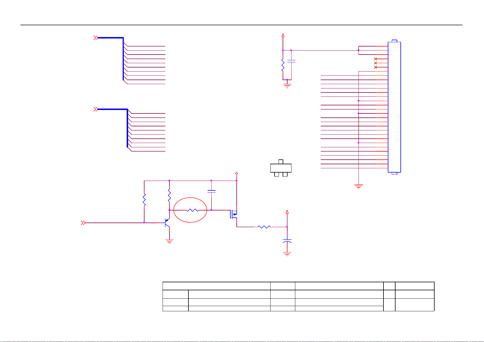
17" LCD Color Monitor HP L1750
7.4 USB Board
C701
1uF/16V
100K 1/16W 5%
GND_U
C708 18pF
1M 1/16W 5%
C713 18pF
GND_U
CN703
CONN
R701
/OCS1
/OCS2
R724
+3.3V_U SB
GND_U
1
2
GND_U
R704
100K 1/16W 5%
GND_U
R717
100K 1/16W 5%
C705
0.1uF/16V
GND_U
R716
100K 1/16W 5%
GND_U
12
GND_U
+5V
GND_U
U701 USB2512-AEZ G
27
VBUS_DET
Downs tream 1
13
OCS1
Downs tream 2
17
OCS2
Downs tream 3
19
NC
Downs tream 4
21
NC
EEPROM/ Co n f i g
SDA/SMBDATA/N ON_REM1
26
RESET
28
LOCAL_PWR /NON_REM0/SU SP_IND
11
TEST
33
XTAL 1/ C L K I N
X70 1
24.000MHz
32
XTAL2/CLKIN_EN
37
VSS(FLAG)
+
C723
470uF/16V
GND_U
C722
0.1uF/16V
Upstream
USBUP_DM
USBUP_DP
USBDN1_DM
USBDN1_DP
PRTPWR1
USBDN2_DM
USBDN2_DP
PRTPWR2
SCL/SMBCLK/ CFG_SEL0
HS_IND/CFG_SEL1
Common
VDD33
VDD33CR
VDDA33
VDDA33
VDDA33
VDDA33/ VDD33PLL
VDD18
VDDA18PLL
U703
VOUTVIN
VSS
AP1117E33LA
1
GND_U
RBIAS
23
30
31
1
2
12
3
4
16
6
NC
7
NC
18
NC
8
NC
9
NC
20
NC
22
24
25
35
23
15
5
10
29
36
14
34
+3.3V _USB
+
GND_U
GND_U
GND_U
GND_U
GND_U
C720
100uF/16V
DM1
DP1
DM2
DP2
R721
12K 1/10W 1%
GND_U
C709
0.1uF/ 16V
GND_U
C714
0.1uF/ 16V
C718
0.1uF/ 16V
C721
0.1uF/ 16V
GND_U
+3.3V_U SB
R706
+3.3V_U SB
R710
C706
4.7UF 16V
C710
0.1uF/16V
GND_U
GND_U
NC
NC
R718
GND_U
C715
1uF/16V
C719
1uF/16V
R707
R711
R72710K 1/16W 5%
NC
GND_U
GND_U
NC
NC
R719
GND_U
C707
0.1uF/16V
C711
0.1uF/16V
R71310K 1/16W 5%
NC
GND_U
R720
GND_U
+3.3V _USB
C724
0.1uF/ 16V
GND_U
+3.3V_U SB
R71410K 1/16W 5%
NC
GND_U
C712
0.1uF/16V
GND_U
C704
0.1uF/ 16V
U702
8
VCC
7
WP
6
SCL
M24C02-WMN6TP
R702 0R05 1/ 16W
L701 NC
1
2
DM0
DP0
R703 0R05 1/ 16W
+5V
12
t
R708
10K 1/16W 5%
/OCS1
R709
15K 1/16W 5%
GND_U
R712 0R05 1/ 16W
DM1
1
A0
2
A1
3
A2
45
GNDSDA
GND_U
DP1
R715 0R05 1/ 16W
R722 0R05 1/ 16W
DM2
DP2
R723 0R05 1/ 16W
+5V
12
R725
10K 1/16W 5%
/OCS2
R726
15K 1/16W 5%
GND_U
T P V ( Top Victory Electronics Co . , Ltd. )
G2704-D-x-x -1-20070710
絬 隔 瓜 絪 腹
Key Component
02.USB H UB USB2514
Date
3
F701
PTCR
GND_U
L702 NC
2
3
L703 NC
2
3
F702
PTCR
t
GND_U
4
FB701 120 OHM
1 2
C702
+
100uF/16V
1
4
1
4
FB702 120 OHM
1 2
C716
+
100uF/16V
NC
GND
GND_U
NC
GND
NC
GND
GND_U
1 2
1 2
1 2
ZD701
C703
0.1uF/ 16V
ZD703
ZD705
C717
0.1uF/ 16V
1
34
2
3
12
4
NC
6 5
CN701
GND_U
CONNNECTOR
ZD702
1 2
GND
R705 0R 05 1/8W
GND_U
NC
ZD704
12
1 2
11
GND
GND
NC
ZD706
1 2
GND
HP L1750/L1950 Custom
OEM MOD EL Size
TPV MODEL
<Doc > D
PCB NAME
G2704-D
Sheet
22Tuesday, J uly 10, 2007
GND_U
GND_U
of
GND
GND
CN702
123
4
CONNNECTOR
1234
10
5678
9
657
8
GND
Rev
备注
称爹
31
Page 32

17" LCD Color Monitor HP L1750
8. PCB Layout
8.1 Main Board
32
Page 33

17" LCD Color Monitor HP L1750
33
Page 34

17" LCD Color Monitor HP L1750
8.2 Power Board
34
Page 35

17" LCD Color Monitor HP L1750
35
Page 36

17" LCD Color Monitor HP L1750
8.3 Key Board
36
Page 37

17" LCD Color Monitor HP L1750
8.4 USB BOARD
37
Page 38

17" LCD Color Monitor HP L1750
38
Page 39

17" LCD Color Monitor HP L1750
9. Maintainability
9.1Equipments and Tools Requirement
1. Multi-meter.
2. Oscilloscope.
3. Pattern Generator.
4. DDC Tool with a Compatible Computer.
5. Alignment Tool.
6. LCD Color Analyzer.
7. Service Manual.
8. User Manual.
39
Page 40

17" LCD Color Monitor HP L1750
9.2 Trouble Shooting
9.2.1 Main Board
1、No power
Press power key and look if the
picture is normal
Please reinsert and make sure the
AC of 100-240 is normal
Measure U701 PIN 2=3.3V
Q403 = 3.3V
No power
NG
OK
OK
NG
NG
Reinsert or check the
power section
Measure CN401 PIN5/6=5V?
X201 oscillate waveforms are
normal
NG
OK
Replace U401
Replace X201
Check power section
Chec
Replace U701/Q403
40
Page 41

17" LCD Color Monitor HP L1750
No picture (LED is orange)
No picture
Measure Q202=3.3V R205 = 3.3V
NG
OK
Replace Q202/R205
X201 oscillate waveforms
are normal
NG
OK
Check if the sync signal from
computer is output and video cable
is connected normally
Replace X201
OK
NG
Input the sync signal of computer, or
change the cable
Replace U401
41
Page 42

17" LCD Color Monitor HP L1750
9.2.2 Power Board
1. No Power
No power
Check AC line volt 110V or 220V
OK
NG
Check AC line
Check the voltage of C907(+)
OK
Check start voltage for the pin8of IC901
NG
Check F901, bridge rectified circuit
OK
NG
Check R910,IC901
Check the auxiliary voltage is between 10V-16V
Check IC901,T901, D905,D906,D907
42
Page 43

17" LCD Color Monitor HP L1750
2. W/LED No Backlight
Check C812 (+) =12V
OK
NG
Check Q806
Check ON/OFF signal
NG
OK
Check Interface board
Check IC801 pin2=5V ?
Check the pin1 of IC801 have saw tooth wave
OK
NG
Change Q802 or Q803
NG
OK
Change IC801
Check ZD803 has the output of square wave at short time.
NG
O
CheckQ805/Q806
Check the resonant wave of pin2 & pin5 for T801
OK
NG
Check Q801/Q811/D806/D807/D808
Check the output of T801
NG
OK
Change T801
Check connecter & lamp
43
Page 44

17" LCD Color Monitor HP L1750
9.2.3 Key Board
OSD is unstable or not working
Is Keypad board connecting normally?
NG
Connect Keypad Board
OK
Is Button Switch normally?
NG
Replace Button Switch
OK
Is Keypad board normally?
NG
Replace Keypad Board
OK
Check main board
44
Page 45

17" LCD Color Monitor HP L1750
10. White- Balance, Luminance Adjustment
Approximately 30 minutes should be allowed for warm up before proceeding
White-Balance adjustment.
1. How to do the Chroma-7120 MEM .Channel setting
A. Reference to chroma 7120 user guide
B. Use “ SC” key and “ NEXT” key to modify xyY value and use “ID” key to modify the
TEXT description Following is the procedure to do white-balance adjust
2. Setting the color temp. You want
A. 9300k color:
9300 color temp. parameter is x = 283 ±15, y = 297 ±15, Y> 190 cd/m
B. sRGB color:
sRGB color temp. parameter is x = 313±15, y = 329 ±15, Y>200 cd/m
C. 6500K color:
6500K color temp. parameter is x = 313±15, y = 329 ±15, Y>230 cd/m2)
2 ,
2
)
3. Into factory mode of HP L1750
Turn on power, press the Menu button, pull out the power cord, and then plug the power cord. Then the
factory OSD will be at the left top of the panel.
4. Bias adjustment:
Set the Contrast
to 80
Adjust the Brightness
5. Gain adjustment :
Move cursor to “-F-” and press MENU key
A. Adjust 9300k color-temperature
1. Switch the Chroma-7120 to 9300k channel.
2. The chroma 7120 will show x = 283±15, y = 297 ±15, Y>190 cd/m
3. Switch the chroma-720 to RGB MODE (with press “MODE” button to change )
4. Adjust the RED of color 9300K on factory window until chroma 7120 indicator reached
to 90.
2
the value R=100
5. Adjust the GREEN of color 9300K on factory window until chroma 7120 indicator reached
the value G=100
6. Adjust the BLUE of color 9300K on factory window until chroma 7120 indicator reached
the value B=100
7. Repeat above procedure ( item 4,5,6) until chroma 7120 RGB value meet the
tolerance =100±2
45
Page 46

17" LCD Color Monitor HP L1750
B. Adjust sRGB color-temperature
1. Switch the chroma-7120 to sRGB channel.
2. The chroma 7120 will show x = 313 ±15, y = 329 ±15, Y >200 cd/m
3. Switch the chroma 7120 l to RGB MODE ( with press “MODE” button to change )
4. Adjust the RED of color sRGB on factory window until chroma 7120 indicator reached
the value R=100
5. Adjust the GREEN of color sRGB on factory window until chroma 7120 indicator reached
the value G=100
6. Adjust the BLUE of color sRGB on factory window until chroma 7120 indicator reached
the value B=100
7. Repeat above procedure ( item 4,5,6) until chroma 7120 RGB value meet the
tolerance =100±2
C. Adjust 6500k color-temperature
1. Switch the chroma-7120 to 6500K channel.
2. The chroma 7120 will show x = 313 ±15, y = 329 ±15, Y >230 cd/m
2
2
3. Switch the chroma 7120 l to RGB MODE ( with press “MODE” button to change )
4. Adjust the RED of color sRGB on factory window until chroma 7120 indicator reached
the value R=100
5. Adjust the GREEN of color sRGB on factory window until chroma 7120 indicator reached
the value G=100
6. Adjust the BLUE of color sRGB on factory window until chroma 7120 indicator reached
the value B=100
7. Repeat above procedure ( item 4,5,6) until chroma 7120 RGB value meet the
tolerance =100±2
D. Press reset key and Turn the Power-button “off to on” to quit from factory mode.
46
Page 47

17" LCD Color Monitor HP L1750
11. Mechanical Instructions
Step Figure Description
Lay the monitor
Preparation
on a flat, soft
and clean
surface.
Remove the
stand
Remove the
decorate cover
and the screws
to remove the
stand.
47
Page 48

17" LCD Color Monitor HP L1750
Remove the
back cover
AL TAPE
SHIELD
Remove the
back cover
Remove the
screws to
remove the
bezel
Update.
Cancel
“AL TAPE “,
Remove the
bezel
Add
“SHIELD”
48
Page 49

17" LCD Color Monitor HP L1750
Remove the
main frame
screws marked
Remove the
in red and to
remove the
main frame
Put this
cover up.
49
Page 50

17" LCD Color Monitor HP L1750
Remove
the
panel
Remove the
panel
50
Page 51

17" LCD Color Monitor HP L1750
1.Remove the
screws marked
Remove
main board
and power
board
in red to
remove the
Power Board、
USB Board
and Main
Board.
2.Disconnect
the connector
and remove
the Power
Board、USB
Board and
Main Board.
51
Page 52

17" LCD Color Monitor HP L1750
The end
The machine
disconnect
freely
52
Page 53

17" LCD Color Monitor HP L1750
12. Monitor Exploded View
53
Page 54

17" LCD Color Monitor HP L1750
13. BOM List
T77AMMDKHNHPQNE
Location Part No. Description
040G 58162435A P/N LABEL FOR MANUAL PE BAG
040G 581654 3A CARTON LABEL
052G 1185 MIDDLE TAPE
052G 1205 A ALUMINIUM TAPE
052G 1207 A
052G 1211503 ALUMINUM FOIL TAPE
089G 175517 G USB CABLE
E08902 089G 728HAAE03 SINGNAL CABLE 1.8M
E08903 089G1748HAA 9 DVI SIGNAL CABLE
E08901 089G402A19N IS AC POWER CABLE
E09503 095G8014 6D 44 HARNESS 6P-6P 250mm
0D1G 930 4120 screw
0D1G 930 6 47 CR3 SCREW
0D1G1730 8120 SCREW
0D1G1730 8120 SCREW
0D1G1730 8120 SCREW
0M1G 130 6120 SCREW M3X6
0M1G 140 10225 CR3 SCREW
705GH734060 STAND-BASE ASS'Y
705GH734062 BEZEL ASS'Y
Conductive Tape 45mm *25mm *0.08mm (单导)
E750 750GLU70G1D12Z000H PANEL M170EG01 VD00 SZ AUO
A15G0250 1104A MAIN FRAME
M034 A34G0418 EY 1B REAR COVER 17
CBPC7AMMHPH1 MAIN BOARD
H40G 17N69015C L1750 ID LABEL
H40G 17N69016B ID LABEL
H40G 581690 8A TCO'03 LABEL
H41G160669013D L1*50g DOCKIT NA
H41G780069099C SCREEN FLY (311618-007)
H41G780669028D L1*50g QSG 449163-B26
H41G780669058A RTF CARD 488950-B21
H41G780669059A RTF CARD 407430-005
H44G7012 1 EPS
H44G7012 2 EPS
H44G7012690 1B 17 LCD CARTON(447868-00A)
H44G7012BRO 1A PAPER SHEET
H44G9004 3 EPE BOARD
54
Page 55

17" LCD Color Monitor HP L1750
H45G 77 6 PE PACKING
H45G 87 18 9H A EPE COVER
H45G 87 1810H A EPE COVER FOR BASE
H50G 506 2 CIRCLE BELT
H52G6025 16 33 MYLAR PET 0.25MM 145*50MM
H85G0006 1 SHIELD
KEPC7HC5 KEY BOARD
PWPC741AH1 POWER BOARD G2655-2-X-X-2-080528
Q23G3178690 8A logo
Q45G 76 28 H A PE BAG FOR MANUAL
E08907 S89G179T30N18 LVDS ASSY
USB7HA1 USB BOARD
012G 394 6 FOOT PORON
0M1G 140 12125 SCREW
0Q1G 130 8120 SCREW 42A9930011
0Q1G 130 8120 SCREW 42A9930011
0Q1G 130 8120 SCREW 42A9930011
0Q1G 330 8120 SCREW 3X8mm 42A9930017/ 42-D002093
A15G0289 1102A MAFN FRAME
A33G0278 EY L BASE_CAP
A33G0279 EY L HOOK COVER
A33G0280 EY L COVER_PIVOT_FRONT
A33G0281 EY L COVER_TILT_FRONT
A33G0282 EY L TILT COVER(REAR)
A34G0419 PC B BASE RING
A34G0420 EY B BASE COVER
A34G0423 EY B COVER_RAM_TOP
A34G0424 EY B COVER_RAM_BOTTOM
A34G0426 EY B COVER_PIVOT_REAR
A37G0048 1 Hinge ass'y
H19G0001 1 LOCK PIN
H40G 581690 9C L1*50 caution label
A33G0237 PC L BUTTON_POWER
A33G0238 PC L OSD BUTTON
A33G0239 1 1C LENS_POWER
A34G0417 PCA1B BEZEL
CN201 033G3802 6B Y L WAFER
CN401 033G3802 9B Y W WAFER
CN301 033G801930F CH JS CONNECTOR
040G 45762412B CBPC LABEL
55
Page 56

17" LCD Color Monitor HP L1750
R402 061G152M33964L6W56 RST MOFR 3.3 0HM +-5% 2WS
C202 067G215V100 7R LOW E.S.R 10uF M 50V
C220 067G215V100 7R LOW E.S.R 10uF M 50V
C303 067G405V101 3P
C402 067G405V101 3P
C407 067G405V101 3P
C408 067G405V101 3P
CN101 088G 35315F HD D-SUB CONN F ATTACHED SCREW
CN102 088G 35424F J DVI 24PIN CONN F ATTACHED SCREW
X201 093G 2253B H XAT01431AFI1H-3OHX AT-49 14.31818MHZ
Q85G 583603 GASKET_ALUMINIUM FOIL
Q85G 583605 GASKET_ALUMINIUM FOIL
U401 056G 562184 IC HUM56AWL-LF PQFP-100
U702 056G 56327A IC AP1117E18LA SOT223-3L ANACHIP
U701 056G 585 4A IC AP1117E33L-13
U204 056G1133 32 IC M24C04-WMN6TP SO8
U101 056G1133 34 M24C02-WMN6TP
U102 056G1133 34 M24C02-WMN6TP
U402 056G1133713 IC PM25LV010A-100SCE SOIC-8
CAP 105℃ 100UF M 16V
CAP 105℃ 100UF M 16V
CAP 105℃ 100UF M 16V
CAP 105℃ 100UF M 16V
Q201 057G 417 12 T KEC 2N3904S-RTK/PS
Q403 057G 417 12 T KEC 2N3904S-RTK/PS
Q301 057G 417 13 T KEC 2N3906S-RTK/PS
Q203 057G 417 13 T KEC 2N3906S-RTK/PS
Q202 057G 417 13 T KEC 2N3906S-RTK/PS
Q302 057G 763 1 A03401 SOT23 BY AOS(A1)
R201 061G0402000 6857 RST CHIPR 0 OHM +-5% 1/16W
R101 061G0402000 6857 RST CHIPR 0 OHM +-5% 1/16W
R136 061G0402100 6857 RST CHIP 10R 1/16W 5%
R133 061G0402100 6857 RST CHIP 10R 1/16W 5%
R131 061G0402100 6857 RST CHIP 10R 1/16W 5%
R130 061G0402100 6857 RST CHIP 10R 1/16W 5%
R129 061G0402100 6857 RST CHIP 10R 1/16W 5%
R128 061G0402100 6857 RST CHIP 10R 1/16W 5%
R127 061G0402100 6857 RST CHIP 10R 1/16W 5%
R126 061G0402100 6857 RST CHIP 10R 1/16W 5%
R219 061G0402104 6857 RST CHIP 100K 1/16W 5%
R105 061G0402222 6857 RST CHIPR 2.2KOHM +-5% 1/16W F
R106 061G0402222 6857 RST CHIPR 2.2KOHM +-5% 1/16W F
R202 061G0402223 6857 RST CHIP 22K 1/16W 5%
R204 061G0402390 0F6857 RST CHIP 390R 1/16W 1%
56
Page 57

17" LCD Color Monitor HP L1750
R404 061G0402472 6857 RST CHIPR 4.7KOHM +-5% 1/16W
R303 061G0402472 6857 RST CHIPR 4.7KOHM +-5% 1/16W
R218 061G0402472 6857 RST CHIPR 4.7KOHM +-5% 1/16W
R217 061G0402472 6857 RST CHIPR 4.7KOHM +-5% 1/16W
R135 061G0402472 6857 RST CHIPR 4.7KOHM +-5% 1/16W
R134 061G0402472 6857 RST CHIPR 4.7KOHM +-5% 1/16W
R121 061G0402472 6857 RST CHIPR 4.7KOHM +-5% 1/16W
R120 061G0402472 6857 RST CHIPR 4.7KOHM +-5% 1/16W
R216 061G0402560 6857 RST CHIP 56R 1/16W 5%
R233 061G0402682 6857 RST CHIPR 6.8KOHM +-5% 1/16W
R208 061G0402682 6857 RST CHIPR 6.8KOHM +-5% 1/16W
R139 061G0402682 6857 RST CHIPR 6.8KOHM +-5% 1/16W
R107 061G0402750 6857 RST CHIPR 75 OHM +-5% 1/16W
R112 061G0402750 6857 RST CHIPR 75 OHM +-5% 1/16W
R116 061G0402750 6857 RST CHIPR 75 OHM +-5% 1/16W
R212 061G0402750 6857 RST CHIPR 75 OHM +-5% 1/16W
FB205 061G0805000 6857 RST CHIPR 0 OHM +-5% 1/8W
FB206 061G0805000 6857 RST CHIPR 0 OHM +-5% 1/8W
FB301 061G0805000 6857 RST CHIPR 0 OHM +-5% 1/8W
R302 061G0805331 6857 RST CHIP 330 OHM 1/8W 5%
C215 065G0402104 156785 MLCC 0402 CAP 0.1UF K 1
C216 065G0402104 156785 MLCC 0402 CAP 0.1UF K 1
C217 065G0402104 156785 MLCC 0402 CAP 0.1UF K 1
C219 065G0402104 156785 MLCC 0402 CAP 0.1UF K 1
C223 065G0402104 156785 MLCC 0402 CAP 0.1UF K 1
C225 065G0402104 156785 MLCC 0402 CAP 0.1UF K 1
C226 065G0402104 156785 MLCC 0402 CAP 0.1UF K 1
C227 065G0402104 156785 MLCC 0402 CAP 0.1UF K 1
C228 065G0402104 156785 MLCC 0402 CAP 0.1UF K 1
C229 065G0402104 156785 MLCC 0402 CAP 0.1UF K 1
C231 065G0402104 156785 MLCC 0402 CAP 0.1UF K 1
C301 065G0402104 156785 MLCC 0402 CAP 0.1UF K 1
C302 065G0402104 156785 MLCC 0402 CAP 0.1UF K 1
C401 065G0402104 156785 MLCC 0402 CAP 0.1UF K 1
C405 065G0402104 156785 MLCC 0402 CAP 0.1UF K 1
C409 065G0402104 156785 MLCC 0402 CAP 0.1UF K 1
C410 065G0402104 156785 MLCC 0402 CAP 0.1UF K 1
C411 065G0402104 156785 MLCC 0402 CAP 0.1UF K 1
C214 065G0402104 156785 MLCC 0402 CAP 0.1UF K 1
C112 065G0402104 156785 MLCC 0402 CAP 0.1UF K 1
57
Page 58

17" LCD Color Monitor HP L1750
C114 065G0402104 156785 MLCC 0402 CAP 0.1UF K 1
C115 065G0402104 156785 MLCC 0402 CAP 0.1UF K 1
C116 065G0402104 156785 MLCC 0402 CAP 0.1UF K 1
C117 065G0402104 156785 MLCC 0402 CAP 0.1UF K 1
C118 065G0402104 156785 MLCC 0402 CAP 0.1UF K 1
C119 065G0402104 156785 MLCC 0402 CAP 0.1UF K 1
C201 065G0402104 156785 MLCC 0402 CAP 0.1UF K 1
C203 065G0402104 156785 MLCC 0402 CAP 0.1UF K 1
C213 065G0402104 156785 MLCC 0402 CAP 0.1UF K 1
C212 065G0402104 156785 MLCC 0402 CAP 0.1UF K 1
C211 065G0402104 156785 MLCC 0402 CAP 0.1UF K 1
C210 065G0402104 156785 MLCC 0402 CAP 0.1UF K 1
C208 065G0402104 156785 MLCC 0402 CAP 0.1UF K 1
C207 065G0402104 156785 MLCC 0402 CAP 0.1UF K 1
C206 065G0402104 156785 MLCC 0402 CAP 0.1UF K 1
C205 065G0402104 156785 MLCC 0402 CAP 0.1UF K 1
C204 065G0402104 156785 MLCC 0402 CAP 0.1UF K 1
C102 065G0402220 316785 CAP MLCC 22PF 50V NPO
C103 065G0402220 316785 CAP MLCC 22PF 50V NPO
C224 065G0402224 176785 MLCC 0402 0.22UF Z 16V Y5V
C218 065G0402224 176785 MLCC 0402 0.22UF Z 16V Y5V
C222 065G0402270 316785 CAP 0402 27PF J 50V NPO
C221 065G0402330 316785 CAP 0402 33PF J 50V EYA
C113 065G0402473 126785 CAP MLCC 47NF 16V X7R
C110 065G0402473 126785 CAP MLCC 47NF 16V X7R
C109 065G0402473 126785 CAP MLCC 47NF 16V X7R
C107 065G0402473 126785 CAP MLCC 47NF 16V X7R
C105 065G0402473 126785 CAP MLCC 47NF 16V X7R
C101 065G0402473 126785 CAP MLCC 47NF 16V X7R
C104 065G0402509 316785 CAP MLCC 5PF 50V NPO
C108 065G0402509 316785 CAP MLCC 5PF 50V NPO
C111 065G0402509 316785 CAP MLCC 5PF 50V NPO
FB104 071G 56K121 M CHIP BEAD
FB204 071G 56V301 B CHIP BEAD FCM2012VF-301T07 bullwill
FB203 071G 56V301 B CHIP BEAD FCM2012VF-301T07 bullwill
FB201 071G 56V301 B CHIP BEAD FCM2012VF-301T07 bullwill
FB101 071G 59K190 B 19 OHM BEAD
FB102 071G 59K190 B 19 OHM BEAD
FB103 071G 59K190 B 19 OHM BEAD
D105 093G 64 42 P BAV70 SOT23 BY PAN JIT
58
Page 59

17" LCD Color Monitor HP L1750
D101 093G 64 42 P BAV70 SOT23 BY PAN JIT
D117 093G 6433S DIODE BAV99 SEMTECH
D116 093G 6433S DIODE BAV99 SEMTECH
D115 093G 6433S DIODE BAV99 SEMTECH
D114 093G 6433S DIODE BAV99 SEMTECH
D113 093G 6433S DIODE BAV99 SEMTECH
D112 093G 6433S DIODE BAV99 SEMTECH
D111 093G 6433S DIODE BAV99 SEMTECH
D110 093G 6433S DIODE BAV99 SEMTECH
D104 093G 6433S DIODE BAV99 SEMTECH
D103 093G 6433S DIODE BAV99 SEMTECH
D102 093G 6433S DIODE BAV99 SEMTECH
ZD106 093G 39GA01 T RLZ5.6B
ZD105 093G 39GA01 T RLZ5.6B
ZD104 093G 39GA01 T RLZ5.6B
ZD103 093G 39GA01 T RLZ5.6B
ZD102 093G 39GA01 T RLZ5.6B
ZD101 093G 39GA01 T RLZ5.6B
D109 093G 39GA01 T RLZ5.6B
D108 093G 39GA01 T RLZ5.6B
D107 093G 39GA01 T RLZ5.6B
D106 093G 39GA01 T RLZ5.6B
E715 715G2559 2 36995 MAIN BOARD PCB
R102 061G0402101 6805 RST CHIPR 100 OHM +-5% 1/16W
R103 061G0402101 6805 RST CHIPR 100 OHM +-5% 1/16W
R104 061G0402101 6805 RST CHIPR 100 OHM +-5% 1/16W
R108 061G0402101 6805 RST CHIPR 100 OHM +-5% 1/16W
R110 061G0402101 6805 RST CHIPR 100 OHM +-5% 1/16W
R111 061G0402101 6805 RST CHIPR 100 OHM +-5% 1/16W
R113 061G0402101 6805 RST CHIPR 100 OHM +-5% 1/16W
R114 061G0402101 6805 RST CHIPR 100 OHM +-5% 1/16W
R115 061G0402101 6805 RST CHIPR 100 OHM +-5% 1/16W
R117 061G0402101 6805 RST CHIPR 100 OHM +-5% 1/16W
R119 061G0402101 6805 RST CHIPR 100 OHM +-5% 1/16W
R122 061G0402101 6805 RST CHIPR 100 OHM +-5% 1/16W
R207 061G0402101 6805 RST CHIPR 100 OHM +-5% 1/16W
R213 061G0402101 6805 RST CHIPR 100 OHM +-5% 1/16W
R214 061G0402101 6805 RST CHIPR 100 OHM +-5% 1/16W
R215 061G0402101 6805 RST CHIPR 100 OHM +-5% 1/16W
R222 061G0402101 6805 RST CHIPR 100 OHM +-5% 1/16W
59
Page 60

17" LCD Color Monitor HP L1750
R224 061G0402101 6805 RST CHIPR 100 OHM +-5% 1/16W
R225 061G0402101 6805 RST CHIPR 100 OHM +-5% 1/16W
R406 061G0402102 6805 RST CHIPR 1k OHM +-5% 1/16W
R118 061G0402103 6805 RST CHIPR 10K OHM +-5% 1/16W
R123 061G0402103 6805 RST CHIPR 10K OHM +-5% 1/16W
R132 061G0402103 6805 RST CHIPR 10K OHM +-5% 1/16W
R137 061G0402103 6805 RST CHIPR 10K OHM +-5% 1/16W
R138 061G0402103 6805 RST CHIPR 10K OHM +-5% 1/16W
R203 061G0402103 6805 RST CHIPR 10K OHM +-5% 1/16W
R205 061G0402103 6805 RST CHIPR 10K OHM +-5% 1/16W
R209 061G0402103 6805 RST CHIPR 10K OHM +-5% 1/16W
R210 061G0402103 6805 RST CHIPR 10K OHM +-5% 1/16W
R211 061G0402103 6805 RST CHIPR 10K OHM +-5% 1/16W
R223 061G0402103 6805 RST CHIPR 10K OHM +-5% 1/16W
R226 061G0402103 6805 RST CHIPR 10K OHM +-5% 1/16W
R227 061G0402103 6805 RST CHIPR 10K OHM +-5% 1/16W
R230 061G0402103 6805 RST CHIPR 10K OHM +-5% 1/16W
R231 061G0402103 6805 RST CHIPR 10K OHM +-5% 1/16W
R232 061G0402103 6805 RST CHIPR 10K OHM +-5% 1/16W
R234 061G0402103 6805 RST CHIPR 10K OHM +-5% 1/16W
R301 061G0402103 6805 RST CHIPR 10K OHM +-5% 1/16W
R401 061G0402103 6805 RST CHIPR 10K OHM +-5% 1/16W
R403 061G0402103 6805 RST CHIPR 10K OHM +-5% 1/16W
R405 061G0402103 6805 RST CHIPR 10K OHM +-5% 1/16W
R228 061G0402392 6805 RST CHIPR 3.9KOHM +-5%
R229 061G0402392 6805 RST CHIPR 3.9KOHM +-5%
R304 061G0402473 6805 RST CHIPR 47K OHM +-5%
CN001 033G3802 6 BH L WAFER
SW004 077G 602 7 HJ SWITCH
SW003 077G 602 7 HJ SWITCH
SW002 077G 602 7 HJ SWITCH
SW001 077G 602 7 HJ SWITCH
LED001 081G 121C1 GP LED GP32032CE/P310-ZY-50-HB
GND001 095G 900633 WIRE HARNESS
009G6005 1 GROUND TERMINAL
CN804 033G8021 2E U INVERT CONNECTOR
CN803 033G8021 2E U INVERT CONNECTOR
CN802 033G8021 2E U INVERT CONNECTOR
CN801 033G8021 2E U INVERT CONNECTOR
040G 45762412B CBPC LABEL
60
Page 61
17" LCD Color Monitor HP L1750
055G 23524 WELDING FLUX WITHOUT PB
055G 100611 TIN STICK W/O PB
IC902 056G 139 3A IC PC123Y22FZ0F
NR901 061G 58080 WT6872 RST NTCR 8 OHM
C905 063G107K2246S1 X2 CAP 0.22UF K 275VAC
C903 063G107K2246S1 X2 CAP 0.22UF K 275VAC
C817 065G 3J2096ET 2PF 5% SL 3KV
C816 065G 3J2206ET 22PF 5% SL 3KV TDK
C824 065G 3J2706ET 27PFJ 3KV SL
C819 065G 3J5606ET CAP CER 56PF J 3KV
C820 065G 3J5606ET CAP CER 56PF J 3KV
C821 065G 3J5606ET CAP CER 56PF J 3KV
C822 065G 3J5606ET CAP CER 56PF J 3KV
C904 065G306M1022BP 1000PF Y1.CAP
C901 065G306M2222BP 2200PF +-20% 250VAC
C902 065G306M2222BP 2200PF +-20% 250VAC
C900 065G306M3322BP 3300PF 20%
C907 067G 40Z12115K EC 120uF V 450V 20*40mm
C918 067G215D6814KV
C917 067G215D6814KV
C812 067G215S1024KV
C915 067G215S4713KV
C939 067G215V102 3N
C940 067G215V102 3R LOW E.S.R 1000UF +/-20% 16V
L801 073G 174 35DNA FILTER 200mH±25%
L802 073G 174 35DNA FILTER 200mH±25%
L904 073G 253191 H IND CHOKE 1.1uH DADON
L903 073G 253191 H IND CHOKE 1.1uH DADON
T801 080GL19T 28 DN X'FMR 890mH TK.2017R.101.070302
T901 080GL19T 29 T X'FMR 610uH SRW24LQ-T20H017
CN901 087G 501 32 DL AC SOCKET DIP 3PIN+2PIN GROUND
CAP 105℃ 680uF M 25V
CAP 105℃ 680uF M 25V
EC 105℃ CAP 1000UF M 25V
EC 105℃ CAP 470UF M 16V
EC CAP 105 度 1000UF M 16V NCC
CN902 095G801410WE12 HARNESS 7P-9P-2P 130mm
705GH957001 Q901 ASS'Y
705GH993001 D906 ASS'Y
705GH993002 D907 ASS'Y
L902 S73L17440VG TRANSFORMER
BD901 093G 50460900 BRIDEGE DIODE GBU408 LITEON
CN703 033G3802 2B Y W CONNECTOR
040G 45762412B CBPC LABEL
C723 067G215S4713KV
EC 105℃ CAP 470UF M 16V
61
Page 62

17" LCD Color Monitor HP L1750
C720 067G305V101 36069
ELCAP 100UF +-20% 16V 105℃
C716 067G305V101 36069
C702 067G305V101 36069
CN702 088G 350 1 CL USB CONN AX2
CN701 088G 3512B1 CL USB CONN BLACK
X701 093G 2245B HE XTL XAT024000FI1H-3OX AT-49 24.000MHZ
R002 061G0603180 1F6857 RST CHIPR 1.8 KOHM +-1% 1/10W
R001 061G0603300 1F6857 RST CHIPR 3KOHM +-1% 1/10W
R003 061G0603300 1F6857 RST CHIPR 3KOHM +-1% 1/10W
R004 061G0805000 6857 RST CHIPR 0 OHM +-5% 1/8W
FB005 071G 59B601 MA CHIP BEAD
FB004 071G 59B601 MA CHIP BEAD
FB003 071G 59B601 MA CHIP BEAD
FB002 071G 59B601 MA CHIP BEAD
FB001 071G 59B601 MA CHIP BEAD
E715 715G2579 2 6403 KEPC BOARD PCB
Q901 057G 667 21 STP10NK70ZFP
ELCAP 100UF +-20% 16V 105℃
ELCAP 100UF +-20% 16V 105℃
HS5 090G6064 1 HEAT SINK
0M1G1730 8120 SCREW
D906 093G 60245 SP10150 10A 150V ITO-220 BY SECOS
0M1G1730 8120 SCREW
HS1 H90G0009 1 HEAT SINK
D907 093G 60278 DIODE SP1060 ITO-220 SECOS
0M1G1730 8120 SCREW
HS2 H90G0009 1 HEAT SINK
IC901 056G 379 76 IC LD7552BPS SOP-8
IC801 056G 608 10 IC OZ9938GN-B SOIC-16
Q903 057G 417 4 PMBS3904/PHILIPS-SMT(04)
Q801 057G 417 4 PMBS3904/PHILIPS-SMT(04)
Q803 057G 759 2 RK7002FD5T116 SOT-23 BY ROHM
Q802 057G 759 2 RK7002FD5T116 SOT-23 BY ROHM
Q805 057G 763905 FET FDS8958A SO-8
Q806 057G 763905 FET FDS8958A SO-8
R846 061G0603000 6857 RST CHIPR 0 OHM +-5% 1/10W
R849 061G0603000 6857 RST CHIPR 0 OHM +-5% 1/10W
R926 061G0603100 1F6805 RST CHIPR 1KOHM +-1% 1/10W
R942 061G0603100 1F6805 RST CHIPR 1KOHM +-1% 1/10W
R816 061G0603100 2F6805 RST CHIPR 10KOHM +-1% 1/10W
R805 061G0603101 6857 RST CHIPR 100 OHM +-5% 1/10W
R806 061G0603101 6857 RST CHIPR 100 OHM +-5% 1/10W
62
Page 63

17" LCD Color Monitor HP L1750
R807 061G0603101 6857 RST CHIPR 100 OHM +-5% 1/10W
R808 061G0603101 6857 RST CHIPR 100 OHM +-5% 1/10W
R845 061G0603103 6857 RST CHIPR 10 KOHM +-5% 1/10W
R844 061G0603103 6857 RST CHIPR 10 KOHM +-5% 1/10W
R843 061G0603103 6857 RST CHIPR 10 KOHM +-5% 1/10W
R842 061G0603103 6857 RST CHIPR 10 KOHM +-5% 1/10W
R820 061G0603103 6857 RST CHIPR 10 KOHM +-5% 1/10W
R813 061G0603103 6857 RST CHIPR 10 KOHM +-5% 1/10W
R819 061G0603104 6857 RST CHIPR 100 KOHM +-5% 1/10W
R818 061G0603104 6857 RST CHIPR 100 KOHM +-5% 1/10W
R841 061G0603105 6857 RST CHIP 1M 1/10W 5%
R840 061G0603105 6857 RST CHIP 1M 1/10W 5%
R839 061G0603105 6857 RST CHIP 1M 1/10W 5%
R838 061G0603105 6857 RST CHIP 1M 1/10W 5%
R826 061G0603105 6857 RST CHIP 1M 1/10W 5%
R821 061G0603105 6857 RST CHIP 1M 1/10W 5%
R817 061G0603105 6857 RST CHIP 1M 1/10W 5%
R824 061G0603130 2F6857 RST CHIPR 13KOHM +-1% 1/10W
C808 061G0603184 6857 RST CHIP 180K 1/10W 5%
R801 061G0603242 6857 RST CHIPR 2.4 KOHM +-5% 1/10W
R930 061G0603243 1F6857 RST CHIPR 2.43KOHM +-1% 1/10W
R940 061G0603330 2F6857 RST CHIPR 33KOHM +-1% 1/10W
R823 061G0603360 0F6857 RST CHIPR 360R 1/10W 1%
R927 061G0603390 1F6857 RST CHIPR 3.9KOHM +-1% 1/10W
R825 061G0603511 6857 RST CHIPR 510 OHM +-5% 1/10W
R803 061G0603512 6857 RST CHIPR 5.1KOHM +-5% 1/10W
R804 061G0603512 6857 RST CHIPR 5.1KOHM +-5% 1/10W
R836 061G0603513 6857 RST CHIP 51K 1/10W 5%
R837 061G0603820 1F6857 RST CHIPR 8.2KOHM +-1% 1/10W
R925 061G0805100 1F6857 RST CHIPR 1KOHM +-1% 1/8W
R939 061G0805102 6857 RST CHIPR 1 KOHM +-5% 1/8W
R938 061G0805103 6857 RST CHIPR 10 KOHM +-5% 1/8W
R915 061G0805104 6857 RST CHIPR 100KOHM +-5% 1/8W
R924 061G0805150 0F6857 RST CHIPR 150OHM +-1% 1/8W
R822 061G0805191 2F RST CHIPR 19.1 KOHM +-1% 1/8W
R802 061G0805220 6857 RST CHIPR 22 OHM +-5% 1/8W
R943 061G0805471 6857 RST CHIPR 470 OHM +-5% 1/8W
R829 061G0805750 1F6857 RST CHIPR 7.5KOHM +-1% 1/8W
RJ901 061G1206000 6857 RST CHIP 0 OHM 1/4W 5%
RJ803 061G1206000 6857 RST CHIP 0 OHM 1/4W 5%
63
Page 64

17" LCD Color Monitor HP L1750
RJ802 061G1206000 6857 RST CHIP 0 OHM 1/4W 5%
RJ801 061G1206000 6857 RST CHIP 0 OHM 1/4W 5%
R910 061G1206100 6857 RST CHIPR 10 OHM +-5% 1/4W
R962 061G1206101 6857 RST CHIPR 100 OHM +-5% 1/4W
R961 061G1206101 6857 RST CHIPR 100 OHM +-5% 1/4W
R935 061G1206101 6857 RST CHIPR 100 OHM +-5% 1/4W
R920 061G1206101 6857 RST CHIPR 100 OHM +-5% 1/4W
R919 061G1206101 6857 RST CHIPR 100 OHM +-5% 1/4W
R918 061G1206101 6857 RST CHIPR 100 OHM +-5% 1/4W
R902 061G1206105 6857 RST CHIPR 1MOHM +-5% 1/4W
R901 061G1206105 6857 RST CHIPR 1MOHM +-5% 1/4W
R912 061G1206221 6857 RST CHIPR 220 OHM +-5% 1/4W
R905 061G1206304 6857 RST CHIPR 300KOHM +-5% 1/4W
R904 061G1206304 6857 RST CHIPR 300KOHM +-5% 1/4W
R906 061G1206304 6857 RST CHIPR 300KOHM +-5% 1/4W
R909 061G1206519 6857 RST CHIPR 5.1 OHM +-5% 1/4W
C805 065G0603103 326029 CAP 0603 0.01UF +-10% 50V X7R
C807 065G0603103 326029 CAP 0603 0.01UF +-10% 50V X7R
C932 065G0603103 326029 CAP 0603 0.01UF +-10% 50V X7R
C806 065G0603105 126029 CHIP 1UF 16VX7R 0603
C818 065G0603221 326785 CHIP 220PF 50V X7R
C814 065G0603391 316029 CHIP 390pF 50V NPO
C815 065G0603473 326029 CHIP 0.047UF 50V X7R
C810 065G0603473 326029 CHIP 0.047UF 50V X7R
C928 065G0805103 326029 CAP 0805 10NF +-10% 50V X7R
C913 065G0805104 326805 CAP 0805 0.1UF +-10% 50V X7R
C811 065G0805104 326805 CAP 0805 0.1UF +-10% 50V X7R
C924 065G0805104 326805 CAP 0805 0.1UF +-10% 50V X7R
C931 065G0805104 326805 CAP 0805 0.1UF +-10% 50V X7R
C804 065G0805225 126029 MLCC 0805 2.2UF K 16V X7R
C813 065G0805333 326029 CHIP 0.033UF 50V
C909 065G0805471 316857 CHIP 470PF 50V NPO
C801 065G0805473 326029 CAP 0805 0.047UFK 50V X7R
C802 065G0805473 326029 CAP 0805 0.047UFK 50V X7R
C809 065G080556131G6857 MLCC 0805 560PF G 50V NPO
C912 065G1206102 726857 CHIP 1000PF 500V X7R
C929 065G1206102 726857 CHIP 1000PF 500V X7R
C911 065G120622272K F CAP CHIP 1206 2200PF K 500V X7R
FB903 071G 56G301 EA
D808 093G 64 42 P BAV70 SOT23 BY PAN JIT
BEAD 300 欧
64
Page 65

17" LCD Color Monitor HP L1750
D807 093G 64 42 P BAV70 SOT23 BY PAN JIT
D806 093G 64 42 P BAV70 SOT23 BY PAN JIT
D903 093G 6432S 1N4148W
D805 093G 6432S 1N4148W
D804 093G 6432S 1N4148W
D803 093G 6432S 1N4148W
D802 093G 6432S 1N4148W
D801 093G 6432S 1N4148W
D809 093G 6433S DIODE BAV99 SEMTECH
ZD906 093G 39S 20 T RLZ22B LLDS
ZD801 093G 39S 24 T RLZ 5.6B LLDS
ZD802 093G 39S 24 T RLZ 5.6B LLDS
ZD803 093G 39S 24 T RLZ 5.6B LLDS
ZD922 093G 39S 24 T RLZ 5.6B LLDS
ZD902 093G 39S 40 T RLZ 13B LLDS
ZD921 093G 39S 40 T RLZ 13B LLDS
CN901 006G 31500 EYELET
T901 006G 31502 1.5MM RIVET
NR901 006G 31502 1.5MM RIVET
IC903 056G 158 10 T IC AS431AZTR-E1 TO-92
R903 061G152M10452T6W56 RST MOFR 100KOHM 5% 2WS
R946 061G152M47152T6W56 RST MOFR 470 OHM +-5% 2WS
R914 061G152M47852T6W56 RST MOFR 0.47 OHM +-5% 2WS"
R828 061G212Y62552T6W56 RST MGFR 6.2MOHM +-5% 1/2W
C938 065G 1K472 1T6921 CAP CER 4700PF 10% 1KV Y5P
C906 065G 2K152 1T6921 1.5NF/2KV Y5P +-10%
C936 065G 2K152 1T6921 1.5NF/2KV Y5P +-10%
C937 065G 2K152 1T6921 1.5NF/2KV Y5P +-10%
C908 067G215Y2207KT
FB902 071G 55 9 T FERRITE BEAD
FB901 071G 55 29 6100 PERRITE BEAD
CAP 105℃ 22UF M 50V KINGNICHI
F901 084G 56 3W FUSE
F903 084G 56 4W FUSE 4.0A 250V
D901 093G 6038T52T FR103
D900 093G1100 1152T DIODE PR1007R 1A/1000V DO-41
E715 715G2655 2 6403 POWER BOARD PCB
U703 056G 585 4A IC AP1117E33L-13
U701 056G 659 10 IC USB2512-AEZG QFN-36
U702 056G1133 34 M24C02-WMN6TP
F701 061G 56A075 LT SMD PTC 0.75A 1206L075.WR 1206
65
Page 66

17" LCD Color Monitor HP L1750
F702 061G 56A075 LT SMD PTC 0.75A 1206L075.WR 1206
R723 061G0402000 6857 RST CHIPR 0 OHM +-5% 1/16W
R722 061G0402000 6857 RST CHIPR 0 OHM +-5% 1/16W
R715 061G0402000 6857 RST CHIPR 0 OHM +-5% 1/16W
R712 061G0402000 6857 RST CHIPR 0 OHM +-5% 1/16W
R703 061G0402000 6857 RST CHIPR 0 OHM +-5% 1/16W
R702 061G0402000 6857 RST CHIPR 0 OHM +-5% 1/16W
R727 061G0402103 6857 RST CHIPR 10KOHM +-5% 1/16W
R725 061G0402103 6857 RST CHIPR 10KOHM +-5% 1/16W
R714 061G0402103 6857 RST CHIPR 10KOHM +-5% 1/16W
R713 061G0402103 6857 RST CHIPR 10KOHM +-5% 1/16W
R708 061G0402103 6857 RST CHIPR 10KOHM +-5% 1/16W
R701 061G0402104 6857 RST CHIP 100K 1/16W 5%
R704 061G0402104 6857 RST CHIP 100K 1/16W 5%
R716 061G0402104 6857 RST CHIP 100K 1/16W 5%
R717 061G0402104 6857 RST CHIP 100K 1/16W 5%
R724 061G0402105 6857 RST CHIP 1M 1/16W 5%
R709 061G0402153 6857 RST CHIP 15K 1/16W 5%
R726 061G0402153 6857 RST CHIP 15K 1/16W 5%
R721 061G0603120 2F6857 RST CHIP 12K 1/10W 1%
R705 061G0805000 6857 RST CHIPR 0 OHM +-5% 1/8W
C724 065G0402104 156785 MLCC 0402 CAP 0.1UF K 1
C722 065G0402104 156785 MLCC 0402 CAP 0.1UF K 1
C721 065G0402104 156785 MLCC 0402 CAP 0.1UF K 1
C718 065G0402104 156785 MLCC 0402 CAP 0.1UF K 1
C717 065G0402104 156785 MLCC 0402 CAP 0.1UF K 1
C714 065G0402104 156785 MLCC 0402 CAP 0.1UF K 1
C712 065G0402104 156785 MLCC 0402 CAP 0.1UF K 1
C711 065G0402104 156785 MLCC 0402 CAP 0.1UF K 1
C710 065G0402104 156785 MLCC 0402 CAP 0.1UF K 1
C709 065G0402104 156785 MLCC 0402 CAP 0.1UF K 1
C707 065G0402104 156785 MLCC 0402 CAP 0.1UF K 1
C705 065G0402104 156785 MLCC 0402 CAP 0.1UF K 1
C704 065G0402104 156785 MLCC 0402 CAP 0.1UF K 1
C703 065G0402104 156785 MLCC 0402 CAP 0.1UF K 1
C713 065G0402180 316785 CAP 0402 18PF J 50V NPO
C708 065G0402180 316785 CAP 0402 18PF J 50V NPO
C701 065G0603105 226805 CAP 0603 1UF +-10% 25V X7R
C715 065G0603105 226805 CAP 0603 1UF +-10% 25V X7R
C719 065G0603105 226805 CAP 0603 1UF +-10% 25V X7R
66
Page 67

17" LCD Color Monitor HP L1750
C706 065G080547515T MLCC 0805 CAP 4.7UF 16V X5R
FB701 071G 56K121 M CHIP BEAD
FB702 071G 56K121 M CHIP BEAD
E715 715G2704 2 6F2I USB BOARD
67
Page 68

17" LCD Color Monitor HP L1750
14. Different Parts List
Diversity of T77GMMDKHNHPQNE compared with T77AMMDKHNHPQNE
Location Part No. Description
E750 750GLG70E3L22Z000H PANEL LM170E03-TLL2 NJ LPL
A15G0250 1104L 17" MAIN FRAME
CBPC7LMMHPH1 CONVERSIONG2559-K-X-X-2-070630
PWPC741GH1 POWER G2655-2-X-X-1-080528
Diversity of T77GMMDTHNHPQNE compared with T77AMMDKHNHPQNE
Location Part No. Description
E750 750GLG70E3L22Z000H PANEL LM170E03-TLL2 NJ LPL
A15G0250 1104L 17" MAIN FRAME
CBPC7LMMHPH1 CONVERSIONG2559-K-X-X-2-070630
H41G160669016D L1*50g DOCKIT APD
PWPC741GH1 POWER G2655-2-X-X-1-080528
Diversity of T77CMMDKHNHPQNE compared with T77AMMDKHNHPQNE
Location Part No. Description
E750 750GLB70A7P41Z000H PANEL CLAA170EA07P 040 FQ CTOC
A15G0250 1104C 17" MAIN FRAME
CBPC7CMMHPH1 CONVERSIONG2559-K-X-X-2-070630
PWPC741CH1 POWER G2655-2-X-X-2-080528
Diversity of T77CMMDLHNHPQNE compared with T77AMMDKHNHPQNE
Location Part No. Description
E08901 089G412A19NIS3 POWER CORD
E750 750GLB70A7P41Z000H PANEL CLAA170EA07P 040 FQ CTOC
A15G0250 1104C 17" MAIN FRAME
CBPC7CMMHPH1 CONVERSIONG2559-K-X-X-2-070630
H40G 58169015A WARRANTY LABEL
H41G160669016D L1*50g DOCKIT APD
PWPC741CH1 POWER G2655-2-X-X-2-080528
Diversity of T77GMMDLHNHPQNE compared with T77AMMDKHNHPQNE
Location Part No. Description
E08901 089G412A19NIS3 POWER CORD
E750 750GLG70E3L22Z000H PANEL LM170E03-TLL2 NJ LPL
A15G0250 1104L 17" MAIN FRAME
CBPC7LMMHPH1 CONVERSIONG2559-K-X-X-2-070630
H40G 58169015A WARRANTY LABEL
68
Page 69

17" LCD Color Monitor HP L1750
H41G160669016D L1*50g DOCKIT APD
PWPC741GH1 POWER G2655-2-X-X-1-080528
Diversity of T77AMMDTHNHPQNE compared with T77AMMDKHNHPQNE
Location Part No. Description
H41G160669016D L1*50g DOCKIT APD
Diversity of T77CMMDTHNHPQNE compared with T77AMMDKHNHPQNE
Location Part No. Description
E750 750GLB70A7P41Z000H PANEL CLAA170EA07P 040 FQ CTOC
A15G0250 1104C 17" MAIN FRAME
CBPC7CMMHPH1 CONVERSIONG2559-K-X-X-2-070630
H41G160669016D L1*50g DOCKIT APD
PWPC741CH1 POWER G2655-2-X-X-2-080528
Diversity of T77AMMDBHNHPQNE compared with T77AMMDKHNHPQNE
Location Part No. Description
050G 600 1 W WHITE STRAP
E08901 089G404A19N IS POWER CORD
H41G160669017D L1*50g DOCKIT EMEA
H41G780669057A RTF CARD 488557-141
Diversity of T77CMMDBHNHPQNE compared with T77AMMDKHNHPQNE
Location Part No. Description
050G 600 1 W WHITE STRAP
E08901 089G404A19N IS power cord
E750 750GLB70A7P41Z000H PANEL CLAA170EA07P 040 FQ CTOC
A15G0250 1104C 17" MAIN FRAME
CBPC7CMMHPH1 CONVERSIONG2559-K-X-X-2-070630
H41G160669017D L1*50g DOCKIT EMEA
H41G780669057A RTF CARD 488557-141
PWPC741CH1 POWER G2655-2-X-X-2-080528
Diversity of T77GMMDDHNHPQNE compared with T77AMMDKHNHPQNE
Location Part No. Description
041G780069089A warranty card(390490-AA1)
041G780069090A WARRANTY(C8942-90052)
E08901 089G414A19N IS POWER CORD
E750 750GLG70E3L22Z000H PANEL LM170E03-TLL2 NJ LPL
A15G0250 1104L 17" MAIN FRAME
69
Page 70

17" LCD Color Monitor HP L1750
CBPC7LMMHPH1 CONVERSIONG2559-K-X-X-2-070630
H41G7806690 9A CHINA RoHS CARD
H70G1606690 5D L1*50g CD 449161-B26
PWPC741GH1 POWER G2655-2-X-X-1-080528
Diversity of T77CMMDQHNHPQNE compared with T77AMMDKHNHPQNE
Location Part No. Description
E750 750GLB70A7P41Z000H PANEL CLAA170EA07P 040 FQ CTOC
A15G0250 1104C 17" MAIN FRAME
CBPC7CMMHPH1 CONVERSIONG2559-K-X-X-2-070630
PWPC741CH1 POWER G2655-2-X-X-2-080528
Diversity of T77GMMDBHNHPQNE compared with T77AMMDKHNHPQNE
Location Part No. Description
050G 600 1 W WHITE STRAP
E08901 089G404A19N IS POWER CORD
E750 750GLG70E3L22Z000H PANEL LM170E03-TLL2 NJ LPL
A15G0250 1104L 17" MAIN FRAME
CBPC7LMMHPH1 CONVERSIONG2559-K-X-X-2-070630
H41G160669017D L1*50g DOCKIT EMEA
H41G780669057A RTF CARD 488557-141
PWPC741GH1 POWER G2655-2-X-X-1-080528
Diversity of T77GMMDQHNHPQNE compared with T77AMMDKHNHPQNE
Location Part No. Description
E750 750GLG70E3L22Z000H PANEL LM170E03-TLL2 NJ LPL
A15G0250 1104L 17" MAIN FRAME
CBPC7LMMHPH1 CONVERSIONG2559-K-X-X-2-070630
PWPC741GH1 POWER G2655-2-X-X-1-080528
Diversity of T77SMMDKHNHPQNE compared with T77AMMDKHNHPQNE
Location Part No. Description
0M1G 130 5120 SCREW
E750 750GLS70U3152Z000H PANEL LTM170EU-L31 QBC(0TY) SZ SEC
A15G0250 1104S 17" MAIN FRAME
CBPC7SMMHPH1 CONVERSIONG2559-1A-3-X-2-07072
PWPC741SH1 POWER BOARD
Diversity of T77SMMDQHNHPQNE compared with T77AMMDKHNHPQNE
Location Part No. Description
70
Page 71

17" LCD Color Monitor HP L1750
0M1G 130 5120 SCREW
E750 750GLS70U3152Z000H PANEL LTM170EU-L31 QBC(0TY) SZ SEC
A15G0250 1104S 17" MAIN FRAME
CBPC7SMMHPH1 CONVERSIONG2559-1A-3-X-2-07072
PWPC741SH1 POWER BOARD
Diversity of T77SMMDTHNHPQNE compared with T77AMMDKHNHPQNE
Location Part No. Description
0M1G 130 5120 SCREW
E750 750GLS70U3152Z000H PANEL LTM170EU-L31 QBC(0TY) SZ SEC
A15G0250 1104S 17" MAIN FRAME
CBPC7SMMHPH1 CONVERSIONG2559-1A-3-X-2-07072
H41G160669016D L1*50g DOCKIT APD
PWPC741SH1 POWER BOARD
Diversity of T77AMMDLHNHPQNE compared with T77AMMDKHNHPQNE
Location Part No. Description
E08901 089G412A19NIS3 POWER CORD
H40G 58169015A WARRANTY LABEL
H41G160669016D L1*50g DOCKIT APD
Diversity of T77SMMDKHNHPQ1E compared with T77AMMDKHNHPQNE
Location Part No. Description
0M1G 130 5120 SCREW
E750 750GLS70U315CN PANEL LTM170EU-L31 8TM(0TS) FQ SEC
A15G0250 1104B MAIN FRAME_17"
CBPC7SMMHPH1 CONVERSIONG2559-1A-3-X-2-07072
PWPC741SH1 POWER BOARD
E08907 S89G179T30NE05 LVDS ASSY
Diversity of T77CMMDDHNHPQNE compared with T77AMMDKHNHPQNE
Location Part No. Description
041G780069089A warranty card(390490-AA1)
041G780069090A WARRANTY(C8942-90052)
E08901 089G414A19N IS POWER CORD
E750 750GLB70A7P41Z000H PANEL CLAA170EA07P 040 FQ CTOC
A15G0250 1104C 17" MAIN FRAME
CBPC7CMMHPH1 CONVERSIONG2559-K-X-X-2-070630
H41G7806690 9A CHINA RoHS CARD
H70G1606690 5D L1*50g CD 449161-B26
71
Page 72

17" LCD Color Monitor HP L1750
PWPC741CH1 POWER G2655-2-X-X-2-080528
Diversity of T77SMMDLHNHPQNE compared with T77AMMDKHNHPQNE
Location Part No. Description
E08901 089G412A19NIS3 POWER CORD
0M1G 130 5120 SCREW
E750 750GLS70U3152Z000H PANEL LTM170EU-L31 QBC(0TY) SZ SEC
A15G0250 1104S 17" MAIN FRAME
CBPC7SMMHPH1 CONVERSIONG2559-1A-3-X-2-07072
H40G 58169015A WARRANTY LABEL
H41G160669016D L1*50g DOCKIT APD
PWPC741SH1 POWER BOARD
Diversity of T78CMMDKHNHP2NE compared with T77AMMDKHNHPQNE
Location Part No. Description
040G 45762412B CBPC LABEL
040G 581654 3A CARTON LABEL
052G 1185 MIDDLE TAPE
052G 2191 A PAPER TAPE
705GH8MK001 ASS'Y FOR MKD
E750 750GLB70A7P41Z000H PANEL CLAA170EA07P 040 FQ CTOC
A15G0250 1104C 17" MAIN FRAME
CBPC7CMMHPH1 CONVERSIONG2559-K-X-X-2-070630
H40G 17N69021B L1x50 MEXICO RATING LABEL
H40G 17N69022B L1750 MEXICO RATING LABEL
H44G7003 1 CUSHION EPS_17"
H44G7003 2 CUSHION EPS_17"
H44G7003 3 EPE
H44G7003 4 EPE
H44G7003 5 EPE
H44G7003BRO 1B PAPER BOARD
H44G7003BRO 2A PAPER SHEET
H44G7003MKD 1A CARTON FOR MKD
PWPC741CH1 POWER G2655-2-X-X-2-080528
Diversity of T77SMMDBHNHPQ1E compared with T77AMMDKHNHPQNE
Location Part No. Description
050G 600 1 W WHITE STRAP
E08901 089G404A19N IS POWER CORD
0M1G 130 5120 SCREW
72
Page 73

17" LCD Color Monitor HP L1750
E750 750GLS70U315CN PANEL LTM170EU-L31 8TM(0TS) FQ SEC
A15G0250 1104B MAIN FRAME_17"
CBPC7SMMHPH1 CONVERSIONG2559-1A-3-X-2-07072
H41G160669017D L1*50g DOCKIT EMEA
H41G780669057A RTF CARD 488557-141
PWPC741SH1 POWER BOARD
E08907 S89G179T30NE05 LVDS ASSY
Diversity of T77GMMDBHNHPQ1E compared with T77AMMDKHNHPQNE
Location Part No. Description
050G 600 1 W WHITE STRAP
E08901 089G404A19N IS POWER CORD
E750 750GLG170E3G23Z0HP PANEL LM170E03-TLG2 GZ LPL
A15G0250 1104L 17" MAIN FRAME
CBPC7LMMHPH1 CONVERSIONG2559-K-X-X-2-070630
H41G160669017D L1*50g DOCKIT EMEA
H41G780669057A RTF CARD 488557-141
PWPC741GH1 POWER G2655-2-X-X-1-080528
E08907 S89G179T30NE05 LVDS ASSY
Diversity of T77GMMDKHNHPQ1E compared with T77AMMDKHNHPQNE
Location Part No. Description
E750 750GLG170E3G23Z0HP PANEL LM170E03-TLG2 GZ LPL
A15G0250 1104L 17" MAIN FRAME
CBPC7LMMHPH1 CONVERSIONG2559-K-X-X-2-070630
PWPC741GH1 POWER G2655-2-X-X-1-080528
E08907 S89G179T30NE05 LVDS ASSY
Diversity of T77SMMDDHNHPQNE compared with T77AMMDKHNHPQNE
Location Part No. Description
041G780069089A warranty card(390490-AA1)
041G780069090A WARRANTY(C8942-90052)
E08901 089G414A19N IS POWER CORD
0M1G 130 5120 SCREW
E750 750GLS70U3152Z000H PANEL LTM170EU-L31 QBC(0TY) SZ SEC
A15G0250 1104S 17" MAIN FRAME
CBPC7SMMHPH1 CONVERSIONG2559-1A-3-X-2-07072
H41G7806690 9A CHINA RoHS CARD
H70G1606690 5D L1*50g CD 449161-B26
PWPC741SH1 POWER BOARD
73
Page 74

17" LCD Color Monitor HP L1750
Diversity of T77CMMDBHNHPQ6E compared with T77AMMDKHNHPQNE
Location Part No. Description
050G 600 1 W WHITE STRAP
E08901 089G404A19N IS POWER CORD
E750 750GLC170A7P12D0HP PANEL CLAA170EA07P 8H4 WJ CPT
A15G0250 1104C 17" MAIN FRAME
CBPC7CMMHPH1 CONVERSIONG2559-K-X-X-2-070630
H41G160669017D L1*50g DOCKIT EMEA
H41G780669057A RTF CARD 488557-141
PWPC741CH1 POWER G2655-2-X-X-2-080528
E08907 S89G179T30NE05 LVDS ASSY
Diversity of T77CMMDKHNHPQ6E compared with T77AMMDKHNHPQNE
Location Part No. Description
E750 750GLC170A7P12D0HP PANEL CLAA170EA07P 8H4 WJ CPT
A15G0250 1104C 17" MAIN FRAME
CBPC7CMMHPH1 CONVERSIONG2559-K-X-X-2-070630
PWPC741CH1 POWER G2655-2-X-X-2-080528
E08907 S89G179T30NE05 LVDS ASSY
Diversity of T77CMMDBHNHPQ1E compared with T77AMMDKHNHPQNE
Location Part No. Description
050G 600 1 W WHITE STRAP
E08901 089G404A19N IS POWER CORD
E750 750GLC170A7P12Z0HP CPT CLAA170EA07P 8H4 WJ CPT
A15G0250 1104C 17" MAIN FRAME
CBPC7CMMHPH1 CONVERSIONG2559-K-X-X-2-070630
H41G160669017D L1*50g DOCKIT EMEA
H41G780669057A RTF CARD 488557-141
PWPC741CH1 POWER G2655-2-X-X-2-080528
E08907 S89G179T30NE05 LVDS ASSY
Diversity of T77CMMDKHNHPQ1E compared with T77AMMDKHNHPQNE
Location Part No. Description
E750 750GLC170A7P12Z0HP CPT CLAA170EA07P 8H4 WJ CPT
A15G0250 1104C 17" MAIN FRAME
CBPC7CMMHPH1 CONVERSIONG2559-K-X-X-2-070630
PWPC741CH1 POWER G2655-2-X-X-2-080528
E08907 S89G179T30NE05 LVDS ASSY
74
Page 75

17" LCD Color Monitor HP L1750
Diversity of T77GMMDDHNHPQ1E compared with T77AMMDKHNHPQNE
Location Part No. Description
041G780069089A warranty card(390490-AA1)
041G780069090A WARRANTY(C8942-90052)
E08901 089G414A19N IS POWER CORD
E750 750GLG170E3G23Z0HP PANEL LM170E03-TLG2 GZ LPL
A15G0250 1104L 17" MAIN FRAME
CBPC7LMMHPH1 CONVERSIONG2559-K-X-X-2-070630
H41G7806690 9A CHINA RoHS CARD
H70G1606690 5D L1*50g CD 449161-B26
PWPC741GH1 POWER G2655-2-X-X-1-080528
E08907 S89G179T30NE05 LVDS ASSY
Diversity of T77GMMDTHNHPQ1E compared with T77AMMDKHNHPQNE
Location Part No. Description
E750 750GLG170E3G23Z0HP PANEL LM170E03-TLG2 GZ LPL
A15G0250 1104L 17" MAIN FRAME
CBPC7LMMHPH1 CONVERSIONG2559-K-X-X-2-070630
H41G160669016D L1*50g DOCKIT APD
PWPC741GH1 POWER G2655-2-X-X-1-080528
E08907 S89G179T30NE05 LVDS ASSY
Diversity of T77GMMDLHNHPQ1E compared with T77AMMDKHNHPQNE
Location Part No. Description
E08901 089G412A19NIS3 POWER CORD
E750 750GLG170E3G23Z0HP PANEL LM170E03-TLG2 GZ LPL
A15G0250 1104L 17" MAIN FRAME
CBPC7LMMHPH1 CONVERSIONG2559-K-X-X-2-070630
H40G 58169015A WARRANTY LABEL
H41G160669016D L1*50g DOCKIT APD
PWPC741GH1 POWER G2655-2-X-X-1-080528
E08907 S89G179T30NE05 LVDS ASSY
Diversity of T77CMMDDHNHPQ1E compared with T77AMMDKHNHPQNE
Location Part No. Description
041G780069089A warranty card(390490-AA1)
041G780069090A WARRANTY(C8942-90052)
E08901 089G414A19N IS POWER CORD
E750 750GLC170A7P12Z0HP CPT CLAA170EA07P 8H4 WJ CPT
A15G0250 1104C 17" MAIN FRAME
75
Page 76

17" LCD Color Monitor HP L1750
CBPC7CMMHPH1 CONVERSIONG2559-K-X-X-2-070630
H41G7806690 9A CHINA RoHS CARD
H70G1606690 5D L1*50g CD 449161-B26
PWPC741CH1 POWER G2655-2-X-X-2-080528
E08907 S89G179T30NE05 LVDS ASSY
Diversity of T77AMMDBHNHPQCE compared with T77AMMDKHNHPQNE
Location Part No. Description
050G 600 1 W WHITE STRAP
E08901 089G404A19N IS POWER CORD
E750 750GLU70G1D12D000H PANEL M170EG01 VD00 AUO
H41G160669017D L1*50g DOCKIT EMEA
H41G780669057A RTF CARD 488557-141
Diversity of T77GMMDBHNHPQ6E compared with T77AMMDKHNHPQNE
Location Part No. Description
050G 600 1 W WHITE STRAP
E08901 089G404A19N IS POWER CORD
E750 750GLG170E3G23D0HP PANEL LM170E03-TLG2 GZ LPL
A15G0250 1104L 17" MAIN FRAME
CBPC7LMMHPH1 CONVERSIONG2559-K-X-X-2-070630
H41G160669017D L1*50g DOCKIT EMEA
H41G780669057A RTF CARD 488557-141
PWPC741GH1 POWER G2655-2-X-X-1-080528
E08907 S89G179T30NE05 LVDS ASSY
Diversity of T77CMMDTHNHPQ6E compared with T77AMMDKHNHPQNE
Location Part No. Description
E750 750GLC170A7P12D0HP PANEL CLAA170EA07P 8H4 WJ CPT
A15G0250 1104C 17" MAIN FRAME
CBPC7CMMHPH1 CONVERSIONG2559-K-X-X-2-070630
H41G160669016D L1*50g DOCKIT APD
PWPC741CH1 POWER G2655-2-X-X-2-080528
E08907 S89G179T30NE05 LVDS ASSY
Diversity of T77GMMDKHNHPQCE compared with T77AMMDKHNHPQNE
Location Part No. Description
E750 750GLG70E3L22D000H PANEL LM170E03-TLL2 LPL
A15G0250 1104L 17" MAIN FRAME
CBPC7LMMHPH1 CONVERSIONG2559-K-X-X-2-070630
76
Page 77

17" LCD Color Monitor HP L1750
PWPC741GH1 POWER G2655-2-X-X-1-080528
Diversity of T77GMMDKHNHPQ6E compared with T77AMMDKHNHPQNE
Location Part No. Description
E750 750GLG170E3G23D0HP PANEL LM170E03-TLG2 GZ LPL
A15G0250 1104L 17" MAIN FRAME
CBPC7LMMHPH1 CONVERSIONG2559-K-X-X-2-070630
PWPC741GH1 POWER G2655-2-X-X-1-080528
E08907 S89G179T30NE05 LVDS ASSY
Diversity of T77SMMDDHNHPQCE compared with T77AMMDKHNHPQNE
Location Part No. Description
041G780069089A warranty card(390490-AA1)
041G780069090A WARRANTY(C8942-90052)
E08901 089G414A19N IS POWER CORD
0M1G 130 5120 SCREW
E750 750GLS70U3152D000H PANEL LTM170EU-L31 QBC(0TY)SEC
A15G0250 1104S 17" MAIN FRAME
CBPC7SMMHPH1 CONVERSIONG2559-1A-3-X-2-07072
H41G7806690 9A CHINA RoHS CARD
H70G1606690 5D L1*50g CD 449161-B26
PWPC741SH1 POWER BOARD
Diversity of T77SMMDBHNHPQCE compared with T77AMMDKHNHPQNE
Location Part No. Description
050G 600 1 W WHITE STRAP
E08901 089G404A19N IS POWER CORD
0M1G 130 5120 SCREW
E750 750GLS70U3152D000H PANEL LTM170EU-L31 QBC(0TY)SEC
A15G0250 1104S 17" MAIN FRAME
CBPC7SMMHPH1 CONVERSIONG2559-1A-3-X-2-07072
H41G160669017D L1*50g DOCKIT EMEA
H41G780669057A RTF CARD 488557-141
PWPC741SH1 POWER BOARD
Diversity of T77SMMDKHNHPQCE compared with T77AMMDKHNHPQNE
Location Part No. Description
0M1G 130 5120 SCREW
E750 750GLS70U3152D000H PANEL LTM170EU-L31 QBC(0TY)SEC
A15G0250 1104S 17" MAIN FRAME
77
Page 78

17" LCD Color Monitor HP L1750
CBPC7SMMHPH1 CONVERSIONG2559-1A-3-X-2-07072
PWPC741SH1 POWER BOARD
Diversity of T78CMMDKHNHP21E compared with T77AMMDKHNHPQNE
Location Part No. Description
040G 45762412B CBPC LABEL
040G 581654 3A CARTON LABEL
052G 1185 MIDDLE TAPE
052G 2191 A PAPER TAPE
705GH8MK001 ASS'Y FOR MKD
E750 750GLC170A7P12Z0HP CPT CLAA170EA07P 8H4 WJ CPT
A15G0250 1104C 17" MAIN FRAME
CBPC7CMMHPH1 CONVERSIONG2559-K-X-X-2-070630
H40G 17N69021B L1x50 MEXICO RATING LABEL
H40G 17N69022B L1750 MEXICO RATING LABEL
H44G7003 1 CUSHION EPS_17"
H44G7003 2 CUSHION EPS_17"
H44G7003 3 EPE
H44G7003 4 EPE
H44G7003 5 EPE
H44G7003BRO 1B PAPER BOARD
H44G7003BRO 2A PAPER SHEET
H44G7003MKD 1A CARTON FOR MKD
PWPC741CH1 POWER G2655-2-X-X-2-080528
E08907 S89G179T30NE05 LVDS ASSY
78
 Loading...