

Page 1
17" LCD Color Monitor HP L1706
Service
Service
Service
Horizontal Frequency
30- 83 kHz
TABLE OF CONTENTS
Description Page Description Page
Table Of Contents.......……..............................…........1
Revision List.…........................................……......2
1. Monitor Specification..............................………........3
2. LCD Monitor Description…………………………….......4
3. Operation Instruction…………...............……...........5
3.1. General Instructions...........................…...........5
3.2. Control Button…………….…..............……...............5
3.3 Adjusting the Picture...........................…............6
4. Input/Output Specification............……………............7
4.1. Input Signal Connector............………….................7
4.2. Factory Preset Display Modes......…..................7
4.3. Power Supply Requirements...............................8
5. Panel Specification.....………………..................9
5.1. General Feature…….....………………..................9
5.2. Optical Characteristics………………………………10
5.3 Parameter guide line for CCFL Inverter……………..11
6. Block Diagram……...................…………................12
6.1. Monitor Exploded View…………………....….......12
6.2 Software Flow Chart……………………….……….13
6.3. Electrical Block Diagram……………..….......15
7. Schematic……………......................................18
7.1 Main Board....……….......................................18
7.2 Power Board.….……....................................24
8.PCB Layout..………….......................................26
8.1. Main Board………........................................26
8.2. Power Board….......................................28
8.3. Key Board………............….......................31
9. Maintainability……….......................................32
9.1. Equipments and Tools Requirement..............32
9.2. Trouble Shooting………..............................33
10. White-Balance, Luminance adjustment...39
11. BOM List….....................................................40
12. Different Parts List.........…….……........................53
SAFETY NOTICE
ANY PERSON ATTEMPTING TO SERVICE THIS CHASSIS MUST FAMILIARIZE HIMSELF WITH THE CHASSIS
AND BE AWARE OF THE NECESSARY SAFETY PRECAUTIONS TO BE USED WHEN SERVICING ELECTRONIC
EQUIPMENT CONTAINING HIGH VOLTAGES.
CAUTION: USE A SEPARATE ISOLATION TRANSFOMER FOR THIS UNIT WHEN SERVICING
1
Page 2
17" LCD Color Monitor HP L1706
Revision List
Version Date Revision History TPV Model Name
T76SM4DTAKHPNE
T76SM4DTAKHANE
T76SM4DDAKHANE
T76SM4DBAKHPNE
A00 Apr.-04-2007 first release
A01 May.-21-2007 Add TPVDW Model in Item 12 T784KC4DKHHANPE
T76SM4DBAKHANE
T76SM4DLAKHPNE
T76SM4DDAKHPNE
T76SM4DPAKHPNE
T76CM4DPAKHPNE
2
Page 3
17" LCD Color Monitor HP L1706
1. Monitor Specification
Driving system TFT Color LCD
Panel LTM170EU-L11
Size 43.2cm(17.0")
Pixel pitch 0.264mm( H )x 0.264mm( V )
LCD Panel
Input
Display Colors Over 16 million Colors
Dot Clock 140MHz
Max. Resolution 1280 x 1024
Plug & Play VESA DDC2BTM
Viewable angle 140˚ (H) 130˚ (V)
Response time (typ.) 16 ms
Brightness 250
Contrast 400:1
Video Analog /Digital
Sync. Type H/V TTL
H-Frequency 30kHz – 83kHz
V-Frequency 50-76Hz
ON Mode <37W
Power Consumption
Maximum Screen Size
Power Source 100~240VAC,47~63Hz
Environmental
Conditions
Main Dimensions
Weight (N. W.)
OFF Mode <1W
Sleep Mode <2W
Horizontal : (337.92mm)
Vertical : (270.336mm)
Operating Temp: 5°C to 35°C
Storage Temp.: -20°C to 60°C
Operating Humidity : 20% to 80%
Unpackaged(W*H*D) 422mm*449mm*215mm
Packaged(W*H*D) 570mm*535mm*230mm
Packaged 6.5Kg/Unit
Unpackaged 4.5Kg/Unit
3
Page 4
17" LCD Color Monitor HP L1706
(
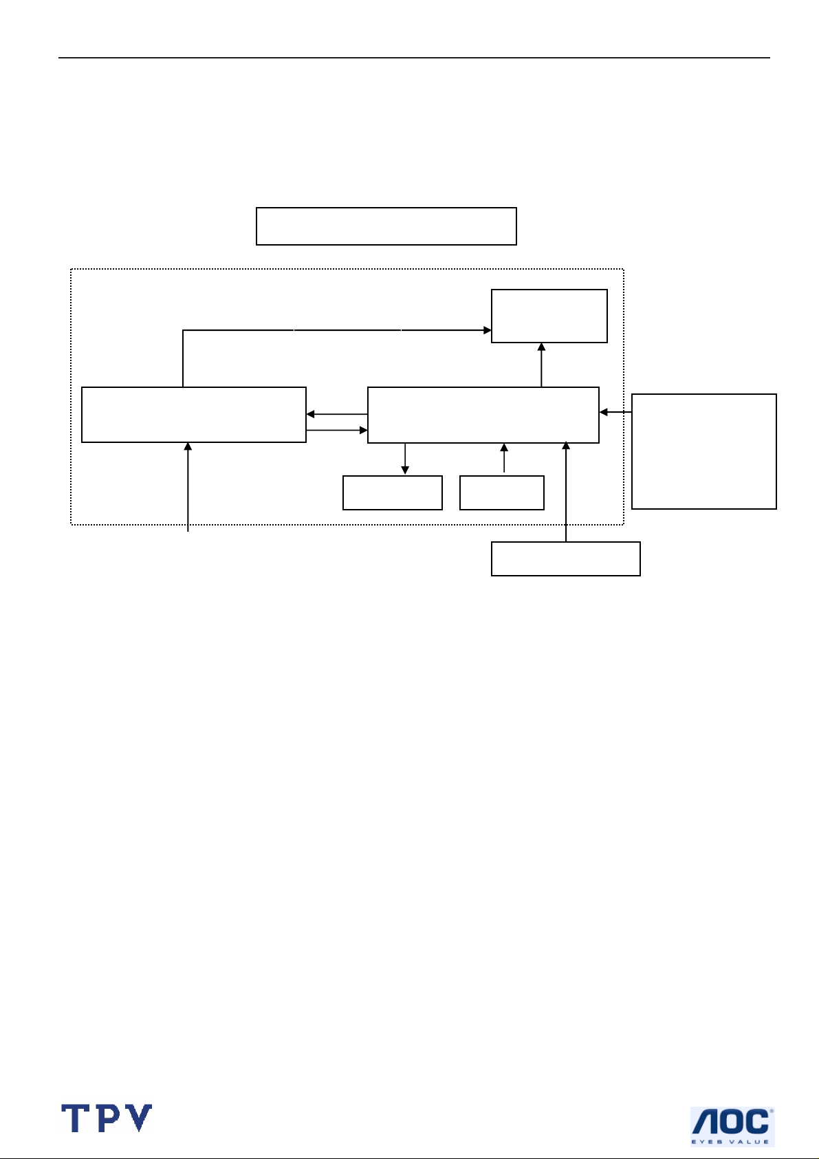
2. LCD Monitor Description
The LCD Monitor will contain main board, power board, key board and an audio board which house the flat panel
control logic, brightness control logic and DDC.
The power board will provide AC to DC Inverter voltage to drive the backlight of panel and the main board chips each
voltage.
Power Board
Include adapter and inverter)
AC-IN
110V-240
Monitor Block Diagram
CCFT Drive.
Main Board
Audio board
Key board
Flat Panel and
CCFL backlight
RS232 Connector
For white balance
adjustment in
factory mode
Video signal, DDC
HOST Computer
4
Page 5
17" LCD Color Monitor HP L1706
3. Operation Instructions
3.1 General Instructions
Press the power button to turn the monitor on or off. The other control buttons are located at front of the panel. By
changing these settings, the picture can be adjusted to your personal performance.
The power cord should be connected and insert to adaptor.
-
Connect the video cable from the monitor to the computer VGA card.
-
- Press the power button to turn on the monitor, the power indicator will light up to Green.
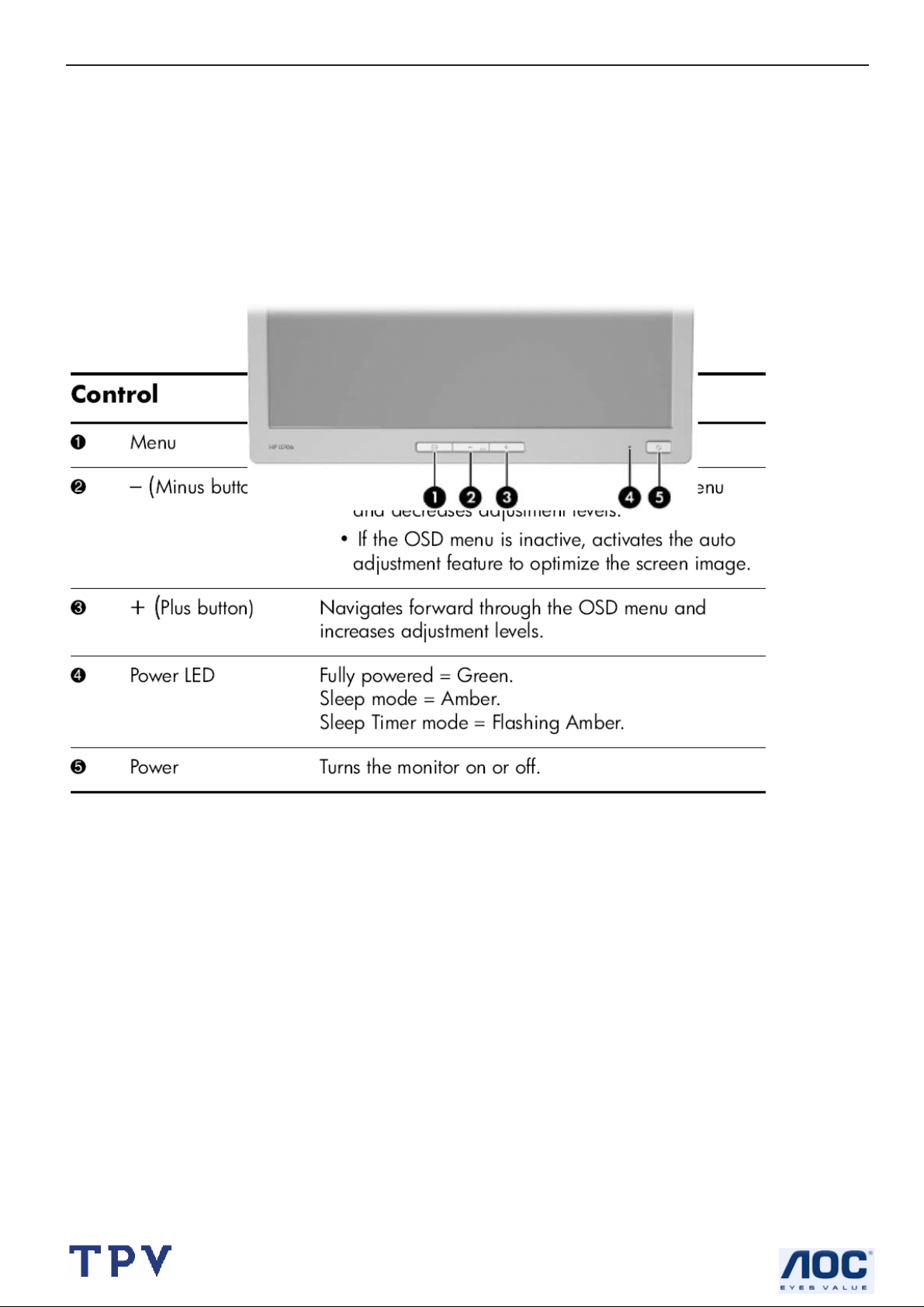
3.2 Control Buttons
5
Page 6

17" LCD Color Monitor HP L1706
3.3 Adjust the Picture
1.
2.
3.
4.
5.
6.
Brightness
Contrast Adjust the contrast
Image
Control
Color
Language Shows the language of the OSD window.
Management
Adjust the brightness.
Adjust the:
z Auto Adjustment: Adjusts the main settings a nd produces a stable, centered image.
z H-Position: horizontal position of the screen image.
z V-Position: vertical position of the screen image.
z Clock: frequency of the pixel clock to minimize vertical bar.
z Phase: phase value to minimize horizontal jitters.
z 9300K: recall 9300K color
z 6500K: recall 6500K color
z SRGB: recall SRGB color
z Custom Color: adjusts the color tint of white, and the red, green, and blue (RGB) mix
for colors.
z Power Saver: enable/disable power saving
z Power On Recall: enable/disable power recall
z Mode Display: enable/disable mode display
z Sleep Timer: set sleep timer
z Basic Menu: set to basic menu
7.
8.
9.
10.
OSD Control
Information Current setting, recommended setting, serial number, total hours, backlight hours, Exit.
Factory
Reset
Exit Exit the current OSD window.
OSD (on Screen Display) settings: adjusts the H/V position, timeout, On Screen Display
window.
Resets the display to original factory settings for color, brightness, phase, and cl ock.
6
Page 7
17" LCD Color Monitor HP L1706
4. Input/Output Specification
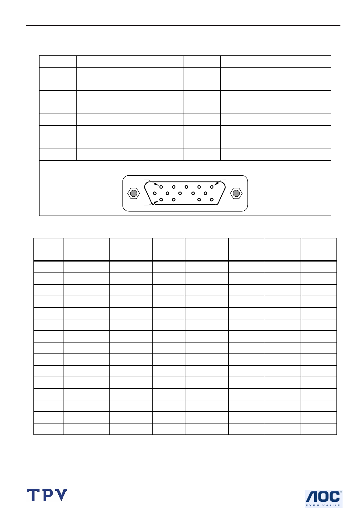
4.1 Input Signal Connector
Pin Signal Pin Signal
1 Red Video 9 +5 V (from PC)
2 Green Video 10 Ground
3 Blue Video 11 Ground
4 Ground 12 DDC-serial Data
5 Detect Cable 13 Horizontal Sync
6 Red GND 14 Vertical Sync
7 Green GND 15 DDC-serial Clock
8 Blue GND
PIN 1
PIN 11
4.2 Factory Preset Display Modes
Pixel
Preset
1 640 x 480 31.469 - 59.940 - 25.175 VGA
2 640 x 480 37.861 - 72.809 - 31.500 VESA
3 640 x 480 37.500 - 75.000 - 31.500 VESA
4 720 x 400 31.469 - 70.087 + 28.322 VGA
5 800 x 600 37.879 + 60.317 + 40.000 VESA
6 800 x 600 48.077 + 72.188 + 50.000 VESA
Format
Horz Freq
(KHz)
VGA connector layout
Horz
Polarity
Vert Freq
(Hz)
PIN 5
Vert
Polarity
Pixel Clk
(MHz) Source
7 800 x 600 46.875 + 75.000 + 49.500 VESA
8 832 x 624 49.726 ± 74.551 ± 57.284 MAC
9 1024 x 768 48.363 - 60.004 - 65.000 VESA
10 1024 x 768 56.476 - 70.069 - 75.000 VESA
11 1024 x 768 60.023 + 75.029 + 78.750 VESA
12 1152 x 870 68.68 - 75.06 - 100.000 Mac
13 1152 x 900 71.71 - 76.05 - 105.561 Sun
14 1280 x 1024 63.98 + 60.02 + 108.000 VESA
15 1280 x 1024 79.97 + 75.02 + 135.000 VESA
7
Page 8
17" LCD Color Monitor HP L1706
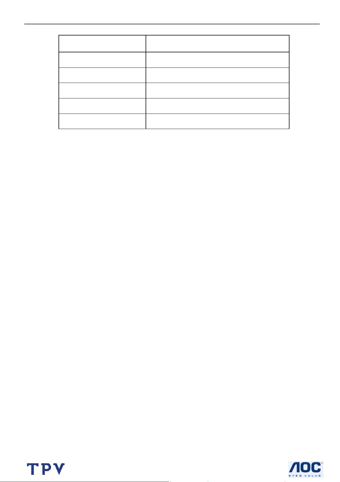
4.3 Power Supply Requirements
Parameter Range
AC Line Voltage range 100 to 240V
AC Line Frequency range 47 to 63 Hz
Peak surge Current < 55 A MAX AT 220VAC and cold starting
Leakage Current < 3.5 mA
Power Consumption
≤37W
8
Page 9

17" LCD Color Monitor HP L1706
5. Panel Specification
5.1 General Feature
ABSOLUTE MAXIMUM RATINGS
9
Page 10
17" LCD Color Monitor HP L1706
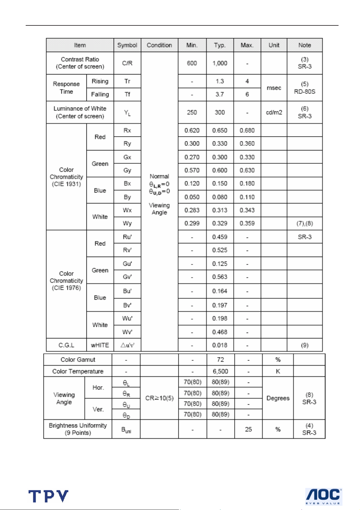
5.2 Optical Characteristics
10
Page 11
17" LCD Color Monitor HP L1706
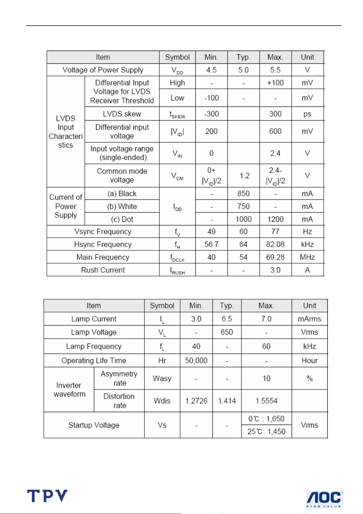
5.3 Parameter guide line for CCFL Inverter
TFT LCD Module:
Back Light Unit:
11
Page 12
17" LCD Color Monitor HP L1706
6. Block Diagram
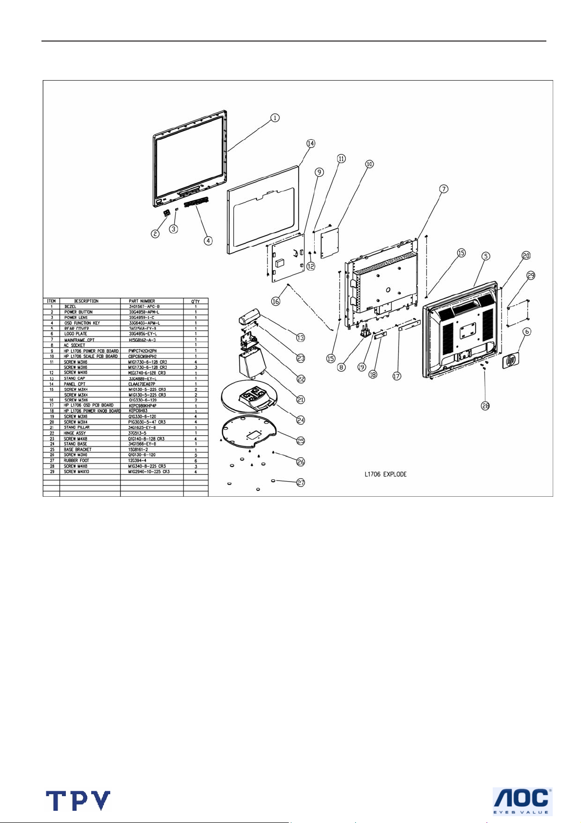
6.1 Monitor Exploded View
12
Page 13
17" LCD Color Monitor HP L1706
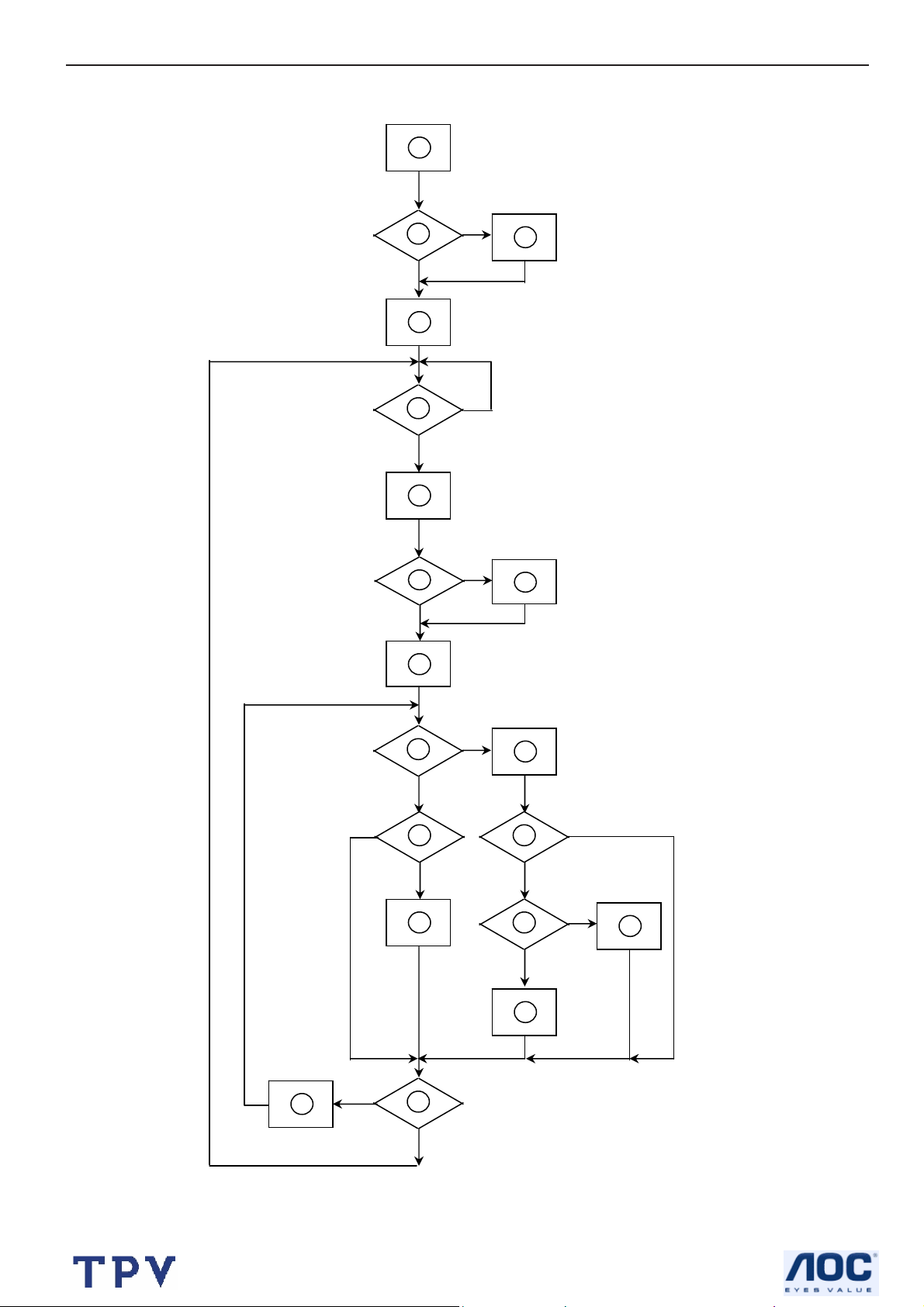
6.2 Software Flow Chart
1
Y
2
N
3
4
5
N
Y
6
N
7
8
Y
9
10
N
11
12
Y
13
N
N
Y
14
15
Y
N
16
Y
17
18
N
19
Y
13
Page 14
17" LCD Color Monitor HP L1706
REMARK:
1) MCU initialize.
2) Is the EEprom blank?
3) Program the EEprom by default values.
4) Get the PWM value of brightness from EEprom.
5) Is the power key pressed?
6) Clear all global flags.
7) Are the AUTO and SELECT keys pressed?
8) Enter factory mode.
9) Save the power key status into EEprom.
Turn on the LED and set it to green color.
Scalar initialize.
10) In standby mode?
11) Update the lifetime of back light.
12) Check the analog port, are they’re any signals coming?
13) Does the scalar send out an interrupt request?
14) Wake up the scalar.
15) Are there any signals coming from analog port?
16) Display "No connection Check Signal Cable" message. And go into standby mode after the message
disappear.
17) Program the scalar to be able to show the coming mode.
18) Process the OSD display.
19) Read the keyboard. Is the power key pressed?
14
Page 15

17" LCD Color Monitor HP L1706
(
Vsy
6.3 Electrical Block Diagram
6.3.1 Scalar Board
Control Interface
(KEYPAD)
OSD
MCU
U601)
EPR_SDA
EPR SCL
EEPROM
(U602)
Panel Interface
(CN503)
Scalar TSU16AK
(Include ADC, OSD)
(U401)
RXD
TXD
D-Sub Connector
R
G
B
(CN301)
Hsync,
nc
DB15_SDA
DB15 SCL
DDC_SDA
DDC SCL
EEPROM
(U301)
15
Page 16
17" LCD Color Monitor HP L1706
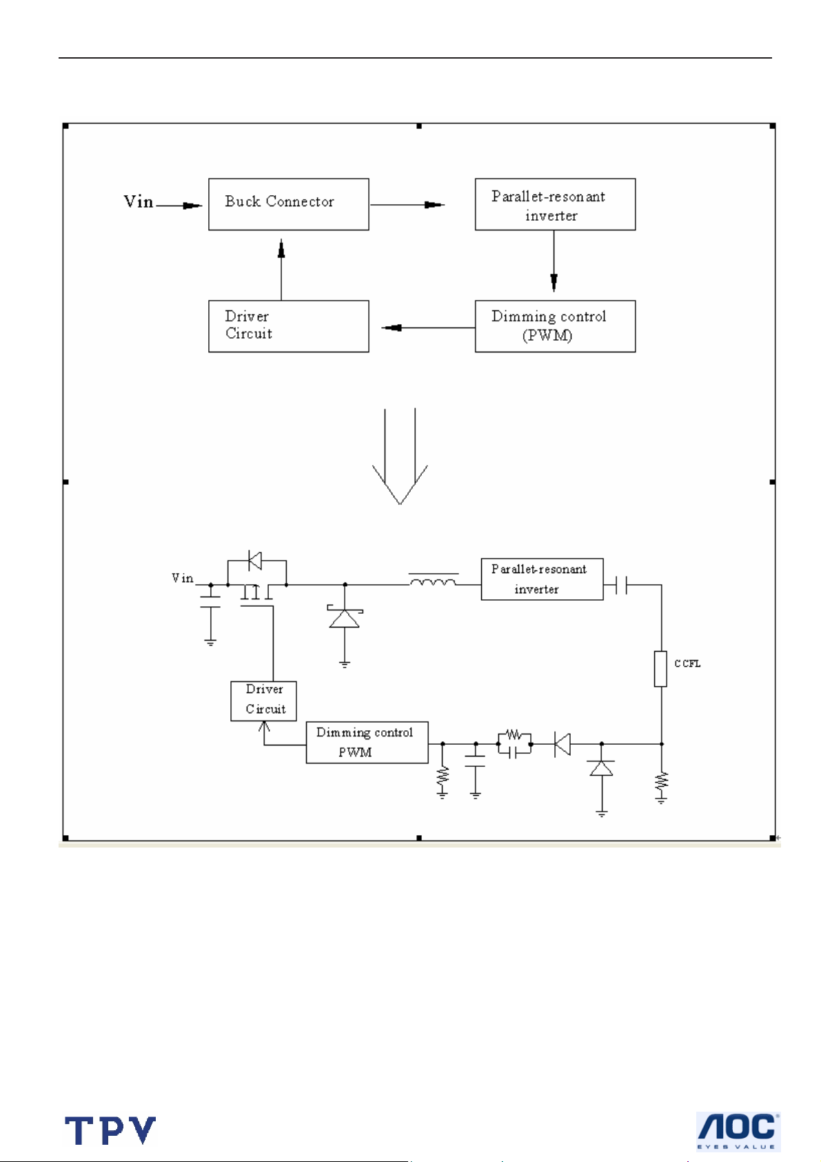
6.3.2 Inverter / Power Board
Inverter Block Diagram
16
Page 17
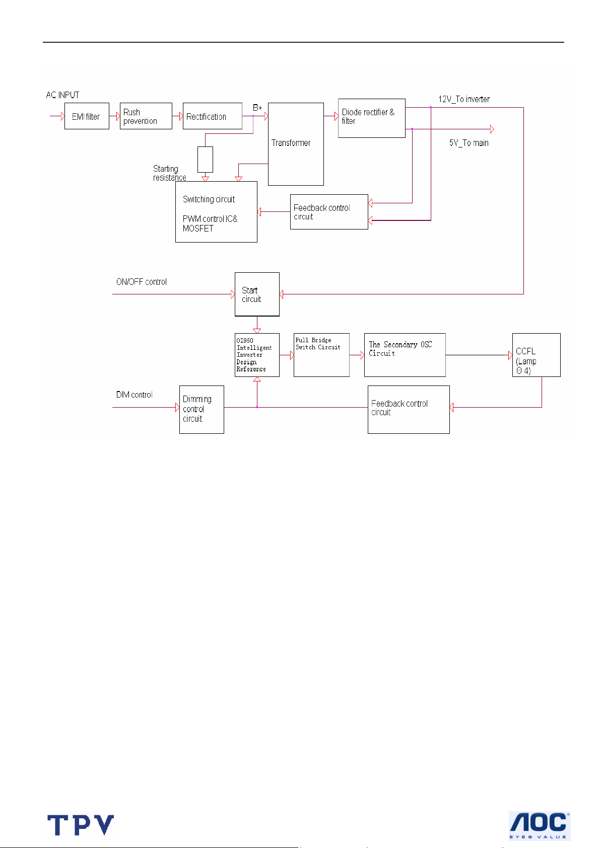
17" LCD Color Monitor HP L1706
Power Block Diagram
17
Page 18

17" LCD Color Monitor HP L1706
7. Schematic
7.1 Main Board
SCHEMATIC
VCPU
VAA4
VAA3
VAA2
VCC3.3
VCC1.8
VAA1
VCPU
B1
TXD
RXD
DDC_DAT
ST_DET1 HSYNC
DDC_WP
3.INPUT
B3
DDC_WP
ST_DET1
DDC_CLK
DDC_DAT
RXD
TXD
VCPU
onPANEL_5V/3.3V
onBACKLITE
onPANEL_12V
6.MCU
B4
onPanel_12V
onBACKLITE
onPanel_5V/3.3V
VCPU
VCC3.3
AdjBACKLITE
VCC1.8
VAA1
VAA2
VAA3
VAA4
2.POWER
GNDR
GNDG
SOGDDC_CLK
GNDB
VSYNC
CSZ
SCL
SDA
HWRESET
AD0
AD1
AD2
AD3
VLCD_12V
VLCD
FOR
L1506/1706
VLCD
B2
RIN
GNDR
GIN
GNDG
SOG
BIN
GNDB
HSYNC
VSYNC
CSZ
SCL
SDA
HWRESET
INT
AD0
AD1
AD2
AD3
AdjBACKLITE
4.SCALER
RIN
GIN
BIN
INT
VLCD_12V
HPQ2005
VCC1.8
VCC3.3
VAA1
VAA2
VAA3
VAA4
PA[0..9]
PB[0..11]
GA[0..3]
BA[0..5]
RB[0..5]
GB[0..5]
ESP
OSP
GPO[0..4]
VCC1.8
VAA2
VAA1
VCC3.3
PA[0..9]
PB[0..11]
GA[0..3]
BA[0..5]
RB[0..5]
GB[0..5]
ESP
OSP
GPO[0..4]
Title
Size Document Number Rev
B
Date: Sheet
VAA3
VAA4
B5
PA[0..9]
PB[0..11]
GA[0..3]
BA[0..5]
RB[0..5]
GB[0..5]
ESP
GPO[0..4]
5.PANEL INTERFACE
VLCD
VLCD_12VOSP
HPQ2005-L1506/1706
TOP
VLCD
VLCD_12V
17Wednesday, June 01, 2005
A
of
18
Page 19

17" LCD Color Monitor HP L1706
+
C209
47uF/16V
C214
0.1uF
VCC5V+
+
D202
DIODE
C210
0.1uF
TO-263
U202
3
1
AIC1084-33M
VIN
ADJ
TO-252
U201
AZ1117D-1.8
3 2
VI VO
2
VOUT
47uF/16V
1
C215
GND
+
C211
47uF/16V
C216
0.1uF
+
VCC3.3
VCC1.8
VAA1
VAA2
VAA3
VAA4
C212
0.1uF
FB202
600 OHM
VCC1.8 4
VCC3.3 4
VCPU 6
VAA1 4
VAA2 4
VAA3 4
VAA4 4
VCC5V
VCC12V
CN201
GND
GND
VCC12V
GND
VCC5V
GND
1
3
5
7
9
11
CONN
Brightness
R205 4.7K 1/16W
AdjBACKLITE4
onPanel_5V/3.3V6
1
VCC12V
R218
NC
R207 4.7K 1/16W
C207
0.1uF
VCC5V
32
VCC3.3
2
4
6
8
10
12
R203
1K 1/16W
Q202
PMBS3904
VCC5V
R219
NC
1
ON_OFF
DIM
VCC12V
GND
VCC5V
GND
R204
10K 1/16W
R208
10K 1/16W
R217 51K 1/16W
32
Q204
PMBS3904
220uF/25V
C219
0.1uF
C206
1uF
C202
R201 4.7K 1/16W
D201 DIODE SCHOTTKY
C203
+
0.1uF
VLCD
Q203
AO3401
+
C208
10uF/16V
FB201
600
C204
+
220uF/25V
VLCD 5
VCC5V
VCC5V+
VCC5V
VCPU
C205
0.1uF
R209 for L1706
NC
R211
10K 1/16W
C201
0.1uF
VCPU 6
VCC3.3
R210 for L1506
0 1/16W
R202
10K 1/16W
32
Q201
PMBS3904
VCC12V
R212 4.7K 1/16W
1
R220 NC
0 1/16W
onBACKLITE 6
VCC5V+
C213
47uF/16V
VCC12V
R215 NC
10K 1/16W
onPanel_12V6
NC R214
4.7K 1/16W
C217 NC
0.1uF
1
32
Q205
PMBS3904 NC
VLCD_12V
VLCD_12V 5
Q206
NC
+
10uF/16V
C218 NC
VCC12V
R216 NC
4.7K 1/16W
H1
678
9
123
123
5
678
5
4
4
H8D3.5-2LX
9
H2
678
9
123
123
5
678
5
4
4
H8D3.5-2LX
9
H3
678
9
123
123
5
678
5
4
4
H8D3.5-2LX
9
H4
678
9
123
123
5
678
5
4
4
H8D3.5-2LX
Title
Size Document Number Rev
B
Date: Sheet
HPQ2005-L1506/1706
POWER
of
27Wednesday, June 01, 2005
A
9
19
Page 20

17" LCD Color Monitor HP L1706
R
D323
MLL5232B 5.6V
D322
MLL5232B 5.6V
11
12
13
14
15
HSI
VSI
D319
MLL5232B 5.6V
CN301
DB15
RXD 6
1
6
2
7
3
8
4
9
PC5V
5
10
VGA_CON
D320
MLL5232B 5.6V
D321
MLL5232B 5.6V
TXD 6
3
D301
BAV99
C315
2
0.1uF
FB304 200 OHM
R312 100 1/16W
D318
MLL5232B 5.6V
3
C316
1
2
0.1uF
D302
BAV99
1
FB301 0 1/16W
FB302 0 1/16W
FB303 0 1/16W
3
D303
BAV99
C317
1
2
0.1uF
R313
2.2K 1/16W
75 1/16W
VCC5V
CLK_DDC
DAT_DDC
R325
C311
68pF
C301
NC
R314
2.2K 1/16W
R326
C302
NC
75 1/16W
R327
C312
220pF
C303
NC
75 1/16W
R301 33 1/16W
R302 33 1/16W
R303 33 1/16W
R304 470 1/16W
R305 68 1/16W
R306 68 1/16W
R307 68 1/16W
VCC5V
R308
10K 1/16W
R309 100 1/16W
R310 1K 1/16W
R311 1K 1/16W
D317
MLL5232B 5.6V
C304 0.047uF
C305 0.047uF
C306 0.047uF
C307 0.001uF
C308 0.047uF
C309 0.047uF
C310 0.047uF
RIN 4
GIN 4
BIN 4
SOG 4
GNDR 4
GNDG 4
GNDB 4
ST_DET1 6
HSYNC 4
VSYNC 4
R315 22 1/16W
R316 22 1/16W
DDC_DAT6
DDC_CLK6
R317
4.7K 1/16W
R318
4. 7K 1/16W
VCC5V
2
R328
4.7K 1/16W
PC5V
3
1
D304
BAV70
U301
8
VCC
7
WP
6
SCL
AT24C02N-10SC
C313
0.22uF
1
A0
2
A1
3
A2
45
GNDSDA
modify ddc_wp circuit
DDC_WP6
R319
22K 1/16W
R329
10K 1/16W
CE
Q301
B
PMBS3904
C314
0.1uF/16V
Title
Size Document Number
B
Date: Sheet of
HPQ2005-L1506/1706
INPUT
37Wednesday, June 01, 2005
20
Page 21

17" LCD Color Monitor HP L1706
FB401
600 OHM
C405
10uF/16V
VPO
+
PA[0..9] 5
GA[0..3] 5
BA[0..5] 5
RB[0..5] 5
GB[0..5] 5
PB[0..11] 5
ESP 5
OSP 5
GPO[0..4] 5
C406
0.1uF
C407
0.1uF
C408
0.1uF
C409
0.1uF
C410
0.1uF
C411
0.1uF
VCC1.8
FB402
VDD
VCC1.82
C412
C413
0.1uF
0.1uF
VAA12
VAA22
VAA32
VAA42
Title
Size Document Number Rev
B
Date: Sheet
HPQ2005-L1506/1706
VAA1
VAA2
VAA3
VAA4
SCALER
600 OHM
C414
10uF/16V
FB403
600 OHM
10uF/16V
FB404
600 OHM
10uF/16V
FB405
600 OHM
10uF/16V
FB406
600 OHM
10uF/16V
VAD
C419
VPLL
C422
VDVI
C424
VDPLL
C427
47Wednesday, June 01, 2005
+
C418
C417
C416
+
+
+
+
C415
0.1uF
C420
0.1uF
C423
0.1uF
C425
0.1uF
C428
0.1uF
0.1uF
C421
0.1uF
C426
0.1uF
0.1uF
0.1uF
A
of
Direct Bus
3-WIRE
VCC3.3
VCC3.32
VAD
VPLL
VDPLL
53
AVDD_DVI
AVDD_PLL
AVSS_PLL
AVSS_DVI
AVSS_DVI
39
4210208595
VPO
11218494104
VDDP
VDDP
VDDP
VDDP
GNDP
GNDP
AVSS_DVI
48
VDVI
55
35
45351
65
U401
TSU17AK
AVDD
AVDD
C401
0.1uF
X401
63
RIN0
62
RIN0M
60
GIN0
59
GIN0M
61
SOGIN0
58
BIN0
57
BIN0M
37
HSYNC0
38
VSYNC0
29
DDC1_CLK/GPO8
28
DDC1_DAT/GPO7
40
R+
41
R-
43
G+
44
G-
46
B+
47
B-
49
CK+
50
CK-
52
REXT
66
REFP
67
REFM
6
BUS TYPE
69
CSZ
71
SCL
70
SDA
32
HWRESETZ
72
INT
30
AD0
77
AD1
78
AD2
31
AD3
73
PWM0
74
PWM1
33
XIN
34
XOUT
BYPASS
AVSS_LPLL
68
AVSS
56
AVSS
64
AVSS
AVDD_MPLL
36254
AVDD_DVI
AVSS_MPLL
RIN3
GNDR3
GIN3
GNDG3
SOG3
BIN3
GNDB3
HSYNC3
VSYNC3
VDVI
R402
4.7K 1/16W
R401
NC
R403 390 1/16W
CSZ6
SCL6
SDA6
HWRESET6
AdjBACKLITE2
C402 22pF
14.318MHz
C403 22pF
C404 0.1uF
INT6
R402
R401
4.7K
NC
4.7K
AD06
AD16
AD26
AD36
NC
VCC3.3
VDD
114
126188797117
VDDP
VDDP
VDDP
VDDC
VDDC
VDDC
LVA3p/GA3P
LVA3M/GA3N
LVACKP/NC
LVACKM/NC
LVA2P/RA1P
LVA2M/RA1N
LVA1P/RA2P
LVA1MRA2N
LVA0P/RA3P
LVA0M/RA3N
NC/RB1P
NC/RB1N
NC/RB2P
NC/RB2N
NC/RB3P
NC/RB3N
NC/GB1P
NC/GB1N
NC/GB2P
NC/GB2N
NC/GB3P
NC/GB3N
LVB3P/CLKAP
LVB3M/CLKAN
LVBCKMP/NC/CLKBP
LVBCKP/NC/CLKBN
LVB2P/NC
LVB2M/NC
LVB1P/NC/BB1P
LVB1M/NC/BB1N
LVB0P/NC/BB2P
LVB0M/NC/BB2N
NC/BB3P
NC/BB3N
NC/ESP
GNDP
GNDP
GNDP
GNDP
GNDC
GNDP
115
1271986
105
VDDC
GA1P
GA1N
GA2P
GA2N
BA1P
BA1N
BA2P
BA2N
BA3P
BA3N
GPO0
GPO1
GPO2
GPO3
GPO4
GNDC
96
OSP
GNDC
116
GNDC
PA0
102
PA1
103
PA2
106
PA3
107
PA4
108
PA5
109
PA6
110
PA7
111
PA8
112
PA9
113
GA0
98
GA1
99
GA2
100
GA3
101
BA0
88
BA1
89
BA2
90
BA3
91
BA4
92
BA5
93
RB0
16
RB1
17
RB2
22
RB3
23
RB4
24
RB5
25
GB0
8
GB1
9
GB2
12
GB3
13
GB4
14
GB5
15
PB0
118
PB1
119
PB2
120
PB3
121
PB4
122
PB5
123
PB6
124
PB7
125
PB8
128
PB9
1
PB10
4
PB11
5
75
76
83
82
81
80
79
GPO0
GPO1
GPO2
GPO3
GPO4
PA[0..9]
GA[0..3]
BA[0..5]
RB[0..5]
GB[0..5]
PB[0..11]
ESP
OSP
GPO[0..4]
21
Page 22

17" LCD Color Monitor HP L1706
CN502
1
2
3
4
5
6
7
8
9
10
11
12
13
14
15
16
17
18
19
20
21
22
23
24
25
26
27
28
29
30
CONN
LVB0M
LVB1M
LVB2M
LVBCKM
LVB3M
LVA0M
LVA1M
LVA2M
LVACKM
LVA3M
C509
22uF/16V
RXO0RXO1RXO2RXOCRXO3RXE0RXE1RXE2RXECRXE3-
+
CN503
LVB0P
RXO0+
CONN
C510
0.1uF
VLCD
2
4
6
8
10
12
14
16
18
20
22
24
RXO1+
RXO2+
RXOC+
RXO3+
RXE0+
RXE1+
RXE2+
RXEC+
RXE3+
VLCD 2
LVB1P
LVB2P
LVBCKP
LVB3P
LVA0P
LVA1P
LVA2P
LVACKP
LVA3P
C511
0.1uF
1
3
5
7
9
11
13
15
17
19
21
23
R513
CN501
1
2
3
4
5
6
7
8
9
10
11
12
13
14
15
16
17
18
19
20
21
22
23
24
25
26
27
28
29
30
31
32
33
34
35
36
37
38
39
40
41
42
43
44
45
46
47
48
49
50
CONN
R514
5V
0R
NC
NC
NC
NC
NC
12V
0R
NC
NC
NC
RB3N
RB3P
RB2N
RB2P
RB1N
RB1P
GB3N
GB3P
GB2N
GB2P
GB1N
GB1P
CLKBN
CLKBP
BB3N
BB3P
BB2N
BB2P
BB1N
BB1P
BG0N
BG0P
BG1N
BG1P
BG2N
BG2P
BCLKN
BCLKP
BR0N
BR0P
BR1N
BR1P
BR2N
BR2P
PA[0..9]4
PB[0..11]4
RB[0..5]4
GB[0..5]4
PB[0..11]4
GPO[0..4]4
PA[0..9]
PB[0..11]
RB[0..5]
GB[0..5]
PB[0..11]
GPO[0..4]
RB0
RB1
RB2
RB3
RB4
RB5
GB0
GB1
GB2
GB3
GB4
GB5
PB6
PB7
PB8
PB9
PB10
PB11
PB3
PB2
PA0
PA1
PA2
PA3
PA4
PA5
PA6
PA7
PA8
PA9
PB0
PB1
PB2
PB3
PB4
PB5
PB6
PB7
PB8
PB9
GPO0
GPO1
GPO2
GPO3
GPO4
LVA3P
LVA3M
LVACKP
LVACKM
LVA2P
LVA2M
LVA1P
LVA1M
LVA0P
LVA0M
LVB3P
LVB3M
LVBCKP
LVBCKM
LVB2P
LVB2M
LVB1P
LVB1M
LVB0P
LVB0M
RB1P
RB1N
RB2P
RB2N
RB3P
RB3N
GB1P
GB1N
GB2P
GB2N
GB3P
GB3N
BB1P
BB1N
BB2P
BB2N
BB3P
BB3N
CLKBN
CLKBP
R501 0 1/16W
R502 0 1/16W
R503 0 1/16W
R504 0 1/16W
R505 0 1/16W
FB0N
RA3N
FB0P
RA3P
FB1N
RA2N
FB1P
RA2P
RA1N
FB2N
RA1P
FB2P
GA3N
FG0N
FG0P
GA3P
FG1N
GA2N
FG1P
GA2P
FG2N
GA1N
FG2P
GA1P
FCLKN
CLKAN
FCLKP
CLKAP
FR0N
BA3N
FR0P
R508 0 1/16W
R510 0 1/16W
R512 0 1/16W
R510
5V
0R
NC
3.3V
0R
3.3V
0R
3.3V
0R
BA3P
BA2N
BA2P
BA1N
BA1P
GPOO1
GPOO0
GPOO3
GPOO2
GPOO4
R511
FR1N
FR1P
FR2N
FR2P
STH
LP
POL
HMS
CLKV
STV
OE
R509
NC
R511
NC
R513
R514
NC
NC
R512
5V
0R
NC
12V
0R
NC
NC
NC
12V
NC
0R
NC
NC
PA[0..9]4
GA[0..3]4
PA[0..9]4
BA[0..5]4
PB[0..11]4
PA[0..9]
GA[0..3]
PA[0..9]
BA[0..5]
PB[0..11]
PA4
PA5
PA6
PA7
PA8
PA9
GA0
GA1
GA2
GA3
PA0
PA1
BA0
BA1
BA2
BA3
BA4
BA5
PB0
PB1
GPOO0
GPOO1
GPOO2
GPOO3
GPOO4
RA1P
RA1N
RA2P
RA2N
RA3P
RA3N
GA1P
GA1N
GA2P
GA2N
GA3P
GA3N
BA1P
BA1N
BA2P
BA2N
BA3P
BA3N
CLKAP
CLKAN
OSP4
ESP4
VLCD2
VLCD_12V
VLCD_12V2
AU 17
QDI 17
CPT 17
INNOLUX 15
HannStar 15
CPT 15
LG 15
VLCD
C512
22uF/16V
OSP
R506 0 1/16W
R507 NC
ESP
C508
+
0.1uF
R508
NC
3.3V
0R
3.3V
0R
3.3V
0R
3.3V
0R
R509
NC
12V
0R
NC
NC
NC
22
Title
HPQ2005-L1506/1706
Size Document Number Rev
B
Date: Sheet
PANEL INTERFACE
57Wednesday, June 01, 2005
of
A
Page 23
17" LCD Color Monitor HP L1706
VCPU
VCPU2
123
4
123
VCPU
Reset
Circuit
U603 MAX810STR (NC)
23
RSTVCC
GND
1
C605
U602
0.22uF
1
A0
2
A1
3
A2
4 5
GND SDA
24C16
R643 NC
VCC
WP
SCL
8
7
6
D601
LL4148
VCPU
R605 10K 1/16W
R655 10K 1/16W
R604 10K 1/16W
R641 0 1/16W
R642
NC
C603
10uF/16V
+
R603
10K 1/16W
R601
10K 1/16W
C602
22pF
Y601
24MHz
C604
22pF
INT4
R609 100 1/16W
R646 NC
R608 100 1/16W
R602
C601
0.1uF
10K 1/16W
35
21
20
10
12
14
33
32
17
2
3
4
5
6
7
8
9
U601
EA/VP
XTAL1
XTAL2
RESET
P4.3
INT0/P3.2
ALE/P
PSEN
T1/P3.5
P1.0
P1.1
P1.2
P1.3
P1.4
P1.5
P1.6
P1.7
W78E65P-40
VSS VCC
22 44
P0.0
P0.1
P0.2
P0.3
P0.4
P0.5
P0.6
P0.7
P2.0
P2.1
P2.2
P2.3
P2.4
P2.5
P2.6
P2.7
T0/P3.4
INT1/P3.3
P3.6/WR
P3.7/RD
P3.1/TXD
P3.0/RXD
RP601
10K 1/16W
43
42
41
40
39
38
37
36
24
25
26
27
28
29
30
31
16
15
18
19
13
11
4
5
RP602
10K 1/16W
876
5
876
R610 22 1/16W
R611 22 1/16W
R634 NC
R635 NC
10K 1/16W
R606
10K 1/16W
R607
10K 1/16W
RP603
4
5
RP604
10K 1/16W
876
5
876
R644
10K 1/16W
LED_G
R636
100 1/16W
POWER
MENU
RIGHT
LEFT
LED_O
AD0 4
AD1 4
AD2 4
AD3 4
CSZ 4
SCL 4
SDA 4
HWRESET 4
onPANEL_5V/3.3V 2
onBACKLITE 2
DDC_WP 3
DDC_DAT 3
DDC_CLK 3
TXD 3
RXD 3
123
4
123
LED_O
4.7K 1/16W
R629
MPU
C613
0.1uF
67Wednesday, June 01, 2005
of
A
R613
10K 1/16W
ST_DET13
onPANEL_12V2
VCPU
R628
470 1/16W
Q603
B
PMBS3906
C E
POWER
MENU
LEFT
RIGHT
R645 10K 1/16W
4.7K 1/16W
LED_G
R621 1K 1/16W
R623 1K 1/16W
R624 1K 1/16W
R620 1K 1/16W
R616
VCPU
VCPU
R617
470 1/16W
Q601
B
PMBS3906
C E
C607
C609
C610
0.001uF
0.001uF
0.001uF
LED_GREEN
LED_ORANGE
KEY_ONOFF
KEY_MENU
KEY_LEFT/AUTO
KEY_RIGHT
C606
0.001uF
1
2
3
4
5
6
7
8
CN402
CONN
Title
Size Document Number Rev
Date: Sheet
HPQ2005-L1506/1706
B
23
Page 24

17" LCD Color Monitor HP L1706
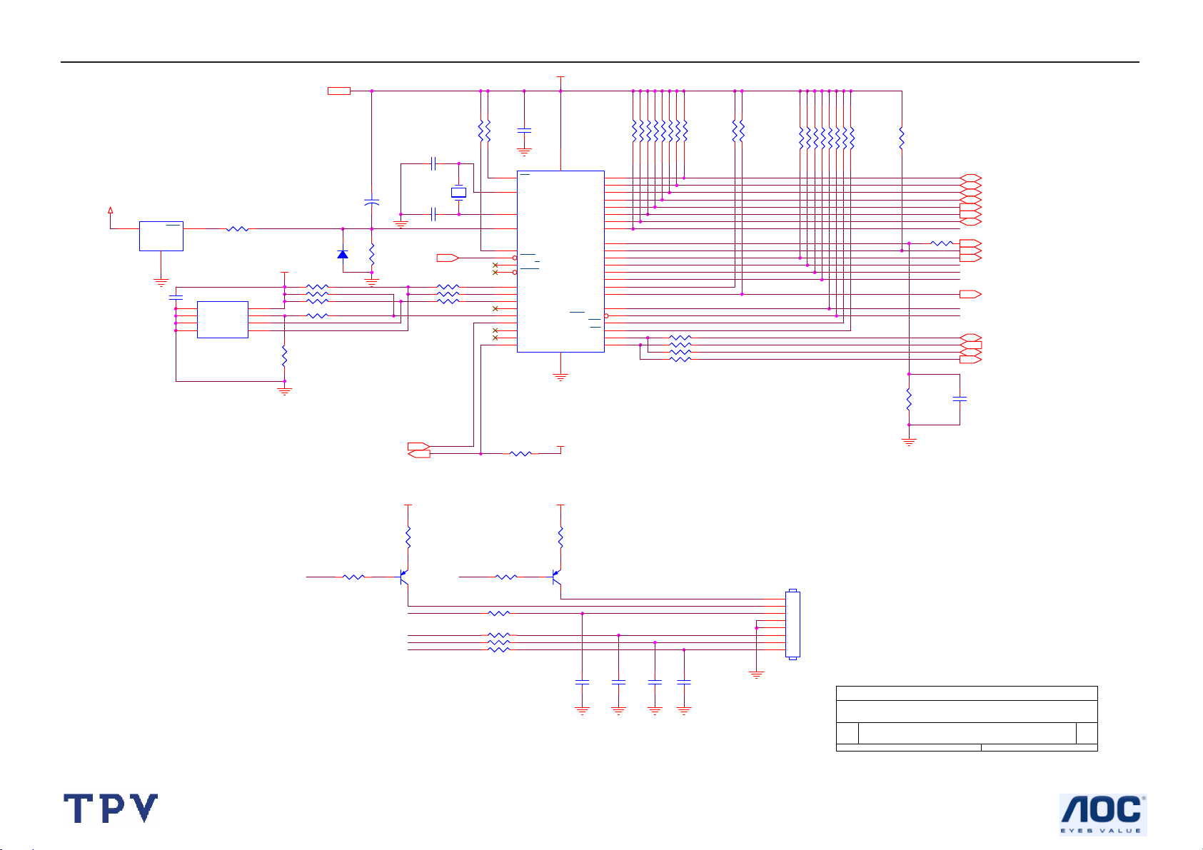
7.2 Power Board
24
Page 25

17" LCD Color Monitor HP L1706
25
Page 26

17" LCD Color Monitor HP L1706
8. PCB Layout
8.1 Main Board
26
Page 27

17" LCD Color Monitor HP L1706
27
Page 28

17" LCD Color Monitor HP L1706
8.2 Power Board
28
Page 29

17" LCD Color Monitor HP L1706
29
Page 30

17" LCD Color Monitor HP L1706
30
Page 31

17" LCD Color Monitor HP L1706
8.3 Key Board
31
Page 32

17" LCD Color Monitor HP L1706
9. Maintainability
9.1 Equipments and Tools Requirement
1. Multi-meter.
2. Oscilloscope.
3. Pattern Generator.
4. DDC Tool with an IBM Compatible Computer.
5. Alignment Tool.
6. LCD Color Analyzer.
7. Service Manual.
8. User Manual.
32
Page 33

17" LCD Color Monitor HP L1706
9.2 Trouble Shooting
9.2.1 Main Board
No power
Press power key and look if the
picture is normal
Please reinsert and make sure the
AC of 100-240 is normal
Measure CN201 PIN5/6=12V?
Measure CN201 PIN7/8=5V?
No power
NG
OK
OK
NG
NG
Reinsert or check the
power section
Check power section
Y601 oscillate waveforms
are normal
OK
Replace U601
NG
Replace Y601
NG
Replace U401
33
Page 34

17" LCD Color Monitor HP L1706
No picture (LED orange)
No picture
Key is under control?
NG
Y601 oscillate waveforms are
normal
X401 oscillate waveforms are
normal
OK
NG
OK
Replace U601
Replace Y601
OK
NG
Replace X401
NG
Check if the sync signal from
Replace U401
computer is output and video cable
is connected normally
NG
Input the sync signal of computer, o r
OK
change the cable
Replace U401
34
Page 35

17" LCD Color Monitor HP L1706
Panel Power Circuit
Check Correspondent
component.
Measure Q204 base is high level?
NG
OK
Check Q204 and Q203 are broken
or CN503 /CN501 solder?
NG
OK
Replace PANEL
Y601 oscillate waveforms are normal
OK
Replace U601
Replace U401
NG
Replace Y601
NG
35
Page 36

17" LCD Color Monitor HP L1706
9.2.2 Power Board
1. No Power
No power
Check AC line volt 110V or 220V
OK
NG
Check AC line
Check the voltage of C905(+)
OK
NG
Check F901, bridge rectified circuit
Check start voltage for the pin3 of IC901
OK
NG
Check R909, R910,IC931
Check the auxiliary voltage is between 10V-16V
NG
OK
Check IC901,T901
Check D902, D904, IC902
NG
Check D906, IC904
Check IC902,IC903
Check Q910…OLP circuit
OK
Check D920 D921 ZD920…
36
Page 37

17" LCD Color Monitor HP L1706
2. W/LED No Backlight
Check IC801 pin5=12V voltage PIN3>3V
NG
OK
Change Q806 or Q807 or Q812
Preset at 2V to PIN4 of IC801 and Connect PIN1 to GND
Check the pin15 of IC801 have saw tooth wave
OK
NG
Change IC801
Check Q808、Q809
OK
NG
Change Q808、Q809
Open D809, Check IC801 PIN2<2V
OK
NG
Check OVP loop circuit
Check IC801 PIN9≠0V
OK
NG
Check D801 FB loop circuit
Check open protection circuit
Check connecter & lamp
37
Page 38

17" LCD Color Monitor HP L1706
9.2.3 Key Board
OSD is unstable or not working
Is Key Pad Board connecting normally?
NG
Connect Key Pad Board
Is Button Switch normally?
OK
NG
Replace Button Switch
OK
Is Key Pad Board Normally?
NG
Replace Key Pad Board
OK
Check Main Board
38
Page 39

17" LCD Color Monitor HP L1706
10. White- Balance, Luminance Adjustment
Approximately 30 minutes should be allowed for warm up before proceeding White-Balance adju stment.
1. How to do the Chroma-7120 MEM .Channel setting
A. Reference to chroma 7120 user guide
B. Use “ SC” key and “ NEXT” key to modify xyY value and use “ID” key to modify the TEXT description
Following is the procedure to do white-balance adjust
2. Setting the color temp. You want
A. 9300 color: 9300 color temp. parameter is x = 283 ±20, y = 297 ±20, Y > 180 cd/m2 ,
B. sRGB color: sRGB color temp. parameter is x = 313±20, y = 329 ±20, Y>200 cd/m2)
C. 6500K color: Don’t adjust, Custom requires.
3. Into factory mode of HP L1706
A. Press DOWN button during 2 seconds along with press Power button will activate the factory mode, then
MCU will do AUTO LEVEL automatically. Meanwhil e press MENU the OSD screen will located at THE
LEFT TOP OF PANEL.
4. Bias adjustment:
Set the Contrast
Adjust the Brightness
5. Gain adjustment :
Move cursor to “-F-” and press MENU key
A. Adjust 9300k color-temperature
1. Switch the Chroma-7120 to 9300k channel.
2. The chroma 7120 will show x = 283±20, y = 297 ±20, Y>180 cd/m2
3. Switch the chroma-720 to RGB MODE (with press “MODE” button to change )
4. Adjust the RED of color 9300K on factory window until chroma 7120 indicator reached the value R=100
5. Adjust the GREEN of color 9300K on factory window until chroma 7120 indicator rea ched the value G=100
6. Adjust the BLUE of color 9300K on factory win dow until chroma 7120 in dicator reached the value B=100
7. Repeat above procedure ( item 4,5,6) until chroma 7120 RGB value meet the tolerance =100±2
B. Adjust sRGB color-temperature
1. Switch the chroma-7120 to sRGB channel.
2. The chroma 7120 will show x = 313 ±20, y = 329 ±20, Y = 210 ±20 cd/m2
3. Switch the chroma 7120 l to RGB MODE ( with press “MODE” button to change )
to 80
to 90.
4. Adjust the RED of color sRGB on fact ory window until chroma 7120 indicator reached the value R=100
5. Adjust the GREEN of color sRGB on f actory window until chroma 7120 indicator reached the value G=100
6. Adjust the BLUE of color sRGB on factory win dow until chroma 7120 indicator reached the value B=100
7. Repeat above procedure ( item 4,5,6) until chroma 7120 RGB value meet the tolerance =100±2
C. Press reset key and Turn the Powe r-button “off to on” to quit from factory mode.
39
Page 40

17" LCD Color Monitor HP L1706
11. BOM List
T76SM4DTAKHPNE / T76SM4DTAKHANE / T76SM4DDAKHANE
Location Part No. Description
52G 1186 SMALL TAPE
CBPC6SM4HPH MAIN BOARD FOR 17
KEPC980KHP4P KEY BOARD
KEPC980KHP5P KEY BOARD FOR POWER
PWPC1742SEH1P POWER BOARD
11G 178 1 SPACER SUPPORT
15G8162 1 MAIN FRAME
33G4856 EY L LOGO PLATE
33G4889 EY L STAND CAP
34G1568 EY B REAR COVER
40G 58169015A TAIWAN LABEL
40G 58169016A TCO03 LABEL
41G780069094B QSG
44G3760 1 EPS(L)
44G3760 2 EPS(R)
52G 1185 MIDDLE TAPE
52G6022 1500 SMALL TAPE
89G1738GAAE01 SIGNAL CABLE
95G8014 8 30 HARNESS 160MM 8P-8P
E095 95G8018 3508 WIRE HARNESS
M1G 130 5225 CR3 SCREW
M1G 340 8225 CR3 SCREW 4*8mm
M1G1730 6128 CR3 SCREW M3x6
M1G1730 6128 CR3 SCREW M3x6
M1G1740 6128 CR3 SCREW
M1G2940 10225 CR3 SCREW
P1G3030 5 47 CR3 SCREW
Q1G 330 6120 SCREW M3X6mm
Q1G 330 6120 SCREW M3X6mm
Q1G 330 6120 SCREW M3X6mm
705G 780 87 01 AC SOCKET ASS'Y
705G780KF34 36 BEZEL ASS'Y
705G780KP34 10 STAND ASS'Y
E750L 750GLS70U3132Z000H PANEL LTM170EU-L31 0ST
H40G 170690 2E RATING LABEL
H40G 17N690 5A RATING LABEL
H40G581H690 2A CARTON LABEL
40
Page 41

17" LCD Color Monitor HP L1706
H41G160069035E DOC KIT APD(391904-376)
H41G780069099C SCREEN FLY (311618-007
H41G7800690B12 RTF CARD(407430-004)
H41G7806690 9A CHINA RoHS CARD
H44G3760690 3D CARTON FOR L1706(385898
H45G 87 1 2H R PE BAG FOR MONITOR
H45G 87 4 H R PE BAG FOR BASE
H52G6025 16 17 INSULATE SHEET
H52G6025 16007 INSULATE SHEET
CN402 33G3802 8H 6176 WAFER 8P RIGHT ANGLE PI
CN201 33G8027 12 6W61 WAFER 2*6P 2.0MM R/A
CN503 33G8043 24 H6176 WAFER
40G 457624 1B CPU LABEL
40G 45762412B CBPC LABEL
C204 67G215V221 4K6366 ELCAP 220UF +-20% 25V 1
C209 67G305M470 3P6069 ELCAP 47UF +-20% 16V 10
C208 67G405V100 3P6069 ELCAP 10UF +-20% 16V 10
C405 67G405V100 3P6069 ELCAP 10UF +-20% 16V 10
C414 67G405V100 3P6069 ELCAP 10UF +-20% 16V 10
C419 67G405V100 3P6069 ELCAP 10UF +-20% 16V 10
C422 67G405V100 3P6069 ELCAP 10UF +-20% 16V 10
C424 67G405V100 3P6069 ELCAP 10UF +-20% 16V 10
C427 67G405V100 3P6069 ELCAP 10UF +-20% 16V 10
C603 67G405V100 3P6069 ELCAP 10UF +-20% 16V 10
C509 67G405V220 3P6069 ELCAP 22UF +-20% 16V 10
C211 67G405V470 3P6069 ELCAP 47UF +-20% 16V 10
C213 67G405V470 3P6069 ELCAP 47UF +-20% 16V 10
C215 67G405V470 3P6069 ELCAP 47UF +-20% 16V 10
CN301 88G 35315F H D-SUB 15PIN
Y601 93G 22 45 H 24MHZ/30PF/49US
X401 93G 22 53 14.31818MHZ HC-49US
U401 56G 562 86 TSU16AK PQFP-128 BY MST
U202 56G 563 21 AP1084K33LA
U201 56G 563 31 AZ1117D-1.8-E1
U601 56G1125543 X MTV512GMV PLCC-44
U301 56G1133 34 M24C02-WMN6TP
U602 56G1133 56 M24C16-WMN6TP
Q201 57G 417 12 T 2N3904S-RTK/PS SOT-23
Q202 57G 417 12 T 2N3904S-RTK/PS SOT-23
Q204 57G 417 12 T 2N3904S-RTK/PS SOT-23
41
Page 42

17" LCD Color Monitor HP L1706
Q301 57G 417 12 T 2N3904S-RTK/PS SOT-23
Q601 57G 417 13 T 2N3906S-RTK/PS SOT-23
Q603 57G 417 13 T 2N3906S-RTK/PS SOT-23
Q203 57G 763 1 AO3401L SOT23 BY AOS(A1
RP601 61G 125103 86865 RST CHIPR 10KOHM +-5% 1
RP602 61G 125103 86865 RST CHIPR 10KOHM +-5% 1
RP603 61G 125103 86865 RST CHIPR 10KOHM +-5% 1
RP604 61G 125103 86865 RST CHIPR 10KOHM +-5% 1
FB301 61G0603000 6865 RST CHIPR 0 OHM +-5% 1/
FB302 61G0603000 6865 RST CHIPR 0 OHM +-5% 1/
FB303 61G0603000 6865 RST CHIPR 0 OHM +-5% 1/
R209 61G0603000 6865 RST CHIPR 0 OHM +-5% 1/
R641 61G0603000 6865 RST CHIPR 0 OHM +-5% 1/
R309 61G0603101 6865 RST CHIPR 100 OHM +-5%
R312 61G0603101 6865 RST CHIPR 100 OHM +-5%
R608 61G0603101 6865 RST CHIPR 100 OHM +-5%
R609 61G0603101 6865 RST CHIPR 100 OHM +-5%
R610 61G0603101 6865 RST CHIPR 100 OHM +-5%
R611 61G0603101 6865 RST CHIPR 100 OHM +-5%
R636 61G0603101 6865 RST CHIPR 100 OHM +-5%
R203 61G0603102 6865 RST CHIPR 1KOHM +-5% 1/
R310 61G0603102 6865 RST CHIPR 1KOHM +-5% 1/
R311 61G0603102 6865 RST CHIPR 1KOHM +-5% 1/
R620 61G0603102 6865 RST CHIPR 1KOHM +-5% 1/
R621 61G0603102 6865 RST CHIPR 1KOHM +-5% 1/
R623 61G0603102 6865 RST CHIPR 1KOHM +-5% 1/
R624 61G0603102 6865 RST CHIPR 1KOHM +-5% 1/
R202 61G0603103 6865 RST CHIPR 10KOHM +-5% 1
R204 61G0603103 6865 RST CHIPR 10KOHM +-5% 1
R211 61G0603103 6865 RST CHIPR 10KOHM +-5% 1
R218 61G0603103 6865 RST CHIPR 10KOHM +-5% 1
R308 61G0603103 6865 RST CHIPR 10KOHM +-5% 1
R329 61G0603103 6865 RST CHIPR 10KOHM +-5% 1
R601 61G0603103 6865 RST CHIPR 10KOHM +-5% 1
R602 61G0603103 6865 RST CHIPR 10KOHM +-5% 1
R603 61G0603103 6865 RST CHIPR 10KOHM +-5% 1
R604 61G0603103 6865 RST CHIPR 10KOHM +-5% 1
R605 61G0603103 6865 RST CHIPR 10KOHM +-5% 1
R606 61G0603103 6865 RST CHIPR 10KOHM +-5% 1
R607 61G0603103 6865 RST CHIPR 10KOHM +-5% 1
42
Page 43

17" LCD Color Monitor HP L1706
R613 61G0603103 6865 RST CHIPR 10KOHM +-5% 1
R644 61G0603103 6865 RST CHIPR 10KOHM +-5% 1
R645 61G0603103 6865 RST CHIPR 10KOHM +-5% 1
R655 61G0603103 6865 RST CHIPR 10KOHM +-5% 1
R315 61G0603220 6865 RST CHIPR 22 OHM +-5% 1
R316 61G0603220 6865 RST CHIPR 22 OHM +-5% 1
R617 61G0603221 6865 RST CHIPR 220 OHM +-5%
R628 61G0603221 6865 RST CHIPR 220 OHM +-5%
R313 61G0603222 6865 RST CHIPR 2.2KOHM +-5%
R314 61G0603222 6865 RST CHIPR 2.2KOHM +-5%
R319 61G0603223 6865 RST CHIPR 22KOHM +-5% 1
R301 61G0603330 6865 RST CHIPR 33 OHM +-5% 1
R302 61G0603330 6865 RST CHIPR 33 OHM +-5% 1
R303 61G0603330 6865 RST CHIPR 33 OHM +-5% 1
R403 61G0603390 0F6865 RST CHIPR 390 OHM +-1%
R304 61G0603471 6865 RST CHIPR 470 OHM +-5%
R201 61G0603472 6865 RST CHIPR 4.7KOHM +-5%
R205 61G0603472 6865 RST CHIPR 4.7KOHM +-5%
R207 61G0603472 6865 RST CHIPR 4.7KOHM +-5%
R212 61G0603472 6865 RST CHIPR 4.7KOHM +-5%
R317 61G0603472 6865 RST CHIPR 4.7KOHM +-5%
R318 61G0603472 6865 RST CHIPR 4.7KOHM +-5%
R328 61G0603472 6865 RST CHIPR 4.7KOHM +-5%
R402 61G0603472 6865 RST CHIPR 4.7KOHM +-5%
R616 61G0603472 6865 RST CHIPR 4.7KOHM +-5%
R629 61G0603472 6865 RST CHIPR 4.7KOHM +-5%
R217 61G0603513 6865 RST CHIPR 51KOHM +-5% 1
R305 61G0603680 6865 RST CHIPR 68 OHM +-5% 1
R306 61G0603680 6865 RST CHIPR 68 OHM +-5% 1
R307 61G0603680 6865 RST CHIPR 68 OHM +-5% 1
R325 61G0603750 6865 RST CHIPR 75 OHM +-5% 1
R326 61G0603750 6865 RST CHIPR 75 OHM +-5% 1
R327 61G0603750 6865 RST CHIPR 75 OHM +-5% 1
FB304 61G0805201 6865 RST CHIPR 200 OHM +-5%
C307 65G0603102 326857 1000PF +-10% 50V X7R
C606 65G0603102 326857 1000PF +-10% 50V X7R
C607 65G0603102 326857 1000PF +-10% 50V X7R
C609 65G0603102 326857 1000PF +-10% 50V X7R
C610 65G0603102 326857 1000PF +-10% 50V X7R
C314 65G0603104 126805 0.1UF +-10% 16V X7R
43
Page 44

17" LCD Color Monitor HP L1706
C201 65G0603104 326805 CHIP 0.1UF 50V X7R
C205 65G0603104 326805 CHIP 0.1UF 50V X7R
C207 65G0603104 326805 CHIP 0.1UF 50V X7R
C210 65G0603104 326805 CHIP 0.1UF 50V X7R
C212 65G0603104 326805 CHIP 0.1UF 50V X7R
C214 65G0603104 326805 CHIP 0.1UF 50V X7R
C216 65G0603104 326805 CHIP 0.1UF 50V X7R
C219 65G0603104 326805 CHIP 0.1UF 50V X7R
C315 65G0603104 326805 CHIP 0.1UF 50V X7R
C316 65G0603104 326805 CHIP 0.1UF 50V X7R
C317 65G0603104 326805 CHIP 0.1UF 50V X7R
C401 65G0603104 326805 CHIP 0.1UF 50V X7R
C404 65G0603104 326805 CHIP 0.1UF 50V X7R
C406 65G0603104 326805 CHIP 0.1UF 50V X7R
C407 65G0603104 326805 CHIP 0.1UF 50V X7R
C408 65G0603104 326805 CHIP 0.1UF 50V X7R
C409 65G0603104 326805 CHIP 0.1UF 50V X7R
C410 65G0603104 326805 CHIP 0.1UF 50V X7R
C411 65G0603104 326805 CHIP 0.1UF 50V X7R
C412 65G0603104 326805 CHIP 0.1UF 50V X7R
C413 65G0603104 326805 CHIP 0.1UF 50V X7R
C415 65G0603104 326805 CHIP 0.1UF 50V X7R
C416 65G0603104 326805 CHIP 0.1UF 50V X7R
C417 65G0603104 326805 CHIP 0.1UF 50V X7R
C418 65G0603104 326805 CHIP 0.1UF 50V X7R
C420 65G0603104 326805 CHIP 0.1UF 50V X7R
C421 65G0603104 326805 CHIP 0.1UF 50V X7R
C423 65G0603104 326805 CHIP 0.1UF 50V X7R
C425 65G0603104 326805 CHIP 0.1UF 50V X7R
C426 65G0603104 326805 CHIP 0.1UF 50V X7R
C428 65G0603104 326805 CHIP 0.1UF 50V X7R
C510 65G0603104 326805 CHIP 0.1UF 50V X7R
C511 65G0603104 326805 CHIP 0.1UF 50V X7R
C601 65G0603104 326805 CHIP 0.1UF 50V X7R
C613 65G0603104 326805 CHIP 0.1UF 50V X7R
C402 65G0603220 316857 CHIP 22PF 50V NPO
C403 65G0603220 316857 CHIP 22PF 50V NPO
C602 65G0603220 316857 CHIP 22PF 50V NPO
C604 65G0603220 316857 CHIP 22PF 50V NPO
C312 65G0603221 326805 CHIP 220PF 50V X7R
44
Page 45

17" LCD Color Monitor HP L1706
C313 65G0603224 226029 CHIP 0.22UF 25V X7R
C605 65G0603224 226029 CHIP 0.22UF 25V X7R
C304 65G0603473 326857 CHIP 0.047UF 50V X7R
C305 65G0603473 326857 CHIP 0.047UF 50V X7R
C306 65G0603473 326857 CHIP 0.047UF 50V X7R
C308 65G0603473 326857 CHIP 0.047UF 50V X7R
C309 65G0603473 326857 CHIP 0.047UF 50V X7R
C310 65G0603473 326857 CHIP 0.047UF 50V X7R
C311 65G0603680 316857 CHIP 68PF 50V NPO
C206 65G0805105 376857 CHIP 1UF 50V Y5V
FB202 71G 56Z601 6457 CHIP BEAD 600 OHM 0805
FB401 71G 56Z601 6457 CHIP BEAD 600 OHM 0805
FB402 71G 56Z601 6457 CHIP BEAD 600 OHM 0805
FB403 71G 56Z601 6457 CHIP BEAD 600 OHM 0805
FB404 71G 56Z601 6457 CHIP BEAD 600 OHM 0805
FB405 71G 56Z601 6457 CHIP BEAD 600 OHM 0805
FB406 71G 56Z601 6457 CHIP BEAD 600 OHM 0805
D304 93G 64 42 P BAV70 SOT-23
D601 93G 6432S 1N4148W
D301 93G 6433P BAV99
D302 93G 6433P BAV99
D303 93G 6433P BAV99
D317 93G 39P599 T MM3Z5V6B
D318 93G 39P599 T MM3Z5V6B
D319 93G 39P599 T MM3Z5V6B
D320 93G 39P599 T MM3Z5V6B
D321 93G 39P599 T MM3Z5V6B
D322 93G 39P599 T MM3Z5V6B
D323 93G 39P599 T MM3Z5V6B
D201 93G1004 3 SS14
D202 93G1020 1 S GS1D
715G1533 2 MS6905 MAIN BOARD PCB
CN102 33G3802 4H 6176 WAFER 4P RIGHT ANGLE
CN101 33G8027 8 H6176 WAFER 8P 2.0mm DIP DUAL
SW2 77G 600 1GCJ TACT SWITCH TSPB-2
SW3 77G 600 1GCJ TACT SWITCH TSPB-2
SW4 77G 600 1GCJ TACT SWITCH TSPB-2
715G1532 3 K6F2I KEPC PCB
SW1 77G 600 1GCJ TACT SWITCH TSPB-2
DP1 81G 12 1F GP6356 LED
45
Page 46
17" LCD Color Monitor HP L1706
CN201 95G8014 45146078 HARNESS
715G1532 2 P6F2I KEPC PCB
L901 S73L17440VG TRANSFORMER
PT801 S80LL17T16VG TRANSFORMER
PT802 S80LL17T16VG TRANSFORMER
CN801 33G8021 2E U WAFER
CN802 33G8021 2E U WAFER
CN803 33G8021 2E U WAFER
CN804 33G8021 2E U WAFER
CN901 33G8029 5A 6065 WAFER
40G 45762420A ID LABEL
IC902 56G 139 3A PC123Y22FZOF
R904 61G 2J398 596145 RST WWR 0.39 OHM +-5% 2
NR901 61G 58080 WT6872 RST NTCR 8 OHM
C903 63G 10747410S CAPACITANCE
C818 65G 3J1006ET H TDK 10PF +-5% 3KV
C825 65G 3J1006ET H TDK 10PF +-5% 3KV
C843 65G 3J1006ET H TDK 10PF +-5% 3KV
C844 65G 3J1006ET H TDK 10PF +-5% 3KV
C826 65G 3J5096ET H 5PF 5% 3KV TDK
C827 65G 3J5096ET H 5PF 5% 3KV TDK
C830 65G 3J5096ET H 5PF 5% 3KV TDK
C842 65G 3J5096ET H 5PF 5% 3KV TDK
C901 65G305M2222BP6W29 2200PF +-20%
C902 65G305M2222BP6W29 2200PF +-20%
C921 65G306M4722BP6W29 4700PF +-20% 400VAC
C904 67G215D4714KV6366 ELCAP 470UF +-20% 25V 1
C906 67G215D4714KV6366 ELCAP 470UF +-20% 25V 1
C909 67G215D4714KV6366 ELCAP 470UF +-20% 25V 1
C911 67G215S4713KV6366 ELCAP 470UF +-20% 16V 1
C840 67G215V102 3R ELCAP 1000UF +-20% 16V
C845 67G215V102 3R ELCAP 1000UF +-20% 16V
C908 67G215V102 3R ELCAP 1000UF +-20% 16V
C905 67G215Y10115K6366 ELCAP 100UF +-20% 450V
L903 73G 253 91 H CHOKE COIL
L904 73G 253 91 H CHOKE COIL
L902 73L 174 55 HG GP GBQM4.778.392
T901 80GL19T 13 N TRANSFORMER
CN902 95G8014 125176W72 CONNECTOR
705G 980 57 01 Q903 ASS'Y
46
Page 47

17" LCD Color Monitor HP L1706
705G 980 61 01 R905 ASS'Y
705G 980 93 01 D902 ASS'Y
705G 980 93 02 D904 ASS'Y
JP822 71G 55 24 6092 BEAD
FB901 71G 55 29 6100 FERRITE BEAD
BD901 93G 50460900 GBU408
D901 93G 6026T52T RECTIFIER DIODE FR107
JP806 95G 90 23 TINCOATEDCOPPER
IC901 56G 379 52 LD7552BS
IC801 56G 608 7 OZT1060GN SOIC-20
Q812 57G 417 4 PMBS3904/PHILIPS-SMT(04
Q808 57G 60040A AM4512C-T1-PF SO-8
Q809 57G 60040A AM4512C-T1-PF SO-8
Q810 57G 60040A AM4512C-T1-PF SO-8
Q811 57G 60040A AM4512C-T1-PF SO-8
Q801 57G 759 2 RK7002
Q802 57G 759 2 RK7002
Q803 57G 759 2 RK7002
Q804 57G 759 2 RK7002
Q805 57G 759 2 RK7002
Q806 57G 760 4B PDTA144WK SOT346
Q807 57G 760 5B PDTC144WK SOT346
R853 61G0805000 6865 RST CHIPR 0 OHM +-5% 1/
R854 61G0805000 6865 RST CHIPR 0 OHM +-5% 1/
R855 61G0805000 6865 RST CHIPR 0 OHM +-5% 1/
R856 61G0805000 6865 RST CHIPR 0 OHM +-5% 1/
R913 61G0805100 3F6857 RST CHIPR 100KOHM +-1%
R805 61G0805102 6865 RST CHIPR 1KOHM +-5% 1/
R818 61G0805102 6865 RST CHIPR 1KOHM +-5% 1/
R824 61G0805102 6865 RST CHIPR 1KOHM +-5% 1/
R828 61G0805102 6865 RST CHIPR 1KOHM +-5% 1/
R837 61G0805102 6865 RST CHIPR 1KOHM +-5% 1/
R847 61G0805102 6865 RST CHIPR 1KOHM +-5% 1/
R848 61G0805102 6865 RST CHIPR 1KOHM +-5% 1/
R923 61G0805102 6865 RST CHIPR 1KOHM +-5% 1/
R924 61G0805102 6865 RST CHIPR 1KOHM +-5% 1/
R926 61G0805102 6865 RST CHIPR 1KOHM +-5% 1/
R815 61G0805103 6865 RST CHIPR 10KOHM +-5% 1
R826 61G0805103 6865 RST CHIPR 10KOHM +-5% 1
R832 61G0805103 6865 RST CHIPR 10KOHM +-5% 1
47
Page 48

17" LCD Color Monitor HP L1706
R917 61G0805103 6865 RST CHIPR 10KOHM +-5% 1
R919 61G0805103 6865 RST CHIPR 10KOHM +-5% 1
R930 61G0805104 6865 RST CHIPR 100KOHM +-5%
R806 61G0805105 6865 RST CHIPR 1MOHM +-5% 1/
R807 61G0805105 6865 RST CHIPR 1MOHM +-5% 1/
R808 61G0805105 6865 RST CHIPR 1MOHM +-5% 1/
R817 61G0805105 6865 RST CHIPR 1MOHM +-5% 1/
R820 61G0805105 6865 RST CHIPR 1MOHM +-5% 1/
R835 61G0805105 6865 RST CHIPR 1MOHM +-5% 1/
R911 61G0805151 6865 RST CHIPR 150 OHM +-5%
R925 61G0805202 6865 RST CHIPR 2KOHM +-5% 1/
R825 61G0805204 6865 RST CHIPR 200KOHM +-5%
R833 61G0805204 6865 RST CHIPR 200KOHM +-5%
R836 61G0805204 6865 RST CHIPR 200KOHM +-5%
R849 61G0805220 6865 RST CHIPR 22 OHM +-5% 1
R922 61G0805240 1F6865 RST CHIPR 2.4KOHM +-1%
R928 61G0805331 6865 RST CHIPR 330 OHM +-5%
R812 61G0805333 6865 RST CHIPR 33KOHM +-5% 1
R920 61G0805333 6865 RST CHIPR 33KOHM +-5% 1
R921 61G0805360 1F6865 RST CHIPR 3.6KOHM +-1%
C831 61G0805393 6865 RST CHIPR 39KOHM +-5% 1
R803 61G0805471 6865 RST CHIPR 470 OHM +-5%
R804 61G0805471 6865 RST CHIPR 470 OHM +-5%
R816 61G0805471 6865 RST CHIPR 470 OHM +-5%
R819 61G0805471 6865 RST CHIPR 470 OHM +-5%
R844 61G0805471 6865 RST CHIPR 470 OHM +-5%
R845 61G0805471 6865 RST CHIPR 470 OHM +-5%
R840 61G0805472 6865 RST CHIPR 4.7KOHM +-5%
R841 61G0805472 6865 RST CHIPR 4.7KOHM +-5%
R843 61G0805472 6865 RST CHIPR 4.7KOHM +-5%
R801 61G0805512 6865 RST CHIPR 5.1KOHM +-5%
R821 61G0805512 6865 RST CHIPR 5.1KOHM +-5%
R811 61G0805513 6865 RST CHIPR 51KOHM +-5% 1
R813 61G0805513 6865 RST CHIPR 51KOHM +-5% 1
R814 61G0805513 6865 RST CHIPR 51KOHM +-5% 1
R809 61G0805683 6865 RST CHIPR 68KOHM +-5% 1
R912 61G0805750 2F6857 RST CHIPR 75KOHM +-1% 1
R830 61G0805753 6865 RST CHIPR 75KOHM +-5% 1
JR801 61G1206000 6857 RST CHIPR 0 OHM +-5% 1/
JR802 61G1206000 6857 RST CHIPR 0 OHM +-5% 1/
48
Page 49

17" LCD Color Monitor HP L1706
JR803 61G1206000 6857 RST CHIPR 0 OHM +-5% 1/
JR804 61G1206000 6857 RST CHIPR 0 OHM +-5% 1/
JR805 61G1206000 6857 RST CHIPR 0 OHM +-5% 1/
JR806 61G1206000 6857 RST CHIPR 0 OHM +-5% 1/
JR809 61G1206000 6857 RST CHIPR 0 OHM +-5% 1/
R846 61G1206000 6857 RST CHIPR 0 OHM +-5% 1/
R829 61G1206100 6865 RST CHIPR 10 OHM +-5% 1
R918 61G1206100 6865 RST CHIPR 10 OHM +-5% 1
R906 61G1206101 6865 RST CHIPR 100 OHM +-5%
R916 61G1206101 6865 RST CHIPR 100 OHM +-5%
R934 61G1206101 6865 RST CHIPR 100 OHM +-5%
R935 61G1206101 6865 RST CHIPR 100 OHM +-5%
R936 61G1206101 6865 RST CHIPR 100 OHM +-5%
R937 61G1206101 6865 RST CHIPR 100 OHM +-5%
JR808 61G1206220 6865 RST CHIPR 22 OHM +-5% 1
R914 61G1206339 6857 RST CHIPR 3.3 OHM +-5%
R909 61G1206434 6857 RST CHIPR 430KOHM +-5%
R910 61G1206434 6857 RST CHIPR 430KOHM +-5%
R931 61G1206434 6857 RST CHIPR 430KOHM +-5%
R927 61G1206470 6865 RST CHIPR 47 OHM +-5% 1
R838 61G1206471 6857 RST CHIPR 470 OHM +-5%
R842 61G1206472 6865 RST CHIPR 4.7KOHM +-5%
R907 61G1206514 6857 RST CHIPR 510KOHM +-5%
R908 61G1206514 6857 RST CHIPR 510KOHM +-5%
R932 61G1206514 6857 RST CHIPR 510KOHM +-5%
R901 61G1206684 6865 RST CHIPR 680KOHM +-5%
R902 61G1206684 6865 RST CHIPR 680KOHM +-5%
R903 61G1206684 6865 RST CHIPR 680KOHM +-5%
C917 65G0805103 326029 10NF/50V/0805/X7R
C803 65G0805104 226826 0.1UF +-10% 25V X7R 080
C804 65G0805104 226826 0.1UF +-10% 25V X7R 080
C808 65G0805104 226826 0.1UF +-10% 25V X7R 080
C809 65G0805104 226826 0.1UF +-10% 25V X7R 080
C813 65G0805104 226826 0.1UF +-10% 25V X7R 080
C814 65G0805104 226826 0.1UF +-10% 25V X7R 080
C816 65G0805104 226826 0.1UF +-10% 25V X7R 080
C820 65G0805104 226826 0.1UF +-10% 25V X7R 080
C823 65G0805104 226826 0.1UF +-10% 25V X7R 080
C824 65G0805104 226826 0.1UF +-10% 25V X7R 080
C828 65G0805104 226826 0.1UF +-10% 25V X7R 080
49
Page 50

17" LCD Color Monitor HP L1706
C833 65G0805104 226826 0.1UF +-10% 25V X7R 080
C834 65G0805104 226826 0.1UF +-10% 25V X7R 080
C838 65G0805104 226826 0.1UF +-10% 25V X7R 080
C848 65G0805104 226826 0.1UF +-10% 25V X7R 080
C907 65G0805104 226826 0.1UF +-10% 25V X7R 080
C910 65G0805104 226826 0.1UF +-10% 25V X7R 080
C914 65G0805104 226826 0.1UF +-10% 25V X7R 080
C918 65G0805104 226826 0.1UF +-10% 25V X7R 080
C837 65G0805104 326826 CHIP 0.1U 50V X7R
C819 65G0805105 226826 CHIP 1UF 25V X7R 0805
C835 65G0805105 226826 CHIP 1UF 25V X7R 0805
C839 65G0805105 226826 CHIP 1UF 25V X7R 0805
C919 65G0805221 216857 220PF 25V 5%
C912 65G0805334 226826 0.33UF+-10% 25V X7R 080
C811 65G080547121G6029 470PF G 25V NPO
C801 65G0805472 316826 CHIP 4700PF 50V X7R 080
C810 65G0805472 316826 CHIP 4700PF 50V X7R 080
C817 65G0805472 316826 CHIP 4700PF 50V X7R 080
C832 65G0805472 316826 CHIP 4700PF 50V X7R 080
C812 65G0805473 226029 SMD 47nf +-10%25V XTR
C822 65G0805473 226029 SMD 47nf +-10%25V XTR
C836 65G0805474 226826 CHIP 0.47UF 25V X7R 080
C931 65G1206102 726805 CHIP 1000PF 500V X7R
C932 65G1206102 726805 CHIP 1000PF 500V X7R
C934 65G1206105 326826 CHIP 1UF 50V X7R 1206
C805 65G1206225 226826 2.2UF 25V X7R 1206
C806 65G1206225 226826 2.2UF 25V X7R 1206
C807 65G1206225 226826 2.2UF 25V X7R 1206
C841 65G1206225 226826 2.2UF 25V X7R 1206
C846 65G1206225 226826 2.2UF 25V X7R 1206
C847 65G1206225 226826 2.2UF 25V X7R 1206
D814 93G 6432S 1N4148W
D801 93G 6433P BAV99
D802 93G 6433P BAV99
D803 93G 6433P BAV99
D806 93G 6433P BAV99
D808 93G 6433P BAV99
D810 93G 6433P BAV99
D812 93G 6433P BAV99
D813 93G 6433P BAV99
50
Page 51

17" LCD Color Monitor HP L1706
ZD902 93G 39S 17 T RLZ12B LLDS
ZD903 93G 39S 19 T PTZ7.5B
ZD803 93G 39S 24 T RLZ 5.6B LLDS
ZD804 93G 39S 24 T RLZ 5.6B LLDS
ZD805 93G 39S 24 T RLZ 5.6B LLDS
ZD904 93G 39S 25 T RLZ5.1B BY ROHM
CN901 6G 31500 EYELET
C905 6G 31502 1.5MM RIVET
L901 6G 31502 1.5MM RIVET
L902 6G 31502 1.5MM RIVET
NR901 6G 31502 1.5MM RIVET
PT801 6G 31502 1.5MM RIVET
PT802 6G 31502 1.5MM RIVET
Q903 6G 31502 1.5MM RIVET
T901 6G 31502 1.5MM RIVET
715G1502 2 6F2I POWER BOARD PCB
D906 95G 90 23 TINCOATEDCOPPER
JP801 95G 90 23 TINCOATEDCOPPER
JP803 95G 90 23 TINCOATEDCOPPER
JP807 95G 90 23 TINCOATEDCOPPER
JP809 95G 90 23 TINCOATEDCOPPER
JP810 95G 90 23 TINCOATEDCOPPER
JP811 95G 90 23 TINCOATEDCOPPER
JP813 95G 90 23 TINCOATEDCOPPER
JP819 95G 90 23 TINCOATEDCOPPER
JP820 95G 90 23 TINCOATEDCOPPER
JP821 95G 90 23 TINCOATEDCOPPER
JP823 95G 90 23 TINCOATEDCOPPER
JP825 95G 90 23 TINCOATEDCOPPER
JP826 95G 90 23 TINCOATEDCOPPER
JP827 95G 90 23 TINCOATEDCOPPER
JP828 95G 90 23 TINCOATEDCOPPER
JP829 95G 90 23 TINCOATEDCOPPER
JP830 95G 90 23 TINCOATEDCOPPER
JP831 95G 90 23 TINCOATEDCOPPER
JP908 95G 90 23 TINCOATEDCOPPER
JP909 95G 90 23 TINCOATEDCOPPER
JP915 95G 90 23 TINCOATEDCOPPER
JP918 95G 90 23 TINCOATEDCOPPER
R839 95G 90 23 TINCOATEDCOPPER
51
Page 52

17" LCD Color Monitor HP L1706
R823 61G212Y625 KT3876 RST MGFR 6.2MOHM +-5% 1
R827 61G212Y625 KT3876 RST MGFR 6.2MOHM +-5% 1
D907 93G 6038T52T FR103
IC903 56G 158 10 T AZ431AZ-AE1 TO-92
IC904 56G 158 10 T AZ431AZ-AE1 TO-92
C930 65G 1K152 1T6921 1.5nF/1K Y5P +-10%
C923 67G215Y2207KT6366 ELCAP 22UF +-20% 50V 10
F901 84G 56 1 6732 FUSE 2A 250V WICKMANN
34FPE19P03 CASE EEL19
34FPE19P03 CASE EEL19
Q903 57G 724 11 STP9NK65ZFP
HS1 90G6064 1 HEAT SINK
M1G1730 8128 CR3 SCREW
R905 61G152M10458F6W56 RST MOFR 100KOHM +-5% 2
96G 29 6 SHRINK TUBE UL/CSA
HS4 90G6064 1 HEAT SINK
D902 93G 60258 FME-220B
M1G1730 8128 CR3 SCREW
HS3 90G6064 1 HEAT SINK
D904 93G 60247 FME-220A
M1G1730 8128 CR3 SCREW
33F303SM24K30 PK2407P30/TD00-30LH
33F303TTD1 TD00-T
71G 100509 FERRITE CORD
87G 501 14 RF AC SOCKET
95G 900594 WIRE HARNESS
95G8021 5501 WIRE HARNESS
96G 29 6 SHRINK TUBE UL/CSA
33G4858APM L POWER BUTTON
33G4859 1 C LENS
33G6403APM L CONTROL BUTTON
34G1567APC B BEZEL
34G1566 EY B 20 BASE
34G1625 EY B STAND
37G 513 5 HINGE
Q1G 130 6120 SCREW (T3X6)
Q1G 140 8128 CR3 SCREW
52
Page 53

17" LCD Color Monitor HP L1706
12. Different Parts List
Diversity of T76SM4DBAKHPNE compared with T76SM4DTAKHPNE
Location Part No. Description
E089A 89G404A19N IS POWER CABLE
H41G160069034E DOC KIT FOR EMEA(391904
Q45G 76 28 H R PE BAG FOR MANUAL
40G 58162435A LABEL
41G780069096C QSG
Diversity of T76SM4DBAKHANE compared with T76SM4DTAKHPNE
Location Part No. Description
E089A 89G402A19N IS AC POWER CABLE
E089A 89G404A19N IS POWER CABLE
89G410A19NISH POWER CORD
H41G160069034E DOC KIT FOR EMEA(391904
Q45G 76 28 H R PE BAG FOR MANUAL
40G 58162435A LABEL
41G780069096C QSG
Diversity of T76SM4DLAKHPNE compared with T76SM4DTAKHPNE
Location Part No. Description
E089A 89G412A19NIS3 POWER CABLE
Diversity of T76SM4DDAKHPNE compared with T76SM4DTAKHPNE
Location Part No. Description
E089A 89G414A19N IS POWER CABLE
H70G1600690 4E CD MANUAL(391902-B25)
Q45G 76 28 H R PE BAG FOR MANUAL
Q45G 88614 11 R OUT PE BAG
41G780069089A WARRANTY CARD FOR CHINA
Diversity of T76SM4DPAKHPNE compared with T76SM4DTAKHPNE
Location Part No. Description
E089A 89G402A19N IS AC POWER CABLE
40G 58162435A LABEL
H41G160069033E DOC KIT FOR NA(391904-D
Q45G 76 28 H R PE BAG FOR MANUAL
53
Page 54

17" LCD Color Monitor HP L1706
Diversity of T76CM4DPAKHPNE compared with T76SM4DTAKHPNE
Location Part No. Description
E089B 89G1738HAAE01 SIGNAL CABLE
E089A 89G402A19N IS AC POWER CABLE
R204 71G 59B121 6888 TB160808B
PT801 S80GL15T20V TRANSFORMER BY TPV
PT802 S80GL15T20V TRANSFORMER BY TPV
C818 65G 3J1206ET H 12PF 5% SL 3KV TDK
C825 65G 3J1206ET H 12PF 5% SL 3KV TDK
C843 65G 3J1206ET H 12PF 5% SL 3KV TDK
C844 65G 3J1206ET H 12PF 5% SL 3KV TDK
CBPC6CM4HPH MAIN BOARD FOR 17
PWPC1742CPH2P POWER BOARD
15G8162 3 MAIN FRAME CPT
40G 58162435A LABEL
750GLC70A7P12Z000H PANEL CLAA170EA07P 000
H41G160069033E DOC KIT FOR NA(391904-D
Q45G 76 28 H R PE BAG FOR MANUAL
Q807 57G 760 5A DTC 144WN3
R813 61G0805273 6865 RST CHIPR 27KOHM +-5% 1
R844 61G0805431 6865 RST CHIPR 430 OHM +-5%
R845 61G0805431 6865 RST CHIPR 430 OHM +-5%
R825 61G0805623 6865 RST CHIPR 62KOHM +-5% 1
R833 61G0805823 6865 RST CHIPR 82KOHM +-5%
C833 65G0805102 316029 1000PF 50V NPO
D804 93G 6432S 1N4148W
Diversity of T784KC4DKHHANPE compared with T76SM4DTAKHPNE
Location Part No. Description
CBPC781KC4HPNP MAIN BOARD
PWPC1742CPH2P POWER BOARD
15G8162 3 MAIN FRAME CPT
40G 58162435A MANUAL LABEL
E089B 89G1738HAAE01 SIGNAL CABLE
E089A 89G402A19N IS AC POWER CABLE
750GLC70A7Q12Z H PANEL CLAA170EA07Q 272
H41G160069033E DOC KIT FOR NA(391904-D
Q45G 76 28 H R PE BAG FOR MANUAL
U601 56G1125543CH7 MTV512GMV
54
Page 55

17" LCD Color Monitor HP L1706
R204 71G 59B121 6888 TB160808B
PT801 S80GL15T20V TRANSFORMER BY TPV
PT802 S80GL15T20V TRANSFORMER BY TPV
R904 61G 2J398 596353 RST WWR 0.39 OHM +-5% 2
C818 65G 3J1206ET H 12PF 5% SL 3KV TDK
C825 65G 3J1206ET H 12PF 5% SL 3KV TDK
C843 65G 3J1206ET H 12PF 5% SL 3KV TDK
C844 65G 3J1206ET H 12PF 5% SL 3KV TDK
Q807 57G 760 5A DTC 144WN3
R813 61G0805273 6865 RST CHIPR 27KOHM +-5% 1
R844 61G0805431 6865 RST CHIPR 430 OHM +-5%
R845 61G0805431 6865 RST CHIPR 430 OHM +-5%
R825 61G0805623 6865 RST CHIPR 62KOHM +-5% 1
R833 61G0805823 6865 RST CHIPR 82KOHM +-5%
C833 65G0805102 316029 1000PF 50V NPO
D804 93G 6432S 1N4148W
55
 Loading...