

Page 1
HP L1702
SERVICE MANUAL
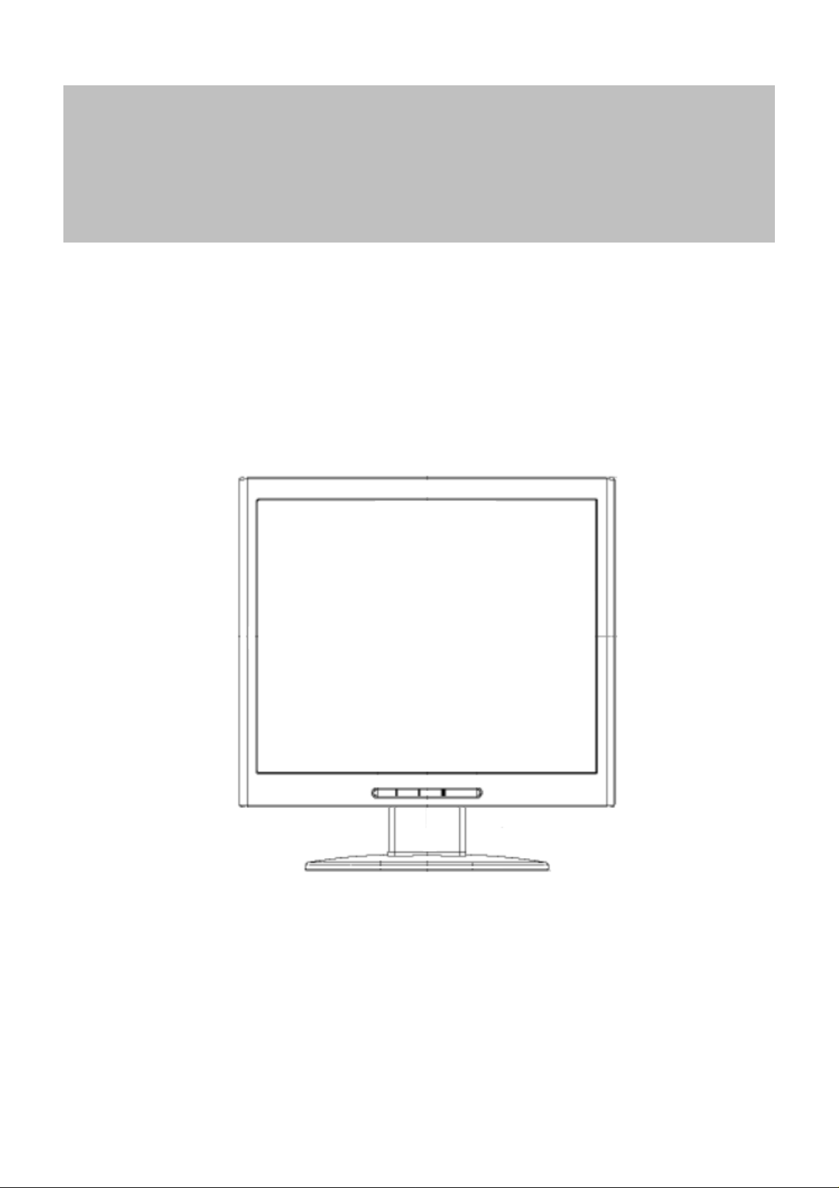
17” LCD Monitor
L1702
THESE DOCUMENTS ARE FOR REPAIR SERVICE INFORMATION ONLY. EVERY REASONABLE
EFFORT HAS BEEN MADE TO ENSURE THE ACCURACY OF THIS MANUAL; WE CANNOT GUARANTEE THE
ACCURACY OF THIS INFORMATION AFTER THE DATE OF PUBLICATION AND DISCLAIMS RELIABILITY FOR
CHANGES, ERRORS OR OMISSIONS.
1
Page 2
Table of Content
HP L1702
Revision List ----------------------------------------------------------------------------------------------------------------------------
1.Monitor Specification --------------------------------------------------------------------------------------------------------------
2.LCD Monitor Description --------------------------------- ---------------------------------------------------- -- -- ----------------
3.Operation Instructions ------------------------------------------------------------------------------------------------------------
3.1 General Instructions ---------------------------------------------------- -------------------------------------------------------- 06
3.2 Control Button ------------------------------------------------------------------------------------------------------------------- 06
3.3 Adjusting The Picture ---------------------------------------------------------------------------------------------------------- 07
4. Input/Output Specification ------------------------------------------------------------------------------------------------------
4.1 Input Signal Connector -------------------------------------------------------------------------------------------------------- 08
4.2 Factory Preset Display Modes ---------------------- ------------------------------------------------------------------------ 09
4.3 Power Supply Requirements ------------------------------------------------------------------------------------------------- 09
5.Panel Specification ------------------------------------------------------------------------ ------------------------------ -------------
5.1 General Feature ----------------------------------------------------------------------------------------------------------------- 10
5.2 Optical Characteristics --------------------------------------------------------------------------------------------------------- 11
6. Block Diagram -------------------------------------------------------- --------------------------------------------------------------
6.1 Monitor Exploded View --------------------------------------------------------------------- -- -------------------------------- 12
03
04
05
06
08
10
12
6.2 Software Flow Chart ---------------- ------------------------------ ------------------------------ -------------------------------- 13
6.3 Electrical Block Diagram ------------------------------------------------------------------------------------------------------- 15
6.3.1 Scalar Board ---------------------------------------------------------------------------------------------------------------- 15
6.3.2 Inverter/Power Board ----------------------------------------- -- -- -- -- -- -------------------------------------------------- 16
7. Schematic ----------------------------------------------------------------------------------------------------------------------------
7.1 Main Board ---------------------------------------------------------------------------------------------------------------------- 17
7.2 Power Board -------------------------------------------------------------------------------------------------------------------- 23
8. PCB Layout -------------------------------------------------------------------------------- ------------------------------------------
8.1 Main Board ---------------------------- ---------------------------------------------------------- --------------------------------- 26
8.2 Inverter/Power Board -------------------------------------------------- ------------------------------ --------------------------- 27
8.3 Key Board ----------------------------- -------------------------------------------------------------------------------------------- 27
9. Maintainability -----------------------------------------------------------------------------------------------------------------------
9.1 Equipments and Tools Requirements -------------------------------------------------------------------------------------- 28
9.2 Trouble Shooting ---------------------------------------------------------------------------------------------------------------- 29
9.2.1 Main Board --------------------------------------------------------------------------------------------------------------- 29
9.2.2 Power/Inverter Board --------------------------------------------------------------------------------------------------- 30
17
26
28
9.2.3 Key Pad Board ------------------------------------------------------------------------------------------------------------- 32
10. White-Balance, Luminance Adjustment ---------------------------------------------------------------------------------
11. EDID Content ----------------------------------------------------------------------------------------------------------------------
12. BOM List ------------------------------------------------------------------------------------- ---------------------------- ------------
2
33
35
36
Page 3

HP L1702
Revision List
Version Date Revision History TPV Model Name
A00 Feb-03-06 Initial release T782KAXHTZHPN
3
Page 4
1.Monitor Specification
Items Description
Driving system TFT Color LCD
Panel M170EN05 V.1
Size (Active Area) 337.920(H) x270.336 (V) (43.2cm 17.0")
HP L1702
LCD Panel
Input
Display Colors Over 16 million Colors
Dot Clock 140MHz
Max. Resolution 1280 x 1024
Plug & Play VESA DDC2BTM
Pixel pitch 0.264mm( H )x 0.264mm( V )
Response time (typ.) 16 ms
White Luminance 260
Contrast Ratio 450:1
Video Analog
Sync. Type H/V TTL
H-Frequency 30kHz – 81kHz
V-Frequency 56-76Hz
ON Mode
40W
≤
Power Consumption
Power Source 90~265VAC,47~63Hz
Environmental
Considerations
Main Dimensions
Humidity Operating 20% to 80%
Altitude Operating 0 to 12,000 feet
Sleep Mode
OFF Mode
Operating Temp: 5°C to 35°C
Storage Temp.: -20°C to 60°C
Operating Humidity : 20% to 80%
Mounted Overall(W*H*D) 379.0mm*450.0mm*198.0mm
Screen Opening(W*H*D) 340mm*272mm*430mm(Diagonal)
≤
≤
2W
2W
4
Page 5
HP L1702
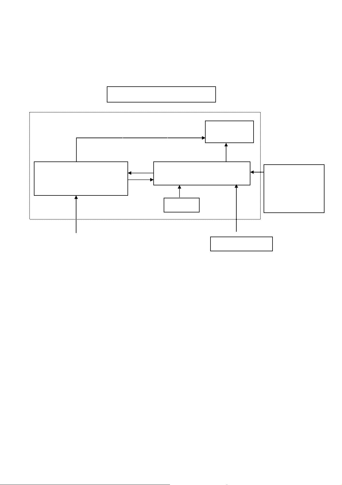
2.LCD Monitor Description
The LCD Monitor will contain a main board, a power board, and a key board which house the flat panel control
logic, brightness control logic and DDC.
The power board will provide AC to DC Inverter voltage to drive the backlight of panel and the main board chips
each voltage.
(Include adapter and inverter)
Power Board
AC-IN
90V-264V
Monitor Block Diagram
CCFT Drive.
Main Board
Keyboard
Flat Panel and
CCFL backlight
RS232 Connector
For white balance
adjustment in
factory mode
Video signal, DDC
HOST Computer
5
Page 6
HP L1702
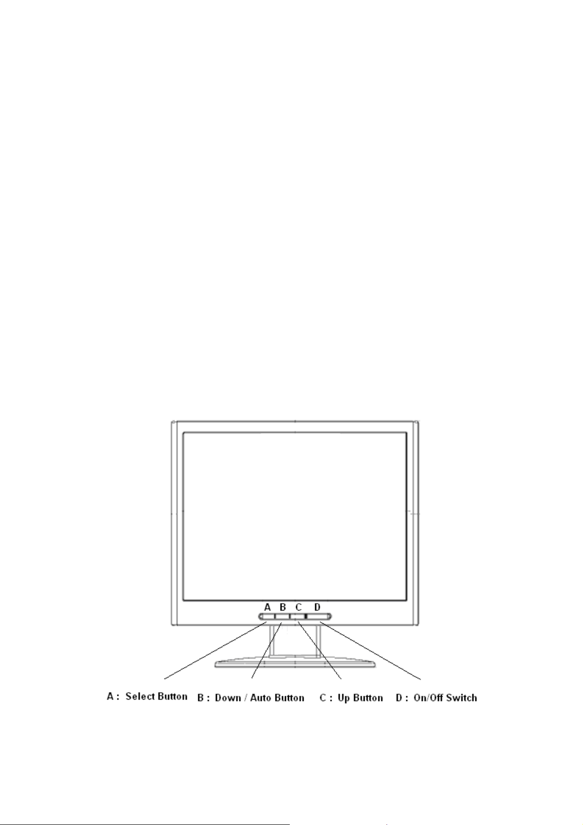
3. Operation Instructions
3.1 General Instructions
Press the power button to turn the monitor on or off. The other control buttons are located at front of the panel.
By changing these settings, the picture can be adjusted to your personal performance.
The power cord should be connected and insert to adaptor.
-
Connect the video cable from the monitor to the computer VGA card.
-
- Press the power button to turn on the monitor, the po wer indicator will light up to Green.
3.2 Control Buttons
- Power Button:
When pressed, the monitor enters the off mode, and the LED turns blank. Press again to restore normal status.
- (Down/ Auto) and + ( Up) Button:
The -/+ Button is browse OSD key. Press a select into adjustment.
The Auto Adjust Key is used to automatically set the H Position, V Position, Clock and Phase.
- Select Key:
Select key is into OSD sub-menu hot key when OSD turn on.
- Power Indicator:
Green — Power On mode.
Amber — Power Saving mode.
Blank — Power Off Mode.
6
Page 7
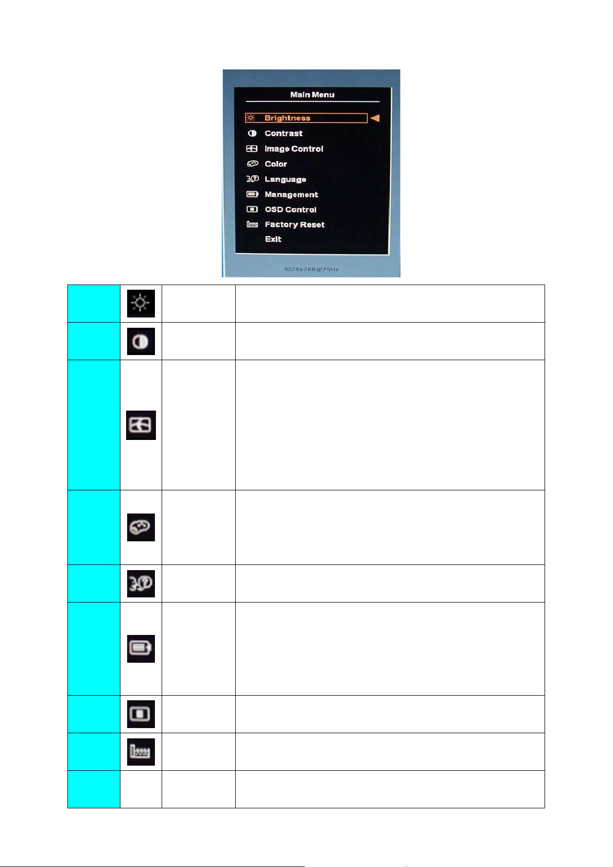
3.3 Adjust the Picture
HP L1702
1.
2.
3.
4.
5
Brightness Adjust the brightness.
Contrast Adjust the contrast
Adjust the:
Auto Adjustment: Adjusts the main settings and produces a stable,
centered image.
Image Control
Color
Language Shows the language of the OSD window.
H-Position: horizontal position of the screen image.
V-Position: vertical position of the screen image.
Clock: frequency of the pixel clock to minimize vertical bar.
Phase: phase value to minimize horizontal jitters.
9300K: recall 9300K color
6500K-sRGB: recall 6500K sRGB color
Custom Color: adjusts the color tint of white, and the red, green,
and blue (RGB) mix for colors.
6.
7.
8.
9.
Management
OSD Control
Factory Reset
Exit Closes the OSD window.
Power Saver: enable/disable power saving
Power On Recall: enable/disable power recall
Mode Display: enable/disable mode display
Sleep Timer: set sleep timer
Basic Menu: set to basic menu
OSD (on Screen Display) settings: adjusts the H/V position,
timeout, On Screen Display window.
Resets the display to original factory settings for color, brightness,
phase, and clock.
7
Page 8
HP L1702
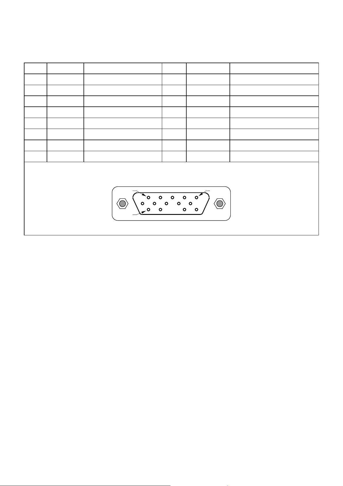
4. Input/Output Specification
4.1 Input Signal Connector
Pin Mnemonic Signal Pin Mnemonic Signal
1 RV Red Video 9 +5 V +5 V
2 GV Green Video/Sync on Green 10 SG Sync Ground
3 BV Blue Video 11 NC None
4 NC None 12 SDA DDC Data
5 GND Ground (DDC Return) 13 HS Horizontal Sync
6 RG Red GND 14 VS Vertical Sync
7 GG Green GND 15 SCL DDC Clock
8 BG Blue GND
PIN 1
PIN 11
VGA connector layout
PIN 5
8
Page 9

4.2 Factory Preset Display Modes
HP L1702
Pixel
Preset
1 640 x 480 31.469 - 59.940 - 25.175 VGA
2 640 x 480 37.861 - 72.809 - 31.500 VESA
3 640 x 480 37.500 - 75.000 - 31.500 VESA
4 720 x 400 31.469 - 70.087 + 28.322 VGA
5 800 x 600 37.879 + 60.317 + 40.000 VESA
6 800 x 600 48.077 + 72.188 + 50.000 VESA
7 800 x 600 46.875 + 75.000 + 49.500 VESA
8 832 x 624 49.726 +/- 74.551 +/- 57.284 MAC
9 1024 x 768 48.363 - 60.004 - 65.000 VESA
10 1024 x 768 56.476 - 70.069 - 75.000 VESA
11 1024 x 768 60.023 + 75.029 + 78.750 VESA
12 1152 x 870 68.68 - 75.06 - 100.000 Mac
13 1152 x 900 71.71 - 76.05 - 105.561 Sun
14 1280 x 1024 63.98 + 60.02 + 108.000 VESA
Format
Horz Freq
(KHz)
Horz
Polarity
Vert Freq
(Hz)
Vert
Polarity
Pixel Clk
(MHz) Source
15 1280 x 1024 79.97 + 75.02 + 135.000 VESA
4.3 Power Supply Requirements
Parameter Range
AC Input Voltage 90 to 265V
AC Input Frequency 47 to 63 Hz
Inrush Current 50A MAX AT 220VAC and 30A AT 120VAC
Leakage Current 5 mA MAX at 120VAC
Power consumption
≤37W
9
Page 10
HP L1702
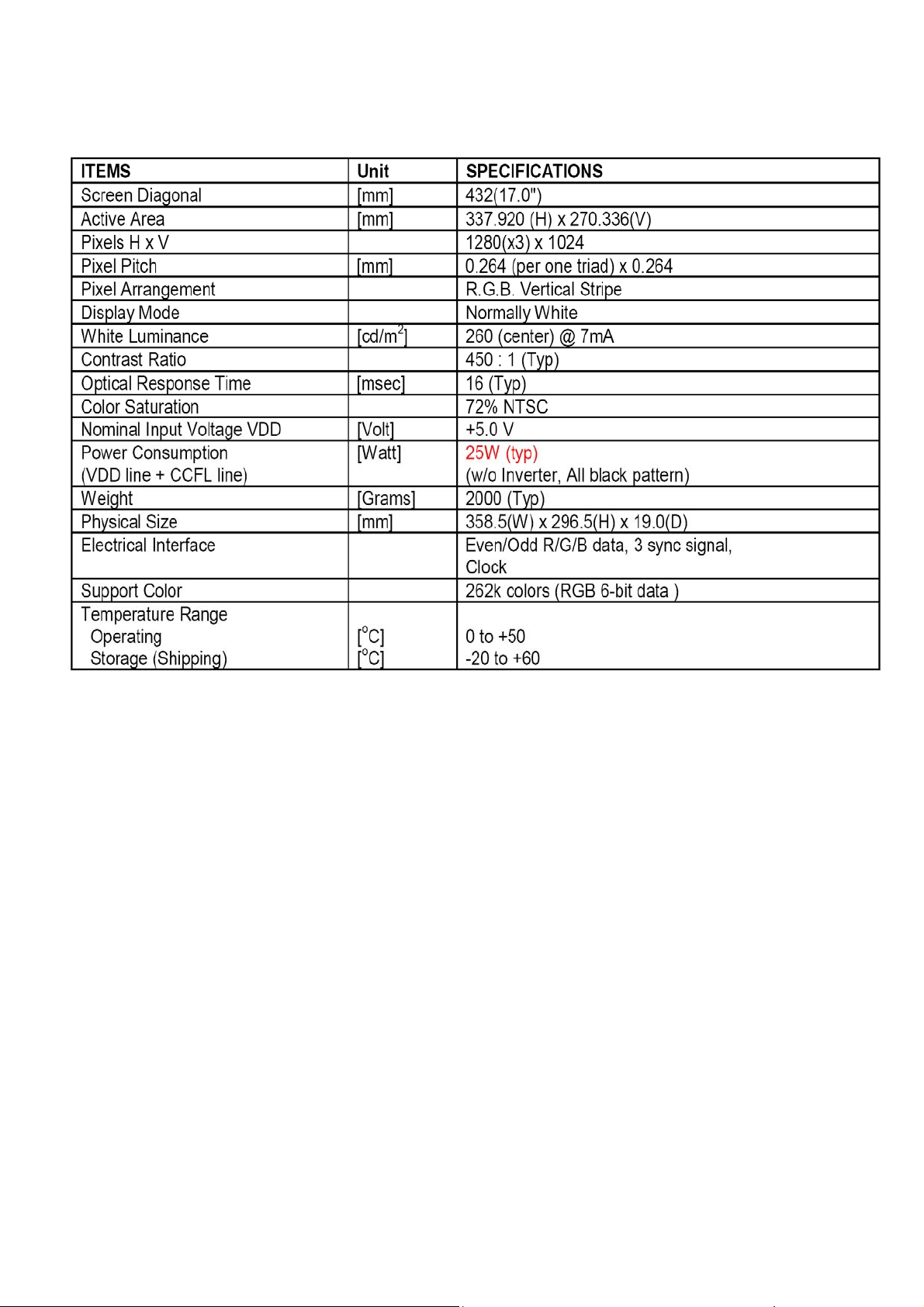
5. Panel Specification
5.1 General Feature
10
Page 11
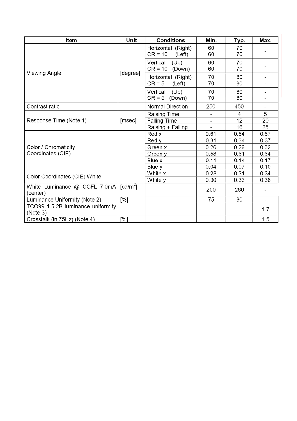
5.2 Optical Characteristics
HP L1702
11
Page 12
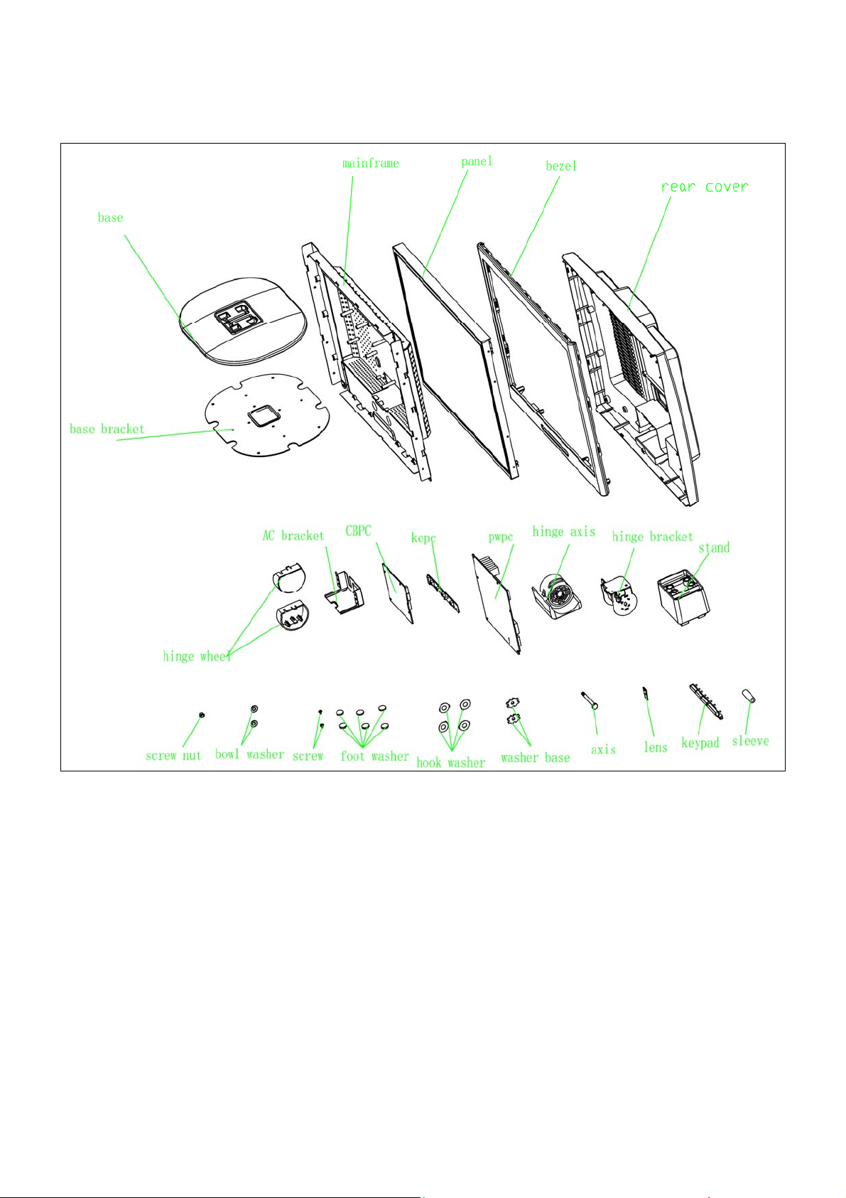
6. Block Diagram
6.1 Monitor Exploded View
HP L1702
12
Page 13
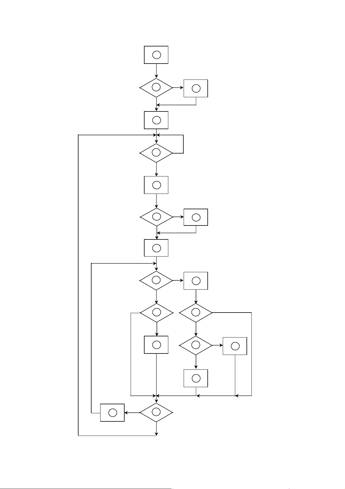
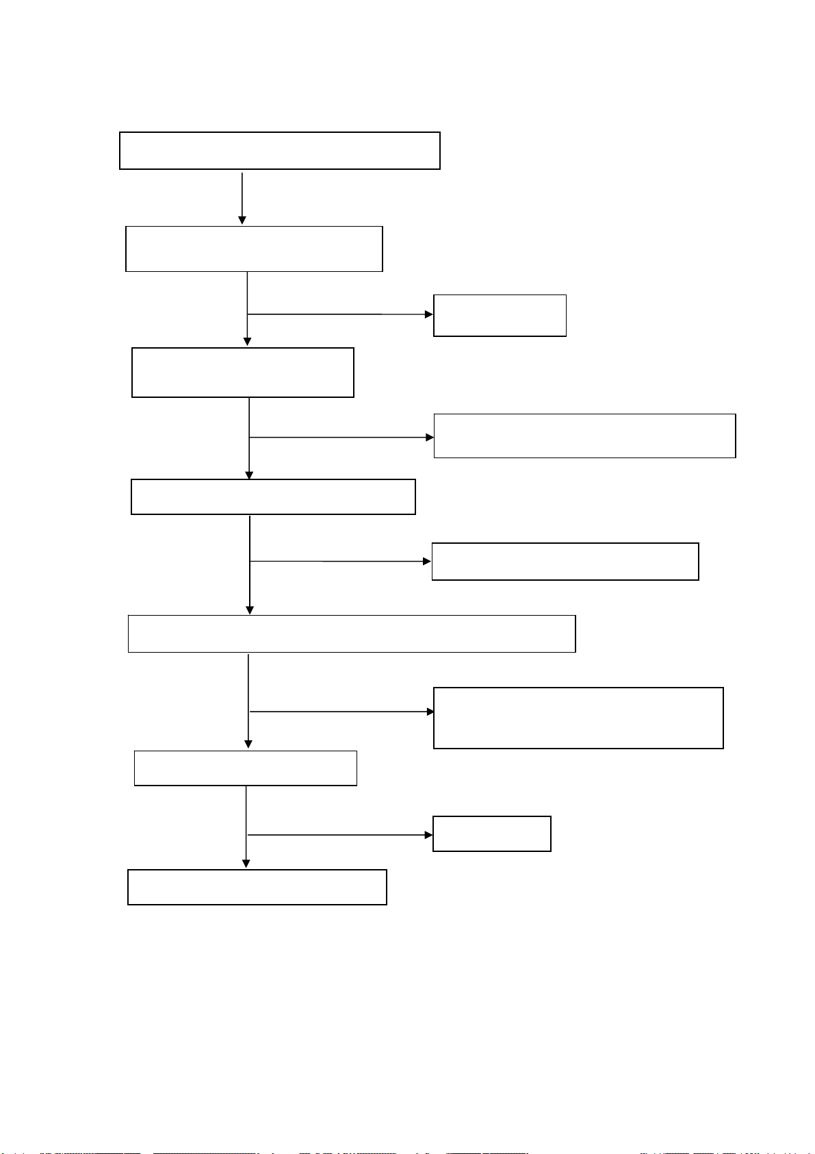
6.2 Software Flow Chart
HP L1702
1
Y
2
3
N
4
5
Y
N
6
N
7
8
Y
9
Y
N
11
10
N
12
13
N
Y
Y
14
15
N
16
Y
17
18
N
19
Y
13
Page 14
REMARK:
1) MCU initialize.
2) Is the EEprom blank?
3) Program the EEprom by default values.
4) Get the PWM value of brightness from EEprom.
5) Is the power key pressed?
6) Clear all global flags.
7) Are the AUTO and SELECT keys pressed?
8) Enter factory mode.
9) Save the power key status into EEprom.
Turn on the LED and set it to green color.
HP L1702
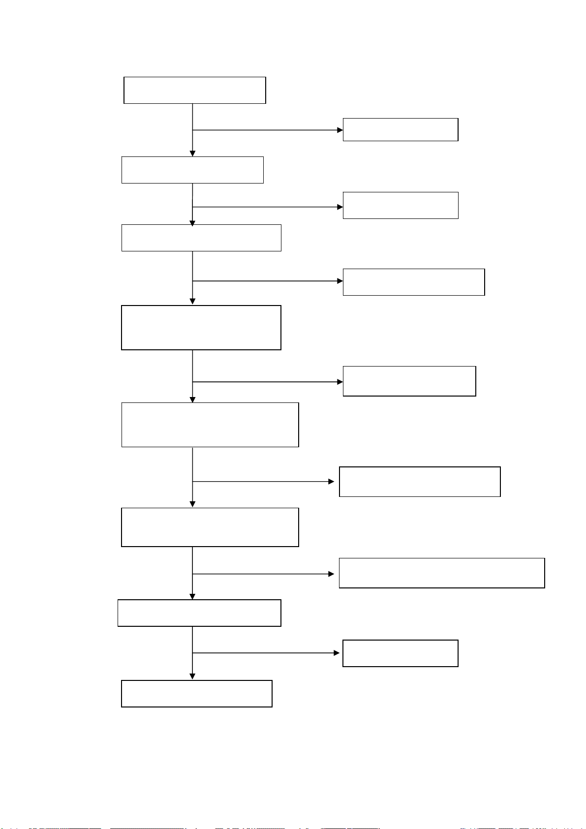
Scalar initialize.
10) In standby mode?
11) Update the lifetime of back light.
12) Check the analog port, are they’re any signals coming?
13) Does the scalar send out an interrupt request?
14) Wake up the scalar.
15) Are there any signals coming from analog port?
16) Display "No connection Check Signal Cable" message. And go into standby mode after the message
disappear.
17) Program the scalar to be able to show the coming mode.
18) Process the OSD display.
19) Read the keyboard. Is the power key pressed?
14
Page 15
6.3 Electrical Block Diagram
6.3.1 Scalar Board Block Diagram
HP L1702
EEPROM
AT24C16AN
(U602)
Crystal
20MHz
X601
MCU
(U601)
Key Board
(CN602)
Crystal
14.318MHz
(X401)
LCD Interface
Scalar MST9111B
(Include : ADC,OSD)
(U401)
H sync
V sync
RGB
D-Sub
Connector
(CN301)
DDC_CLK
DDC_DAT
EEPROM
AT24C02N
(U301)
15
Page 16

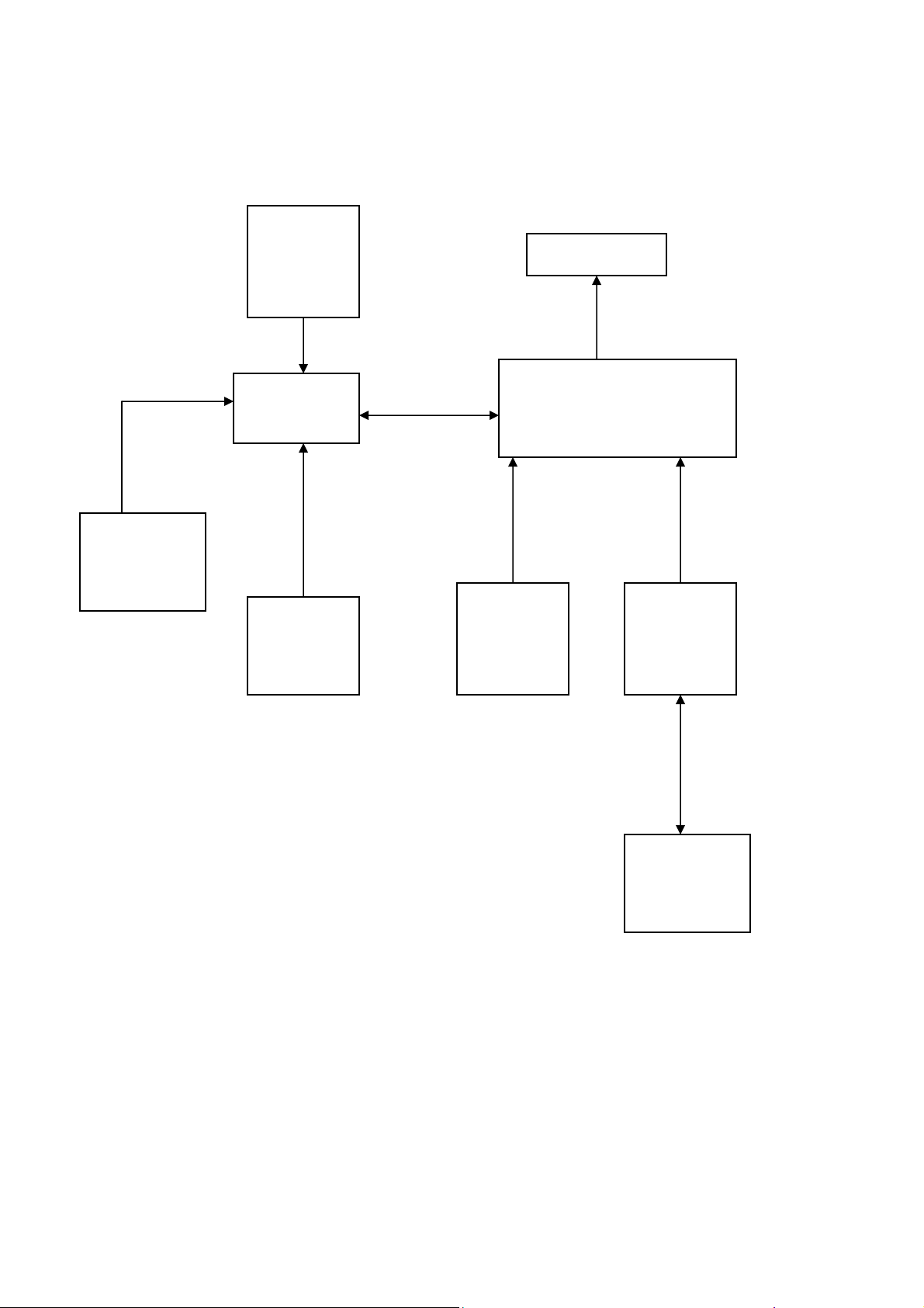
6.3.2 Inverter / Power Board Block Diagram
AC inlet filter Rectifier and filter
Start circuit
Transformer
Rectifier and filter
HP L1702
12V/5V
To main board
Switching circuit
PWM control IC&MOSFET
On/off control
Start circuit
PWM control IC
BUCK and chock
Dimming control
LC royer circuit
Feedback circuit
Ballast capacitor
Feebback circuit
12V
lamp
16
Page 17

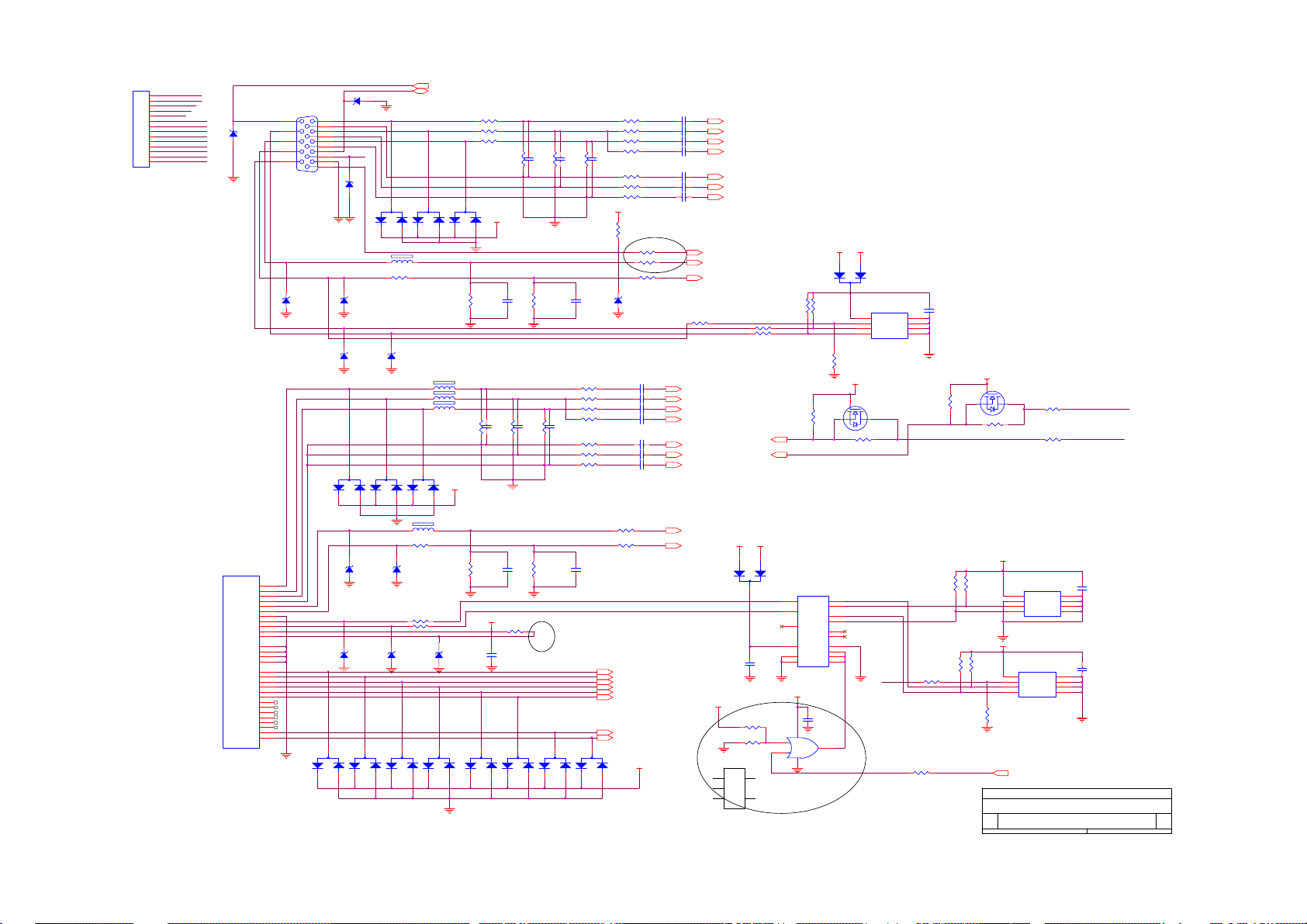
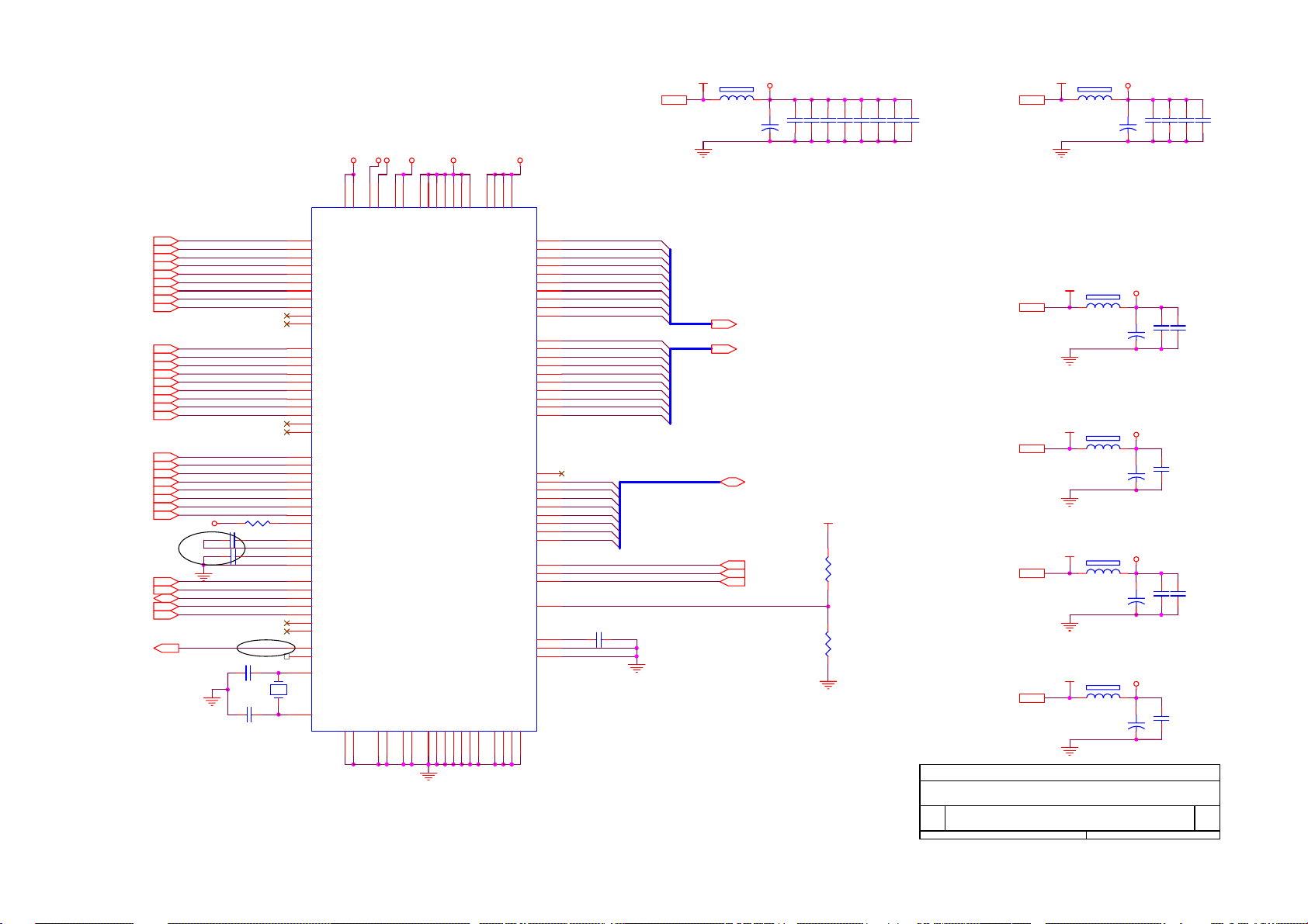
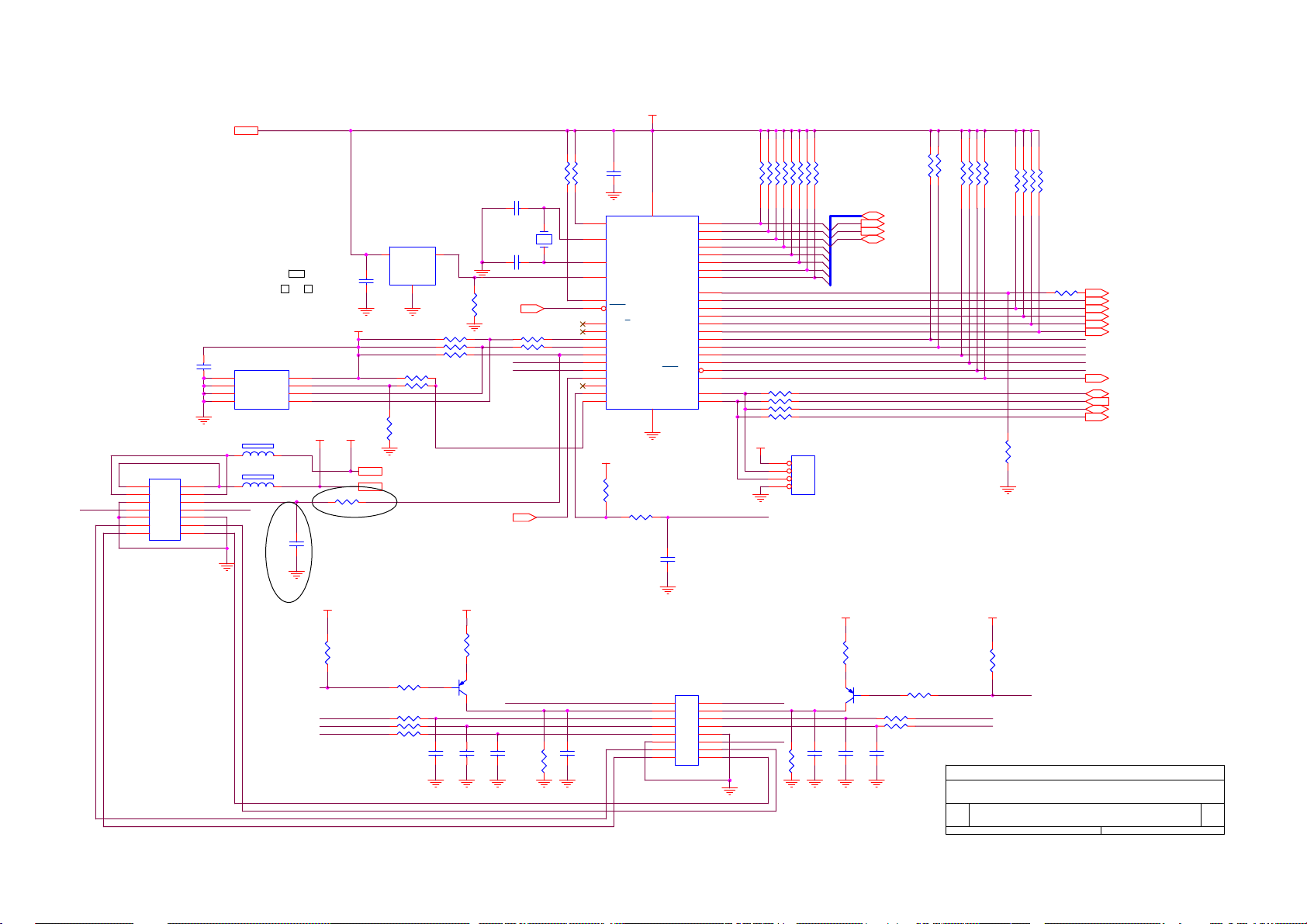
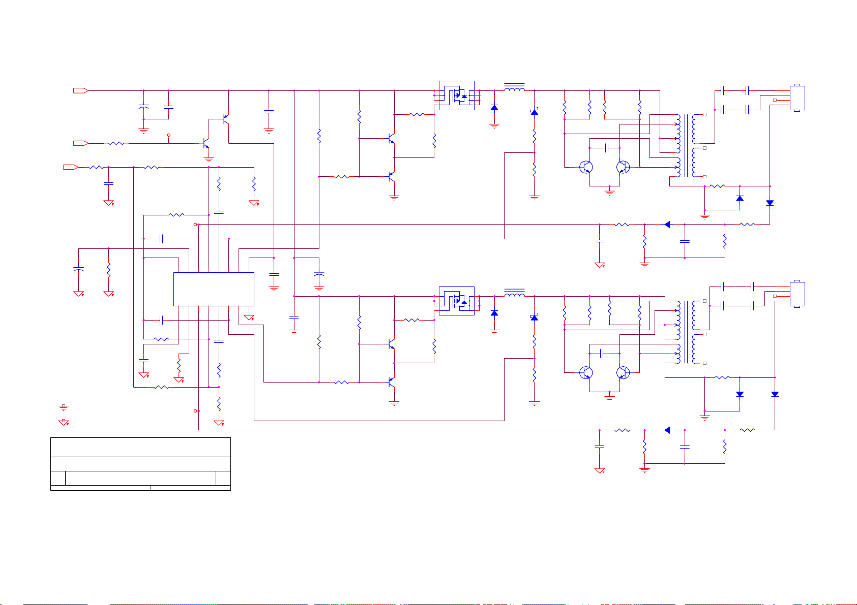
7. Schematic
7.1 Main Board
HP L1702
MST9111B SCHEMATIC
VCPU
VAA4
VCC5V
VAA3
VCC12V
VCC2.5
VAA1
VAA2
VCC12V
VCC3.3
VCC5V
VCPU
B1
TXD
RXD
DDC_DAT
ST_DET1
DVI-DDCSET
3.INPUT
B3
ST_DET1
DDC_CLK
DDC_DAT SCL
RXD
TXD
VCC5V
VCC12V
VCPU
onPANEL_5V/3.3V
onBACKLITE
6.MCU
B4
onBACKLITE
onPanel_5V/3.3V
VCPU
VCC12V
VCC3.3
VCC2.5
VAA1
VAA2
VAA3
VAA4
VCC5V
2.POWER
GNDR
GNDG
SOGDDC_CLK
GNDB
HSYNC
VSYNC
RIN1
GNDR1
GIN1
GNDG1
SOG1
BIN1
GNDB1
HSYNC1
VSYNC1
CLK+
CLK-
DVI-DDCSET
HWRESET
AD[0..7]
AdjBACKLITE
VLCD
RIN
GIN
BIN
R+
R-
G+
GB+
B-
SDA
RDZ
WRZ
CSZ
ALE
B2
INT
AD[0..7]
81X90 FOR HPQ
RIN
GNDR
GIN
GNDG
SOG
BIN
GNDB
HSYNC
VSYNC
RIN1
GNDR1
GIN1
GNDG1
SOG1
BIN1
GNDB1
HSYNC1
VSYNC1
R+
RG+
GB+
BCLK+
CLK-
CSZ
SCL
SDA
HWRESET
INT
AD[0..7]
ALE
RDZ
WRZ
VCC2.5
VCC3.3
VAA1
VAA2
VAA3
VAA4
PA[0..9]
PB[0..9]
VCC2.5 VAA1 VAA2
VCC3.3
PA[0..9]
PB[0..9]
B5
PA[0..9]
PB[0..9]
VAA4VAA3
VLCD
VLCD
5.PANEL INTERFACE
VLCD
AdjBACKLITE
4.SCALER
Title
Size Document Number Rev
B
Date: Sheet
MST9111B for AOC
TOP
16Tuesday, March 30, 2004
of
A
17
Page 18

HP L1702
Brightness
10K 1/16W
AdjBACKLITE4
VCC5V
onPanel_5V/3.3V6
VCC5V
VCC12V
CON402(PITCH 2.00)
CN201
GND
1
GND
3
VCC12V
5
GND
7
VCC5V
9
GND
11
VCC5V
R213
R205 4.7K 1/16W
1
3
D203
BAV99
1
2
R206
10K 1/16W
R207 4.7K 1/16W
C207
0.1uF
VCC5V
32
2
4
6
8
10
12
R203
1K 1/16W
Q202
PMBS3904
VCC5V
1
ON_OFF
DIM
VCC12V
GND
VCC5V
GND
R204
1K 1/16W
R208
10K 1/16W
32
Q204
PMBS3904
D204
7.5V
220uF/25V
+
VLCD
+
C202
C206
NC
Q203
AO3401
C208
10uF
+
VLCD 5
VCC5V
C203
0.1uF
0 1/16W
R211
10K 1/16W
R209
R201
D201 SR34
FB201
NC
C204
+
220uF/25V
VCC3.3
R210
NC
0 1/16W
C205
0.1uF
VCC12V 6
VCC5V+
VCC5V
VCC5V 3,6
VCPU
VCPU 6
C201
0.1uF
R202
10K 1/16W
32
Q201
PMBS3904
R212 4.7K 1/16W
1
onBACKLITE 6
VCC5V+
C214
0.1uF
VCC5V+
TO-252
U202
3
VIN
1
ADJ
AIC1084-33CE
D202
C210
0.1uF
ES3D
VOUT
SOT-223
U201
RT9164-25CG
3 2
VI VO
2
D205
3.9V
GND
1
+
C215
47uF/25V
D206
3.9V
C211
47uF/25V
C216
0.1uF
+
FB202
600 OHM
VCC3.3
VAA1
VAA2
VAA3
VAA4
VCC2.5
VCC2.5 4
C212
0.1uF
VCPU
VCPU 6
VCC3.3 4
VAA1 4
VAA2 4
VAA3 4
VAA4 4
18
Title
Size Document Number Rev
B
Date: Sheet
MST9111B for AOC
POWER
of
26Tuesday, March 30, 2004
A
Page 19
CN303
CONN
HP L1702
RXD
RXD 6
TXD
PC5V
1
HSI-1
2
VSI-1
3
CLK_DDC
4
DAT_DDC
5
TXD
6
RXD
7
VGA_CON
8
AB+
9
AB-
10
AG+
11
AG-
12
AR+
13
AR-
14
MLL5232B 5.6V
CN302
RGB GND
HSYNC
VSYNC
SYNC GND
DDC SCL
DDC SDA
1/3shield
2/4shield
0/5shield
clk shield
DVI-I
D329
DAT0+
DAT0DAT1+
DAT1DAT2+
DAT2DAT3+
DAT3DAT4+
DAT4DAT5+
DAT5-
11
12
13
14
15
HSI-1
VSI-1
D305
MLL5232B 5.6V
CLK_DDC
DAT_DDC
25
R
26
G
27
B
29
28
8
15
CLK_DDC2
6
DAT_DDC2
7
14
+5V
16
HPD
11
3
19
22
18
17
10
9
2
1
13
12
5
4
21
20
23
clk+
24
clk-
CN301
DB15
1
6
2
7
3
8
4
9
5
10
MLL5232B 5.6V
2
D327 MLL5232B 5.6V
VGA_CON
D328
2
3
D319
BAV99
1
AR+
ARAG+
AGAB+
AB-
PC5V
2
FB304 150 OHM
R314 100 1/16W
D306
MLL5232B 5.6V
D308
MLL5232B 5.6V
3
D310
BAV99
2
1
HSI-2
VSI-2
D314
MLL5232B 5.6V
D316
LL5232B 5.6V 5%
3
D320
BAV99
1
2
TXD 6
3
3
D301
BAV99
1
2
D309
MLL5232B 5.6V
FB305
FB306 30OHM
FB307 30 OHM
3
3
D312
D311
BAV99
BAV99
2
1
FB308 150 OHM
R333 100 1/16W
D315
MLL5232B 5.6V
R337 22 1/16W
R338 22 1/16W
D317
LL5232B 5.6V 5%
3
D321
BAV99
2
1
2
D302
BAV99
1
1
D318
LL5232B 5.6V 5%
3
D322
BAV99
FB301 0 1/16W
FB302 0 1/16W
FB303 0 1/16W
3
D303
BAV99
2
30 OHM
R326
75 1/16W
VCC5V
2
1
1
R316
2.2K 1/16W
C318
NC
R335
2.2K 1/16W
DVI5V
3
D323
BAV99
75 1/16W
VCC5V
C327
0.1uF
1
R301
C311
33pF
R327
75 1/16W
C324
33pF
R339
10K 1/16W
2
R302 100 1/16W
R312 100 1/16W
R313 1K 1/16W
R315 1K 1/16W
C314 0.047uF
C315 0.047uF
C316 0.047uF
C317 0.001uF
C321 0.047uF
C322 0.047uF
C323 0.047uF
VCC5V
C302 0.047uF
C303 0.047uF
C304 0.047uF
C305 0.001uF
C308 0.047uF
C309 0.047uF
C310 0.047uF
R303 100 1/16W
R304 100 1/16W
C307
R307
NC
75 1/16W
C312
220pF
R322 33 1/16W
R323 33 1/16W
R324 33 1/16W
R325 470 1/16W
R329 68 1/16W
R330 68 1/16W
R331 68 1/16W
R332 150 1/16W
R334 1K 1/16W
C325
220pF
3
D326
BAV99
1
2
R305 470 1/16W
R308 100 1/16W
R309 100 1/16W
R310 100 1/16W
VCC5V
R311
10K 1/16W
D307
MLL5232B 5.6V
B+ 4
B- 4
G+ 4
G- 4
R+ 4
R- 4
CLK+ 4
CLK- 4
C306
C301
R306
NC
NC
75 1/16W
R317
10K 1/16W
C319
C320
R328
NC
NC
75 1/16W
R336
10K 1/16W
3
3
D325
D324
BAV99
BAV99
1
2
1
ST_DET1 6
HSYNC 4
VSYNC 4
R342 22 1/16W
RIN1 4
GIN1 4
BIN1 4
SOG1 4
GNDR1 4
GNDG1 4
GNDB1 4
HSYNC1 4
VSYNC1 4
DVI5V
R361 4.7K 1/16W
1 5
2
3
RIN 4
GIN 4
BIN 4
SOG 4
GNDR 4
GNDG 4
GNDB 4
VCC5V
1
R360
SOT23
4.7K 1/16W
R320 47 1/16W
R321 47 1/16W
DDC_DAT6
DDC_CLK6
DVI5V
2
D313
BAV70
3
SCL_D
SDA_D
DDC-VCC_DVI
C328
0.1uF
DDC-VCC_DVI
0 1/16W
1
2
4
VCC5V
PC5V
1
2
D304
BAV70
R319
4.7K 1/16W
SCL/I
SDA/I
0A
1A
0B
1B
0C
1C
INH
SA
SB
SC
C330
0.1uF
U305A
NC7S32
4
3
U301
8
VCC
7
WP
6
SCL
AT24C02N-10SC
R351
0 1/16W
VCC5V
G
Q303
D
S
NC
0 1/16W
R355
12
13
2
1
5
3
6
11
10
9
VSI-2
1
A0
2
A1
3
A2
45
GNDSDA
R350 4.7K 1/16W
C313
0.1uF
R345
10K 1/16W
10K 1/16W
NC
R344
VCC5V
G
Q302
R358
D
S
NC
0 1/16W
8
7
6
DVI-DDCSET 6
DDC-VCC_DVI
U304
8
7
6
AT24C02N-10SC
U302
VCC
WP
SCL
AT24C02N-10SC
R359
0 1/16W
1
A0
VCC
2
A1
WP
3
A2
SCL
45
GNDSDA
DDC_D
DDC-VCC_DVI
1
A0
2
A1
3
A2
45
GNDSDA
DDC_A
MST9111B for AOC
INPUT
R357
0 1/16W
DDC-VCC_DVI
R346
10K 1/16W
DDC-VCC_DVI
R348
10K 1/16W
R352
0 1/16W
Title
Size Document Number Rev
C
Date: Sheet
R347
R356
NC
DVI-DDCSET
SCL/I
SDA/I
C326
0.1uF
C329
0.1uF
A
of
36Tuesday, March 30, 2004
R318
R354
NC
U303
14
ZA
15
ZB
4
ZC
16
VCC
7
VEE
8
GND
74VHC4053
53
19
Page 20
HP L1702
FB401
600 OHM
C402
10uF
PA[0..9] 5
PB[0..9] 5
VPO
+
AD[0..7] 6
ALE 6
RDZ 6
WRZ 6
C403
0.1uF
C404
0.1uF
C405
0.1uF
VCC3.3
C406
C407
0.1uF
0.1uF
R402
4.7K 1/16W
R403
NC
C408
0.1uF
C409
0.1uF
C410
0.1uF
VCC2.52
VAA12
VAA22
VAA32
VAA42
VCC3.3
VCC3.32
VDPLL
VAD
VPLL
183516814
AVDD
AVSS
19
343917
AVDD
AVSS
124
AVDD_PLL
AVDD_PLL
MST9111B
AVSS_PLL
AVSS_PLL
12551156627383
U401
X401
126
127
118
117
128
116
115
121
119
120
122
123
33
32
30
29
31
28
27
25
26
23
24
22
20
21
1
3
4
6
7
9
10
12
13
15
37
38
36
40
42
41
43
44
45
RIN0
RIN0M
GIN0
GIN0M
SOGIN0
BIN0
BIN0M
HSYNC0
VSYNC0
DDC1_CLK
DDC1_DAT
RIN1
RIN1M
GIN1
GIN1M
SOGIN1
BIN1
BIN1M
HSYNC1
VSYNC1
DDC2_CLK
DDC2_DAT
R+
RG+
GB+
BCK+
CKREXT
REFP
REFM
RMID
REF_GND
CSZ
SCL
SDA
INT
HWRESETZ
DDCROM_CLK
DDCROM_DAT
PWM0
PWM1
XIN
XOUT
RIN3
GNDR3
GIN3
GNDG3
SOG3
BIN3
GNDB3
HSYNC3
VSYNC3
RIN13
GNDR13
GIN13
GNDG13
SOG13
BIN13
GNDB13
HSYNC13
VSYNC13
R+3
R-3
G+3
G-3
B+3
B-3
CLK+3
CLK-3
CSZ6
SCL6
SDA6
INT6
HWRESET6
AdjBACKLITE2
VDVI
C401 0.1uF
C421 0.1uF
R401 390 1/16W
C426 22pF
14.318MHz
C427 22pF
AVDD_DVI
VDVI
5561728294
VDDP
AVDD_DVI
AVSS_DVI
AVSS_DVI
VDDP
GNDP
VDDP
GNDP
VPO
VDDP
GNDP
107
VDDP
GNDP
VDDP
GNDP
114586485111
VDDP
VDDC
VDDC
VDDC
LVA3P
LVA3M
LVACKP
LVACKM
LVA2P
LVA2M
LVA1P
LVA1M
LVA0P
LVA0M
LVB3P
LVB3M
LVBCKP
LVBCKM
LVB2P
LVB2M
LVB1P
LVB1M
LVB0P
LVB0M
BUSTYPE
TESTPIN
GNDP
GNDP
GNDC
GNDC
106
1135763
8495112
VDD
VDDC
RDZ
WRZ
VPLL
GPLL
GNDC
AD0
AD1
AD2
AD3
AD4
AD5
AD6
AD7
ALE
NC
GNDC
70
71
74
75
76
77
78
79
80
81
86
87
88
89
90
91
92
93
96
97
46
47
48
49
50
51
52
53
54
59
60
65
69
103
102
2
PA0
PA1
PA2
PA3
PA4
PA5
PA6
PA7
PA8
PA9
PB0
PB1
PB2
PB3
PB4
PB5
PB6
PB7
PB8
PB9
AD0
AD1
AD2
AD3
AD4
AD5
AD6
AD7
PA[0..9]
PB[0..9]
AD[0..7]
C425 0.1uF
VCC2.5
VAA1
VAA2
VAA3
VAA4
FB402
600 OHM
C411
10uF
FB403
600 OHM
10uF
FB404
600 OHM
10uF
FB405
600 OHM
10uF
FB406
600 OHM
10uF
C416
C419
C422
C428
VDD
+
VAD
+
VPLL
+
VDVI
+
VDPLL
+
C412
0.1uF
C417
0.1uF
C420
0.1uF
C423
0.1uF
C429
0.1uF
C413
0.1uF
C418
0.1uF
C424
0.1uF
C414
0.1uF
C415
0.1uF
20
Title
Size Document Number Rev
B
Date: Sheet
MST9111B for AOC
SCALER
of
46Tuesday, March 30, 2004
A
Page 21

HP L1702
PA[0..9]4
PB[0..9]4
PA[0..9]
PA0
PA1
PA2
PA3
PA4
PA5
PA6
PA7
PA8
PA9
PB0
PB1
PB2
PB3
PB4
PB5
PB6
PB7
PB8
PB9
LVA3P
LVA3M
LVACKP
LVACKM
LVA2P
LVA2M
LVA1P
LVA1M
LVA0P
LVA0M
LVB3P
LVB3M
LVBCKP
LVBCKM
LVB2P
LVB2M
LVB1P
LVB1M
LVB0P
LVB0M
LVB0M
LVB1M
LVB2M
LVBCKM
LVB3M
LVA0M
LVA1M
LVA2M
LVACKMPB[0..9]
LVA3M
C509
+
47uF/25V
RXO0RXO1RXO2RXOCRXO3RXE0RXE1RXE2RXECRXE3-
CN503
1 2
3 4
5 6
7 8
9 10
11 12
13 14
15 16
17 18
19 20
21 22
23 24
CON24A
VLCD
C510
0.1uF
RXO0+
RXO1+
RXO2+
RXOC+
RXO3+
RXE0+
RXE1+
RXE2+
RXEC+
RXE3+
VLCD 2
C511
0.1uF
LVB0P
LVB1P
LVB2P
LVBCKP
LVB3P
LVA0P
LVA1P
LVA2P
LVACKP
LVA3P
R502
0 1/16W
21
Title
MST9111B for AOC
Size Document Number Rev
A
Date: Sheet
PANEL INTERFACE
56Tuesday, March 30, 2004
of
A
Page 22
VR-OUT-L
SPKR_L+
LINE-IN-L
CN601
1 2
3 4
5 6
7 8
9 10
11 12
13 14
CON14 2mm
VCPU2
C605
0.1uF
U602
1
A0
2
A1
3
A2
4 5
GND SDA
24C16
FB601 600 OHM
FB602 600 OHM
VR-OUT-R
SPKR_R+
LINE-IN-R
VCC
SCL
1
WP
C613
0.1uF
3
2
8
7
6
VCC5V
R627 10K 1/16W
ADD R627,R614,C613
VCC12V
3 2
C217
0.1uF
VCPU
U203
MAX810STR
VI RESET
GND
1
100K 1/16W
R605 10K 1/16W
R604 10K 1/16W
R614 10K 1/16W
R644 10K 1/16W
R638 0 1/16W
VCC12V 2
VCC5V 2,3
R637
NC
R639
C602 22pF
C604 22pF
R609 100 1/16W
R608 100 1/16W
ST_DET13
10K 1/16W
20MHz
INT4
X601
LED_O
LED_G
Standby
R601
R602
10K 1/16W
35
21
20
10
12
14
33
32
17
2
3
4
5
6
7
8
9
VCPU
C601
0.1uF
U601
NC
XTAL1
XTAL2
RESET
NC
INT0/P3.2
ALE/P
VSYNC
T1/P3.5
P5.0
P5.1
P5.2
P5.3
P5.4
P5.5
P5.6
P5.7
MYSON512
R631
10K 1/16W
R630 BEAD 600
VCPU
22 44
I/O
T0/P3.4
P7.6/CLKO
INT1/P3.3
P3.1/TXD
P3.0/RXD
VSS VCC
P1.0
P1.1
P1.2
P1.3
P1.4
P1.5
P1.6
P1.7
P6.0
P6.1
P6.2
P6.3
P6.4
P6.5
P6.6
P6.7
P7.7
DVI-DSUB SELECT
C614
0.1uF
10K 1/16W
43
42
41
40
39
38
37
36
24
25
26
27
28
29
30
31
16
18
15
19
13
11
RN601
AD0
AD1
AD2
AD3
AD4
AD5
AD6
AD7
R610 220 1/16W
R611 220 1/16W
R634 NC
R635 NC
VCPU
HP L1702
123
4
5
123
4
RN602
10K 1/16W
876
876
5
AD0
AD1
AD2
CN603
1
2
3
4
AD[0..7] 4
CSZ 4
SCL 4
SDA 4
R606
10K 1/16W
R607
10K 1/16W
123
4
876
5
4
RN604
10K 1/16W
5
R613
10K 1/16W
123
RN603
10K 1/16W
876
R636 100 1/16W
POWER
MENU
RIGHT
LEFT
MODE/SEL
DVI-DDCSET
HWRESET 4
onPANEL_5V/3.3V 2
onBACKLITE 2
ALE 4
RDZ 4
WRZ 4
DVI-DDCSET 3
DDC_DAT 3
DDC_CLK 3
TXD 3
RXD 3
VCPU
MODE/SEL
RIGHT
POWER
R642
10K 1/16W
LED_G
R616 4.7K 1/16W
R620 BEAD 600
R622 BEAD 600
R624 BEAD 600
1
C606
0.1uF
VCPU
3 2
R617
470 1/16W
Q601
PMBS3906
C608
0.1uF
C610
0.1uF
R628
NC
DVI-DSUB SELECT
LED_GRN
SPKR_L+
C615
LINE-IN-L
NC
11 12
13 14
15 16
22
CN602
1 2
3 4
5 6
7 8
9 10
CON16A
VR-OUT-L
LED_ORANGE
VR-OUT-R
SPKR_R+
LINE-IN-R
R629
NC
C616
NC
VCPU
3 2
R618
470 1/16W
Q602
1
PMBS3906
R621 BEAD 600
R623 BEAD 600
C607
0.1uF
R619 4.7K 1/16W
C609
0.1uF
Title
Size Document Number Rev
Date: Sheet
VCPU
R643
10K 1/16W
LED_O
MENU
LEFT
MST9111B for AOC
B
MPU
66Tuesday, March 30, 2004
A
of
Page 23

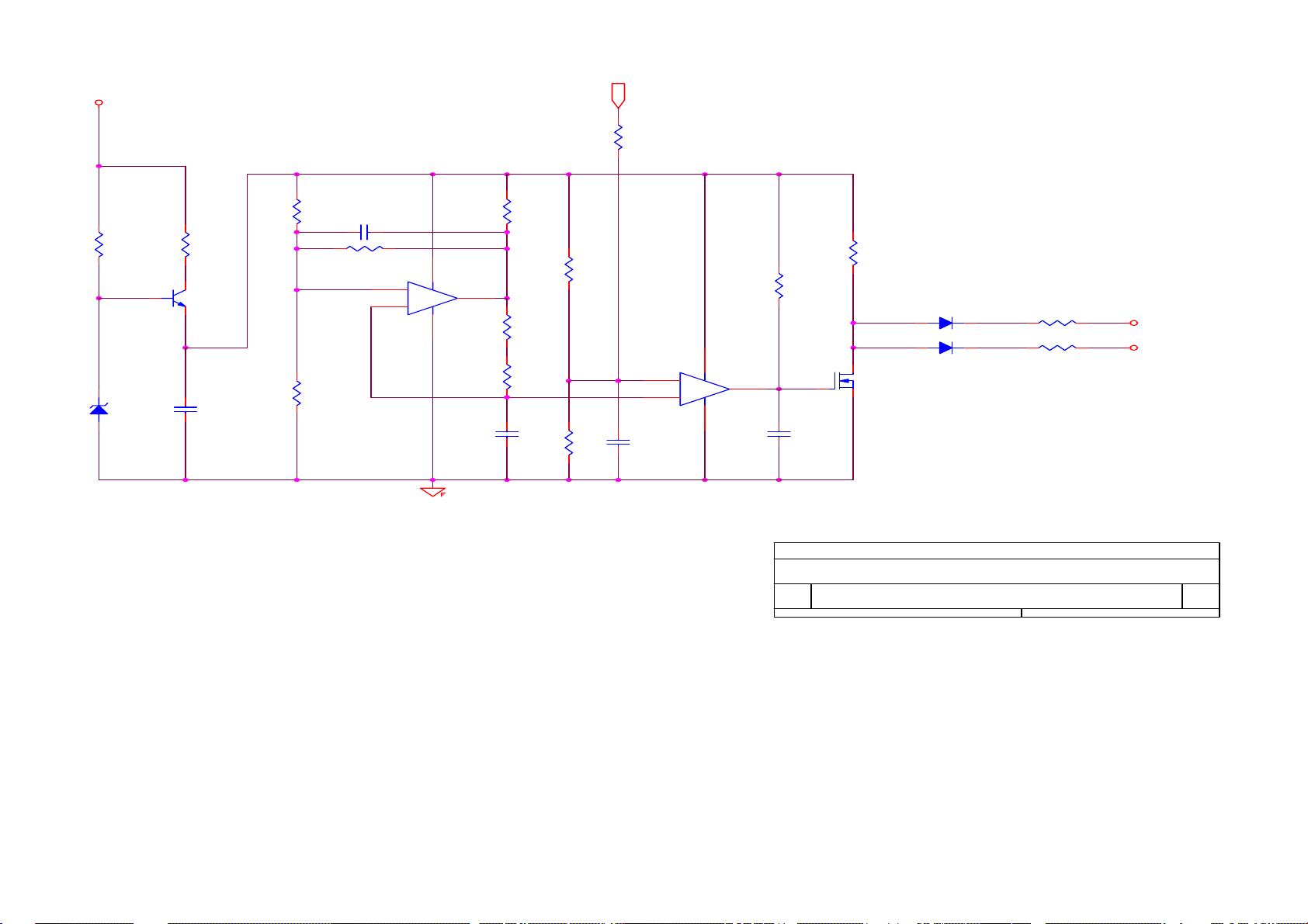
7.2 Power Board (Include Inverter And Power)
HP L1702
1
R901
1M/1206
2 3
1 4
2 3
1 4
C903 0.1uF/275V
1M/1206
R900
4
DB901
2KBP06M
3
-+
2
L901
73L174-25-LS
L902
73L174-29-LS
3
CN901
12
R902
1M/1206
C901
102PF/250V
C902
102PF/250V
NR901
61L58-050-WT
F901
2A/250V
C904
+
100uF/400V
ZD901
MTEJ20B
R912
100 1/8W
R914
24K 1/10W
R909
4.7K 1/10W
C907
0.1uF
SG6841
R906
1M 1/8W
R907
1M 1/8W
+
C906
10uF/50v
IC901
R913
10K 1/10W
72
4
8
SG6841
56
13
Q901
2PA733P
C909
0.1uF
C910
0.001uF
C908
0.1uF
R911
4.7K 1/10W
R904
NC
R905
NC
D902
IN4148
R915
10 1/10W
R930
220 1/10W
C930
470pf
C905
1500P/2KV
D902
PS102R
+
C906
22uF
R916
10K 1/10W
R910
4.7K 1/10W
Q902
2PC945P
R920
47 1/2W
D910
9
7
8
10
12
IC902
PC123FY82 4P
SP10150 10A/150V
1
3
R921
47 1/2W
1
3
10A/100V
C929
0.1uF
T901
1
UF4007
R908
0 1/10W
FB901
BEAD
O
3
5
O
6
C912
0.0033uF/250V
43
IC903
HTL431
O
R903
100K 2W
D901
23
Q903
2SK2996
1
R917
0.39 2W
D903
1N4148
2
C921
0.001uF/500V
D911
2
R929
100 1/8W
ZD902
HZ12B2
R928
1K 1/10W
R927
0 1/10W
C920
0.001uF/500V
C922
+
1000uF/16V
+
C923
1000uF/16V
R925
1K 1/10W
R926
1K 1/10W
ZD903
HZ5C1
L903
L904
+
+
R922
33K 1/10W
R924
2.4K 1/10W
C924
470uF/16V
C925
470uF/16V
+5V
R923
3.6K 1/10W
DIM
+12V
ZD904
SML4736
C926
0.1uF
C927
0.1uF
CON102
CONN 33L8009-12L-H
2
4
6
8
10
12
1
3
5
7
9
11
+12V
+5V
ON/OFF
23
AOC (Top Victory) Electronics Co., Ltd.
Title
Size Document Number Rev
B
Date: Sheet of
1.POWER OUTPUT 12V & 5 V
PWPC1742AUH1
Friday, September 23, 2005
21
A
Page 24
HP L1702
+12V
ON/OFF
DIM
+
is power GND
is signal GND
R201
NC
C207
4.7uF
C201
150uF/25V
R242
6.8K 1/10W
C203
NC
R207
NC
R202
NC
+
PROTECT
R205
47K 1/10W
C205
1uF
C206
1uF
R206
47K 1/10W
C208
330pF
R203
NC
C202
NC
1
BU_L
14
15
16
SCP
REF
2IN+
CTRT1IN+
1234567
R204
10K 1/10W
BU_R
1
32
Q201
DTC144WKA
12
13
2IN-
1IN-
Q202
3 2
R208
0 1/10W
C209
0.1uF/25V
11
2FBK
2DTC
1FBK
1DTC
C210
0.1uF/25V
R209
0 1/10W
R211
33K 1/10W
DTA144WKA
10
2OUT
1OUT
GND Vcc
8 9
C225
NC
R210
33K 1/10W
U201
TL1451ACNSR
C204
0.1uF/25V
L201
Q203 SI4431 OR AO4411
1
2
3
R212
R213
4
R216
22 1/10W
Q204 SI4431 OR AO4411
1
2
3
4
R217
22 1/10W
R214
2.2K 1/10W
R243
NC
R218
22 1/10W
C223
+
150uF/25V
C224
NC
R244
NC
R219
22 1/10W
R215
2.2K 1/10W
3.9K 1/10W
32
Q205
1
PMBS3904
Q207
1
PMBS3906
3 2
3.9K 1/10W
32
Q206
1
PMBS3904
Q208
1
PMBS3906
3 2
120UH
8
7
6
5
D201
SR24
L202
120UH
8
7
6
D202
5
SR24
1.5K 1/8W
ZD203
RLZ11B
R220
15K 1/10W
2SD5706(DIP&SMD)
R222
12K 1/10W
1.5K 1/8W
ZD204
RLZ11B
R221
15K 1/10W
R223
12K 1/10W
2SD5706(DIP&SMD)
R228
R224
Q209
1
1
Q211
R225
1.5K 1/8W
23
0.22uF/250V
R229
1.5K 1/8W
C214
0.22uF/250V
23
R226
1.5K 1/8W
C213
R240
51K 1/10W
C221
682/25V
R230
1.5K 1/8W
R241
51K 1/10W
23
Q210
2SD5706(DIP&SMD)
23
Q212
2SD5706(DIP&SMD)
R227
1.5K 1/8W
1
R231
1.5K 1/8W
1
D207
1N4148
R238
12K 1/10W
D208
1N4148
C228
C215
39pF/3KV
39pF/3KV
C216
C229
39pF/3KV
R232
C217
39pF/3KV
C218
39pF/3KV
D209
1N4148
R234
910 1/10W
R236
430 1/10W
D210
1N4148
R235
910 1/10W
C226
39pF/3KV
C227
39pF/3KV
PT201
EEL-19
PT202
EEL-19
C219
NC
8
9
10
11
1K 1/10W
8
9
10
11
R233
1K 1/10W
39pF/3KV
1
2
3
4
5
6
7
1
2
3
4
5
6
7
D205
1N4148
D206
1N4148
J2
1
2
3
4
CONN
J1
1
2
3
4
CONN
AOC (Top Victory) Electronics Co., Ltd.
Title
PWPC1742AUH1
Size Document Number Rev
B
Date: Sheet
Friday, September 23, 2005
22
of
C222
682/25V
2
R239
12K 1/10W
C220
NC
R237
430 1/10W
24
Page 25
+12V
R401
1K 1/10W
1
ZD401
RLZ5.6B
R402
470 1/8W
32
Q401
PMBS3904
C401
1uF
HP L1702
DIM
R407
300K 1/16W
R404
56K 1/16W
C405
102/NPO
R405
27K 1/16W
R406
27K 1/16W
84
3
+
2
-
IC401A
LM393
1
C403
682
R417
10K 1/16W
R408
360K 1/16W
R409
100K 1/16W
R411
150K 0805
R410
130K
C404
104
R414
22K 1/16W
R418
10K 1/16W
D401
SMD IN4148
84
5
+
6
-
IC401B
LM393
7
C406
332/NPO
Q402
RK7002
D402
SMD IN4148
R415
33K 1/16W
R416
33K 1/16W
BU_L
BU_R
25
Title
Size Document Number Rev
A
Date: Sheet
PWPC715L1236-A
of
11Friday, September 23, 2005
Page 26
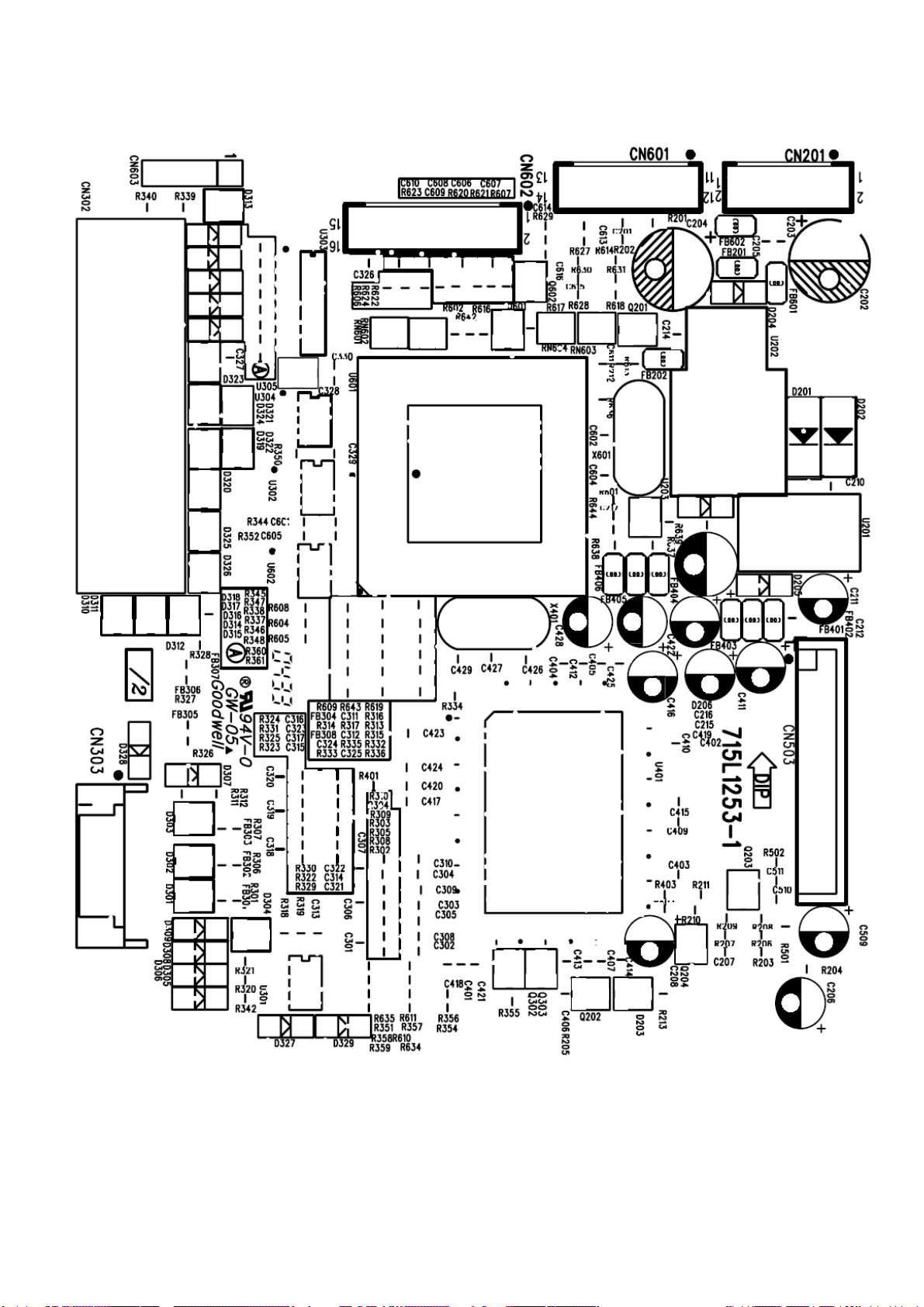
HP L1702
8. PCB Layout
8.1 Main Board
26
Page 27

8.2 Inverter / Power Board
HP L1702
8.3 Key Board
27
Page 28

9. Maintainability
9.1Equipments and Tools Requirement
1. Multi-meter.
2. Oscilloscope.
3. Pattern Generator.
4. DDC Tool with an IBM Compatible Computer.
5. Alignment Tool.
6. LCD Color Analyzer.
7. Service Manual.
8. User Manual.
HP L1702
28
Page 29
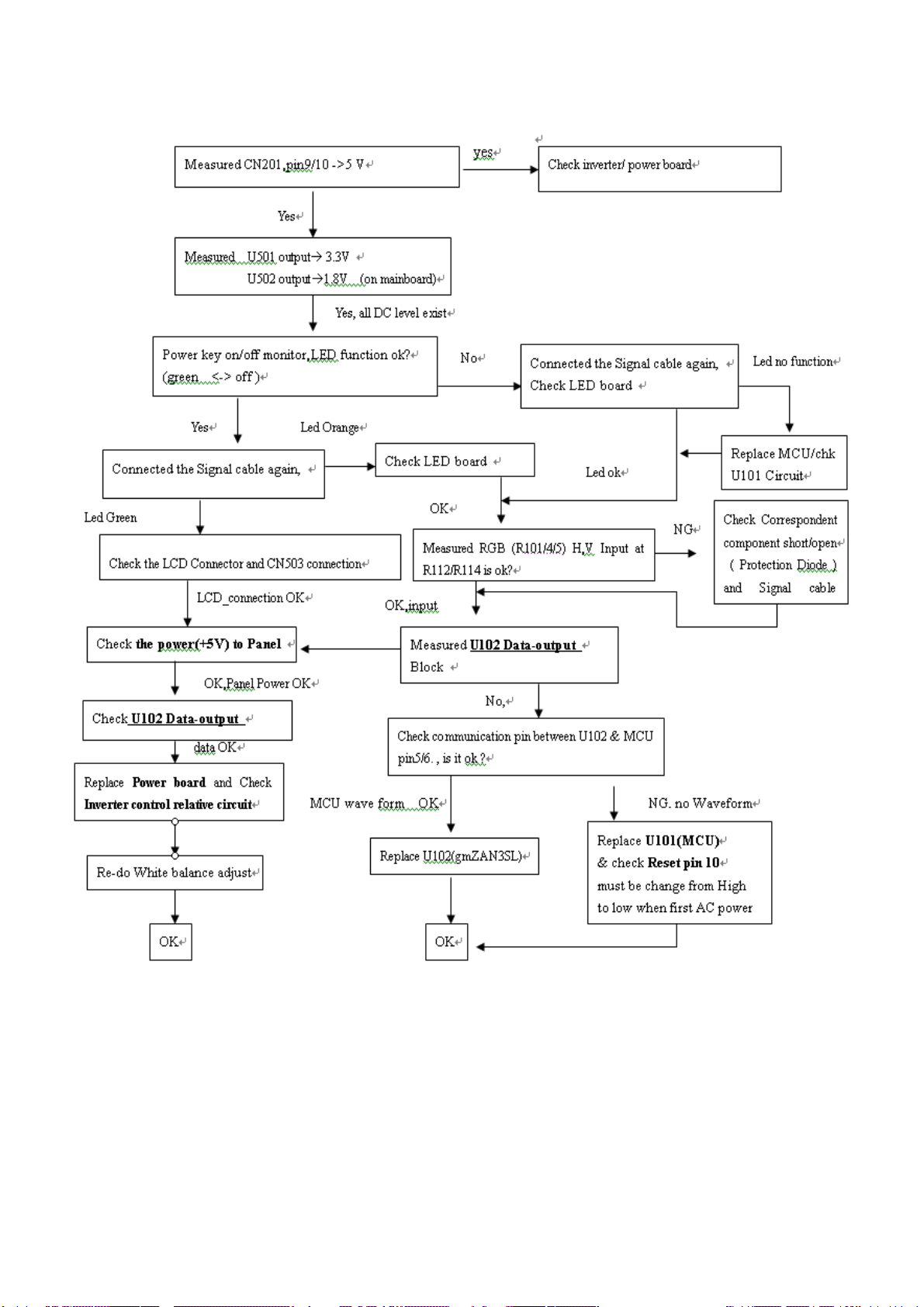
9.2 Trouble Shooting
9.2.1 Main Board
HP L1702
29
Page 30
9.2.2 Power Board
No Power
HP L1702
Check CON102 Pin12 =12V, Pin3,4=5V
OK
NG
Check AC line volt 110V or 220V
NG
OK
Check AC line
Check the voltage of C904(+)
OK
NG
Check bridge rectified circuit and F901circuit
Check start voltage for the pin3 of IC901
OK
NG
Check R906, R907 and change IC901
Check the auxiliary voltage is bigger than 10V and smaller than 20V
OK
NG
1) Check IC901
2) Check ZD901,Q901,Q902…OVP circuit
CheckIC901 Pin8 PWM wave
OK
Check Q903,R917,D910,D911,ZD904
NG
Check IC901
30
Page 31
No Backlight
Check C201(+) =12V
OK
HP L1702
NG
Check adapter circuit
Check ON/OFF signal
OK
NG
Check main board
Check U201 Pin9=12V
OK
Check the Pin1 of U201 have
sawtooth wave
OK
NG
Check Q201 or Q202 circuit
NG
Change U201/R204/C208
Check D201/D202(-) have the output
of square wave at short time
OK
NG
Check Q203/Q204/D201/D202
Check the resonant wave of Pin
2&Pin5 for PT210/PT202
OK
NG
Check Q209/Q210/Q211/Q212/C213/C214
Check the output of PT201/PT202
OK
NG
Change PT201/PT202
Check connecter & lamp
31
Page 32

9.2.3 Keypad Board
HP L1702
OSD is unstable or not working
Is Keypad board connecting normally
NG
Connect Keypad Board
OK
Is Button Switch normally
NG
Replace Button Switch
OK
Is Keypad board normally
NG
Replace Keypad Board
OK
Check main board
32
Page 33

10. White- Balance, Luminance Adjustment
Approximately 30 minutes should be allowed for warm up before proceeding
White-Balance adjustment.
1. How to do the Chroma-7120 MEM .Channel setting
A. Reference to chroma 7120 user guide
B. Use “ SC” key and “ NEXT” key to modify xyY value and use “ID” key to modify the
TEXT description Following is the procedure to do white-balance adjust
2. Setting the color temp. You want
A. 9300 color:
9300 color temp. parameter is x = 283 ±20, y = 297 ±20, Y > 180 cd/m
B. sRGB color:
sRGB color temp. parameter is x = 313±20, y = 329 ±20, Y>200 cd/m
C. 6500K color:
sRGB color temp. parameter is x = 313±20, y = 329 ±20, Y>200 cd/m2)
2 ,
2
)
HP L1702
3. Into factory mode of HP L1702
Turn on the pwer, press MENU button ,pull out the power cord,and then plug the power cord,then
press Power button will activate the factory mode, Meanwhile press MENU the OSD screen will located
at LEFT TOP OF PANEL.
4. Bias adjustment:
Set the Contrast
to 80
Adjust the Brightness
5. Gain adjustment :
Move cursor to “-F-” and press MENU key
A. Adjus 9300k color-temperature
1. Switch the Chroma-7120 to 9300k channel.
2. The chroma 7120 will show x = 283±20, y = 297 ±20, Y>180 cd/m
3. Switch the chroma-720 to RGB MODE (with press “MODE” button to change )
4. Adjust the RED of color 9300K on fa ctory window until chroma 7120 indicator reached
the value R=100
to 90.
2
5. Adjust the GREEN of color 9300K on factory win dow until chroma 7120 indicator reached
the value G=100
6. Adjust the BLUE of color 9300K on factory window until chroma 7120 indicator reached
the value B=100
7. Repeat above procedure ( item 4,5,6) until chroma 7120 RGB value meet the
tolerance =100±2
33
Page 34

B. Adjust sRGB color-temperature
1. Switch the chroma-7120 to sRGB channel.
2. The chroma 7120 will show x = 313 ±20, y = 329 ±20, Y >200 cd/m
3. Switch the chroma 7120 l to RGB MODE ( with press “MODE” button to change )
4. Adjust the RED of color sRGB on fact ory window until chroma 7120 indicator reached
the value R=100
5. Adjust the GREEN of color sRGB on f actory window until chroma 7120 indicator reached
the value G=100
6. Adjust the BLUE of color sRGB on factory window until chroma 7120 indicator reached
the value B=100
7. Repeat above procedure ( item 4,5,6) until chroma 7120 RGB value meet the
tolerance =100±2
C. Adjust 6500k color-temperature
1. Switch the chroma-7120 to 6500k channel.
2. The chroma 7120 will show x = 313 ±20, y = 329 ±20, Y >200 cd/m
HP L1702
2
2
3. Switch the chroma 7120 l to RGB MODE ( with press “MODE” button to change )
4. Adjust the RED of color sRGB on fact ory window until chroma 7120 indicator reached
the value R=100
5. Adjust the GREEN of color sRGB on f actory window until chroma 7120 indicator reached
the value G=100
6. Adjust the BLUE of color sRGB on factory window until chroma 7120 indicator reached
the value B=100
7. Repeat above procedure ( item 4,5,6) until chroma 7120 RGB value meet the
tolerance =100±2
D. Press reset key and Turn the Powe r-button “off to on” to quit from factory mode.
34
Page 35

11. EDID Content
00 01 02 03 04 05 06 07 08 09 10 11 12 13 14 15
0 : 00 FF FF FF FF FF FF 00 22 F0 01 26 01 01 01 01
16 : 2A 0D 01 03 68 22 1B 8C EE C0 F5 A3 57 4A 9C 23
32 : 11 4F 54 AD EF 80 81 80 01 01 01 01 01 01 01 01
48 : 01 01 01 01 01 01 30 2A 00 98 51 00 2A 40 30 70
64 : 13 00 54 0E 11 00 00 1E 00 00 00 FF 00 43 4E 43
80 : 33 34 32 30 30 30 31 0A 20 20 00 00 00 FD 00 38
96 : 4C 1E 51 0E 00 0A 20 20 20 20 20 20 00 00 00 FC
112: 00 68 70 20 4C 31 37 30 32 0A 20 20 20 20 00 14
HP L1702
35
Page 36
13. BOM List
T782KAXHTZHPN
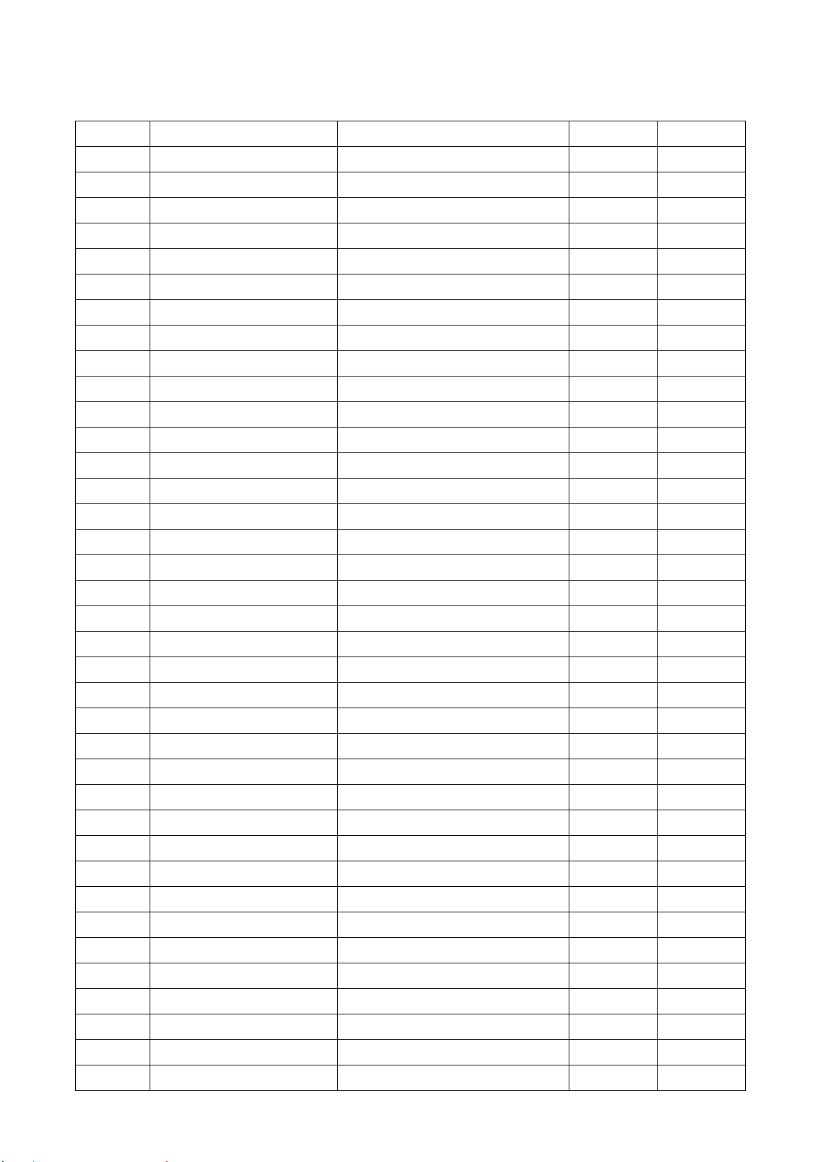
Location Part No. for TPV Description Quantity Unit
45G 76 28 H PE BAG FOR MANUAL 1 PCS
M1G 330 6128 SCREW 1 PCS
CBPC780KAXHP CONVERSION BOARD 1 PCS
KEPC780KC7 KEY BOARD 1 PCS
PWPC1742AUH1 POWER BOARD 1 PCS
S95G80183042 LVDS ASS'Y 1 PCS
12G6059 1 RUBBER 1 PCS
15G5689 3 A GROUND CLAMP 1 PCS
15G8006 1 MAIN FRAME 1 PCS
34G1310 EY B REAR COVER 1 PCS
34G1311 EY 2B LOGO COVER(HP) 1 PCS
40G 190690 9H ID LABEL 1 PCS
HP L1702
40G 45769017A s/n label 60x15mm 1 PCS
40G 457716 1A TCO99 LABEL 1 PCS
40G 459690 2A TAIWAN LABEL FOR 1702 1 PCS
40G 459690 5A HP EXTRA CARTON LABEL 1 PCS
40G 581716 3A CARTON LABEL 1.01 PCS
41G160069029C DOC KIT 1702 FOR APD 1 PCS
41G780069050A QSP 1 PCS
41G780069071A VESA COVER RTFCARD 1 PCS
41G7800690A04 RESOLUTION CARD 1 PCS
44G3731 P1 WO CARD BOARD 1 PCS
44G3731690 1D CARTON 1 PCS
44G3732 1 EPS 1 PCS
44G3732 2 EPS 1 PCS
45G 76 28 H PE BAG FOR MANUAL 1 PCS
45G 88609 2 EPE COVER 1 PCS
45G 88626 H PE BAG FOR MONITOR 1 PCS
52G 1185 MIDDLE TAPE FOR CARTON 120 CM
52G 1186 SMALL TAPE 8 CM
52G6022 3 SMALL TAPE 15 CM
52G6025 11523 INSULATE SHEET 1 PCS
52G6025 11657 INSULATE SHEET 1 PCS
95G8014 16 23 WIRE HARNESS 1 PCS
96G 29 8 TUBE 10 MM
M1G 330 4128 SCREW M3X4 6 PCS
M1G1140 6128 SCREW 4X6 1 PCS
36
Page 37
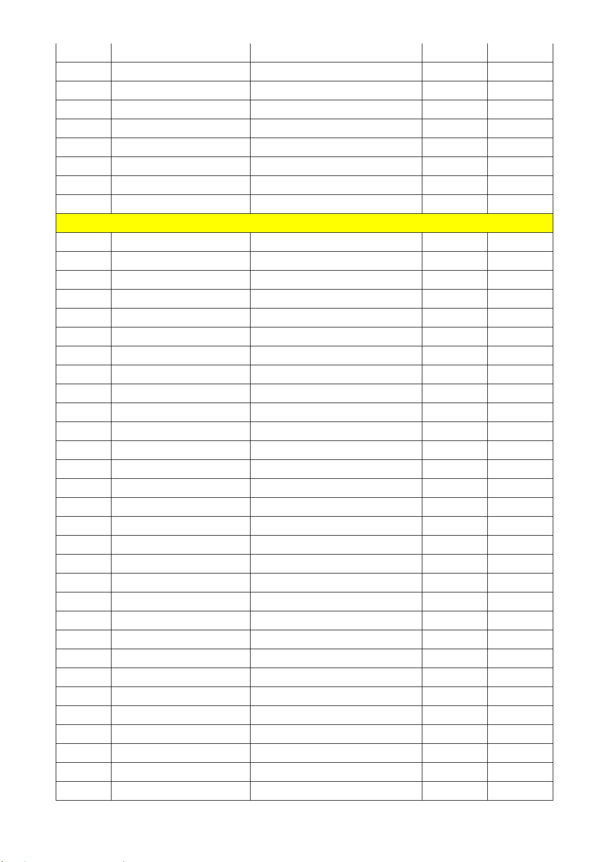
HP L1702
M1G1730 6128 SCREW M3x6 9 PCS
Q1G 330 8120 SCREW 3X8mm 3 PCS
Q1G 340 10 47 SCREW 2 PCS
Q1G1030 8128 SCREW 2 PCS
705L780KP87 01 AC SOCKET ASS'Y 1 PCS
AM1G1740 12 47 SCREW 2 PCS
E089A 89G402A19N IS AC POWER CABLE 1 PCS
E089B 89G1735LAA 13 SIGNAL CABLE 1 PCS
E750L 750LLU70N05 1 AU 17" EN05 V2 PANEL 1 PCS
CBPC780KAXHP
AIC780KAXHP MAIN BOARD 1 PCS
40G 45762412B CBPC LABEL 1 PCS
C204 67G215V221 4R LOW E.S.R 220UF +/-20% 1 PCS
C208 67G309V100 4 10UF +-20% 25V 1 PCS
C211 67G215B4704KV 47uF/25V 1 PCS
C215 67G215L101 4R LOW E.S.R 100UF +/-20% 1 PCS
C402 67G309V100 4 10UF +-20% 25V 1 PCS
C411 67G309V100 4 10UF +-20% 25V 1 PCS
C416 67G309V100 4 10UF +-20% 25V 1 PCS
C419 67G309V100 4 10UF +-20% 25V 1 PCS
C422 67G309V100 4 10UF +-20% 25V 1 PCS
C428 67G309V100 4 10UF +-20% 25V 1 PCS
CN201 33G8027 12 WAFER 2*6P 2.0MM R/A 1 PCS
CN303 33G8027 14 H WAFER 14P 2.0MM DIP 1 PCS
CN503 33G801724E H WAFER 1 PCS
CN602 33G8027 16 WAFER 16PIN 2.0mm DIP 1 PCS
X401 93G 22 53 CRYSTAL 14.318MHzHC-49U 1 PCS
X601 93G 22 51 CRYSTAL 12MHz HC-49US A 1 PCS
40G 457624 1B LABEL-CPU 1 PCS
715L1253 1 MAIN BOARD 1 PCS
C201 65G0603104 32 CHIP 0.1UF 50V X7R 1 PCS
C205 65G0603104 32 CHIP 0.1UF 50V X7R 1 PCS
C207 65G0603104 32 CHIP 0.1UF 50V X7R 1 PCS
C210 65G0603104 32 CHIP 0.1UF 50V X7R 1 PCS
C212 65G0603104 32 CHIP 0.1UF 50V X7R 1 PCS
C214 65G0603104 32 CHIP 0.1UF 50V X7R 1 PCS
C216 65G0603104 32 CHIP 0.1UF 50V X7R 1 PCS
C217 65G0603104 32 CHIP 0.1UF 50V X7R 1 PCS
C302 65G0603473 32 CHIP 0.047UF 50V X7R 1 PCS
C303 65G0603473 32 CHIP 0.047UF 50V X7R 1 PCS
37
Page 38

HP L1702
C304 65G0603473 32 CHIP 0.047UF 50V X7R 1 PCS
C305 65G0603102 32 1000PF +-10% 50V X7R 1 PCS
C308 65G0603473 32 CHIP 0.047UF 50V X7R 1 PCS
C309 65G0603473 32 CHIP 0.047UF 50V X7R 1 PCS
C310 65G0603473 32 CHIP 0.047UF 50V X7R 1 PCS
C311 65G0603470 31 CHIP 47PF 50V NPO 1 PCS
C312 65G0603221 31 CER1 0603 NP0 50V 220P 1 PCS
C313 65G0603104 32 CHIP 0.1UF 50V X7R 1 PCS
C401 65G0603104 32 CHIP 0.1UF 50V X7R 1 PCS
C403 65G0603104 32 CHIP 0.1UF 50V X7R 1 PCS
C404 65G0603104 32 CHIP 0.1UF 50V X7R 1 PCS
C405 65G0603104 32 CHIP 0.1UF 50V X7R 1 PCS
C406 65G0603104 32 CHIP 0.1UF 50V X7R 1 PCS
C407 65G0603104 32 CHIP 0.1UF 50V X7R 1 PCS
C409 65G0603104 32 CHIP 0.1UF 50V X7R 1 PCS
C410 65G0603104 32 CHIP 0.1UF 50V X7R 1 PCS
C412 65G0603104 32 CHIP 0.1UF 50V X7R 1 PCS
C413 65G0603104 32 CHIP 0.1UF 50V X7R 1 PCS
C414 65G0603104 32 CHIP 0.1UF 50V X7R 1 PCS
C415 65G0603104 32 CHIP 0.1UF 50V X7R 1 PCS
C417 65G0603104 32 CHIP 0.1UF 50V X7R 1 PCS
C418 65G0603104 32 CHIP 0.1UF 50V X7R 1 PCS
C420 65G0603104 32 CHIP 0.1UF 50V X7R 1 PCS
C421 65G0603104 32 CHIP 0.1UF 50V X7R 1 PCS
C423 65G0603104 32 CHIP 0.1UF 50V X7R 1 PCS
C424 65G0603104 32 CHIP 0.1UF 50V X7R 1 PCS
C425 65G0603104 32 CHIP 0.1UF 50V X7R 1 PCS
C426 65G0603220 31 CER1 0603 NP0 50V 22P P 1 PCS
C427 65G0603220 31 CER1 0603 NP0 50V 22P P 1 PCS
C429 65G0603104 32 CHIP 0.1UF 50V X7R 1 PCS
C510 65G0603104 32 CHIP 0.1UF 50V X7R 1 PCS
C511 65G0603104 32 CHIP 0.1UF 50V X7R 1 PCS
C601 65G0603104 32 CHIP 0.1UF 50V X7R 1 PCS
C602 65G0603220 31 CER1 0603 NP0 50V 22P P 1 PCS
C604 65G0603220 31 CER1 0603 NP0 50V 22P P 1 PCS
C605 65G0603104 32 CHIP 0.1UF 50V X7R 1 PCS
C606 65G0603104 32 CHIP 0.1UF 50V X7R 1 PCS
C607 65G0603104 32 CHIP 0.1UF 50V X7R 1 PCS
C608 65G0603104 32 CHIP 0.1UF 50V X7R 1 PCS
C609 65G0603104 32 CHIP 0.1UF 50V X7R 1 PCS
38
Page 39

HP L1702
C610 65G0603104 32 CHIP 0.1UF 50V X7R 1 PCS
C614 65G0603104 32 CHIP 0.1UF 50V X7R 1 PCS
D201 93G2004 2A SM240A DO-214AC 1 PCS
D202 93G3020 19 ES3D 3A 1 PCS
D203 93G 6433P BAV99 SOT-23 1 PCS
D204 93G 39S 31 T MLL5236B 1 PCS
D205 93G 39S 30 T MLL5228B 1 PCS
D206 93G 39S 30 T MLL5228B 1 PCS
D301 93G 6433P BAV99 SOT-23 1 PCS
D302 93G 6433P BAV99 SOT-23 1 PCS
D303 93G 6433P BAV99 SOT-23 1 PCS
D304 93G 64 42 P BAV70 SOT-23 1 PCS
D305 93G 39147 TZMC5V6 1 PCS
D306 93G 39147 TZMC5V6 1 PCS
D307 93G 39147 TZMC5V6 1 PCS
D308 93G 39147 TZMC5V6 1 PCS
D309 93G 39147 TZMC5V6 1 PCS
D327 93G 39147 TZMC5V6 1 PCS
D328 93G 39147 TZMC5V6 1 PCS
D329 93G 39147 TZMC5V6 1 PCS
FB202 71G 56Z601 CHIP BEAD 600 OHM 0805 1 PCS
FB301 71G 59C300 CHIP BEAD 1 PCS
FB302 71G 59C300 CHIP BEAD 1 PCS
FB303 71G 59C300 CHIP BEAD 1 PCS
FB304 61L0603151 CHIPR 150 OHM +-5% 1/10 1 PCS
FB401 71G 56Z601 CHIP BEAD 600 OHM 0805 1 PCS
FB402 71G 56Z601 CHIP BEAD 600 OHM 0805 1 PCS
FB403 71G 56Z601 CHIP BEAD 600 OHM 0805 1 PCS
FB404 71G 56Z601 CHIP BEAD 600 OHM 0805 1 PCS
FB405 71G 56Z601 CHIP BEAD 600 OHM 0805 1 PCS
FB406 71G 56Z601 CHIP BEAD 600 OHM 0805 1 PCS
Q201 57G 417 4 PMBS3904/PHILIPS-SMT(04 1 PCS
Q202 57G 417 4 PMBS3904/PHILIPS-SMT(04 1 PCS
Q203 57G 763 1 A03401 SOT23 BY AOS(A1) 1 PCS
Q204 57G 417 4 PMBS3904/PHILIPS-SMT(04 1 PCS
Q601 57G 417 6 PMBS3906/PHILIPS-SMT(06 1 PCS
Q602 57G 417 6 PMBS3906/PHILIPS-SMT(06 1 PCS
R201 61L0603000 RST SM 0603 JUMP MAX 0R 1 PCS
R202 61L0603103 RST SM 0603 RC0603 10K 1 PCS
R203 61L0603102 RST SM 0603 RC0603 1K P 1 PCS
39
Page 40

HP L1702
R204 61L0603102 RST SM 0603 RC0603 1K P 1 PCS
R205 61L0603472 RST SM 0603 RC0603 4K7 1 PCS
R206 61L0603103 RST SM 0603 RC0603 10K 1 PCS
R207 61L0603472 RST SM 0603 RC0603 4K7 1 PCS
R208 61L0603103 RST SM 0603 RC0603 10K 1 PCS
R209 61L0603000 RST SM 0603 JUMP MAX 0R 1 PCS
R211 61L0603103 RST SM 0603 RC0603 10K 1 PCS
R212 61L0603472 RST SM 0603 RC0603 4K7 1 PCS
R213 61L0603103 RST SM 0603 RC0603 10K 1 PCS
R301 61L0603750 RST SM 0603 RC22H 75R P 1 PCS
R302 61L0603750 RST SM 0603 RC22H 75R P 1 PCS
R303 61L0603750 RST SM 0603 RC22H 75R P 1 PCS
R304 61L0603750 RST SM 0603 RC22H 75R P 1 PCS
R305 61L0603471 CHIPR 470 OHM+-5% 1/10W 1 PCS
R306 61L0603750 RST SM 0603 RC22H 75R P 1 PCS
R307 61L0603750 RST SM 0603 RC22H 75R P 1 PCS
R308 61L0603101 RST SM 0603 RC0603 100R 1 PCS
R309 61L0603101 RST SM 0603 RC0603 100R 1 PCS
R310 61L0603101 RST SM 0603 RC0603 100R 1 PCS
R311 61L0603103 RST SM 0603 RC0603 10K 1 PCS
R312 61L0603101 RST SM 0603 RC0603 100R 1 PCS
R313 61L0603151 CHIPR 150 OHM +-5% 1/10 1 PCS
R314 61L0603101 RST SM 0603 RC0603 100R 1 PCS
R315 61L0603102 RST SM 0603 RC0603 1K P 1 PCS
R316 61L0603222 RST SM 0603 RC0603 2K2 1 PCS
R317 61L0603103 RST SM 0603 RC0603 10K 1 PCS
R318 61L0603472 RST SM 0603 RC0603 4K7 1 PCS
R319 61L0603472 RST SM 0603 RC0603 4K7 1 PCS
R320 61L0603470 RST SM 0603 RC0603 47R 1 PCS
R321 61L0603470 RST SM 0603 RC0603 47R 1 PCS
R351 61L0603000 RST SM 0603 JUMP MAX 0R 1 PCS
R355 61L0603000 RST SM 0603 JUMP MAX 0R 1 PCS
R357 61L0603000 RST SM 0603 JUMP MAX 0R 1 PCS
R358 61L0603000 RST SM 0603 JUMP MAX 0R 1 PCS
R359 61L0603000 RST SM 0603 JUMP MAX 0R 1 PCS
R401 61L0603390 0F CHIP 390 OHM 1/10W 1% 1 PCS
R402 61L0603472 RST SM 0603 RC0603 4K7 1 PCS
R403 61L0603472 RST SM 0603 RC0603 4K7 1 PCS
R501 61L0603202 CHIPR 2K OHM+-5% 1/10W 1 PCS
R502 61L0603000 RST SM 0603 JUMP MAX 0R 1 PCS
40
Page 41

HP L1702
R601 61L0603103 RST SM 0603 RC0603 10K 1 PCS
R602 61L0603103 RST SM 0603 RC0603 10K 1 PCS
R604 61L0603103 RST SM 0603 RC0603 10K 1 PCS
R605 61L0603103 RST SM 0603 RC0603 10K 1 PCS
R606 61L0603103 RST SM 0603 RC0603 10K 1 PCS
R607 61L0603103 RST SM 0603 RC0603 10K 1 PCS
R608 61L0603101 RST SM 0603 RC0603 100R 1 PCS
R609 61L0603101 RST SM 0603 RC0603 100R 1 PCS
R610 61L0603221 RST SM 0603 RC0603 220R 1 PCS
R611 61L0603221 RST SM 0603 RC0603 220R 1 PCS
R613 61L0603103 RST SM 0603 RC0603 10K 1 PCS
R614 61L0603103 RST SM 0603 RC0603 10K 1 PCS
R616 61L0603472 RST SM 0603 RC0603 4K7 1 PCS
R617 61L0603471 CHIPR 470 OHM+-5% 1/10W 1 PCS
R618 61L0603471 CHIPR 470 OHM+-5% 1/10W 1 PCS
R619 61L0603472 RST SM 0603 RC0603 4K7 1 PCS
R621 71G 59B601 EA CHIP BEAD 600 OHM 1 PCS
R622 71G 59B601 EA CHIP BEAD 600 OHM 1 PCS
R623 71G 59B601 EA CHIP BEAD 600 OHM 1 PCS
R624 71G 59B601 EA CHIP BEAD 600 OHM 1 PCS
R630 71G 59B601 EA CHIP BEAD 600 OHM 1 PCS
R631 61L0603103 RST SM 0603 RC0603 10K 1 PCS
R636 61L0603101 RST SM 0603 RC0603 100R 1 PCS
R638 61L0603000 RST SM 0603 JUMP MAX 0R 1 PCS
R639 61L0603104 RST SM 0603 RC0603 100K 1 PCS
R642 61L0603103 RST SM 0603 RC0603 10K 1 PCS
R643 61L0603103 RST SM 0603 RC0603 10K 1 PCS
R644 61L0603103 RST SM 0603 RC0603 10K 1 PCS
RN601 61L 125103 8 CHIP AR 8P4R 10KOHM +-5 1 PCS
RN602 61L 125103 8 CHIP AR 8P4R 10KOHM +-5 1 PCS
RN603 61L 125103 8 CHIP AR 8P4R 10KOHM +-5 1 PCS
RN604 61L 125103 8 CHIP AR 8P4R 10KOHM +-5 1 PCS
U201 56G 585 7 RT9164-25PL 1 PCS
U202 56G 563 7 AIC1084-33PM 1 PCS
U203 56G 643 5A MAX810 STRG 1 PCS
U301 56G1133 20 AT24C02N-10SU-2.7 1 PCS
U401 56G 562 53 MST9111B PQFP-128 1 PCS
U601 56L1125543AP1 MYSON MTV512MV 1 PCS
U602 56G1133 24 AT24C16AN-10SU-2.7 1 PCS
KEPC780KC7
41
Page 42
HP L1702
AIK780KC7 KEY BOARD 1 PCS
CN101 33G3802 7H WAFER 1 PCS
DP1 81G 12 1D GP LED 1 PCS
SW1 77G 600 1GCJ TACT SWITCH TSPB-2-NP 1 PCS
SW2 77G 600 1GCJ TACT SWITCH TSPB-2-NP 1 PCS
SW3 77G 600 1GCJ TACT SWITCH TSPB-2-NP 1 PCS
SW4 77G 600 1GCJ TACT SWITCH TSPB-2-NP 1 PCS
715L1242 1 PCB 1 PCS
R101 61G 60210252T CFR 1K OHM +-5% 1/6W 1 PCS
R102 61G 60210252T CFR 1K OHM +-5% 1/6W 1 PCS
ZD101 93G 3973B52T HZ6B2-E 1 PCS
ZD102 93G 3973B52T HZ6B2-E 1 PCS
ZD103 93G 3973B52T HZ6B2-E 1 PCS
ZD104 93G 3973B52T HZ6B2-E 1 PCS
PWPC1742AUH1
PW1742AUH1SMT POWER BOARD FOR SMT 1 PCS
13G 13 3 CANOE CLIP 2 PCS
40G 45762420A ID LABEL 1.03 PCS
52G6025 11658 INSULATE SHEET 1 PCS
95G8021 12514 POWER HARNESS 1 PCS
705G 780 61 06 R903 ASS'Y 1 PCS
705L 780 57 48 Q903 ASS'Y 1 PCS
705L 780 93 10 D910,D911 ASS'Y 1 PCS
C201 67G215C1514KT 150UF +-20% 25V 1 PCS
C215 65G 3J3906ET 39PF 5% 3KV TDK 1 PCS
C216 65G 3J3906ET 39PF 5% 3KV TDK 1 PCS
C217 65G 3J3906ET 39PF 5% 3KV TDK 1 PCS
C218 65G 3J3906ET 39PF 5% 3KV TDK 1 PCS
C223 67G215C1514KT 150UF +-20% 25V 1 PCS
C226 65G 3J3906ET 39PF 5% 3KV TDK 1 PCS
C227 65G 3J3906ET 39PF 5% 3KV TDK 1 PCS
C228 65G 3J3906ET 39PF 5% 3KV TDK 1 PCS
C229 65G 3J3906ET 39PF 5% 3KV TDK 1 PCS
C901 65G305M2222BP 2200PF +-20% 1 PCS
C902 65G305M2222BP 2200PF +-20% 1 PCS
C903 63G107K334 U1 3300PF 1 PCS
C904 67G305S10114K
C911 63G107K224 US 56KOHM 5% 1/6W 1 PCS
C912 65G306M4722BP 4700PF +-20% 400VAC 1 PCS
C922 67G215L102 3R LOW E.S.R 1000UF +/-20% 1 PCS
E.C 105 CAP
42
1 PCS
Page 43

HP L1702
C923 67G215L102 3R LOW E.S.R 1000UF +/-20% 1 PCS
CN201 33G8020 4D U WAFER 1 PCS
CN202 33G8020 4D U WAFER 1 PCS
CN901 33G8029 5A H 3 PIN CONNECTOR 1 PCS
D901 93G 6026T52T RECTIFIER DIODE FR107 1 PCS
D902 93G 6038T52T FR103 1 PCS
DB901 93G 50460502 KBP206G 1 PCS
FB901 71G 55 29 FERRITE BEAD 1 PCS
IC902 56G 139 3A PC123Y22FZOF 1 PCS
L201 73G 253139 HA CHOKE COIL 1 PCS
L202 73G 253139 HA CHOKE COIL 1 PCS
L901 73L 174 26T1G LINE LILT 0.45MM 1 PCS
L903 73G 253 91 LS CHOKE BY LI SHIN 1 PCS
L904 73G 253 91 LS CHOKE BY LI SHIN 1 PCS
NR901 61G 58050 WT NTC 5 OHM 5A 1 PCS
PT201 80LL15T 7YSG X'FMR 1 PCS
PT202 80LL15T 7YSG X'FMR 1 PCS
Q209 57G 761 7 KTD1691P 1 PCS
Q210 57G 761 7 KTD1691P 1 PCS
Q211 57G 761 7 KTD1691P 1 PCS
Q212 57G 761 7 KTD1691P 1 PCS
R917 61G152M398 64 0.39 OHM 2W 1 PCS
T901 80LL17T 2 TG X'FMR 1 PCS
PW1742AUH1SMT
PWPC1742AUH1AI POWER BOARD 1 PCS
C204 65G0805105 22 CHIP 1UF 25V X7R 0805 1 PCS
C205 65G0805104 32 CHIP 0.1U 50V X7R 1 PCS
C206 65G0805104 32 CHIP 0.1U 50V X7R 1 PCS
C208 65G0805331 31 CHIP 330pF 50V NPO 1 PCS
C209 65G0805105 22 CHIP 1UF 25V X7R 0805 1 PCS
C210 65G0805105 22 CHIP 1UF 25V X7R 0805 1 PCS
C221 65G0805103 32 10NF/50V/0805/X7R 1 PCS
C222 65G0805103 32 10NF/50V/0805/X7R 1 PCS
C401 65G0805105 22 CHIP 1UF 25V X7R 0805 1 PCS
C403 65G0805332 32 3200PF/25V/X7R 1 PCS
C404 65G0805104 32 CHIP 0.1U 50V X7R 1 PCS
C405 65G0805472 32 4700PF/50V/0805/X7R 1 PCS
C406 65G0805332 32 3200PF/25V/X7R 1 PCS
C907 65G0805104 32 CHIP 0.1U 50V X7R 1 PCS
C908 65G0805104 32 CHIP 0.1U 50V X7R 1 PCS
43
Page 44

HP L1702
C909 65G0805104 32 CHIP 0.1U 50V X7R 1 PCS
C910 65G0805102 32 CHIP 1000P 50VX7R 0805 1 PCS
C926 65G0805104 32 CHIP 0.1U 50V X7R 1 PCS
C927 65G0805104 32 CHIP 0.1U 50V X7R 1 PCS
C929 65G0805104 32 CHIP 0.1U 50V X7R 1 PCS
C930 65G0805471 21 CHIP 470PF 25V NPO 1 PCS
D201 93G2004 2A SM240A DO-214AC 1 PCS
D202 93G2004 2A SM240A DO-214AC 1 PCS
D205 93G 6432P LL4148 1 PCS
D206 93G 6432P LL4148 1 PCS
D207 93G 6432P LL4148 1 PCS
D208 93G 6432P LL4148 1 PCS
D209 93G 6432P LL4148 1 PCS
D210 93G 6432P LL4148 1 PCS
D401 93G 6432P LL4148 1 PCS
D402 93G 6432P LL4148 1 PCS
D903 93G 6432P LL4148 1 PCS
IC401 56G 192 10 LM358DT 1 PCS
IC901 56G 379 33 SG6841SZ 1 PCS
Q201 57G 760 5B PDTC144WK SOT346 1 PCS
Q202 57G 760 4B PDTA144WK SOT346 1 PCS
Q203 57G 763 3 AO4411 SO-8 1 PCS
Q204 57G 763 3 AO4411 SO-8 1 PCS
Q205 57G 417 4 PMBS3904/PHILIPS-SMT(04 1 PCS
Q206 57G 417 4 PMBS3904/PHILIPS-SMT(04 1 PCS
Q207 57G 417 6 PMBS3906/PHILIPS-SMT(06 1 PCS
Q208 57G 417 6 PMBS3906/PHILIPS-SMT(06 1 PCS
Q401 57G 417 4 PMBS3904/PHILIPS-SMT(04 1 PCS
Q402 57G 759 2 RK7002 1 PCS
R204 61L0805103 CHIPR 10K OHM +-5% 1/8W 1 PCS
R205 61L0805473 CHIPR 47K OHM +-5% 1/8W 1 PCS
R206 61L0805473 CHIPR 47K OHM +-5% 1/8W 1 PCS
R208 61L08054 72 CHIRP 4.7K OHM +-5% 1/8 1 PCS
R209 61L08054 72 CHIRP 4.7K OHM +-5% 1/8 1 PCS
R210 61L0805333 CHIP 33KOHM 1% 1/8W 1 PCS
R211 61L0805333 CHIP 33KOHM 1% 1/8W 1 PCS
R212 61L0805392 CHIP 3.9K OHM 1/8W 1 PCS
R213 61L0805392 CHIP 3.9K OHM 1/8W 1 PCS
R214 61L0805222 CHIP 2.2KOHM 5% 0805 1/ 1 PCS
R215 61L0805222 CHIP 2.2KOHM 5% 0805 1/ 1 PCS
44
Page 45

HP L1702
R216 61L0805220 CHIP 22 OHM 5% 0805 1/8 1 PCS
R217 61L0805220 CHIP 22 OHM 5% 0805 1/8 1 PCS
R218 61L0805220 CHIP 22 OHM 5% 0805 1/8 1 PCS
R219 61L0805220 CHIP 22 OHM 5% 0805 1/8 1 PCS
R220 61L0805153 CHIPR 15K OHM+-5% 1/8W 1 PCS
R221 61L0805153 CHIPR 15K OHM+-5% 1/8W 1 PCS
R222 61L0805123 CHIP 12KOHM 1/8W 1 PCS
R223 61L0805123 CHIP 12KOHM 1/8W 1 PCS
R224 61L1206152 CHIPR 1.5K OHM+-5%1/4W 1 PCS
R225 61L1206152 CHIPR 1.5K OHM+-5%1/4W 1 PCS
R226 61L1206152 CHIPR 1.5K OHM+-5%1/4W 1 PCS
R227 61L1206152 CHIPR 1.5K OHM+-5%1/4W 1 PCS
R228 61L1206152 CHIPR 1.5K OHM+-5%1/4W 1 PCS
R229 61L1206152 CHIPR 1.5K OHM+-5%1/4W 1 PCS
R230 61L1206152 CHIPR 1.5K OHM+-5%1/4W 1 PCS
R231 61L1206152 CHIPR 1.5K OHM+-5%1/4W 1 PCS
R232 61L0805102 CHIPR 1K OHM +-5% 1/8W 1 PCS
R233 61L0805102 CHIPR 1K OHM +-5% 1/8W 1 PCS
R234 61L0805821 820 1/8W 1 PCS
R235 61L0805821 820 1/8W 1 PCS
R236 61L0805431 CHIP 430OHM 5% 0805 1/8 1 PCS
R237 61L0805431 CHIP 430OHM 5% 0805 1/8 1 PCS
R238 61L0805123 CHIP 12KOHM 1/8W 1 PCS
R239 61L0805123 CHIP 12KOHM 1/8W 1 PCS
R240 61L0805513 CHIP 51KOHM 1/8W 1 PCS
R241 61L0805513 CHIP 51KOHM 1/8W 1 PCS
R242 61L0805682 CHIP 6.8KOHM 5% 0805 1/ 1 PCS
R401 61L0805102 CHIPR 1K OHM +-5% 1/8W 1 PCS
R402 61L1206471 CHIPR 470 OHM+-5% 1/4W 1 PCS
R405 61L0805273 CHIP 27KOHM 5% 0805 1/8 1 PCS
R406 61L0805273 CHIP 27KOHM 5% 0805 1/8 1 PCS
R408 61L0805364 CHIP 360KOHM 5% 0805 1/ 1 PCS
R409 61L0805104 CHIPR 100K OHM+-5% 1/8W 1 PCS
R410 61L0805134 CHIP 130KOHM+-5% 1/8W 1 PCS
R414 61L0805223 CHIP 22KOHM 1/8W 1 PCS
R415 61L0805333 CHIP 33KOHM 1% 1/8W 1 PCS
R416 61L0805333 CHIP 33KOHM 1% 1/8W 1 PCS
R900 61L1206394 CHIPR 390KOHM+-5% 1/4W 1 PCS
R901 61L1206394 CHIPR 390KOHM+-5% 1/4W 1 PCS
R902 61L1206394 CHIPR 390KOHM+-5% 1/4W 1 PCS
45
Page 46
HP L1702
R904 61L1206105 CHIP 1MOHM 5% 1/4W 1 PCS
R905 61L1206105 CHIP 1MOHM 5% 1/4W 1 PCS
R906 61L1206105 CHIP 1MOHM 5% 1/4W 1 PCS
R907 61L1206105 CHIP 1MOHM 5% 1/4W 1 PCS
R908 61L1206519 CHIPR 5.1OHM +-5% 1/4W 1 PCS
R909 61L08054 72 CHIRP 4.7K OHM +-5% 1/8 1 PCS
R910 61L08054 72 CHIRP 4.7K OHM +-5% 1/8 1 PCS
R911 61L0805472 CHIRP 4.7K OHM +-5% 1/8 1 PCS
R912 61L0805101 CHIPR 100 OHM +-5% 1/8W 1 PCS
R913 61L0805103 CHIPR 10K OHM +-5% 1/8W 1 PCS
R914 61L0805240 2F CHIP 24KOHM 1% 1/8W 1 PCS
R915 61L0805220 CHIP 22 OHM 5% 0805 1/8 1 PCS
R916 61L0805103 CHIPR 10K OHM +-5% 1/8W 1 PCS
R924 61L0805242 CHIP 2.4KOHM 1% 1/8W 1 PCS
R925 61L0805102 CHIPR 1K OHM +-5% 1/8W 1 PCS
R926 61L0805102 CHIPR 1K OHM +-5% 1/8W 1 PCS
R927 61L0805000 CHIP O OHM 1/8W 1 PCS
R928 61L0805102 CHIPR 1K OHM +-5% 1/8W 1 PCS
R929 61L1206101 CHIP 100 OHM 5% 1/4W 1 PCS
R932 61L0805221 CHIPR 220 OHM +-5% 1/8W 1 PCS
U201 56G 608 1 TL1451ACD 1 PCS
ZD203 93G 39S 3 T BZT52-C11 1 PCS
ZD204 93G 39S 3 T BZT52-C11 1 PCS
ZD401 93G 39S 24 T RLZ 5.6B LLDS 1 PCS
ZD901 93G 39S 23 T GLZ22B 1 PCS
ZD904 93G 39S 19 T PTZ7.5B 1 PCS
715L1236 2 AU POWER BOARD 1 PCS
C207 67G 305330 7T
C903 6G 31502 1.5MM RIVET 2 PCS
C904 6G 31502 1.5MM RIVET 2 PCS
C905 65G 2K152 1T6921 1.5NF/2KV Y5P +-10% 1 PCS
33UF 105
1 PCS
C920 65G517K102 5T 1000PF 10% Y5P 500V 1 PCS
C921 65G517K102 5T 1000PF 10% Y5P 500V 1 PCS
CN901 6G 31500 EYELET 3 PCS
F901 84G 56 1 FUSE 2A 250V WICKMANN 1 PCS
IC903 56G 158 4 T H431BA 1 PCS
L901 6G 31502 1.5MM RIVET 4 PCS
NR901 6G 31502 1.5MM RIVET 2 PCS
PT201 6G 31502 1.5MM RIVET 2 PCS
PT202 6G 31502 1.5MM RIVET 2 PCS
46
Page 47

HP L1702
Q901 57G 420 PP T 2PA733P 1 PCS
Q902 57G 419 PP T 2PC945P 1 PCS
R404 61G 60256352T 56KOHM 5% 1/6W 1 PCS
R407 61G 60247452T 470K OHM 5% 1/6W 1 PCS
R411 61G 60216452T 160K OHM 5% 1/6W 1 PCS
R920 61G175L47052T 47OHM +-5% 1/2W 1 PCS
R921 61G175L47052T 47OHM +-5% 1/2W 1 PCS
R922 61G 21033352T 33K 1/6W 1% 1 PCS
R923 61G 21036252T 3.6K 1/6W 1% 1 PCS
T901 6G 31502 1.5MM RIVET 4 PCS
ZD902 93G 39 5452T HZ12B2-E 1 PCS
ZD903 93G 39 7752T HZ5C1-E 1 PCS
96G 29 6 SHRINK TUBE UL/CSA 1 PCS
R903 61G152M10458F 100K OHM 5% 2W 1 PCS
90G6064 1 HEAT SINK 1 PCS
M1G1730 8128 SCREW M3x8 1 PCS
Q903 57G 600 35 STP8NK80ZFP 1 PCS
90G6064 1 HEAT SINK 1 PCS
M1G1730 8128 SCREW M3x8 2 PCS
D910 93G 60245 SP10150 1 PCS
D911 93G 60237 SRF20100C 1 PCS
33F 206 24 DF11-24DS-2C 1 PCS
33F 303 30TD1 TD00-30H P2407P30 1 PCS
33F206T 24 DF11-2428SCF 24 PCS
33F303TTD1 TD00-T 24 PCS
15G8007 1 BASE BKT 1 PCS
33G4617 1 POWER LENS 1 PCS
33G4725 FE L OSD BUTTON 1 PCS
34G1309AA5 B BEZEL 1 PCS
Q1G 130 6120 SCREW (T3X6) 6 PCS
T34G1314 EY B BASE 1 PCS
M037 37G6014 GC N HINGE 1 PCS
2F0605100
4F0612052 00 METAL WASHER 1 PCS
4F061210T 00 METAL WASHERS12.0*8.00* 2 PCS
4F061820P 00 WASHER 2 PCS
4F0818052 00 WASHER 4 PCS
15F6014110 BRACKET 1 PCS
27F0610310 BUSHING 1 PCS
28F0653080 SHAFT 1 PCS
SCREW NUTS M6.0*P1.0 フ
47
1 PCS
Page 48

HP L1702
33F4726 EY 1B HINGE WHEEL 1 PCS
33F4726 EY 2B HINGE WHEEL 1 PCS
34F1312 EY B HINGE AXIS 1 PCS
34F1313 EY B STAND 1 PCS
Q1F 340 10 47 SCREW 4 PCS
15G8009 1 AC SUPPORT BRACKET 1 PCS
87G 501 13 RF AC SOCKET 1 PCS
95G205S354022 HARNESS 1 PCS
95G8021 2506 HARNESS 1 PCS
96G 29 6 SHRINK TUBE UL/CSA 1 PCS
48
Page 49

文件名: AOC Service Manual- HP L1702
目录: C:\Documents and Settings\qiufen.mao\My Documents
模板: C:\Documents and Settings\qiufen.mao\Application Data\Microsoft\Templates\Normal.dotm
标题:
主题:
作者: @
关键词:
备注:
创建日期: 2005-11-30 8:30:00
修订号: 1,243
上次保存日期: 2008-1-24 10:17:00
上次保存者: Administrator
编辑时间总计: 4,603 分钟
上次打印时间: 2008-1-24 10:17:00
打印最终结果
页数: 48
Page 50

字数: 5,481 (约)
字符数: 31,246 (约)
 Loading...