

Page 1
19" LCD Color Monitor AOC 913Fw
Service
Service
Service
Horizontal Frequency
30-80 kHz
TABLE OF CONTENTS
Description Page Description Page
Table Of Contents…………………………………………...1
Revision List………………………………………………....2
1. Monitor Specification..............................…………........3
2. LCD Monitor Description…………………………….......4
3. Operation Instructions....................................…...........5
3.1. General Instructions...........................…....................5
3.2. Control Button…………………………….…...............5
3.3 Adjusting the Picture...........................…..............6
4. Input/Output Specification............……………............8
4.1. Input Signal Connector............………….................8
4.2. Factory Preset Display Modes......….................. 8
4.3. Panel Specification.....………………..................9
5. Block Diagram….........................................................11
5.1 Software Flow Chart………………………….……….11
5.2.Electrical Block Diagram…………………….......13
6. Schematic……………..............................................15
6.1 Main Board....……….............................................15
6.2 Power Board………………………………………....19
7. PCB Layout..………….............................................21
7.1. Main Board………................................................21
7.2. Power Board….....................................................24
7.3. Key Board….........................................................26
8. Maintainability………...............................................27
8.1.Equipments and Tools Requirement......................27
8.2.Trouble Shooting………........................................28
9. White-Balance, Luminance adjustment………..…...34
10. Monitor Exploded View…………………….…........36
11. BOM List…............................................................37
12. Different Parts List.........…………..........................49
SAFETY NOTICE
ANY PERSON ATTEMPTING TO SERVICE THIS CHASSIS MUST FAMILIARIZE HIMSELF WITH THE CHASSIS
AND BE AWARE OF THE NECESSARY SAFETY PRECAUTIONS TO BE USED WHEN SERVICING
ELECTRONIC EQUIPMENT CONTAINING HIGH VOLTAGES.
CAUTION: USE A SEPARATE ISOLATION TRANSFOMER FOR THIS UNIT WHEN SERVICING
1
Page 2
19" LCD Color Monitor AOC 913Fw
Revision List
Version Date Revision History TPV Model Name
A00 Nov.-14-07 Initial release T97MMBNDLWA4NNE
A01 Dec.-13-07 Add TPVDW Model in Item 12
A02 Jan.-16-08 Add TPVDW Model in Item 12
T972MBNCLWA1NNE
T97MMBNKLWA1NNE
T97MMBNQLWA17NE
T97MMBNQLWA27NE
2
Page 3
19" LCD Color Monitor AOC 913Fw
Monitor Specification
Model number 913Fw
Driving system TFT Color LCD
Viewable Image Size 481mm diagonal
LCD Panel
Resolution
Pixel pitch 0.285mm(H) x 0.285mm(V)
Video R, G, B Analog interface
Separate Sync. H/V TTL
Display Color 16.2 million Colors
Dot Clock 135 MHz
Horizontal scan range 30 kHz - 80 KHz
Horizontal scan Size(Maximum) 427.7mm
Vertical scan range 55 Hz - 75 Hz
Vertical scan Size(Maximum) 277.9mm
Optimal preset resolution 1440 x 900 (60 Hz)
Highest preset resolution 1440 x 900 (75 Hz)
Plug & Play VESA DDC2B/CI
Input Connector D-Sub 15pin
Input Video Signal Analog: 0.7Vp-p(standard), 75 OHM, Positive
Power Source 100~240VAC, 47~63Hz
Active ≤37W
Physical
Characteristics
Environmental
Power Consumption
Connector Type 15-pin Mini D-Sub
Signal Cable Type Detachable
Dimensions & Weight:
Height (with base) 360 mm
Width 444 mm
Depth 35 mm
Weight (monitor only) 3.56 kg
Weight (with packaging) 4.57 kg
Temperature:
Operating 0° to 35°
Non-Operating -20°to 60°
Humidity:
Operating 10% to 85% (non-condensing)
Non-Operating 5% to 80% (non-condensing)
Altitude:
Standby ≤1W
Operating 0~ 3000m (0~ 10000 ft )
Non-Operating 0~ 5000m (0~ 15000 ft )
3
Page 4
19" LCD Color Monitor AOC 913Fw
(
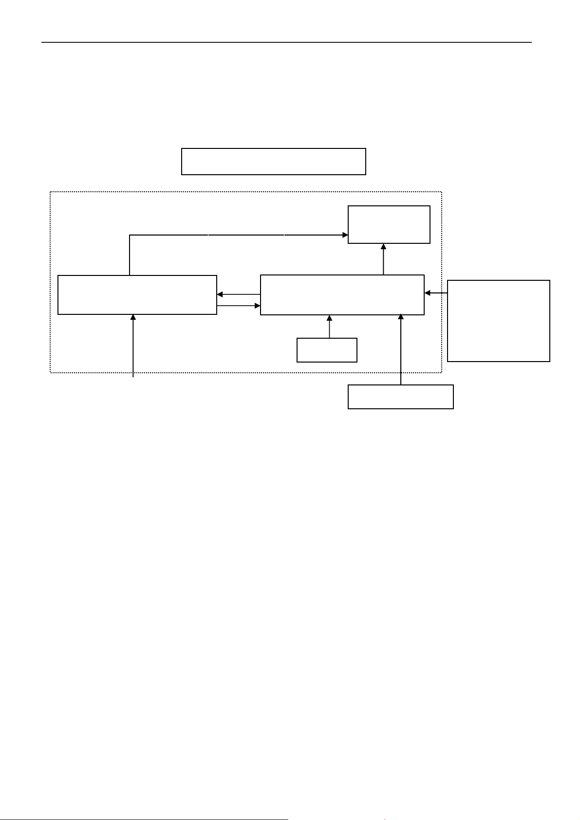
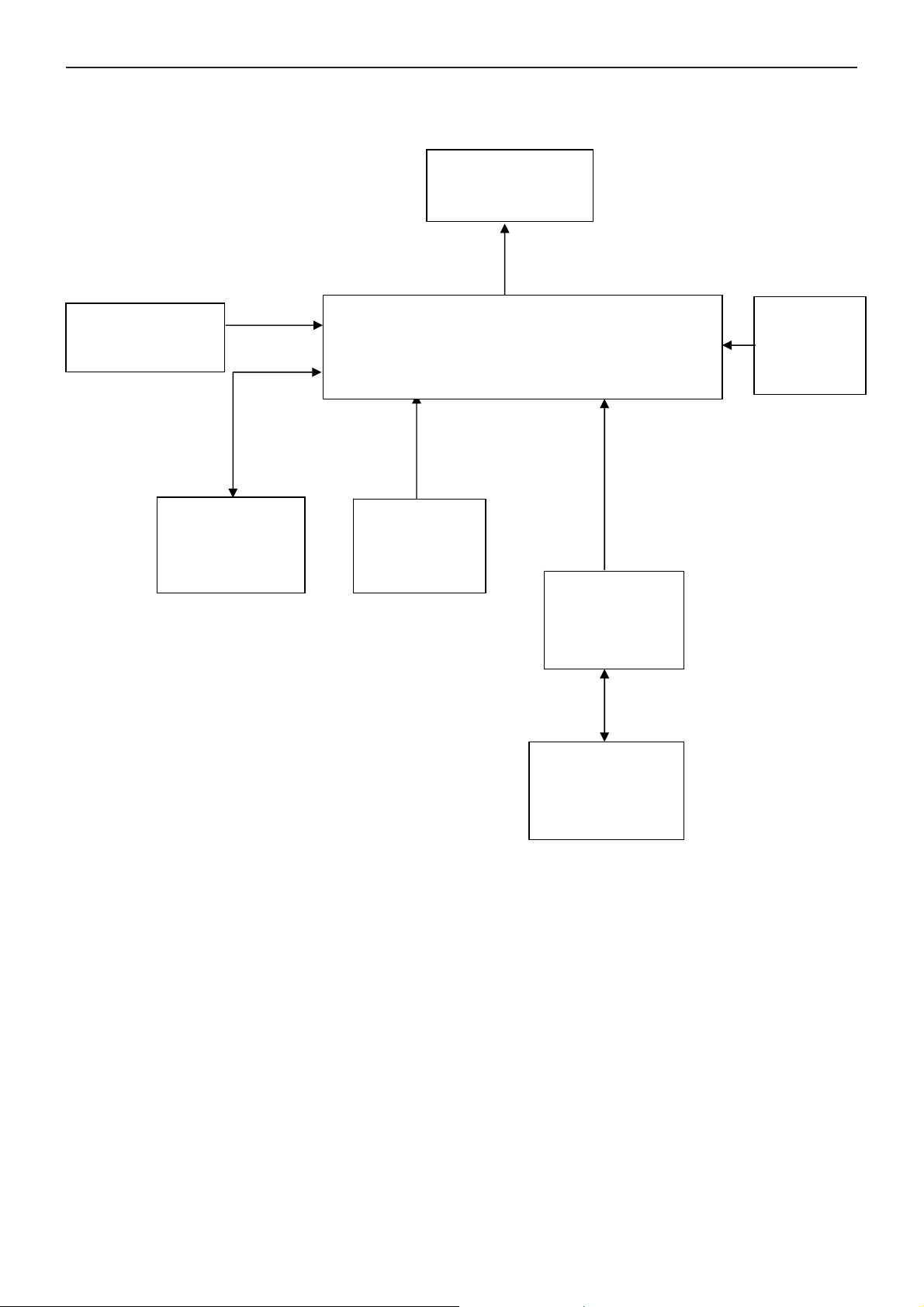
2. LCD Monitor Description
The LCD Monitor will contain main board, power board, key board which house the flat panel control logic,
brightness control logic and DDC.
The power board will provide AC to DC Inverter voltage to drive the backlight of panel and the main board chips
each voltage.
Include adapter and inverter)
Power Board
AC-IN
100V~240V
Monitor Block Diagram
CCFT Drive.
Main Board
Key board
Flat Panel and
CCFL backlight
RS232 Connector
For white balance
adjustment in
factory mode
Video signal, DDC
HOST Computer
4
Page 5
19" LCD Color Monitor AOC 913Fw
3. Operation Instructions
3.1 General Instructions
Press the power button to turn the monitor on or off. The control buttons are located at front panel of the monitor.
By changing these settings, the picture can be adjusted to your personal preferences.
The power cord should be connected.
-
Connect the video cable from the monitor to the video card.
-
Press the power button to turn on the monitor, the power indicator will light up.
-
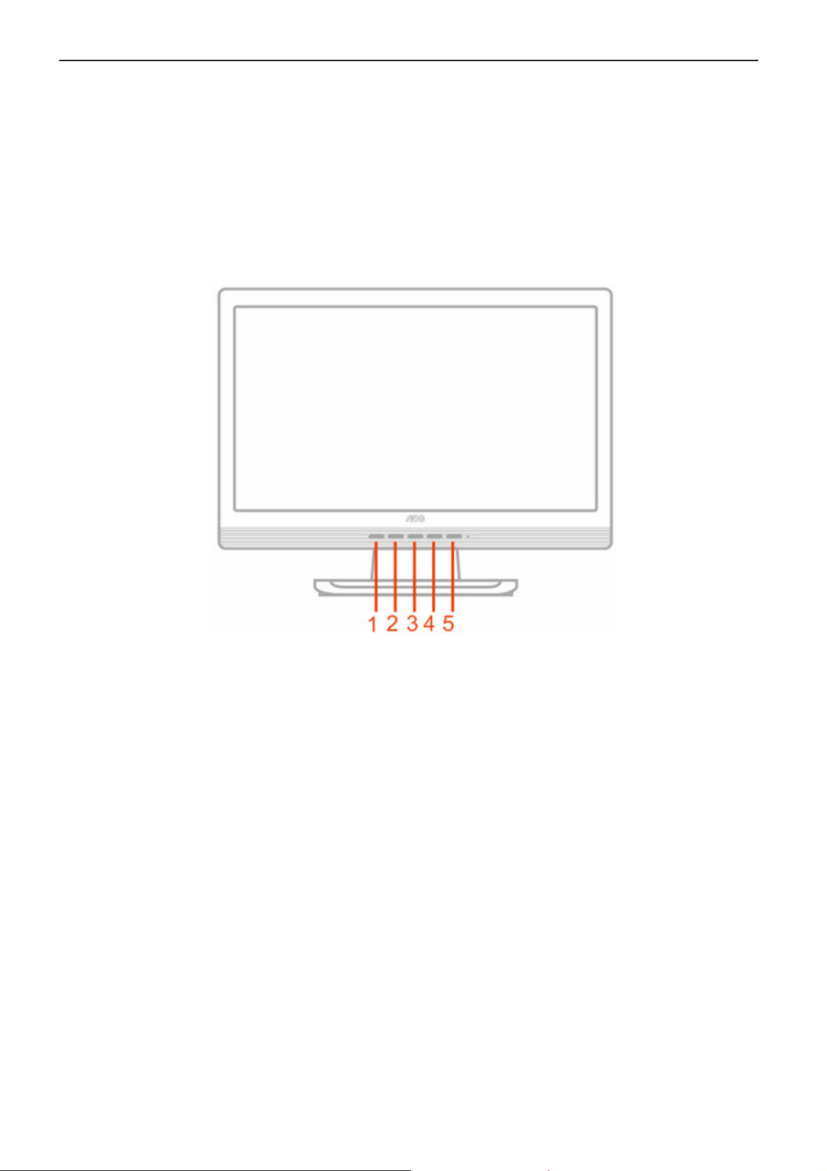
3.2 Control Buttons
1. Auto Config
2. Eco Mode/ down
3. Power Button & Indicator
4. Up
5. Menu / Enter
5
Page 6
19" LCD Color Monitor AOC 913Fw
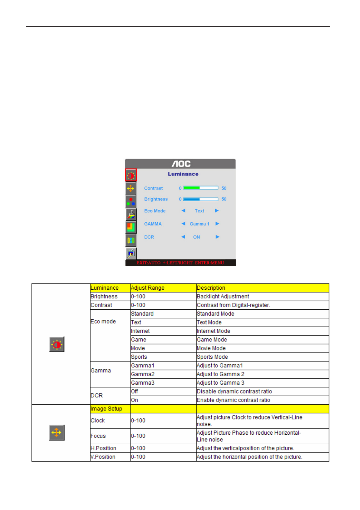
3.3 Adjusting the Picture
OSD Settings
• Press the MENU-button to activate the OSD window.
• Press+ or - to navigate through the functions. Once the desired function is highlighted, press the
MENU-button to activate it. If the function selected has a sub-menu, press or again to navigate through the
sub-menu functions. Once the desired function is highlighted, press MENU-button to activate it.
• Press+ or - to change the settings of the selected function. To exit and save, select the exit function. If you
want to adjust any other function, repeat steps 2-3.
• OSD Lock Function: To lock the OSD, press and hold the MENU button while the monitor is off and then
press power button to turn the monitor on. To un-lock the OSD - press and hold the MENU button while the
monitor is off and then press power button to turn the monitor on.
• Press Exit key continually for 7 sec. to turn on or off DDC-CI.
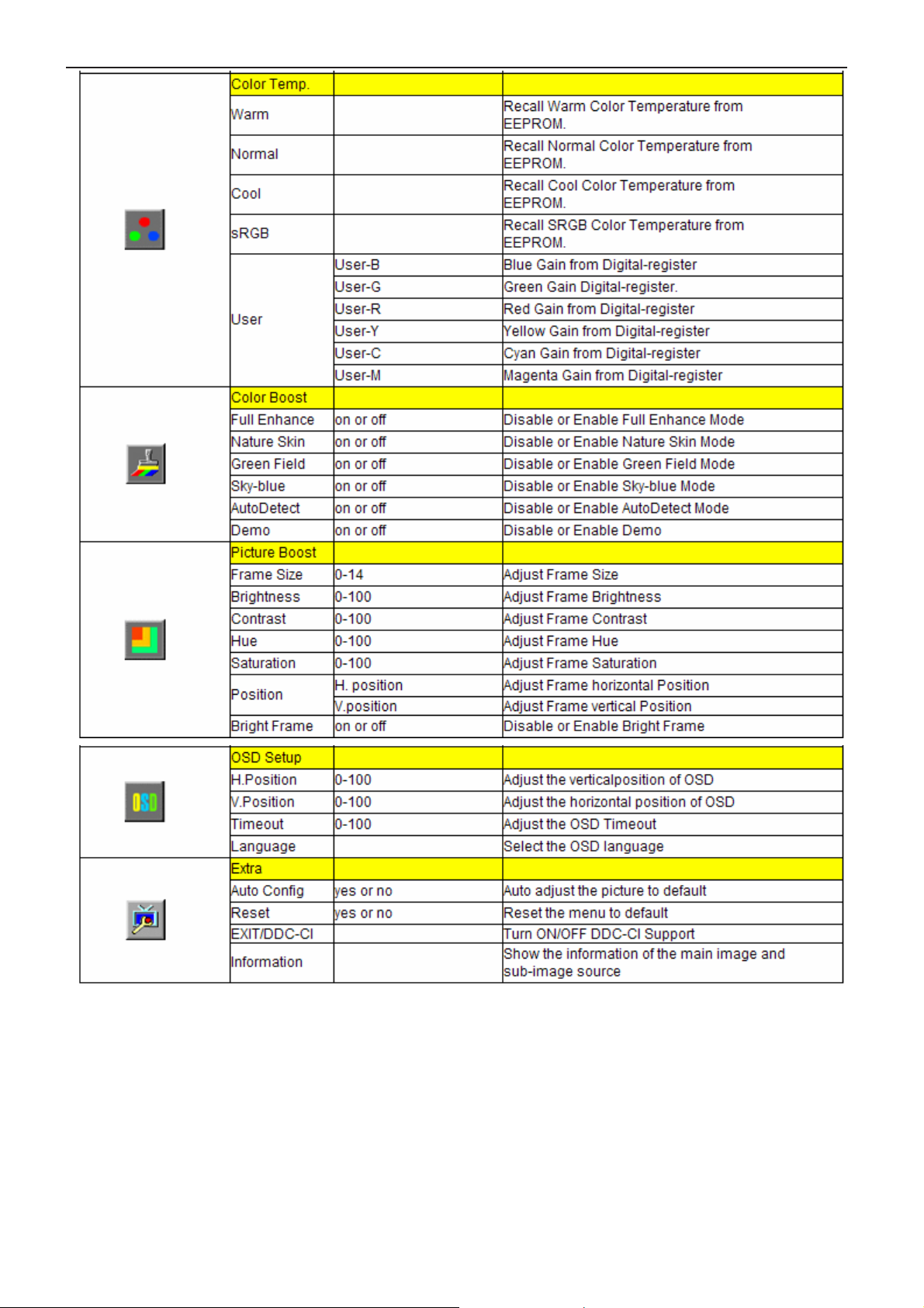
OSD functions
6
Page 7
19" LCD Color Monitor AOC 913Fw
7
Page 8
19" LCD Color Monitor AOC 913Fw
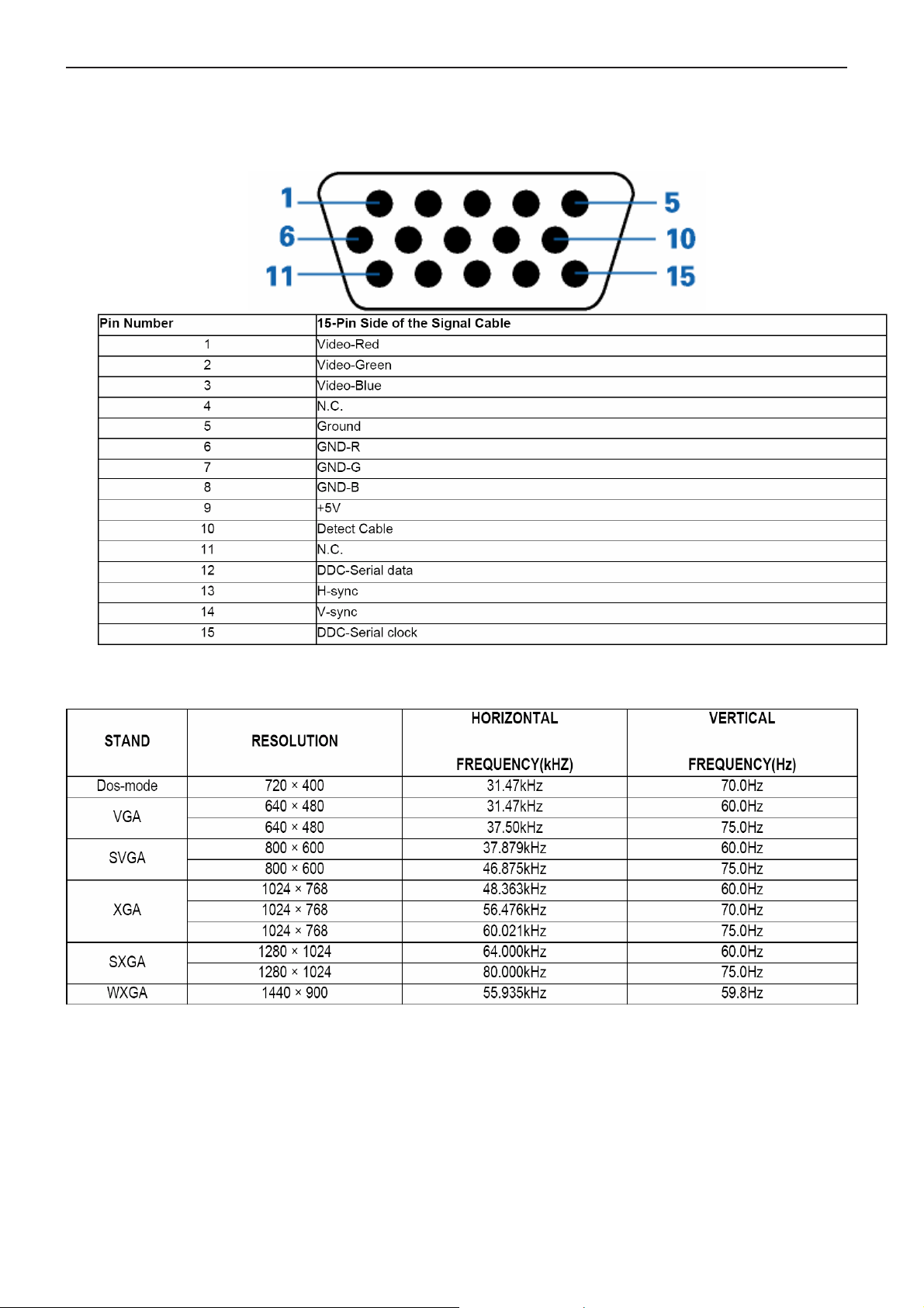
4. Input/Output Specification
4.1 Input Signal Connector
D-Sub mini 15pin Connector
4.2 Factory Preset Display Modes
8
Page 9
19" LCD Color Monitor AOC 913Fw
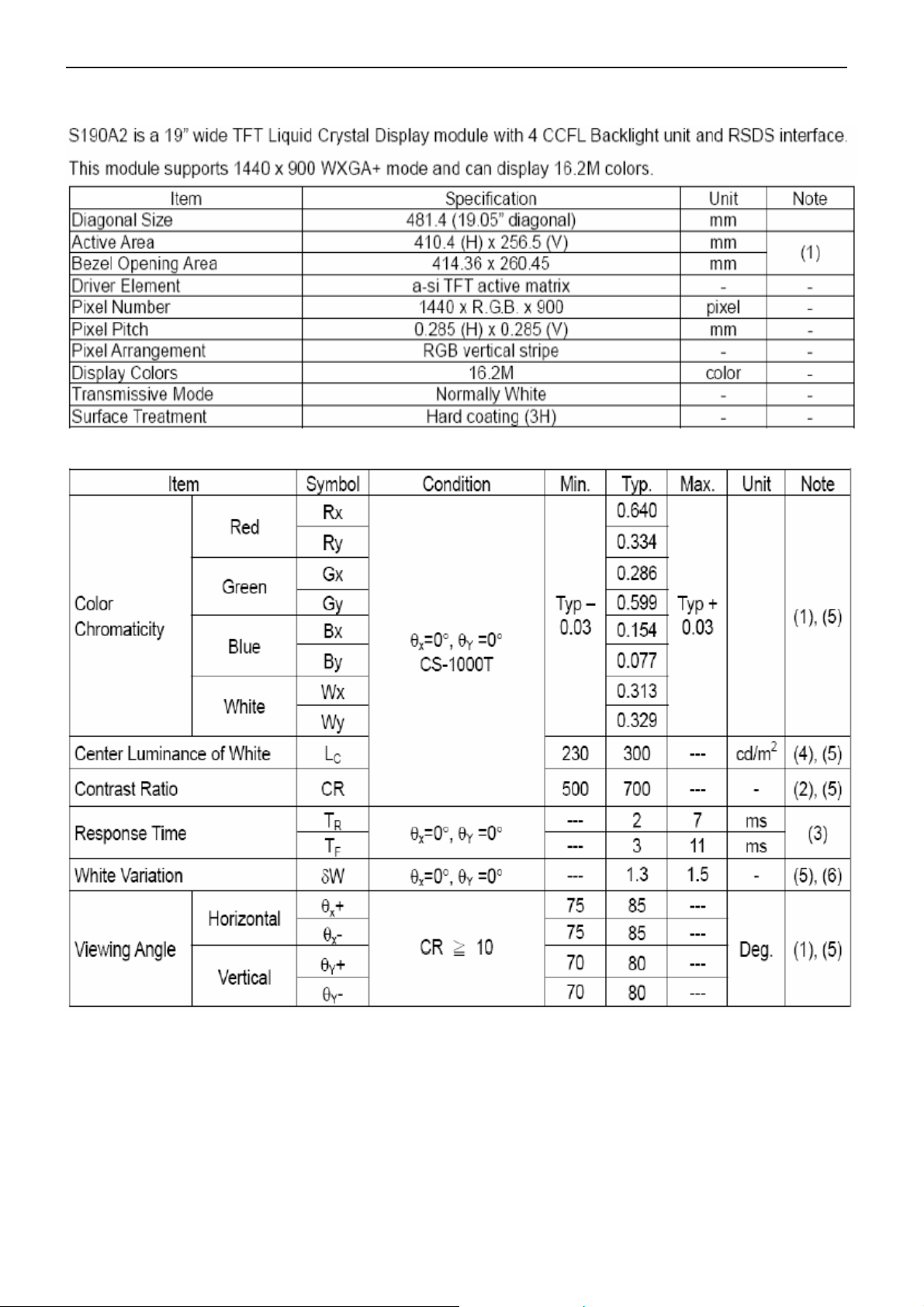
4.3. Panel Specification
4.3.1 General Feature
4.3.2 Optical Characteristics
9
Page 10
19" LCD Color Monitor AOC 913Fw
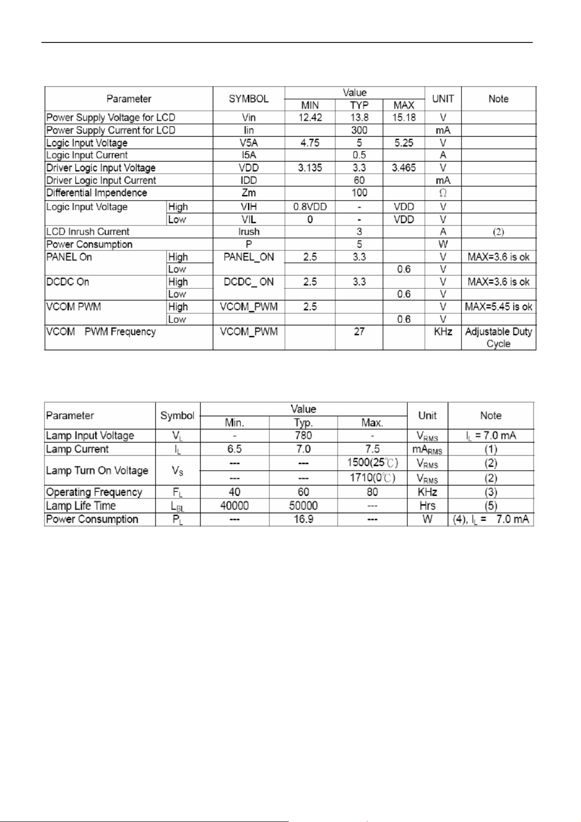
4.3.3 Electrical Characteristics
TFT Module
Back-light
10
Page 11
19" LCD Color Monitor AOC 913Fw
5. Block Diagram
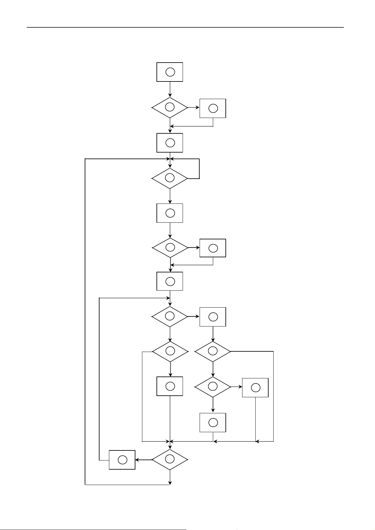
5.1 Software Flow Chart
1
Y
2
N
3
4
5
N
Y
6
N
7
8
Y
9
10
N
11
12
Y
13
N
N
Y
14
15
Y
N
16
Y
17
18
N
19
Y
11
Page 12
19" LCD Color Monitor AOC 913Fw
REMARK:
1) MCU initialize.
2) Is the EEprom blank?
3) Program the EEprom by default values.
4) Get the PWM value of brightness from EEprom.
5) Is the power key pressed?
6) Clear all global flags.
7) Are the AUTO and SELECT keys pressed?
8) Enter factory mode.
9) Save the power key status into EEprom.
Turn on the LED and set it to green color.
Scalar initialize.
10) In standby mode?
11) Update the lifetime of back light.
12) Check the analog port, are they’re any signals coming?
13) Does the scalar send out an interrupt request?
14) Wake up the scalar.
15) Are there any signals coming from analog port?
16) Display "No connection Check Signal Cable" message. And go into standby mode after the message
disappear.
17) Program the scalar to be able to show the coming mode.
18) Process the OSD display.
19) Read the keyboard. Is the power key pressed?
12
Page 13
19" LCD Color Monitor AOC 913Fw
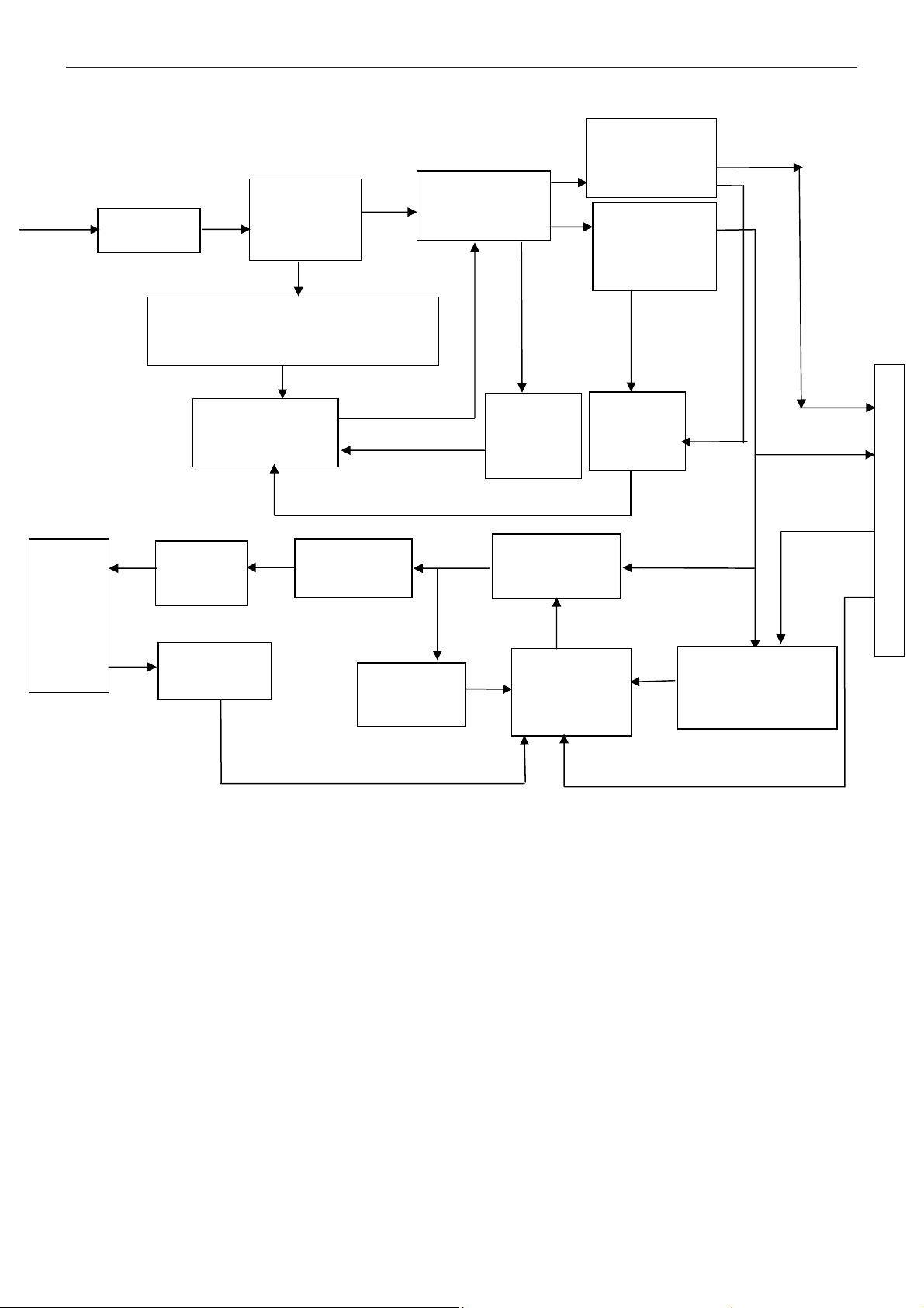
5.2 Electrical Block Diagram
Main Board
Keypad Interface
(CN403)
SDA
SCL
Flash Memory
PM25LV010A
(U402)
Panel Interface
Scalar TSUM17AWK-LF-1
(Include MCU, ADC, OSD)
Crystal
14.31818MHZ
(X401)
(CN7)
(U408)
EEPROM
M24C04
(U403)
H sync
V sync
RGB
D-Sub
Connector
(CN405)
VGA_SDA,
VGA_SCL
EEPROM
M24C02-WMN6TP
(U404)
13
Page 14
19" LCD Color Monitor AOC 913Fw
Power Board
5V Rectifier
and Filter
Lamp
EMI filter
Bridge
Rectifier and
Filter
Start Circuit: R904,R932,R933
PWM Control IC
IC TEA1530AT
Output
Circuit
Transformer
Transformer
T901
Over
Voltage
Protect
MOSFET
Q802,Q803
12V Rectifier
and Filter
Feedback
Circuit
CN902
5V
12V
ON/OFF
Feedback
Circuit
Over
Voltage
Protect
PWM Control
IC TL494IDR
ON/OFF Control
Q805/Q808
DIM Control
14
Page 15
19" LCD Color Monitor AOC 913Fw
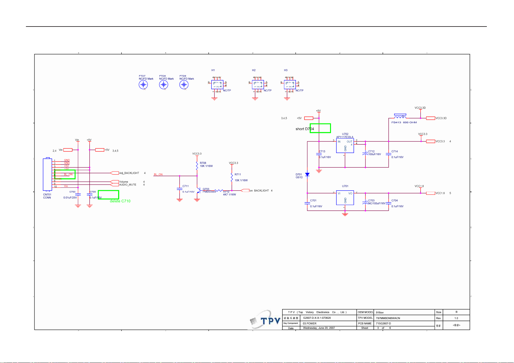
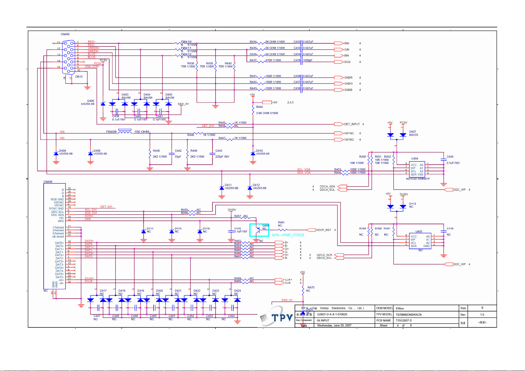
6. Schematic
6.1 Main Board
15
Page 16
19" LCD Color Monitor AOC 913Fw
16
Page 17

19" LCD Color Monitor AOC 913Fw
17
Page 18

19" LCD Color Monitor AOC 913Fw
18
Page 19

19" LCD Color Monitor AOC 913Fw
6.2 Power Board
19
Page 20

19" LCD Color Monitor AOC 913Fw
20
Page 21

19" LCD Color Monitor AOC 913Fw
7. PCB Layout
7.1 Main Board
21
Page 22

19" LCD Color Monitor AOC 913Fw
22
Page 23

19" LCD Color Monitor AOC 913Fw
23
Page 24

19" LCD Color Monitor AOC 913Fw
7.2 Power Board
715G2538 2
24
Page 25

19" LCD Color Monitor AOC 913Fw
25
Page 26

19" LCD Color Monitor AOC 913Fw
7.3 Key Board
26
Page 27

19" LCD Color Monitor AOC 913Fw
8. Maintainability
8.1 Equipments and Tools Requirement
1. Multi-meter.
2. Oscilloscope.
3. Pattern Generator.
4. DDC Tool with and Compatible Computer.
5. Alignment Tool.
6. LCD Color Analyzer.
7. Service Manual.
8. User Manual.
27
Page 28

19" LCD Color Monitor AOC 913Fw
8.2 Trouble Shooting
8.2.1 Main Board
No power
Press power key and look
if the picture is normal
Please reinsert and make sure
the AC of 100-240 is normal
No power
NG
OK
NG
Measure U701 PIN2=1.8V,
U702 PIN2=3.3V
Reinsert or check the
Adapter/Inverter
section
OK
NG
Check CN701 or U701 U702
X401 oscillate waveforms
NG
Replace X401
Replace U408
28
Page 29

19" LCD Color Monitor AOC 913Fw
No picture (LED orange)
No picture
The button if under
control
OK
Measure U701 PIN2=1.8V,
U702 PIN2=3.3V
OK
X401 oscillate
waveform is normal
OK
NG
NG
X401 oscillate
waveform is normal
OK
Check reset circuit of
U408 is normal
OK
Replace U408
NG
Replace U701, U702
Replace X401
NG
Replace X401
NG
Check Correspondent
component
Check HS/VS from
CN405 is normal
OK
NG
Check Correspondent
component
Replace U408
29
Page 30

19" LCD Color Monitor AOC 913Fw
White screen
White screen
Measure Q1 base is
low level?
NG
X401 oscillate
waveform is normal
OK
Check Q1 is broken or CN7
solder?
NG
Check Correspondent
component.
OK
Check reset circuit of
U408 is normal
NG
NG
Check Correspondent
component.
Replace X401
OK
Replace U408
Replace PANEL
30
Page 31

19" LCD Color Monitor AOC 913Fw
8.2.2 Power/Inverter Board
No power
Check CN902 pin4, 5 = 12V
Check AC line volt 110V or 220V
Check the voltage of C905(+)
NG
OK
NG
Check AC input
Check start voltage for the pin8 of IC901
Check the auxiliary voltage is bigger than
10V and smaller than 20V
Check IC901 pin6 PWM wave
OK
OK
OK
OK
NG
NG
NG
NG
Check bridge rectified circuit and F901 circut
Check R904, R932, R933, and Change IC901
1) Check IC901
2) Check R909,D901, C908…OVP circuit
Change IC901
Check D906/D907/IC903/ZD921/ZD922/IC904
31
Page 32

19" LCD Color Monitor AOC 913Fw
W / LED, No Backlight
Check ON/OFF signal and the pin 12 of IC801 is 12V
Check the PWM wave from the pin9,10 of IC801
Check CN902 pin4, 5 = 12V
NG
OK
NG
OK
Check the pin5 of IC801 have saw tooth wave
NG
OK
Check the adapter and F801
Check main board or change ON/OFF signal
Change IC801
OK
Check Q802, Q803 PIN5, 6, 7, 8 have the
output of square wave at short time.
OK
Check the output of T801, T802
OK
Check connecter & lamp
Check IC801
NG
NG
Check Q801, Q804, Q811, Q812,
Q802, Q803
Change T801, T802
32
Page 33

19" LCD Color Monitor AOC 913Fw
8.2.3 Key Board
Is Key Pad Board connecting normally?
OSD is unstable or not working
Y
Is Button Switch normally?
Y
Is Key Pad Board normally?
Y
N
Connect Key Pad Board
N
Replace Button Switch
N
Replace Key Pad Board
Check Main Board
33
Page 34

19" LCD Color Monitor AOC 913Fw
9. White- Balance, Luminance Adjustment
Approximately 30 minutes should be allowed for warm up before proceeding white balance adjustment.
Before started adjust white balance , please set the Chroma-7120 MEM Channel 3 to Warm (6500K) color, MEM
Channel 4 to Normal (7300K) color, MEM Channel 9 to Cool (9300K) color , and MEM Channel 10 to sRGB color
( our Warm color parameter is x = 313 ±20, y = 329 ±20, Y=180cd/m
318 ±20, Y=180cd/m
x = 313 ±20, y = 329 ±20, Y= 180cd/m
2
; Cool color parameter is x = 283 ±20, y = 297 ±20, Y=180cd/m2; sRGB color parameter is
2
)
How to setting MEM channel you can reference to chroma 7120 user guide or simple use “ SC” key and
“ NEXT” Key to modify xyY value and use “ID” key to modify the TEXT description Following is the procedure
to do white-balance adjust .
2. Setting the color temp. you want
A. MEM.CHANNEL 3 (Warm color):
Warm color temp. parameter is x = 313 ±20, y = 329 ±20, Y=180cd/ m
B. MEM.CHANNEL 4 (Normal color):
Normal color temp. parameter is x = 302 ±20, y = 318 ±20, Y=180cd/ m
2
; Normal color parameter is x = 302 ±20, y =
2
2
C. MEM.CHANNEL 9 (Cool color):
Cool color temp. parameter is x = 283 ±20, y = 297 ±20, Y=180cd/m
D. MEM.CHANNEL 10 (sRGB color):
2
sRGB color temp. parameter is x = 313 ±20, y = 329 ±20, Y= 180cd/m2
3. Into Factory mode of AOC 916Sw:
Press the MENU button, pull out the power cord, and then plug the power cord. Then the factory OSD will be at the
left top of the panel.
4. Bias adjustment:
Set the Contrast
to 50; Adjust the Brightness to 90.
5. Gain adjustment:
Move cursor to “-F-” and press MENU key
A. Adjust Warm (6500K) color-temperature
1. Switch the chroma-7120 to RGB-Mode (with press “MODE” button)
2. Switch the MEM.channel to Channel 3 (with up or down arrow on chroma 7120)
3. The LCD-indicator on chroma 7120 will show x = 313 ±20, y = 329 ±20, Y=180cd/m
2
4. Adjust the RED of color3 on factory window until chroma 7120 indicator reached the value R=100
5. Adjust the GREEN of color3 on factory window until chroma 7120 indicator reachedthe value G=100
6. Adjust the BLUE of color3 on factory window until chroma 7120 indicator reached the value B=100
7. Repeat above procedure (item 4,5,6) until chroma 7120 RGB value meet the tolerance =100±5
B. Adjust Normal (7300K) color-temperature
1. Switch the chroma-7120 to RGB-Mode (with press “MODE” button)
2. Switch the MEM.channel to Channel 4(with up or down arrow on chroma 7120)
3. The LCD-indicator on chroma 7120 will show x = 302 ±20, y = 318 ±20, Y=180cd/m
2
4. Adjust the RED of color3 on factory window until chroma 7120 indicator reached the value R=100
34
Page 35

19" LCD Color Monitor AOC 913Fw
5. Adjust the GREEN of color3 on factory window until chroma 7120 indicator reachedthe value G=100
6. Adjust the BLUE of color3 on factory window until chroma 7120 indicator reached the value B=100
7. Repeat above procedure (item 4,5,6) until chroma 7120 RGB value meet the tolerance =100±5
C. Adjust Cool (9300K) color-temperature
1. Switch the Chroma-7120 to RGB-Mode (with press “MODE” button)
2. Switch the MEM. Channel to Channel 9 (with up or down arrow on chroma 7120)
3. The LCD-indicator on chroma 7120 will show x = 283 ±20, y = 297 ±20, Y=180cd/m
4. Adjust the RED of color1 on factory window until chroma 7120 indicator reached the value R=100
5. Adjust the GREEN of color1 on factory window until chroma 7120 indicator reached the value G=100
6. Adjust the BLUE of color1 on factory window until chroma 7120 indicator reached the value B=100
7. Repeat above procedure (item 4,5,6) until chroma 7120 RGB value meet the tolerance =100±5
D. Adjust sRGB color-temperature
1. Switch the chroma-7120 to RGB-Mode (with press “MODE” button)
2. Switch the MEM.channel to Channel 10 (with up or down arrow on chroma 7120)
3. The LCD-indicator on chroma 7120 will show x = 313 ±20, y = 329 ±20, Y= 180cd/m
2
2
4. Adjust the RED of color3 on factory window until chroma 7120 indicator reached the value R=100
5. Adjust the GREEN of color3 on factory window until chroma 7120 indicator reachedthe value G=100
6. Adjust the BLUE of color3 on factory window until chroma 7120 indicator reached the value B=100
7. Repeat above procedure (item 4,5,6) until chroma 7120 RGB value meet the tolerance =100±5
E. Turn the Power-button off to quit from factory mode.
35
Page 36

19" LCD Color Monitor AOC 913Fw
10. Monitor Exploded View
36
Page 37

19" LCD Color Monitor AOC 913Fw
11. BOM List
T97MMBNDLWA4NNE
Location TPV Part No. Description
CBPC7MMBA1H1 MAIN BOARD
KEPC7HD2 KEY BOARD
PWPC942ME3 POWER BOARD
26G 800504 H BARCODE
40G 45760819A MODE LABEL
40G 58162435A MANUAL LABEL
44GH600 1 HANDLE2
50G 600 4 HANDLE1
52G 1186 SMALL TAPE
52G6020 17 PROTECT FILM
89G 725HAA DB SIGNAL CABLE
E089A 89G176J 36506 FFC CABLE
89G414A15N IS POWER CORD
D1G 930 4120 screw
D1G1730 8120 SCREW
M1G 930 6 47 CR3 SCREW
Q1G 930 8120 SCREW
Q1G 930 14 47 CR3 SCREW
705GQ734446 19"REAR COVER ASS'Y
705GQ734447 19"STAND ASS'Y
E750L 750GLV90KM213N PANEL TPM190A1 S190A2-M
A15G0234 1 AC Bracket
A85G0067 3 shield
H40G 19N61536A AOC ID LABEL
H40G 58161544B
H41G7800615 7D WARRANTY BOOKLIST
H41G780061532A QSG
H44G9092 1 EPS
AOC LOGO 方 LABEL
H44G9092 2 EPS
H44G9092615 1A CARTON
H45G 87 1 3H R EPE COVER
H45G 87 2006 A PE BAG FOR CARTON
H70G200761539A CD MANUAL
Q33G0141ABJ 1L KEY PAD
Q33G0142 1 1C POWER LENS
Q34G0194ABJA1B 30 BEZEL(19")
Q34G0228ABJ 1B CHIN COVER OF BEZEL
37
Page 38

19" LCD Color Monitor AOC 913Fw
Q45G 76 28 H R PE BAG FOR MANUAL
Q45G 76 28V13 R PE BAG
Q52G 1185 65 MIDDLE TAPE
SMTC7MMBA1H1 MAIN BAORD FOR SMT
CN701 33G3802 10 WAFER 2.0MM 10P
CN403 33G3802 6B Y L WAFER 6P ANGLE PITCH 2.
40G 457624 1B CPU LABEL
40G 45762412B CBPC LABEL
C403 67G305V100 4 ELCAP 10UF +-20% 25V 10
C408 67G305V100 4 ELCAP 10UF +-20% 25V 10
C418 67G305V100 4 ELCAP 10UF +-20% 25V 10
C75 67G305V100 4 ELCAP 10UF +-20% 25V 10
C77 67G305V100 4 ELCAP 10UF +-20% 25V 10
C712 67G305V101 3 ELCAP 100UF +-20% 16V 1
CN405 88G 35315F HJ SOC SUBD H 15P F
X401 93G 2253B H XAT01431AFI1H-3OHX AT-4
CN6 33G801936Y H WAFER
CN7 33G801936Y H WAFER
U408 56G 562170 IC TSUM17AWK-LF-1 PQFP-
U701 56G 56327A AP1117E18LA SOT223-3L A
U702 56G 585 4A AP1117E33LA
U403 56G1133 32 IC M24C04-WMN6TP SO8
U404 56G1133 32 M24C02-WMN6TP
U402 56G1133713 IC PM25LV010A-100SCE SO
Q1 57G 417 4 PMBS3904/PHILIPS-SMT(04
Q2 57G 417 4 PMBS3904/PHILIPS-SMT(04
Q402 57G 417 4 PMBS3904/PHILIPS-SMT(04
Q703 57G 417 4 PMBS3904/PHILIPS-SMT(04
Q401 57G 417 6 PMBS3906/PHILIPS-SMT(06
Q403 57G 417 6 PMBS3906/PHILIPS-SMT(06
R407 61G0402000 RST CHIPR 0 OHM +-5%
R410 61G0402000 RST CHIPR 0 OHM +-5%
R411 61G0402101 RST CHIPR 100 OHM +-5%
R418 61G0402101 RST CHIPR 100 OHM +-5%
R420 61G0402101 RST CHIPR 100 OHM +-5%
R427 61G0402101 RST CHIPR 100 OHM +-5%
R428 61G0402101 RST CHIPR 100 OHM +-5%
R429 61G0402101 RST CHIPR 100 OHM +-5%
R441 61G0402101 RST CHIPR 100 OHM +-5%
R442 61G0402101 RST CHIPR 100 OHM +-5%
38
Page 39

19" LCD Color Monitor AOC 913Fw
R443 61G0402101 RST CHIPR 100 OHM +-5%
R453 61G0402101 RST CHIPR 100 OHM +-5%
R454 61G0402101 RST CHIPR 100 OHM +-5%
R488 61G0402101 RST CHIPR 100 OHM +-5%
R445 61G0402102 RST CHIPR 1K OHM +-5%
R446 61G0402102 RST CHIPR 1K OHM +-5%
R447 61G0402102 RST CHIPR 1K OHM +-5%
R1 61G0402103 RST CHIPR 10KOHM +-5% 1
R2 61G0402103 RST CHIPR 10KOHM +-5% 1
R404 61G0402103 RST CHIPR 10KOHM +-5% 1
R406 61G0402103 RST CHIPR 10KOHM +-5% 1
R408 61G0402103 RST CHIPR 10KOHM +-5% 1
R413 61G0402103 RST CHIPR 10KOHM +-5% 1
R415 61G0402103 RST CHIPR 10KOHM +-5% 1
R416 61G0402103 RST CHIPR 10KOHM +-5% 1
R424 61G0402103 RST CHIPR 10KOHM +-5% 1
R425 61G0402103 RST CHIPR 10KOHM +-5% 1
R426 61G0402103 RST CHIPR 10KOHM +-5% 1
R431 61G0402103 RST CHIPR 10KOHM +-5% 1
R450 61G0402103 RST CHIPR 10KOHM +-5% 1
R451 61G0402103 RST CHIPR 10KOHM +-5% 1
R452 61G0402103 RST CHIPR 10KOHM +-5% 1
R470 61G0402103 RST CHIPR 10KOHM +-5% 1
R487 61G0402103 RST CHIPR 10KOHM +-5% 1
R489 61G0402103 RST CHIPR 10KOHM +-5% 1
R490 61G0402103 RST CHIPR 10KOHM +-5% 1
R6 61G0402103 RST CHIPR 10KOHM +-5% 1
R7 61G0402103 RST CHIPR 10KOHM +-5% 1
R708 61G0402103 RST CHIPR 10KOHM +-5% 1
R711 61G0402103 RST CHIPR 10KOHM +-5% 1
R448 61G0402222 RST CHIPR 2.2 KOHM +-5%
R449 61G0402222 RST CHIPR 2.2 KOHM +-5%
R405 61G0402223 RST CHIP 22K 1/16W 5%
R432 61G0402223 RST CHIP 22K 1/16W 5%
R403 61G0402390 0F RST CHIP 390R 1/16W 1%
R444 61G0402392 RST CHIPR 3.9KOHM +-5%
R474 61G0402392 RST CHIPR 3.9KOHM +-5%
R475 61G0402392 RST CHIPR 3.9KOHM +-5%
R419 61G0402471 RST CHIPR 470 OHM +-5%
R421 61G0402471 RST CHIPR 470 OHM +-5%
39
Page 40

19" LCD Color Monitor AOC 913Fw
R437 61G0402471 RST CHIPR 470 OHM +-5%
R4 61G0402472 RST CHIPR 4.7KOHM +-5%
R422 61G0402472 RST CHIPR 4.7KOHM +-5%
R423 61G0402472 RST CHIPR 4.7KOHM +-5%
R712 61G0402472 RST CHIPR 4.7KOHM +-5%
R9 61G0402472 RST CHIPR 4.7KOHM +-5%
R434 61G0402560 RST CHIP 56R 1/16W 5%
R435 61G0402560 RST CHIP 56R 1/16W 5%
R436 61G0402560 RST CHIP 56R 1/16W 5%
R438 61G0402750 RST CHIPR 75 OHM +-5%
R439 61G0402750 RST CHIPR 75 OHM +-5%
R440 61G0402750 RST CHIPR 75 OHM +-5%
FB401 61G0603000 RST CHIPR 0 OHM +-5% 1/
FB410 61G0603000 RST CHIPR 0 OHM +-5% 1/
FB411 61G0603000 RST CHIPR 0 OHM +-5% 1/
FB412 61G0603000 RST CHIPR 0 OHM +-5% 1/
C435 65G0402102 32 CHIP 1000pF 50V X7R
C706 65G0402103 22 CAP MLCC 10NF 25V X7R
C78 65G0402103 22 CAP MLCC 10NF 25V X7R
C3 65G0402104 15 MLCC 0402 CAP 0.1UF K 1
C4 65G0402104 15 MLCC 0402 CAP 0.1UF K 1
C401 65G0402104 15 MLCC 0402 CAP 0.1UF K 1
C402 65G0402104 15 MLCC 0402 CAP 0.1UF K 1
C404 65G0402104 15 MLCC 0402 CAP 0.1UF K 1
C405 65G0402104 15 MLCC 0402 CAP 0.1UF K 1
C406 65G0402104 15 MLCC 0402 CAP 0.1UF K 1
C407 65G0402104 15 MLCC 0402 CAP 0.1UF K 1
C409 65G0402104 15 MLCC 0402 CAP 0.1UF K 1
C410 65G0402104 15 MLCC 0402 CAP 0.1UF K 1
C411 65G0402104 15 MLCC 0402 CAP 0.1UF K 1
C412 65G0402104 15 MLCC 0402 CAP 0.1UF K 1
C413 65G0402104 15 MLCC 0402 CAP 0.1UF K 1
C414 65G0402104 15 MLCC 0402 CAP 0.1UF K 1
C415 65G0402104 15 MLCC 0402 CAP 0.1UF K 1
C416 65G0402104 15 MLCC 0402 CAP 0.1UF K 1
C417 65G0402104 15 MLCC 0402 CAP 0.1UF K 1
C419 65G0402104 15 MLCC 0402 CAP 0.1UF K 1
C420 65G0402104 15 MLCC 0402 CAP 0.1UF K 1
C422 65G0402104 15 MLCC 0402 CAP 0.1UF K 1
C425 65G0402104 15 MLCC 0402 CAP 0.1UF K 1
40
Page 41

19" LCD Color Monitor AOC 913Fw
C426 65G0402104 15 MLCC 0402 CAP 0.1UF K 1
C427 65G0402104 15 MLCC 0402 CAP 0.1UF K 1
C428 65G0402104 15 MLCC 0402 CAP 0.1UF K 1
C429 65G0402104 15 MLCC 0402 CAP 0.1UF K 1
C430 65G0402104 15 MLCC 0402 CAP 0.1UF K 1
C439 65G0402104 15 MLCC 0402 CAP 0.1UF K 1
C440 65G0402104 15 MLCC 0402 CAP 0.1UF K 1
C441 65G0402104 15 MLCC 0402 CAP 0.1UF K 1
C444 65G0402104 15 MLCC 0402 CAP 0.1UF K 1
C445 65G0402104 15 MLCC 0402 CAP 0.1UF K 1
C455 65G0402104 15 MLCC 0402 CAP 0.1UF K 1
C701 65G0402104 15 MLCC 0402 CAP 0.1UF K 1
C704 65G0402104 15 MLCC 0402 CAP 0.1UF K 1
C709 65G0402104 15 MLCC 0402 CAP 0.1UF K 1
C711 65G0402104 15 MLCC 0402 CAP 0.1UF K 1
C713 65G0402104 15 MLCC 0402 CAP 0.1UF K 1
C714 65G0402104 15 MLCC 0402 CAP 0.1UF K 1
C76 65G0402104 15 MLCC 0402 CAP 0.1UF K 1
C421 65G0402220 31 CAP MLCC 22PF 50V NPO
C423 65G0402220 31 CAP MLCC 22PF 50V NPO
C443 65G0402221 31 CAP 0402 220PF 5% 50V S
C442 65G0402330 31 CHIP 33PF 50V NPO
C432 65G0402473 12 CAP MLCC 47NF 16V X7R
C433 65G0402473 12 CAP MLCC 47NF 16V X7R
C434 65G0402473 12 CAP MLCC 47NF 16V X7R
C436 65G0402473 12 CAP MLCC 47NF 16V X7R
C437 65G0402473 12 CAP MLCC 47NF 16V X7R
C438 65G0402473 12 CAP MLCC 47NF 16V X7R
FB409 71G 56G151 A TB160808G151
FB403 71G 56U601 MA CHIP BEAD
FB402 71G 56Z601 CHIP BEAD 600 OHM 0805
FB404 71G 56Z601 CHIP BEAD 600 OHM 0805
FB405 71G 56Z601 CHIP BEAD 600 OHM 0805
FB406 71G 56Z601 CHIP BEAD 600 OHM 0805
FB413 71G 56Z601 CHIP BEAD 600 OHM 0805
D407 93G 64 42 P BAV70 SOT-23
D403 93G 6433P BAV99
D404 93G 6433P BAV99
D405 93G 6433P BAV99
D401 93G 39S 34 T UDZS5.6B
41
Page 42

19" LCD Color Monitor AOC 913Fw
D402 93G 39S 34 T UDZS5.6B
D406 93G 39S 34 T UDZS5.6B
D408 93G 39S 34 T UDZS5.6B
D409 93G 39S 34 T UDZS5.6B
D410 93G 39S 34 T UDZS5.6B
D411 93G 39S 34 T UDZS5.6B
D412 93G 39S 34 T UDZS5.6B
D425 93G 39S 34 T UDZS5.6B
D701 93G1020 1 S GS1D
715G2607 1 MAIN BOARD PCB
SW101 77G 600 1 CJ TACT SWITCH
SW102 77G 600 1 CJ TACT SWITCH
SW103 77G 600 1 CJ TACT SWITCH
SW104 77G 600 1 CJ TACT SWITCH
SW105 77G 600 1 CJ TACT SWITCH
LED101 81G 121CT GP LED
CN101 95G8014 6E12 WIRE HARNESS
R101 61G0603102 RST CHIPR 1KOHM +-5% 1/
R102 61G0603102 RST CHIPR 1KOHM +-5% 1/
C101 65G0603104 32 CHIP 0.1UF 50V X7R
C102 65G0603104 32 CHIP 0.1UF 50V X7R
715G2758 1 KEY BOARD PCB
J001 95G 90 23 TINCOATEDCOPPER
CN801 33G8021 2E U WAFER
CN802 33G8021 2E U WAFER
CN803 33G8021 2E U WAFER
CN804 33G8021 2E U WAFER
40G 45762420A ID LABEL
51G 6 4503 RTV
IC903 56G 139 3A PC123Y22FZOF
NR901 61G 58080 WT RST NTCR 8 OHM
R908 61G152M10464L RST MOFR 100KOHM +-5% 2
R914 61G152M22864L RST MOFR 0.27 OHM +-5%
C903 63G107K474 US 0.47UF +-10%
C801 65G 6J1006ET H 10PF 5% SL 6KV
C811 65G 6J1006ET H 10PF 5% SL 6KV
C901 65G305M1022BP Y2 1000PF M 250VAC Y5P
C902 65G305M1022BP Y2 1000PF M 250VAC Y5P
C921 65G306M4722BP 4700PF +-20% 400VAC
C905 67G 40J10115K
ELCAP 105℃100uF M 450
42
Page 43

19" LCD Color Monitor AOC 913Fw
C802 67G215D4714KV ELCAP 470UF +-20% 25V 1
C803 67G215D4714KV ELCAP 470UF +-20% 25V 1
C917 67G215D6814KV
C918 67G215D6814KV
C939 67G215S1024KV ELCAP 1000UF +-20% 25V
C915 67G215S4713KV ELCAP 470UF +-20% 16V 1
L902 73G 174 65 H LINE FILTER
L901 73G 174 76 H FILTER
L903 73G 253191 H IND CHOKE 1.1uH DADON
L904 73G 253191 YS CHOKE COIL 1.1uH YS0411
T901 80GL19T 23 YS X'FMR 510uH YS04160061
T801 80GL19T 24 YS X'FMR 1.12H YS04170127
T802 80GL19T 24 YS X'FMR 1.12H YS04170127
CN901 87G 501 37 S AC INLET ST-01DG-B2K-K
BD901 93G 50460 28 KBP208G
D907 93G3006 1 1 31DQ06FC3
CN902 95G801410D562 HARNESS 10P-9P 200mm
705G 193 57 01 Q901 ASS'Y
ELCAP 105℃ 680UF M 25V
ELCAP 105℃ 680UF M 25V
705G 193 93 01 D906 ASS'Y
IC801 56G 379 22 IC TL494IDR SOIC-16
IC901 56G 379 71 IC TEA1530AT SO-8 PHILI
Q801 57G 417 4 PMBS3904/PHILIPS-SMT(04
Q806 57G 417 4 PMBS3904/PHILIPS-SMT(04
Q807 57G 417 4 PMBS3904/PHILIPS-SMT(04
Q811 57G 417 4 PMBS3904/PHILIPS-SMT(04
Q804 57G 417 6 PMBS3906/PHILIPS-SMT(06
Q812 57G 417 6 PMBS3906/PHILIPS-SMT(06
Q809 57G 759 2 RK7002
Q810 57G 759 2 RK7002
Q808 57G 760 4B PDTA144WK SOT346
Q805 57G 760 5B PDTC144WK SOT346
Q802 57G 763 14 AM9945N
Q803 57G 763 14 AM9945N
R827 61G0603000 RST CHIPR 0 OHM +-5% 1/
R809 61G0603100 1F RST CHIPR 1KOHM +-1% 1/
R812 61G0603100 1F RST CHIPR 1KOHM +-1% 1/
R818 61G0603100 1F RST CHIPR 1KOHM +-1% 1/
R821 61G0603100 1F RST CHIPR 1KOHM +-1% 1/
R822 61G0603100 1F RST CHIPR 1KOHM +-1% 1/
R824 61G0603100 1F RST CHIPR 1KOHM +-1% 1/
43
Page 44

19" LCD Color Monitor AOC 913Fw
R826 61G0603100 1F RST CHIPR 1KOHM +-1% 1/
R925 61G0603100 1F RST CHIPR 1KOHM +-1% 1/
R942 61G0603100 1F RST CHIPR 1KOHM +-1% 1/
R808 61G0603100 2F RST CHIPR 10KOHM +-1% 1
R813 61G0603100 2F RST CHIPR 10KOHM +-1% 1
R817 61G0603100 2F RST CHIPR 10KOHM +-1% 1
R828 61G0603100 2F RST CHIPR 10KOHM +-1% 1
R832 61G0603100 2F RST CHIPR 10KOHM +-1% 1
R833 61G0603100 2F RST CHIPR 10KOHM +-1% 1
R834 61G0603100 2F RST CHIPR 10KOHM +-1% 1
R851 61G0603100 2F RST CHIPR 10KOHM +-1% 1
R926 61G0603100 2F RST CHIPR 10KOHM +-1% 1
R802 61G0603104 RST CHIPR 100KOHM +-5%
R835 61G0603105 RST CHIPR 1MOHM +-5% 1/
R862 61G0603105 RST CHIPR 1MOHM +-5% 1/
R801 61G0603150 1F RST CHIPR 1.5KOHM +-1%
R814 61G0603150 1F RST CHIPR 1.5KOHM +-1%
R815 61G0603150 1F RST CHIPR 1.5KOHM +-1%
R816 61G0603150 1F RST CHIPR 1.5KOHM +-1%
R924 61G0603152 RST CHIPR 1.5KOHM +-5%
R811 61G0603240 1F RST CHIPR 2.4KOHM +-1%
R831 61G0603240 1F RST CHIPR 2.4KOHM +-1%
R930 61G0603240 1F RST CHIPR 2.4KOHM +-1%
R940 61G0603330 2F RST CHIPR 33KOHM +-1% 1
R927 61G0603360 1F RST CHIPR 3.6KOHM +-1%
R819 61G0603362 RST CHIPR 3.6KOHM +-5%
R823 61G0603362 RST CHIPR 3.6KOHM +-5%
R861 61G0603390 3F RST CHIPR 390 KOHM +-1%
R820 61G0603470 2F RST CHIPR 47KOHM +-1%
R803 61G0603564 RST CHIPR 560KOHM +-5%
R806 61G0603680 2F RST CHIPR 68KOHM +-1% 1
R807 61G0603680 2F RST CHIPR 68KOHM +-1% 1
R841 61G0603680 2F RST CHIPR 68KOHM +-1% 1
R853 61G0603680 2F RST CHIPR 68KOHM +-1% 1
R854 61G0603680 2F RST CHIPR 68KOHM +-1% 1
R839 61G0805000 RST CHIPR 0 OHM +-5% 1/
R850 61G0805000 RST CHIPR 0 OHM +-5% 1/
R804 61G0805101 RST CHIPR 100 OHM +-5%
R911 61G0805102 RST CHIPR 1KOHM +-5% 1/
R917 61G0805102 RST CHIPR 1KOHM +-5% 1/
44
Page 45

19" LCD Color Monitor AOC 913Fw
R938 61G0805103 RST CHIPR 10KOHM +-5% 1
R916 61G0805152 RST CHIPR 1.5KOHM +-5%
R825 61G0805220 RST CHIPR 22 OHM +-5% 1
R829 61G0805220 RST CHIPR 22 OHM +-5% 1
R912 61G0805220 2F RST CHIPR 22 KOHM +-1%
R915 61G0805224 RST CHIPR 220KOHM +-5%
R837 61G0805473 RST CHIPR 47KOHM +-5% 1
R810 61G0805510 2F RST CHIPR 51KOHM +-1% 1
R931 61G0805822 RST CHIPR 8.2KOHM +-5%
F801 61G1206000 RST CHIPR 0 OHM +-5% 1/
F902 61G1206000 RST CHIPR 0 OHM +-5% 1/
JR801 61G1206000 RST CHIPR 0 OHM +-5% 1/
JR802 61G1206000 RST CHIPR 0 OHM +-5% 1/
JR803 61G1206000 RST CHIPR 0 OHM +-5% 1/
JR804 61G1206000 RST CHIPR 0 OHM +-5% 1/
JR805 61G1206000 RST CHIPR 0 OHM +-5% 1/
JR807 61G1206000 RST CHIPR 0 OHM +-5% 1/
JR808 61G1206000 RST CHIPR 0 OHM +-5% 1/
JR809 61G1206000 RST CHIPR 0 OHM +-5% 1/
JR901 61G1206000 RST CHIPR 0 OHM +-5% 1/
R967 61G1206000 RST CHIPR 0 OHM +-5% 1/
R909 61G1206100 RST CHIPR 10 OHM +-5% 1
R910 61G1206100 RST CHIPR 10 OHM +-5% 1
R918 61G1206101 RST CHIPR 100 OHM +-5%
R919 61G1206101 RST CHIPR 100 OHM +-5%
R920 61G1206101 RST CHIPR 100 OHM +-5%
R935 61G1206101 RST CHIPR 100 OHM +-5%
R961 61G1206101 RST CHIPR 100 OHM +-5%
R962 61G1206101 RST CHIPR 100 OHM +-5%
R855 61G1206330 RST CHIPR 33 OHM +-5% 1
R856 61G1206330 RST CHIPR 33 OHM +-5% 1
R857 61G1206330 RST CHIPR 33 OHM +-5% 1
R858 61G1206330 RST CHIPR 33 OHM +-5% 1
R904 61G1206472 RST CHIPR 4.7KOHM +-5%
R932 61G1206472 RST CHIPR 4.7KOHM +-5%
R933 61G1206472 RST CHIPR 4.7KOHM +-5%
R901 61G1206684 RST CHIPR 680KOHM +-5%
R902 61G1206684 RST CHIPR 680KOHM +-5%
R903 61G1206684 RST CHIPR 680KOHM +-5%
C842 65G0603103 12 CHIP 0.01UF 16V X7R
45
Page 46

19" LCD Color Monitor AOC 913Fw
C924 65G0603103 12 CHIP 0.01UF 16V X7R
C807 65G0603104 22 CAP:CER 0.1UF 10% 25V S
C821 65G0603104 22 CAP:CER 0.1UF 10% 25V S
C825 65G0603104 22 CAP:CER 0.1UF 10% 25V S
C834 65G0603104 22 CAP:CER 0.1UF 10% 25V S
C815 65G0603222 22 CAP MLCC 2200PF 25V X7R
C816 65G0603222 22 CAP MLCC 2200PF 25V X7R
C819 65G0603222 22 CAP MLCC 2200PF 25V X7R
C823 65G0603222 22 CAP MLCC 2200PF 25V X7R
C838 65G0805102 31 1000PF 50V NPO
C839 65G0805102 31 1000PF 50V NPO
C840 65G0805102 31 1000PF 50V NPO
C841 65G0805102 31 1000PF 50V NPO
C805 65G0805104 32 CHIP 0.1U 50V X7R
C824 65G0805104 32 CHIP 0.1U 50V X7R
C907 65G0805104 32 CHIP 0.1U 50V X7R
C916 65G0805104 32 CHIP 0.1U 50V X7R
C930 65G0805104 32 CHIP 0.1U 50V X7R
C931 65G0805104 32 CHIP 0.1U 50V X7R
C822 65G0805105 22 CHIP 1UF 25V X7R 0805
C928 65G0805122 31 CAP 0805 1200PF J
C820 65G080522131G 220PF 50V
C911 65G0805224 22 CAIP CAP 0.22 uF 25V X7
C909 65G0805224 32 CAP 0805 0.22UF K50V X7
C845 65G0805225 12 CHIP 2.2UF 15V X7R 0805
C912 65G1206102 72 CHIP 1000PF 500V X7R
C929 65G1206102 72 CHIP 1000PF 500V X7R
D805 93G 64 38 P BAW56
D808 93G 64 38 P BAW56
D903 93G 64 38 P BAW56
D806 93G 6432S 1N4148W
D809 93G 6432S 1N4148W
D814 93G 6432S 1N4148W
D817 93G 6432S 1N4148W
D915 93G 6432S 1N4148W
D916 93G 6432S 1N4148W
D801 93G 6433P BAV99
D802 93G 6433P BAV99
D803 93G 6433P BAV99
D804 93G 6433P BAV99
46
Page 47

19" LCD Color Monitor AOC 913Fw
ZD921 93G 39S 15 T RLZ15B LLDS
ZD922 93G 39S 25 T RLZ5.1B BY ROHM
CN901 6G 31500 EYELET
NR901 6G 31502 1.5MM RIVET
T901 6G 31502 1.5MM RIVET
715G2538 3 POWER BOARD PCB
J801 95G 90 23 TINCOATEDCOPPER
J802 95G 90 23 TINCOATEDCOPPER
J803 95G 90 23 TINCOATEDCOPPER
J804 95G 90 23 TINCOATEDCOPPER
J805 95G 90 23 TINCOATEDCOPPER
J806 95G 90 23 TINCOATEDCOPPER
J807 95G 90 23 TINCOATEDCOPPER
J808 95G 90 23 TINCOATEDCOPPER
J809 95G 90 23 TINCOATEDCOPPER
J810 95G 90 23 TINCOATEDCOPPER
J811 95G 90 23 TINCOATEDCOPPER
J812 95G 90 23 TINCOATEDCOPPER
J813 95G 90 23 TINCOATEDCOPPER
J814 95G 90 23 TINCOATEDCOPPER
J815 95G 90 23 TINCOATEDCOPPER
J816 95G 90 23 TINCOATEDCOPPER
J817 95G 90 23 TINCOATEDCOPPER
J901 95G 90 23 TINCOATEDCOPPER
J902 95G 90 23 TINCOATEDCOPPER
J903 95G 90 23 TINCOATEDCOPPER
J904 95G 90 23 TINCOATEDCOPPER
J906 95G 90 23 TINCOATEDCOPPER
FB901 71G 55 29 FERRITE BEAD
D901 93G 6038P52T PS102R
D900 93G1100 1052T BA159G
IC904 56G 158 12 KIA431A-AT/P TO-92
C906 65G 2K152 1T6052 1.5NF/2KV Y5P+-10%
C938 65G 2K152 1T6052 1.5NF/2KV Y5P+-10%
C908 67G215Y2207KT ELCAP 22UF +-20% 50V 10
F901 84G 55 1W FUSE 4A 250V Wickmann
Q901 57G 667 21 STP10NK70ZFP
90G6263 1 HEAT SINK
M1G1730 8120 SCREW
D906 93G 60218 SB10100FCT
47
Page 48

19" LCD Color Monitor AOC 913Fw
M1G1730 8120 SCREW
Q90G6274 2 HEAT SINK
Q1G 130 8120 SCREW
A15G0028 1 VESA BKT
Q15G0232 1 HINGE NOG
Q34G0353ABJ 8B REAR COVER(19")
Q1G1840 8120 SCREW
Q34G0196ABJ 1B STAND NUT
Q34G0197ABJ 1B STAND SCREW
48
Page 49
19" LCD Color Monitor AOC 913Fw
12. Different Parts List
Diversity of T972MBNCLWA1NNE Compared with T97MMBNDLWA4NNE
Location Part No. Description
26G 800504 3H BARCODE
89G410A15N IS POWER CORD WALL-OUT FOR
H12G6200 8 RUBBER
H40G 19N61546A ID LABEL
H70G200761539B CD MANUAL
Q34G0194AEDA1B 30 BEZEL(19")
Q35G0025 R ROSE
U404 56G1133 34 M24C02-WMN6TP
T901 S80GL19T23V TRANSFORMER ASS'Y
L904 73G 253191 H IND CHOKE 1.1uH DADON
T801 80GL19T 24 DN XFMR INVERTER 1.12H DAR
T802 80GL19T 24 DN XFMR INVERTER 1.12H DAR
R827 61G0603102 RST CHIPR 1KOHM +-5% 1/
F801 61G1206000 4 RST CHIPR 0 OHM +-5% 1/
F902 61G1206000 4 RST CHIPR 0 OHM +-5% 1/
R967 61G1206000 4 RST CHIPR 0 OHM +-5% 1/
D900 93G1100 1152T DIODE PR1007R 1A/1000V
IC904 56G 158 10 T AZ431AZ-AE1 TO-92
Q34G0196ABJ 1B 20 STAND NUT
Diversity of T97MMBNKLWA1NNE Compared with T97MMBNDLWA4NNE
Location Part No. Description
26G 800504 3H BARCODE
89G402A15N IS POWER CORD
H12G6200 8 RUBBER
H40G 19N61537A ID LABEL
H41G780061519A EPI WARRANTY CARD
H41G780061520A CENTER LIST
H44G9092615 3A CARTON
H70G200761539B CD MANUAL
Q34G0194AEDA1B 30 BEZEL(19")
U404 56G1133 34 M24C02-WMN6TP
T901 S80GL19T23V TRANSFORMER ASS'Y
L904 73G 253191 H IND CHOKE 1.1uH DADON
T801 80GL19T 24 DN XFMR INVERTER 1.12H DAR
T802 80GL19T 24 DN XFMR INVERTER 1.12H DAR
R827 61G0603102 RST CHIPR 1KOHM +-5% 1/
49
Page 50

19" LCD Color Monitor AOC 913Fw
F801 61G1206000 4 RST CHIPR 0 OHM +-5% 1/
F902 61G1206000 4 RST CHIPR 0 OHM +-5% 1/
R967 61G1206000 4 RST CHIPR 0 OHM +-5% 1/
D900 93G1100 1152T DIODE PR1007R 1A/1000V
IC904 56G 158 10 T AZ431AZ-AE1 TO-92
Q34G0196ABJ 1B 20 STAND NUT
Diversity of T97MMBNQLWA17NE Compared with T97MMBNDLWA4NNE
Location Part No. Description
CBPC7MMBA1H3 MAIN BOARD
KEPC7HD3 KEY BOARD
40G 154501 1 HI-POT GND LABEL FOR MO
45G 88525 B PE Bag
52G 1185 MIDDLE TAPE
52G 1185 MIDDLE TAPE
89G402A15NIS1 POWER CORD
A34G0353ABJ 8B REAR COVER(19")
A85G0067 3CKD SHIELD
H12G6200 8 RUBBER
H26G800P504 3H BARCODE
H40G 19N61541A ID LABEL
H40G 58161528A POP LABEL
H41G780061534A
H45G 87 1 11 PE BAG FOR MONITOR
H45G 87 4 7 PE BAG FOR BASE
H45G 87 28 V2 PE BAG FOR MANUAL
H70G200761539B CD MANUAL
Q34G0194AEDZ1B 30 BEZEL
Q35G0025 R ROSE
Q40G000260811A Windows Vista logo
SMTC7MMBA1H3 MAIN BAORD FOR SMT
913Fw 保证卡 CKD
CN405 88G 35315F HD D-SUB CONN F ATTACHED
U404 56G1133 34 M24C02-WMN6TP
T901 S80GL19T23V TRANSFORMER ASS'Y
C801 65G 6J1006ET 10PF 5% SL 6KV
C811 65G 6J1006ET 10PF 5% SL 6KV
L904 73G 253191 H IND CHOKE 1.1uH DADON
T801 80GL19T 24 DN XFMR INVERTER 1.12H DAR
T802 80GL19T 24 DN XFMR INVERTER 1.12H DAR
R827 61G0603102 RST CHIPR 1KOHM +-5% 1/
50
Page 51

19" LCD Color Monitor AOC 913Fw
F801 61G1206000 4 RST CHIPR 0 OHM +-5% 1/
F902 61G1206000 4 RST CHIPR 0 OHM +-5% 1/
R967 61G1206000 4 RST CHIPR 0 OHM +-5% 1/
C906 65G 2K152 1T6921 1.5NF/2KV Y5P+-10%
C938 65G 2K152 1T6921 1.5NF/2KV Y5P+-10%
D900 93G1100 1152T DIODE PR1007R 1A/1000V
IC904 56G 158 10 T AZ431AZ-AE1 TO-92
Diversity of T97MMBNQLWA27NE Compared with T97MMBNDLWA4NNE
Location Part No. Description
CBPC7MMBA1H3 MAIN BOARD
KEPC7HD3 KEY BOARD
40G 154501 1 HI-POT GND LABEL FOR MO
45G 88525 B PE Bag
52G 1185 MIDDLE TAPE
52G 1185 MIDDLE TAPE
89G 725HAB DB SIGNAL CABLE
89G402C15NIS1 POWER CORD
M1G 930 6120 SCREW
Q1G 930 14120 SCREW
A34G0353 OO 8B REAR COVER(19")
A85G0067 3CKD SHIELD
H12G6200 8 RUBBER
H26G800P504 3H BARCODE
H40G 19N61543B ID LABEL
H40G 58161528A POP LABEL
H40G 58161530A AOC LOGO LABEL
H41G780061534A 913Fw CKD
H45G 87 1 11 PE BAG FOR MONITOR
H45G 87 4 7 PE BAG FOR BASE
H45G 87 28 V2 PE BAG FOR MANUAL
H70G200761539B CD MANUAL
Q33G0141 OO 1L KEY PAD
Q34G0194 OOZ1B 30 BEZEL
Q34G0196 OO 1B STAND SCREW
Q34G0197 OO 1B STAND NUT
Q34G0228 OO 1B CHIN COVER OF BEZEL
Q35G0025 R ROSE
Q40G000260811A Windows Vista logo
SMTC7MMBA1H3 MAIN BAORD FOR SMT
51
Page 52

19" LCD Color Monitor AOC 913Fw
CN403 33G3802 6B Y L WAFER 6P ANGLE PITCH 2.
CN405 88G 35315F HD D-SUB CONN F ATTACHED
U404 56G1133 34 M24C02-WMN6TP
T901 S80GL19T23V TRANSFORMER ASS'Y
C801 65G 6J1006ET 10PF 5% SL 6KV
C811 65G 6J1006ET 10PF 5% SL 6KV
L904 73G 253191 H IND CHOKE 1.1uH DADON
T801 80GL19T 24 DN XFMR INVERTER 1.12H DAR
T802 80GL19T 24 DN XFMR INVERTER 1.12H DAR
R827 61G0603102 RST CHIPR 1KOHM +-5% 1/
F801 61G1206000 4 RST CHIPR 0 OHM +-5% 1/
F902 61G1206000 4 RST CHIPR 0 OHM +-5% 1/
R967 61G1206000 4 RST CHIPR 0 OHM +-5% 1/
C906 65G 2K152 1T69 21 1.5NF/2KV Y5P+-10%
C938 65G 2K152 1T69 21 1.5NF/2KV Y5P+-10%
D900 93G1100 1152T DIODE PR1007R 1A/1000V
IC904 56G 158 10 T AZ431AZ-AE1 TO-92
52
 Loading...