

Page 1

19" LCD Color Monitor AOC 912Sw
Service
Service
Service
Horizontal Frequency
30-83 kHz
TABLE OF CONTENTS
Description Page Description Page
Table Of Contents.......……..............................…........1
Revision List.…........................................……......2
1. Monitor Specification..............................………........3
2. LCD Monitor Description…………………………….......4
3. Operation Instruction…………...............……...........5
3.1. General Instructions...........................…...........5
3.2. Control Button…………….…..............……...............5
3.3 Adjusting the Picture...........................…............6
4. Input/Output Specification............……………............8
4.1. Input Signal Connector............………….................8
4.2. Factory Preset Display Modes......…..................8
5. Panel Specification.....………………..................9
5.1. General Feature…….....………………..................9
5.2. Optical Characteristics………………………………10
5.3 Electrical Characteristics…………………………10
6. Block Diagram……...................…………................11
6.1 Software Flow Chart…………………...11
6.2.Electrical Block Diagram……………..….......13
SAFETY NOTICE
ANY PERSON ATTEMPTING TO SERVICE THIS CHASSIS MUST FAMILIARIZE HIMSELF WITH THE CHASSIS
AND BE AWARE OF THE NECESSARY SAFETY PRECAUTIONS TO BE USED WHEN SERVICING ELECTRONIC
EQUIPMENT CONTAINING HIGH VOLTAGES.
CAUTION: USE A SEPARATE ISOLATION TRANSFOMER FOR THIS UNIT WHEN SERVICING
7. Schematic……………......................................15
7.1 Main Board....……….......................................15
7.2 Power Board.….……....................................20
8.PCB Layout..…….......................................22
8.1. Main Board………........................................22
8.2. Power Board….......................................25
8.3. Key Board………............….......................27
9. Maintainability……….......................................28
9.1. Equipments and Tools Requirement..............28
9.2. Trouble Shooting………..............................29
9.2.1 Main Board…………..............................29
9.2.2 Power Board………..............................32
9.2.3 Key Board…………..............................34
10 White-Balance, Luminance adjustment...35
11. Monitor Exploded View………………..…....….......36
12. BOM List………………………………..……………37
13. Different Parts List.........…….……........................46
1
Page 2
19" LCD Color Monitor AOC 912Sw
Revision List
Revision Date Revision History TPV Model
A00 Mar.-22-2007 Initial release T97HM5DKWCMMFE
A01 May.-08-2007 Add TPVDW Model in Item 13 T97SM5MDWCA4NE
T98SM5DKWCA1NGE
A02 Nov.-07-2008 Add TPVDW Model in Item 13
T98SM5DKWCA1NBE
T98SM5DKWCA2NGE
2
Page 3
19" LCD Color Monitor AOC 912Sw
1. Monitor Specifications
Model number 912Sw
Driving system TFT Color LCD
Size 48cm(19.0" 16:10)
LCD Panel
Resolution
Pixel pitch 0.285mm(H) x 0.285mm(V)
Video R, G, B Analog lnterface
Separate Sync. H/V TTL
Display Color 16.2million Colors
Dot Clock 135MHz
Horizontal scan range 30 kHz - 83 kHz
Horizontal scan Size(Maximum) 410mm
Vertical scan range 55 Hz - 75 Hz
Vertical scan Size(Maximum) 256mm
Optimal preset resolution 1440 x 900(60 Hz)
Plug & Play VESA DDC2B™ ,CI
Input Connector D-Sub 15pin
Input Video Signal Analog: 0.7Vp-p(standard), 75 OHM, Positive
Power Source 100~240VAC, 47~63Hz
Power on: < 36W
Power Consumption
Standby: < 1W
Connector Type 15-pin Mini D-Sub
Signal Cable Type Detachable
Dimensions & Weight:
Physical
Characteristics
Environmental
Regulations CCC , cULus ,FCC,TCO 03,EPA,RoHS,TUV/GS
Height (with base) 358.00(mm)
Width 437.5(mm)
Depth 210.00(mm)
Weight (monitor only) 4.5(Kg)
Weight (with packaging) 5.5(Kg)
Temperature:
Operating 0°- +40°
Non-Operating -20° - 60°
Humidity:
Operating 10% to 85% (non-condensing)
Non-Operating 5% to 80% (non-condensing)
Altitude:
Operating 0~3000m (0~10000 ft)
Non-Operating 0~5000m (0~15000 ft)
3
Page 4
19" LCD Color Monitor AOC 912Sw
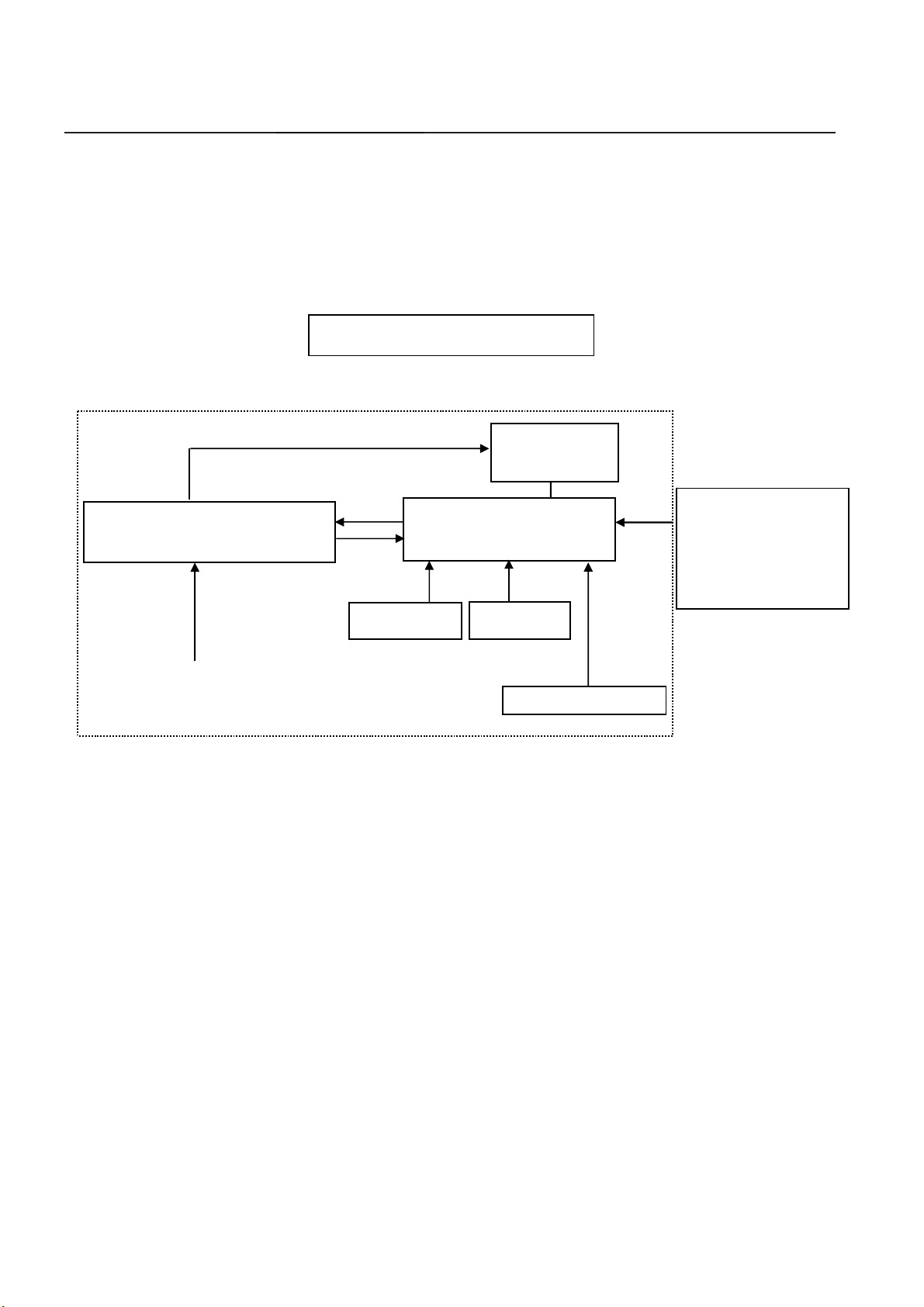
2. LCD Monitor Description
The LCD MONITOR will contain a main board, a power board, an audio board and a key board which house the flat
panel control logic, brightness control logic and DDC.
The power board will provide AC to DC Inverter voltage to drive the backlight of panel and the main board chips each
voltage.
Power board
(Include: adapter, inverter)
AC-IN
100V-240V
CCFL Drive.
Monitor Block Diagram
Flat Panel and
CCFL backlight
Main board
Audio board
Key board
HOST Computer
RS232 Connector
For white balance
adjustment in factory
mode
Video signal, DDC
4
Page 5
19" LCD Color Monitor AOC 912Sw
3. Operating Instructions
3.1 General Instructions
Press the power button to turn the monitor on or off. The control buttons are located in the front of the monitor.
By changing these settings, the picture can be adjusted to your personal preferences.
The power cord should be connected.
-
Connect the video cable from the monitor to the video card.
-
Press the power button to turn on the monitor, the power indicator will light up.
-
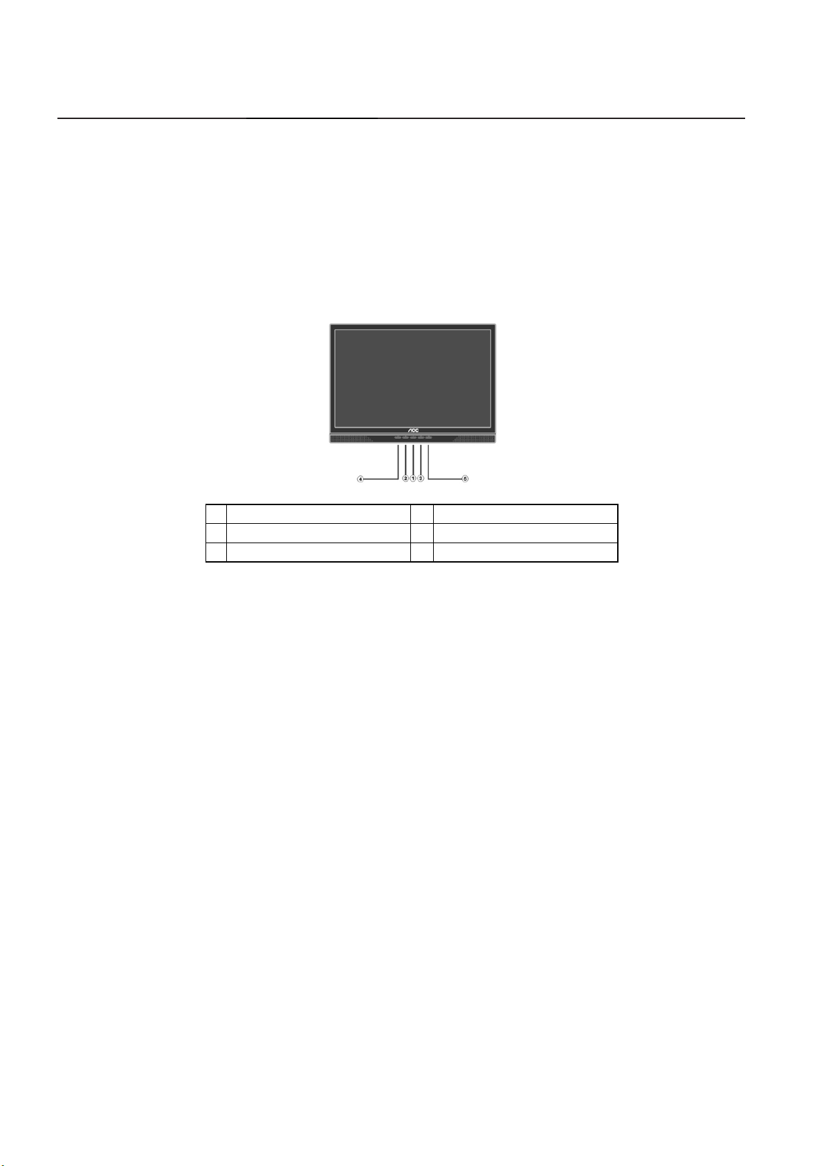
3.2 Control Buttons
1. Power Button & Indicator 2. < / Brightness
3. > / Contrast 4. Auto Config / Exit
5. Menu / Enter
• Power Button / Power Indicator: Press this button to turn the monitor ON or OFF.
Green — Power On mode. Orange — Off mode.
• MENU / ENTER : Activate OSD menu when OSD is OFF or activate/de-activate adjustment function when
OSD is ON or Exit OSD menu when in Volume Adjust OSD status.
• > / Contrast : This button will activate the Contrast control when the OSD is OFF or navigate through adjustment
icons when OSD is ON or adjust a function when function is activated.
• < / Brightness: This button will activate the Brightness control when the OSD is OFF or navigate through
adjustment icons when OSD is ON or adjust a function when function is activated.
• Auto Config / Exit:
1. When OSD menu is in active status, this button will act as EXIT-KEY (EXIT OSD menu).
2. When OSD menu is in off status, press this button for 2 seconds to activate the Auto Adjustment function.
The Auto Adjustment function is used to set the HPos, VPos, Clock and Focus.
NOTES:
• Do not install the monitor in a location near heat sources such as radiators or air dusts, or in a place subject to direct
sunlight, or excessive dust or mechanical vibration or shock.
• Save the original shipping box and packing materials, as they will come in handy if you ever have to ship your monitor.
• For maximum protection, repackage your monitor as it was originally packed at the factory.
• To keep the monitor looking new, periodically clean it with a soft cloth. Stubborn stains may be removed with a cloth
lightly dampened with a mild detergent solution. Never use strong solvents such as thinner, benzene, or abrasive
cleaners, since these will damage the cabinet. As a safety precaution, always unplug the monitor before cleaning it
5
Page 6
19" LCD Color Monitor AOC 912Sw
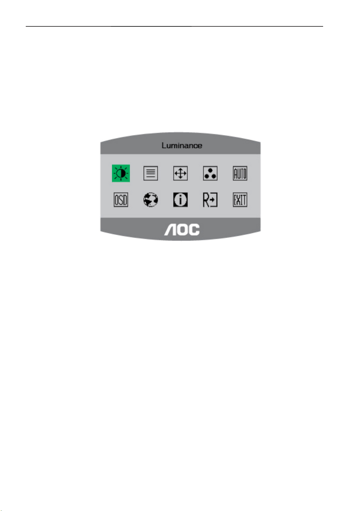
3.3 Adjusting the Picture
Adjustment steps:
1. Press the MENU-button to activate the OSD window.
2. Press < or > to select the desired function.
3. Press the MENU-button to select the function that you want to adjust.
4. Press < or > to change the settings of the current function.
5. To exit and save, select the exit function, or leave the monitor alone for 10 seconds. If you want to adjust any
other function, repeat steps 2-3.
6
Page 7
19" LCD Color Monitor AOC 912Sw
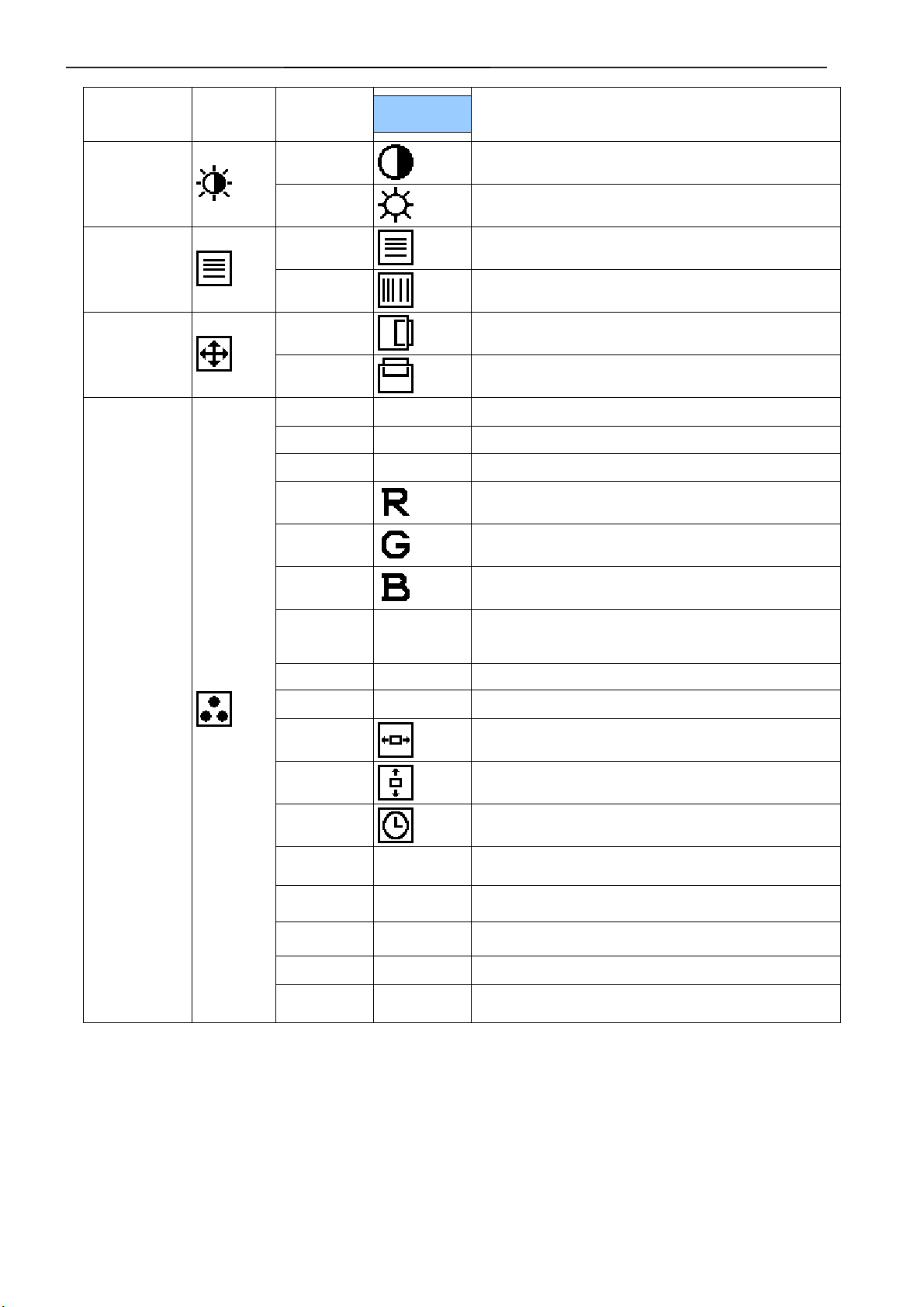
Main
Menu
Item
Main
Menu
Icon
Sub
Menu
Item
Sub Menu
Icon
Description
Luminance
Image Setup
Image Position
Contrast
Brightness
Focus
Clock
H. Position
V. Position
Warm N/A Recall Warm Color Temperature from EEPROM.
Cool N/A Recall Cool Color Temperature from EEPROM.
sRGB N/A Recall sRGB Color Temperature from EEPROM.
User / Red
User / Green
User / Blue
Sub
Menu
Item
Yes N/A Auto adjusting H/V position, focus, phase.
Sub Menu
Icon
Contrast from Digital-register.
Backlight Adjustment
Adjust Picture Phase to reduce Horizontal-Line noise
Adjust picture Clock to reduce Vertical-Line noise.
Adjust the horizontal position of the picture.
Adjust the vertical position of the picture.
Red Gain from Digital-register.
Green Gain Digital-register.
Blue Gain from Digital-register.
Description
Color Temp.
No N/A Back to main OSD.
H. Position
V. Position
OSD Timeout
Language N/A Set OSD language
Information N/A
Yes N/A Clear each old status of Auto-configuration.
No N/A Do not execute reset, return to main menu.
N/A N/A Exit OSD
Adjust the horizontal position of the OSD.
Adjust the vertical position of the OSD.
Adjust the OSD timeout.
Show the resolution, H/V frequency and input port of
current input timing.
7
Page 8
19" LCD Color Monitor AOC 912Sw
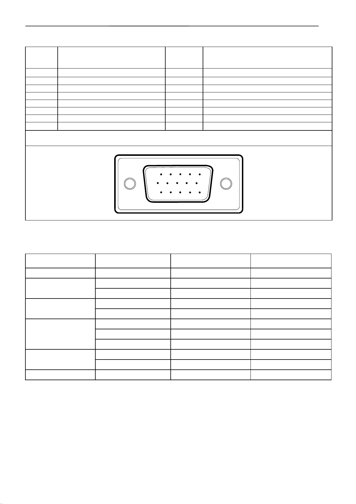
4. Input/Output Specification
4.1 Input Signal Connector
PIN NO.
1. Red 9. +5V
2. Green 10. Detect Cable
3. Blue 11. Ground
4. Ground 12. DDC-Serial Data
5. Ground 13. H-Sync
6. R-Ground 14. V-Sync
7. G-Ground 15. DDC-Serial Clock
8. B-Ground
DESCRIPTION
15 - Pin Color Display Signal Cable
PIN NO.
15
6
11 15
DESCRIPTION
10
4.2 Factory Preset Display Modes
STANDARD
Dos-mode
VGA
SVGA
XGA
SXGA
WXGA 1440 × 900 55.935kHz 59.8Hz
RESOLUTION
720 × 400 31.47kHz 70Hz
640 × 480 31.47kHz 60Hz
640 × 480 37.50kHz 75Hz
800 × 600 37.879kHz 60Hz
800 × 600 46.875kHz 75Hz
1024 × 768 48.363kHz 60Hz
1024 × 768 56.476kHz 70Hz
1024 × 768 60.021kHz 75Hz
1280 × 1024 64.00kHz 60Hz
1280 × 1024 80.00kHz 75Hz
HORIZONTAL
FREQUENCY
VERTICAL
FREQUENCY
8
Page 9
19" LCD Color Monitor AOC 912Sw
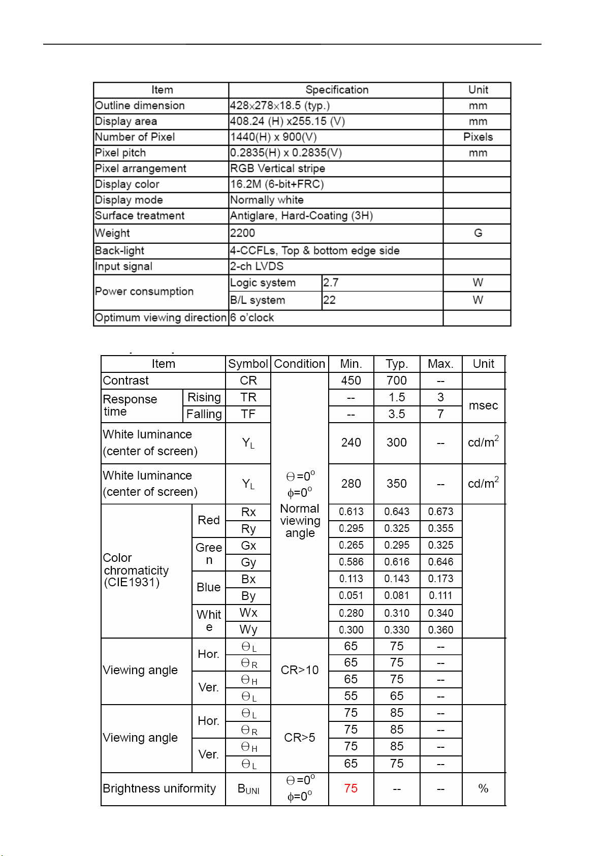
5 Panel Specification
5.1 Display Characteristics
5.2 Optical Characteristics
9
Page 10
19" LCD Color Monitor AOC 912Sw
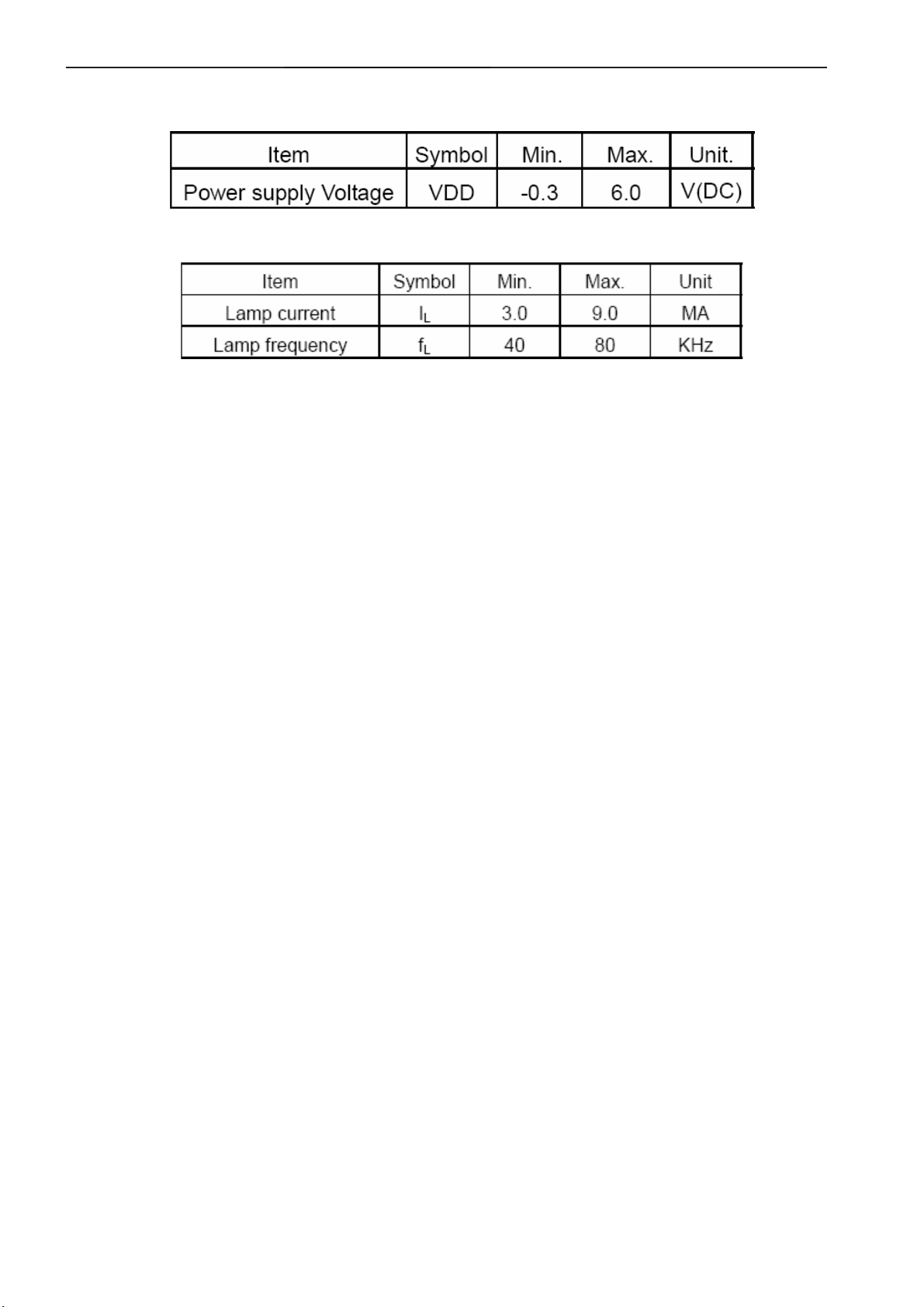
5.3 Parameter guide line for CCFL Inverter
TFT LCD Module:
Back Light Unit:
10
Page 11
19" LCD Color Monitor AOC 912Sw
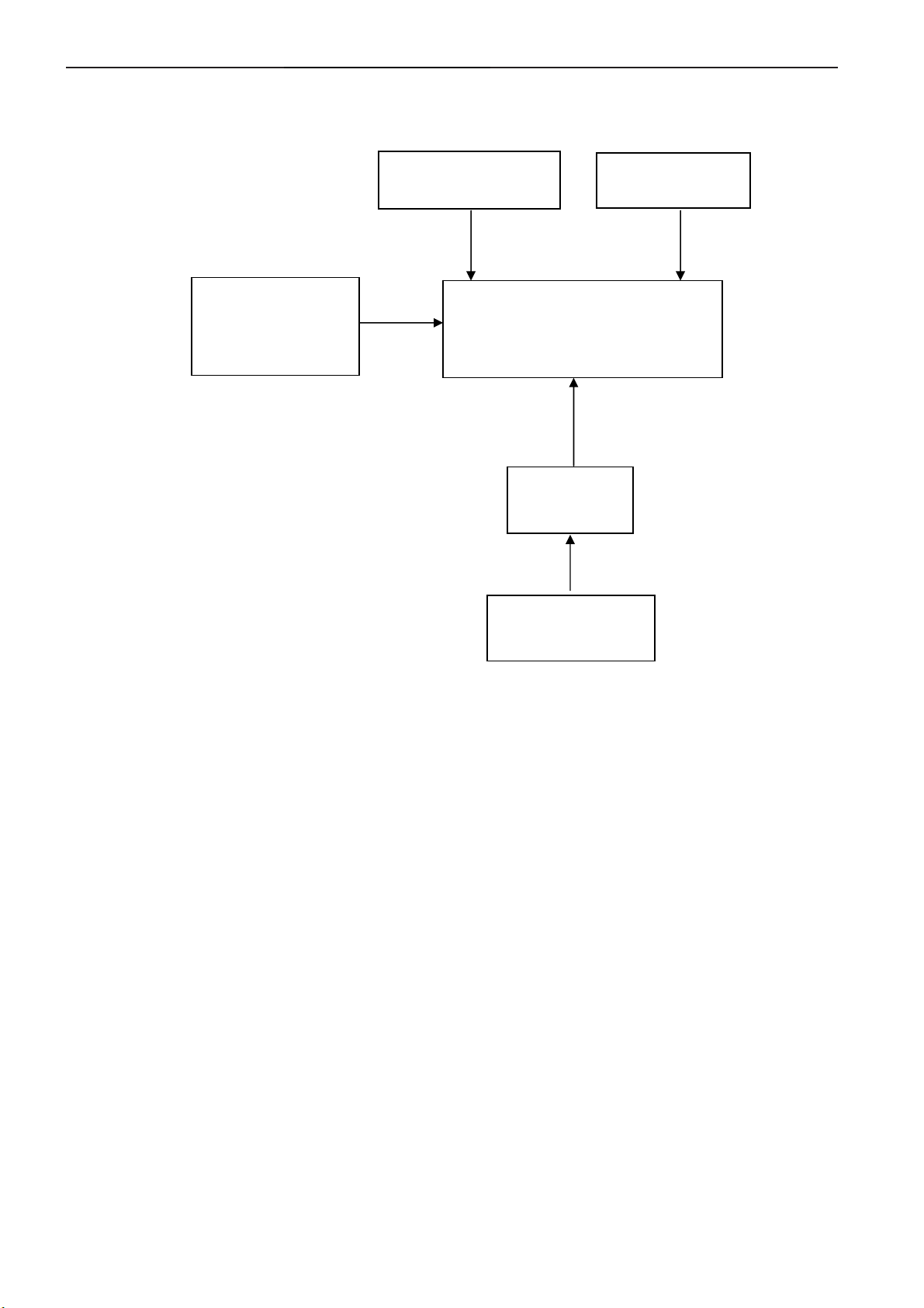
6. Block Diagram
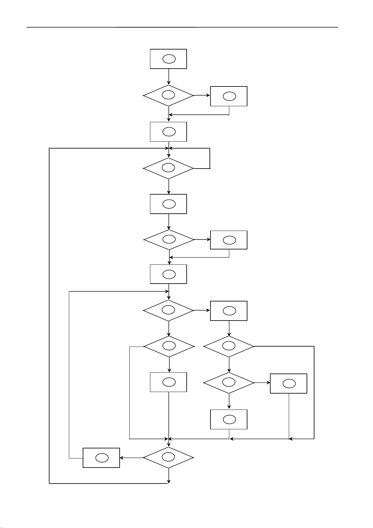
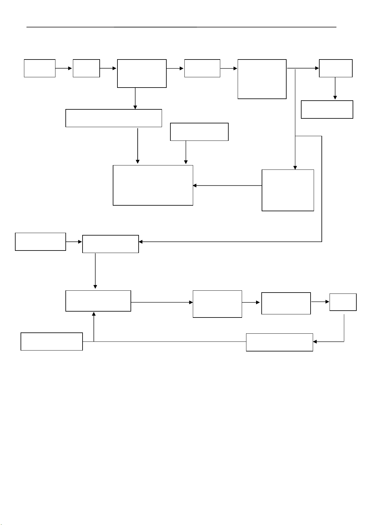
6.1 Software Flow Chat
1
2
N
4
5
Y
6
7
Y
N
N
3
18
9
10
Y
N
N
12
Y
14
19
N
11
13
15
17
N
Y
N
Y
16
Y
11
Page 12
19" LCD Color Monitor AOC 912Sw
1) MCU initialize.
2) Is the EPROM blank?
3) Program the EPROM by default values.
4) Get the PWM value of brightness from EPROM.
5) Is the power key pressed?
6) Clear all global flags.
7) Are the AUTO and SELECT keys pressed?
8) Enter factory mode.
9) Save the power key status into EPROM.
Turn on the LED and set it to green color.
Scalar initializes.
10) In standby mode?
11) Update the lifetime of back light.
12) Check the analog port, are there any signals coming?
13) Does the scalar send out an interrupt request?
14) Wake up the scalar.
15) Are there any signals coming from analog port?
16) Display "No connection Check Signal Cable" message. And go into standby mode after the message
disappear.
17) Program the scalar to be able to show the coming mode.
18) Process the OSD display.
19) Read the keyboard. Is the power key pressed?
12
Page 13
19" LCD Color Monitor AOC 912Sw
(
(
)
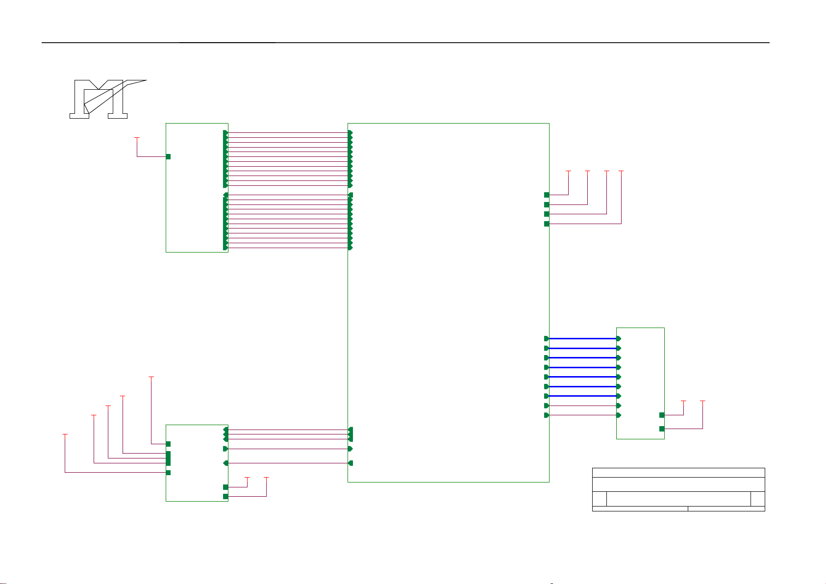
6.2 Electric Block Diagram
6.2.1 Main Board
Crystal (14.318MHz)
(X401)
EEPROM
M24C16
(U403)
Scalar TSUM16AWK
(Include MCU, ADC, OSD)
(U401)
D-Sub
Connector
(CN405)
H sync
V sync
RGB
LCD interface
CN101)
EEPROM
M24C02
U404
13
Page 14
19" LCD Color Monitor AOC 912Sw
6.2.2 Inverter / Power Board
AC inlet Filter
Rectifier and
filter
Start circuit R904, R931, R938
Switching circuit
PWM control
IC&MOSFET
On/off control
Start circuit
PWM control IC
Transform
er
OVP/OCP circuit
Push-pull
circuit
Rectifier and
filter D908,
D909
To main board
Feedback
circuit IC902,
IC903
LC resonant
12V/5V
12V
Lamp
Dimming control
Feedback circuit
14
Page 15
19" LCD Color Monitor AOC 912Sw
7. Schematic
7.1 Main Board
TSUM16AWK SCHEMATIC
VCC3.3
XGA/SXGA
B3
+5V
+5V
GNDR
GNDG
SOG
GNDB
HSYNC
VSYN C
DDCA_SDA
DDCA_SCL
DET_VGA
DDC_WP
CLK+
CLK-
DDCD_SDA
DDCD_SCL
DET_DVI
RIN
GIN
BIN
R+
R-
G+
GB+
B-
B4
RIN
GNDR
GIN
GNDG
SOG
BIN
GNDB
HSYNC
VSYN C
DDCA_SDA
DDCA_SCL
DET_VGA
DDC_WP
R+
RG+
GB+
BCLK+
CLKDDCD_SDA
DDCD_SCL
DET_DVI
LVDS OUTPUT
VCC3. 3
VCC1.8
VCC1.8
Vcc3. 3
+5V
+12V
+5V
+12V
3.INP UT
B5
PA[0.. 7]
PA[8.. 13]
PA[14..19]
+12V
+3V3
VCC1.8
+5V
B2
+12V
+3V3
VCC1.8
+5V
VCC3.3
on_BACKLIGHT
on_Panel
on_PANEL_12V
VCTRL
Adj_BACKLIGHT
VLCD
VLCD_12V
VLCD VLCD_12V
on_BACKLIGHT
on_Panel
on_PANEL_12V
VCTRL
Adj_BACKLIGHT
4.SCALER
PB[0.. 5]
PB[6.. 11]
PB[12..23]
GPO[0.. 4]
ESP
OSP
2.POW ER
PA[0.. 7]
PA[8.. 13]
PA[14.. 19]
PB[0.. 5]
PB[6.. 11]
PB[12.. 23]
GPO[0.. 4]
PA[0.. 7]
PA[8.. 13]
PA[14.. 19]
PB[0.. 5]
PB[6.. 11]
PB[12.. 23]
GPO[0.. 4]
ESP
OSP
VLCD_12V
VLCD
VLCD
VLCD_12V
5.PANEL INTERFACE
Tit le
Size Document Number Rev
B
Date: Sheet
715G1558-C-BJ.DSN
TOP
15Friday , July 21, 2006
A
of
15
Page 16

19" LCD Color Monitor AOC 912Sw
+12V
U701
+5V
C701
NC
L701
+12V
4
1 2
120 OHM
+5V3,4
+5V
L702
1 2
120 OHM
C709
0.1uF
adj_BACKLIGH T
C706
0.1uF
C707
+
100uF/25V
NC/ LT1117-18
3 2
VI VO
GND
GND
GND
GND
C710
+
100uF/25V
R706
4
R707
4.7K 1/16W
SOT-223
4
VO
GND
1
BL_ADJ(DC)
R31
0V ~ 3.3V
4.7K
0V ~ 5V
4.7K
R31
BL_ADJ
47
P W M
D C
4K7
CN701
1
3
5
7
9
11
CONN
+5V
NC
C32
N.C
1uF
2
4
6
8
10
12
R701
Q701
PMBS3904
+
C51
R32
0
1UF
X
1UF
BL_ON
BL_ADJ
GND
GND
1K 1/16W
R705
C703
NC
R29
X
1K
4.7K 1/16W
+
C708
C704
22uF/50V
R33
X
4.7K
1K 1/10W
1uF
R740
NC
+3V3
Q4
X
MMBT3904
R739
+
C723
22uF/50V
+3V3
+5V
R708
10K 1/16W
C711
0.1uF
Q703
PMBS3904
D704(SSM12L) Vf=0.38V and If=1A.
So when system power on, the
system loading is about 400mA
(3.3V is about 200mA and 1.8V is
about 200mA), So D35 changed
from 1N4148(or BAT42) to
SSM12L(schottky diode).
P.S: The 1N4148 Vf=0.7V~1V can't meet
LDO spec. The BAT42, Vf is OK but the
If=200mA(forward current) can not
meet current spec.
H1
9
9
123
123
R710 NC
R712 4.7K 1/16W
H2
678
5
678
5
4
4
TP
+5V
9
9
123
123
R711
10K 1/ 16W
678
678
5
4
TP
on_BACKLIGH T 4
H3
5
4
678
5
9
678
9
5
4
4
123
TP
123
D702
SMAL140
R704
100 1/16W
del
+5V
+5V3,4
D704
SMAL140
C713
0.1uF
U702
3
1
AIC1084-33PM
Q702
PZT2907A
TO-263
VIN
VOUT
ADJ
del
D701
SMAL140
Recommond to used "Blue" parts circuit
for VCC1.8V if you want to suppoert DDC
function when system power off
2
R702
51 1/16W
C702
+
22uF/50V
R703
2K 1/16W
VCTRL 4
VCC3. 3
C712
+
100uF/25V
VCC1.8
VCC1. 8 4
VCC3.3 4
VCC3. 3
VCC3.3 4
C714
0.1uF
For LVDS PANEL
R733
NC
on_PANEL
4
R734
10K 1/16W
R735
4.7K 1/16W
C721
0.1uF
R716
NC
+3V3
+5V
Q708
PMBS3904
R717
10K 1/16W
R723 51K 1/16W
C715
0.022uF
Q706
PMBS3906
0.1uF
C727
VLCD
Q704
AO3401L
+
22uF/50V
C717
C724
NC
1
VLCD_12V
32
Q705
NC
+
NC
C719
+5V
VLCD_12V 5
+12V
R730
NC
R728
NC
R731
NC
Tit le
Size D ocument Num ber Rev
Custom
Date: Sheet
Power
715G1558-C-BJ.DSN
35Friday , July 21, 2006
A
of
VLCD 5
+5V
+3V3
R722
R721
NC
0 1/16W
R727
NC
on_PANEL_12V
For RSDS and Panel VCC=12V
+5V
+12V
R720
R736
NC
NC
R737 NC/ 4K7
C722
NC
4
PMBS3904
Q709
+5V
+12V
R719
R729
NC
NC
R724 51K
C716
NC
Q707
NC
16
Page 17

19" LCD Color Monitor AOC 912Sw
CN406
RGB GND
HSYNC
VSYN C
SYNC GND
DDC SCL
DDC SDA
1/3shield
2/4shield
0/5shield
clk shield
DAT0+
DAT0-
DAT1+
DAT1-
DAT2+
DAT2-
DAT3+
DAT3-
DAT4+
DAT4-
DAT5+
DAT5-
JACK DVI
1716
11
12
13
14
15
HSI
VSI
D408
MLL5232B 5.6V
25
R
26
G
27
B
29
28
8
15
6
7
14
+5V
16
HPD
11
3
19
22
18
17
10
9
2
1
13
12
5
4
21
20
23
clk+
24
clk-
CN405
DB15
RED+
1
6
REDGREEN+
2
GREEN-
7
BLUE+
3
8
BLUE-
4
VGA5V
9
5
VGA_CON
10
MLL5232B 5.6V
SCL_DVI
SDA_DVI
DVI5V
HPD
DAT0+
DAT0DAT1+
DAT1DAT2+
DAT2-
DCLK+
DCLK-
R491
10K 1/ 16W
D406
FB409 430 OHM
D409
MLL5232B 5.6V
R472
NC
3
D417
BAV99
C447
1
2
0.1uF
2
3
D403
BAV99
C439 0.1uF
2
+5V
R471
10K 1/ 16W
R458 100 1/ 16W
D426
LL5232B 5.6V 5%
3
D418
BAV99
C448
1
0.1uF
PC5V
1
2
3
C440 0.1uF
2
3
D419
BAV99
C449
1
0.1uF
D404
BAV99
C441 0.1uF
1
2
R448
2.2K 1/16W
D414
LL5232B 5.6V 5%
3
D420
BAV99
C450
1
2
0.1uF
FB410 0 1/ 16W
FB411 0 1/ 16W
FB412 0 1/ 16W
3
D405
BAV99
1
DET_DVI 4
3
C451
2
0.1uF
R438
75 1/ 16W
ESD 5V
C442
22pF
R455 100 1/ 16W
R456 100 1/ 16W
D415
LL5232B 5.6V 5%
D421
BAV99
1
ESD5V
R446 1K 1/ 16W
R449
2.2K 1/16W
3
D422
BAV99
C452
1
2
0.1uF
D416
LL5232B 5.6V 5%
3
C453
2
0.1uF
R439
75 1/ 16W
R447 1K 1/ 16W
C443
22pF
D411
MLL5232B 5.6V
DVI5V
3
D423
BAV99
C454
2
1
0.1uF
R434 56 1/ 16W
R435 56 1/ 16W
R436 56 1/ 16W
R437 470 1/ 16W
R440
75 1/ 16W
R441 100 1/ 16W
R442 100 1/ 16W
R443 100 1/ 16W
+5V
R444
10K 1/ 16W
D410
MLL5232B 5.6V
D412
MLL5232B 5.6V
R457
10K 1/ 16W
C445
0.1uF
R462 10 1/ 16W
R463 10 1/ 16W
R464 10 1/ 16W
R465 10 1/ 16W
R466 10 1/ 16W
R467 10 1/ 16W
R468 10 1/ 16W
R469 10 1/ 16W
D424
BAV99
1
+5V 2,4
R445 100 1/ 16W
B+ 4
B- 4
G+ 4
G- 4
R+ 4
R- 4
CLK+ 4
CLK- 4
ESD 5V
C432 0.047uF
C433 0.047uF
C434 0.047uF
C435 0.047uF
C436 0.047uF
C437 0.047uF
C438 0.047uF
SCL_VGA
SDA_VGA
+5V
R470
D425
1 2
DDCA_SDA4
DDCA_SCL4
DDCD_SDA4
DDCD_SCL4
10K 1/10W
RLZ36B
RIN 4
GIN 4
BIN 4
SOG 4
GNDR 4
GNDG 4
GNDB 4
DET_VGA 4
HSYNC 4
VSYN C 4
R450
10K 1/ 16W
R453 100 1/ 16W
R454 100 1/ 16W
R459
10K 1/ 16W
+5V
PC5V
1
2
D407
BAV70
R451
10K 1/ 16W
R460
10K 1/ 16W
3
R452
10K
+5V
R461
10K
Tit le
Size Docum ent Num ber Rev
B
Date: Sheet
U404
8
7
6
DVI5V
1
2
3
R473
NC
VCC
WP
SCL
M24C02
D413
BAV70
U405
8
7
6
M24C02
VCC
WP
SCL
A0
A1
A2
GNDSDA
A0
A1
A2
GNDSDA
C444
1
0.22uF
2
3
45
DDC_WP 4
C446
1
0.22uF
2
3
45
DDC_WP 4
Input
715G1558-C-BJ.DSN
of
45Friday , July 21, 2006
A
17
Page 18

19" LCD Color Monitor AOC 912Sw
VCC3.3
R403 390 1%
C401
2
SDO
1
CE#
6
SCK
R492
20
R493
20
R415
59
58
56
55
57
54
53
63
64
65
66
39
40
42
43
45
46
48
49
36
37
51
62
0.1uF
61
70
71
72
73
19
32
33
102
104
R416
10K 1/16W
+5V
R430
1K 1/16W
Q404
PMBS3904
DDCA_SDA3
DDCA_SCL3
+5V
+
C418
10uF/50V
R404
10K 1/16W NC
+5V
Reset
Circuit
C417
0.22uF
10K 1/16W
U406
R489
10K 1/16W
VCC3.3
R486
NC
R487
10K 1/16W
23
RSTVCC
GND
ASM810MEURF-T
1
R490
GNDR3
GNDG3
GNDB3
HSYNC3
VSYNC3
DDCD_SDA3
DDCD_SCL3
AVDD
U402
8
VDD
7
HOLD#
3
WP#
4 5
VSS SD I
WP
C421 22pF
X401
14.318MHz
C423 22pF
VCC3.3
R407 NC
R410 NC
RIN3
GIN3
SOG3
BIN3
R+3
R-3
G+3
G-3
B+3
B-3
CLK+3
CLK-3
SST25VF010-20-4C-SAE
10K 1/16W
R431 NC
R433 4.7K 1/16W
VDVI
VMPLL
44
50
AVDD_DVI
AVDD_DVI
RIN0P
RIN0M
GIN0P
GIN0M
SOGIN0
BIN0P
BIN0M
HSYNC0
VSYNC0
DDCA_SDA
DDCA_SCL
R+
RG+
GB+
BCK+
CKDDCD_SDA
DDCD_SCL
REXT
REFP
REFM
SDO
CSZ
SCK
SDI
RST
XIN
XOU T
MODE [0]
MODE [1]
R432 10K 1/16W
VPLL
AVDD
52344
60
BYPASS
AVDD_PLL
AVDD_ADC
AVDD_MPLL
RSDS/LVDS/TTL
GND
GND
GND
GND
41
47
3896116
13
C431
1uF/25V
VDDP
67
14
95
103
VDDP
VDDP
VDDP
VDDP
GND
GND
OUT-L+
OUT-L-Volume
VDDC
12
68
97
115
117
VDDP
VDDC
VDDC
VDDC
VDDC
NC/LVACKP/NC
NC/LVACKM/NC
RA1P/LVA2P/RA2
RA1N/ LVA2M/RA3
RA2P/LVA1P/RA4
RA2N/ LVA1M/RA5
RA3P/LVA0P/RA6
RA3N/ LVA0M/RA7
GA3P/LVA3P/GA6
GA3N/LV A3M/GA7
RB1P/NC/RB2
RB1N/NC/RB3
RB2P/NC/RB4
RB2N/NC/RB5
RB3P/NC/RB6
RB3N/NC/RB7
GB1P/NC/GB2
GB1N/NC/ GB3
GB2P/NC/GB4
GB2N/NC/ GB5
GB3P/NC/GB6
GB3N/NC/ GB7
CLKAP/LVB3P/ LHSYN C
CLKAN/LVB3M/LVSYNC
CLKBP/LVBC KP/LCK_ODD
CLKBN/L VBCKM/LDE
NC/LVB2 P/NC
NC/LVB2M/NC
BB1P/LVB1P/BB2
BB1N/LVB1M/BB3
BB2P/LVB0P/BB4
BB2N/LVB0M/BB5
BB3P/NC/BB6
BB3N/NC/BB7
GPIO_P16/PWM2
GPIO_P15/PWM0
PWM2/GPIO_P24
GPIO_P27/PWM1
PWM1/GPIO_P25
GPIO_P00/SAR1
GPIO_P01/SAR2
GPIO_P02/SAR3
PWM0/GPIO_P26
GPIO_P10/I2C_MCL
GPIO_P11/I2C_MDA
FB407
600 OHM
FB408
600 OHM
CN404
1
3
5
7
9
11
13
CONN
VCTRL
GPIO_P22
GPIO_P23
GPIO_P03
GPIO_P12
RSTN
GPIO_P06
GPIO_P07
GPIO_P13
GPIO_P14
2
4
6
8
10
12
14
NC
NC
NC
NC
NC
NC
NC
NC
NC
NC
NC
NC
NC
NC
NC
NC
NC
NC
NC
11
107
PA0
108
PA1
109
PA2
110
PA3
PA4
111
PA5
112
PA6
113
PA7
114
PA8
98
99
PA9
100
PA10
PA11
101
105
PA12
106
PA13
89
PA14
PA15
90
PA16
91
92
PA17
PA18
93
94
PA19
9
PB0
10
PB1
15
PB2
PB3
16
17
PB4
PB5
18
2
PB6
3
PB7
5
PB8
PB9
6
7
PB10
8
PB11
118
PB12
PB13
119
120
PB14
121
PB15
122
PB16
PB17
123
124
PB18
PB19
125
PB20
126
127
PB21
128
PB22
PB23
1
80
81
88
87
86
85
84
83
82
75
74
26
35
69
78
79
20
21
22
23
24
25
27
28
29
30
31
77
76
+12V
+5V
10K 1/16W
OUT-R+
OUT-R-
ESP
OSP
GPO0
GPO1
GPO2
GPO3
GPO4
R488 100R 1/10W
R418 100 1/16W
R420 100 1/16W
R411 100 1/16W
R422 4.7K 1/16W
R423 4.7K 1/16W
VCC3.3
R424
R425
10K 1/16W
10K 1/16W
R428 100 1/16W
R429 100 1/16W
+12V 2
+5V 2,3
+5V
R484
R485
10K 1/16W
AUDIO_STBY
AUDIO_MUTE
VCTRL 2
P[0..7]
PA[8..13]
PA[14..19]
PB[0..5]
PB[6..11]
PB[12..23]
GPO[0..4]
WP
KEY1
KEY2
POWER
Volume
AUDIO_MUTE
AUDIO_STBY
R426
10K 1/16W
R427 100 1/16W
Option
PA[0..7] 5
PA[8..13] 5
PA[14..19] 5
PB[0..5] 5
PB[6..11] 5
PB[12..23] 5
ESP 5
OSP 5
GPO[0..4] 5
R405
22K 1/16W
10K 1/16W
on_PANEL_12V 2
DET_DVI 3
DET_VGA 3
on_PANEL 2
on_BACKLIGHT 2
adj_BACKLI GHT 2
U403
8
VCC
7
WP
6
SCL
AT24C16N-10SC-2.7
KEY_B
LED_G
KEY_AUTO
KEY_RI GHT
POWER
OUT-L+
OUT-L-
VDDC
FB401
VCC1.8
VCC1.82
VCC3.32
DDC_WP 3
Q402
PMBS3904
C422
0.1uF
R406
C425
0.22uF
1
A0
2
A1
3
A2
45
GNDSDA
CN403
1
3
5
7
9
11
13
15
CONN
VCC3.3
R481
R482
NC
NC
Q405
NC
KEY_A
2
LED_A
4
6
KEY_MENU
KEY_LEFT
8
10
12
KEY_C
OUT-R+
14
16
OUT-R-
R483
KEY2
KEY1
LED_G
LED_A
POWER
KEY A
NC
C616
NC
C426
0.1uF
C429
C427
C428
0.1uF
0.1uF
0.1uF
+5V
R412
10K 1/16W
R417 20K 1/16W
C424 0.1uF
3.9K 1/16W
C430
D401
0.1uF
RLZ36B
1 2
VCC3.3
VCC3.32
VCC3.32
+5V 2,3
10K 1/16W
600 OHM
600 OHM
R474
22uF/50V
FB403
R413
VCC3.3
D402
1 2
C403
RLZ36B
+
C404
0.1uF
C408
22uF/50V
VCC3.3
VCC3.3
+5V
R475
3.9K 1/16W
C405
0.1uF
VDDP
+
FB404
600 OHM
FB406
600 OHM
R414
240 1/16W
Q401
PMBS3906
R421 0 1/16W
C406
0.1uF
C409
C411
C410
0.1uF
0.1uF
0.1uF
VDVI
C415
C414
0.1uF
0.1uF
VMPLL
C419
C420
0.1uF
0.1uF
10K 1/16W
LED_G
R476 1K 1/16W
R477 1K 1/16W
Title
Size D ocument Number Rev
C
Date: Sheet
VCC3.32
C412
0.1uF
R408
C413
0.1uF
VCC3.32
R478 1K 1/16W
R479 1K 1/16W
VCC3.3
+5V
R409
75 1/16W
Q403
PMBS3906
R480 1.5K 1/16W
Scaler
715G1558-C-BJ.DSN
FB402
600 OHM
VCC3.3
R419 0 1/16W
AVDD
FB405
600 OHM
LED_A
KEY_AUTO
KEY_RI GHT
KEY_MENU
KEY_LEFT
C407
0.1uF
VPLL
C416
0.1uF
KEY_A
KEY_B
KEY_C
A
25Friday, July 21, 2006
of
18
Page 19

19" LCD Color Monitor AOC 912Sw
VLCD
R89
PB[0. .5]
PB0
RB1P
RB1N
PB1
RB2P
PB2
PB3
RB2N
PB4
RB3P
PB5
RB3N
PB[6.. 11]
PB6
GB1P
GB1N
PB7
PB8
GB2P
PB9
GB2N
PB10
GB3P
GB3N
PB11
PB[12.. 23]
CLKBP
PB14
CLKBN
PB15
PB18
BB1P
BB1N
PB19
BB2P
PB20
PB21
BB2N
BB3P
PB22
PB23
BB3N
R101 NC/0
OSP
ESP
R102 NC/0
C106
NC
R91
Table 1
X
X
X
V
V
V
Table 1
AU 17
QDI 17
CPT 17
INNOLUX 15
HannStar 15
CPT 15
LG 15
Innolux 17"
R90
3.3V
3.3V
3.3V
3.3V
NC
0R
0R
0R
0R
NC
C107
NC
R103 NC
R104 NC
R105 NC
R106 NC
R107 NC
R108 NC
R109 NC
R92
NC
12V
0R
NC
NC
NC
NC
RA3N
RA3P
RA2N
RA2P
RA1N
RA1P
GA3N
GA3P
GA2N
GA2P
GA1N
GA1P
CLKAN
CLKAP
BA3N
BA3P
BA2P
BA1N
BA1P
GPOO1
GPOO0
GPOO3
GPOO2
GPOO4
R93
3.3V
3.3V
3.3V
3.3V
FB0N
FB0P
FB1N
FB1P
FB2N
FB2P
FG0N
FG0P
FG1N
FG1P
FG2N
FG2P
FCLKN
FCLKP
FR0N
FR0P
FR1N
FR1P
FR2N
FR2P
STH
LP
POL
STV2
CLKV
STV1
OE
R94
5V
0R
NC
0R
0R
0R
3.3V
0R
R95
5V
0R
NC
NC
NC
NC
0R
CN102
1
2
3
4
5
6
7
8
9
10
11
12
13
14
15
16
17
18
19
20
21
22
23
24
25
26
27
28
29
30
31
32
33
34
35
36
37
38
39
40
41
42
43
44
45
46
47
48
49
50
IL-FHR -B50S-HF (JAE)
R97
R96
5V
NC
0R
12V
0R
NC
NC
NC
12V
0R
NC
NC
NC
3.3V
0R
NC
CN103
RXO0RXO1RXO2RXOCRXO3RXE0RXE1RXE2RXECRXE3-
R738
VLCD
1
2
3
4
5
6
7
8
9
10
11
12
13
14
15
16
17
18
19
20
21
22
23
24
25
26
27
28
29
30
IL-FH R-B30S-HF (JAE)
CN101
2
1
4
3
6
5
8
7
10
9
CONN
L703
BEAD 120OHM
1 2
R741
150R 1/4W
12
14
16
18
20
22
24
26
28
30
VLCD 2
C726
0.1uF/ 16V
11
13
15
17
19
21
23
25
27
29
RXO0+
RXO1+
RXO2+
RXOC+
RXO3+
RXE0+
RXE1+
RXE2+
RXEC+
RXE3+
LVB0P
LVB1P
LVB2P
LVBCKP
LVB3P
LVA0P
LVA1P
LVA2P
LVACKP
LVA3PC101
RB3N
B0N
B0P
RB3P
B1N
RB2N
B1P
RB2P
RB1N
B2N
B2P
RB1P
BG0N
GB3N
GB3P
BG0P
BG1N
GB2N
GB2P
BG1P
GB1N
BG2N
BG2P
GB1P
BCLKN
CLKBN
BCLKP
CLKBP
BR0N
BB3N
BR0P
BB3P
BB2N
BR1NBA2N
BB2N
BR1P
BB2P
BR2N
BB1N
BR2P
BB1P
LVB0M
LVB1M
LVB2MGPOO3
LVBCKM
LVB3M
LVA0M
LVA1M
LVA2M
LVACKM
LVA3M
NC
12V
0R
NC
NC
NC
NC
C725
22uF/50V
+
150R 1/4W
CN8
PB[0..5]4
PB[6.. 11]4
PB[12.. 23]4
OSP4
ESP4
VLCD2
VLCD_12V
VLCD_12V2
R88
RP1
CN9
X
X
X
V
V
V
X
V
PA[0..7]
PA0
LVACKP
PA1
LVACKM
PA2
LVA2P
PA3
LVA2M
PA4
LVA1P
PA5
LVA1M
PA6
LVA0P
PA7
LVA0M
PA12
LVA3P
LVA3M
PA13
PB[12.. 23]
PB12
LVB3P
PB13
LVB3M
PB14
LVBCKP
PB15
LVBCKM
LVB2P
PB16
PB17
LVB2M
LVB1P
PB18
LVB1M
PB19
LVB0P
PB20
PB21
LVB0M
C104
NC
LVDS Panel
RSDS Panel
C105
NC
GPOO0
GPOO1
GPOO2
GPOO4
CN7
X
V
8
7
6
C103
C102
NC
NC
NC
PA2
PA3
PA4
PA5
PA6
PA7
PA8
PA9
PA10
PA11
PA12
PA13
PA14
PA15
PA16
PA17
PA18
PA19
PB12
PB13
GPO0
GPO1
GPO2
GPO3
GPO4
PA[0. .7]4
RA1P
RA1N
RA2P
RA2N
RA3P
RA3N
GA1P
GA1N
GA2P
GA2N
GA3P
GA3N
PB[12..23]4
BA1P
BA1N
BA2P
BA2N
BA3P
BA3N
CLKAP
CLKAN
RP101 NC
1
2
3
4 5
R110 NC
PA[0..7]4
PA[8..13]4
PA[14.. 19]4
GPO[0.. 4]4
PA[0..7]
PA[8..13]
GPO[0.. 4]
19
Tit le
Size Document Number R ev
B
Date: Sheet
PANEL INTERFACE
715G1558-C-BJ.DSN
of
55Friday , July 21, 2006
A
Page 20

19" LCD Color Monitor AOC 912Sw
7.2 Power Board
D909
SP20100
2
C932
C933
R920
1K 0805
C918
0.1uF
R921
1K 080 5
R934
47 1206
R935
47 1206
C934
JUMP
C936
470uF/25V
C935
470uF/25V
R937
100 1206
R936
100 1206
R916
100 1206
Over voltage protection
ZD901
RLZ13B
1 2
R926
2K 0805
C931
1000PF/500V
+
+
1 2
+
ZD902
RLZ5.6B
+
C912
470uF/25V
C904
470uF/25V
R927
10KΩ 1/4W
R925
3.6K 0805 1%
C919
0.1uF
R922
1K 080 5
L903
L904
3.5UH
470UF/ 25V
3.5UH
+
C937
+
C911
470UF/ 25V
R923
33K 0805 1%
R924
2.4K 0805 1%
1 2
ZD903
PTZ9.1B
F902
FUSE
ON/OF F
DIM
C916
0.1uF
F903
FUSE
12
11
10
9
8
7
6
5
4
3
2
1
C917
0.1uF
+12V
+5V
CN902
1
-+
2
3
2
3
1
4
VAR901
NC
2
3
1
4
C903
0.47uF/ 275V
R902
R901
680KΩ 1/4W
680KΩ 1/4W
3
BD901
4A 800V
4
L902
73L 174-65-LS
L901
2.0MH
R903
680KΩ 1/4W
NR901
NTCR
12
C905
100uF/450V
C901
1000PF/250V
C902
1000PF/250V
12
t
F901
FUSE
!
+
1 2
Over voltage protection
ZD906
NC
R941
NC
C913
NC
C908
0.1uF
IC901
LD7575
R913
100K 0805
LD7575
7
N.C
RT1CS
R931
100KΩ 1/4W
R904
100KΩ 1/4W
R938
100KΩ 1/4W
8
HV
OUT
GND
4
2
ZD907
COMP
6
VCC
NC
R939
NC
NC
IC904
1 2
5
3
ZD905
NC
TO PI N3
22Ω 1/4W
TO PI N3
1 2
R910
RLZ18B
D904
ZD904
C909
220pF
+
C907
NC
1N4148W
1 2
R911
1KΩ 1/4W
C910
470pF/50V
0.0015uF/2KV
D903
0Ω 1/4W
C930
R912
10K 0805
R905
100K 2W
D901
FR107
D902
FR103
+
C906
22UF/ 50V
Q903
STP10NK70ZFP
12
FB901
BEAD
Over current protection
R914
0.47 2W
R909
5.1Ω 1/4W
47 1206
!
80GL17T 37 L GP
T901
6
4
2
1
C900
0.0022UF
R919
470Ω 1/4W
12
IC902
R906
3
1
95
10
7
8
11
12
43
IC903
KIA431A-AT/P
D908
SP20150
2
3
0.0015uF/2KV
1
0.0015uF/2KV
ON/OFF
DIM
NC
GND
GND
GND
GND
GND
+5V
+5V
+12V
+12V
CN901
SOCKET
20
AOC (Top Victory) Electronics Co., Ltd.
Tit le
Size Document Number Rev
Date: Sheet
1.POWER OUTPUT 12V & 5 V
G1899-1-HP-X-1-060720
Friday , July 21, 2006
11
of
1
Page 21

19" LCD Color Monitor AOC 912Sw
PT801
!
80GL19T 8 DN GP
+12V
ON/OFF
DIM
PID
R803
10K 0805
R808
200K 0805
R801
NC
C803
0.01uF
C801
0.1uF
R811
R806
10K 0805
47K 0805
C804
1uF/25V
10K 0805
R802
300KΩ 1/8W
Q801
PMBS3904
C840
1uF/25 V
R809
180KΩ 1/8W
R812
C814
0.22uF/25V
R804
10K 0805
Q802
PMBS3904
VCC
C805
1000pF
1 2
ZD801
RLZ5.6B
R813
1MΩ 1/8W
R805
470Ω 1/4W
Q803
PMBS3904
R810
1MΩ 1/8W
R814
750KΩ 1/8W
+
C811
470UF/25V
R807
22Ω 1/4W
C806
1uF/25V
C828
0.1uF
5.1Ω 1/4W
R842
?
Q806
AM9945
R828
IC801
1
DRV1
2
VDDA
3
TIME R
4
DIM
5
ISEN
6
VSEN
7
OVPT
NC18NC2
OZ9938
332/1206
C822
30 1206
R861
30 1206
30 1206
8
S1N1G1N2S2N3G2N
PGND
DRV2
GNDA
CT
SSTCMP
LCT
ENA
5
3
4
1 8
332/1206
C823
R862
R829
30 1206
?
D2N5D2N6D1N7D1N
4
R815
5.1Ω 1/4W
R837
16
15
14
13
12
11
10
9
100K 1/8W
C807
0.01uF
1
2
R816
1MΩ 1/8W
C808
0.0068uF
D801
BAV99
C809
0.047uF
7
D806
3
1
2
C820
470pF/50V
BAV99
R817
33KΩ 1/8W
C810
560PF/5 0V
C816
22pF/3KV
C841
22pF/3KV
C825
5pF/3KV
C824
5pF/3KV
C818
0.0033uF/16V
3
82KΩ 1/8W
R825
51KΩ 1/8W
R823
Q804
RK7002
C819
0.047uF
D809
1N4148W
R822
6.2MΩ 1/2W
R827
7.5K / 0805
R826
R841
430 0805 1%
R860
1MΩ 1/8W
open lamp protection
C844
0.1uF
430 0805 1%
Q807
RK7002
1MΩ 1/8W
Q808
RK7002
1MΩ 1/8W
Q809
RK7002
1MΩ 1/8W
Q810
RK7002
1MΩ 1/8W
D802
R846
R847
R848
R849
OPT1
R836
1K 1/10W
OPT2
1
2
BAV99
3
R858
750Ω 1/8W
C838
0.1uF
C839
0.1uF
C842
0.1uF
C843
0.1uF
R853
R852
R850
R851
CONN
4.7KΩ 1/8W
4.7KΩ 1/8W
4.7KΩ 1/8W
4.7KΩ 1/4W
CN801
CONN
1342
CN802
D810
1N4148W
D811
1N4148W
D812
1N4148W
D813
1N4148W
1342
OPT1
OPT2
OPT3
OPT4
AOC (Top Victory) Electronics Co., Ltd.
Titl e
HP W19 series 17" 19'' 4 LAMPS INVERTER
Size Document Number Rev
G1899-1-HP-X-1-060720
Date: Sheet
Tuesday, February 27, 2007
11
of
!
C829
0.1uF
1
+
C815
470UF/ 25V
R863
?
Q805
AM9945
30 1206
332/1206
C813
R818
30 1206
8
S1N1G1N2S2N3G2N
C812
R819
30 1206
D2N5D2N6D1N7D1N
4
332/1206
R864
30 1206
?
21
PT802
80GL19T 8 DN GP
5
3
4
1 8
D803
1
2
BAV99
7
3
C831
470pF/50V
C834
22pF/3KV
C837
22pF/3KV
C826
5pF/3KV
C835
5pF/3KV
C827
0.0033uF/16V
1
2
82KΩ 1/8W
D805
R830
BAV99
3
R832
6.2MΩ 1/2W
R831
7.5K 0805
CN803
1342
OPT3
OPT4
D804
BAV99
1
2
3
R824
750Ω 1/8W
R843
1K 0805
CONN
CONN
CN804
1342
Page 22

19" LCD Color Monitor AOC 912Sw
8. PCB Layout
8.1 Main Board
22
Page 23

19" LCD Color Monitor AOC 912Sw
23
Page 24

19" LCD Color Monitor AOC 912Sw
24
Page 25

19" LCD Color Monitor AOC 912Sw
8.2 Power Board
25
Page 26

19" LCD Color Monitor AOC 912Sw
26
Page 27

19" LCD Color Monitor AOC 912Sw
8.3 Key Board
27
Page 28

19" LCD Color Monitor AOC 912Sw
9. Maintainability
9.1 Equipments and Tools Requirement
1. Voltmeter.
2. Oscilloscope.
3. Pattern Generator.
4. DDC Tool with an IBM Compatible Computer.
5. Alignment Tool.
6. LCD Color Analyzer.
7. Service Manual.
8. User Manual.
28
Page 29

19" LCD Color Monitor AOC 912Sw
9.2 Trouble Shooting
9.2.1 Main Board
No Power
Please reinsert and make sure
the AC of 100-240 is normal
Measure U702 Vout=3.3V
Q702 Vc=1.8V
No power
Press power key and look
if the picture is normal
NG
OK
OK
X401 oscillate waveforms
are normal
OK
NG
NG
NG
Reinsert or check the
Adapter/Inverter
section
Check CN701 or replace
U702, Q702
Replace X401
Replace U401
29
Page 30

19" LCD Color Monitor AOC 912Sw
No Picture (LED orange)
Measure U702 Vout=3.3V
Q702 Vc=1.8V
No picture
The button if under
control
OK
OK
X401 oscillate
waveform is normal
OK
Check HS/VS from
CN405 is normal
OK
Replace U401
NG
NG
NG
X401 oscillate
waveform is normal
OK
Check reset circuit of
U401 is normal
Replace U401
NG
Replace U702, Q702
Replace X401
Check Correspondent
component
OK
NG
Replace X401
NG
Check Correspondent
component
30
Page 31

19" LCD Color Monitor AOC 912Sw
White Screen
Measure C725 (+) =5V
Check CN101 connector or
solder normal?
Replace CN101 or
re-solder
White screen
OK
NG
OK
Replace PANEL
NG
Checks Q704, Q706,
are broken
NG
OK
Check X401
OK
Replace U401
Replace Q704,
Q706
NG
Replace X401
31
Page 32

19" LCD Color Monitor AOC 912Sw
9.2.2 Power Board
1. No Power
No power
Check to CN902 Pin1, 2 =12V and Pin3, 4 = 5 V
OK
NG
Check Interface board
Check AC line volt 120V or 220V
OK
NG
Change F901, Check BD901, Q903, IC901
Check the voltage of C905 (+)
OK
NG
Check bridge retified circuit
Check start voltage for the Pin6 of IC901
NG
OK
Change IC901
Check the auxiliary voltage is smaller than 20V
NG
OK
Check IC902,IC903
Check Q903…OLP circuit
Check D908, D909, ZD903…
32
Page 33

19" LCD Color Monitor AOC 912Sw
2. W/LED No Backlight
Check C811 (+) =12V
OK
NG
Check adapter circuit
Check ON/OFF signal
OK NG
Check Interface board
Check IC801 PIN2=5V
Check the Pin1, Pin15 of IC801 have square wave
NGOK
Check Q801,Q802,Q803
OK
NG
Check IC801
Check Q805,Q806 have the output of
square wave at short time.
OK
NG
Check Q805,Q806,PT801,PT802
Check the resonant wave of Pin7 & Pin8 for PT801/PT802
OK
NG
Check C816, C841 or C834, C837
Check the output of PT801/PT802
Change PT801 or PT802
Check connecter & lamp
33
Page 34

19" LCD Color Monitor AOC 912Sw
9.2.3 Key Board
OSD is unstable or not working
Is Keypad board connecting normally?
NG
Connect Keypad Board
Is Button Switch normally?
OK
NG
Replace Button Switch
Is Keypad board normally?
OK
NG
Replace Keypad Board
OK
Check main board
34
Page 35

19" LCD Color Monitor AOC 912Sw
10. White- Balance, Luminance Adjustment
Approximately 30 minutes should be allowed for warm up before proceeding White-Balance adjustment.
1. How to do the Chroma-7120 MEM. Channel setting
A. Reference to chroma 7120 user guide
B. Use “ SC” key and “ NEXT” key to modify x, y, Y value and use “ID” key to modify the
TEXT description Following is the procedure to do white-balance adjust
2. Setting the color temp. you want
A. MEM.CHANNEL 3 (7800 color):
7800 color temp. parameter is x = 296 ±20, y = 311 ±20, Y = 180 cd/m
B. MEM.CHANNEL 4 (6500 color):
6500 color temp. parameter is x = 313±20, y = 329 ±20, Y =180 cd/m2
3. Into factory mode of 912Sw
Turn on power, press the MENU button, pull out the power cord, and then plug the power cord. Then the factory
OSD will be at the left top of the panel.
4. Bias adjustment:
2 ,
Set the Contrast
to 50; Adjust the Brightness to 90.
5. Gain adjustment:
Move cursor to “-F-” and press MENU key
A. Adjust C2 (7800) color-temperature
1. Switch the Chroma-7120 to RGB-Mode (with press “MODE” button)
2. Switch the MEM. Channel to Channel 3 (with up or down arrow on chroma 7120)
2
3. The LCD-indicator on chroma 7120 will show x = 296 ±20, y = 311 ±20, Y =180 cd/m
4. Adjust the RED of color1 on factory window until chroma 7120 indicator reached the value R=100
5. Adjust the GREEN of color1 on factory window until chroma 7120 indicator reached the value G=100
6. Adjust the BLUE of color1 on factory window until chroma 7120 indicator reached the value B=100
7. Repeat above procedure (item 4,5,6) until chroma 7120 RGB value meet the tolerance =100±5
B. Adjust C1 (6500) color-temperature
1. Switch the chroma-7120 to RGB-Mode (with press “MODE” button)
2. Switch the MEM .channel to Channel 4(with up or down arrow on chroma 7120)
2
3. The LCD-indicator on chroma 7120 will show x = 313 ±20, y = 329 ±20, Y = 180 cd/m
4. Adjust the RED of color3 on factory window until chroma 7120 indicator reached the value R=100
5. Adjust the GREEN of color3 on factory window until chroma 7120 indicator reached the value G=100
6. Adjust the BLUE of color3 on factory window until chroma 7120 indicator reached the value B=100
7. Repeat above procedure (item 4,5,6) until chroma 7120 RGB value meet the tolerance =100±5
C. Turn the Power-button off to quit from factory mode.
35
Page 36

19" LCD Color Monitor AOC 912Sw
11. Monitor Exploded View
36
Page 37

19" LCD Color Monitor AOC 912Sw
12. BOM List
T97HM5DKWCMMFE
Location Part No. Description
026G 800504 7 BARCODE LABEL
041G780061553A TCO'03 CARD
052G 1185 MIDDLE TAPE
052G 1186 SMALL TAPE
052G 1207 A
052G 1211527
052G6020 17 PROTECT FILM
E08902 089G 715HAA D2 SIGNAL CABLE
E08901 089G402A15N IS POWER CORD
095G8014 16E05 wire harness
E09501 095G8018 3XE17 LVDS CABLE
0D1G1730 8120 SCREW
0D1G1730 8120 SCREW
0M1G 340 8225 CR3 SCREW
0M1G1740 8120 SCREW FOR STD/MF 42-D020715/42-D000649
0M1G3030 5225 CR3 SCREW
0Q1G 330 8120 SCREW 3X8mm 42A9930017/ 42-D002093
0Q1G 330 8120 SCREW 3X8mm 42A9930017/ 42-D002093
0Q1G 330 12 47 CR3 SCREW
705GH734005 ASS'Y
E750 750GLH90GW111V PANEL HSD190MGW1-A00 HSD
A33G0030 GM 1L 32 CABLE COVER
A34G0051 GMA4B REAR COVER(1L19W06A-H7-S4)
CBPC6HM5AOH3 MAIN BOARD FOR 19"
H15G0032 11 MAIN FRAME
H40G 19N61523A RATING LABEL
H40G 58161510B POP LABEL
H41G190061510B MANUAL
H41G7800615 3C Mexico center list
H41G7800615 6A QSG
H44G9030615 1B CARTON
H45G 77 6 PE PACKING
H45G 87 4 H A PE BAG FOR BASE
H45G 87 18 4H A EPE COVER
H52G6025 16 12 INSULATE SHEET
H70G200761521C CD MANUAL
KEPC6HB8 KEY BOARD
PWPC942HT1P POWER BOARD
Q40G000260811A Basic label
Q44G9030 1 EPS(L)
Q44G9030 2 EPS(R)
Q45G 88606 14 A PE BAG
A33G0072 GM 1L KEY PAD
A33G0074 1 1C Power Lens
A34G0052 GMB9B BEZEL L19W06A-h4
A34G0053 GM 1B STAND TOP
A34G0054 GM 1B 20 STAND BUTTOM
A34G0097 GM 1B 30 BASE 06S4
AQ1G1740 12120 SCREW
Q37G0041 1 HINGE
CN701 033G8027 12 WAFER 2*6P 2.0MM R/A
CN403 033G8027 16 WAFER 16PIN 2.0mm DIP
CN101 033G8027 30 H WAFER 30P 2.0MM RIGHT ANGLE
Conductive Tape 45mm *25mm *0.08mm (单导)
Conductive Tape 75mm *45mm *0.08mm (单导)
37
Page 38

19" LCD Color Monitor AOC 912Sw
040G 45762412B CBPC LABEL
055G 23524 WELDING FLUX WITHOUT PB
055G 100611 TIN STICK W/O PB
C717 067G215V100 7N KY50VB10-M-CC3 5*11.5MM 10uF M 50V
C418 067G215V100 7N KY50VB10-M-CC3 5*11.5MM 10uF M 50V
C712 067G215V101 4N KY25VB100M-CC3(6.3*11) 100uF M 25V
C710 067G215V101 4N KY25VB100M-CC3(6.3*11) 100uF M 25V
C725 067G215Y2207NV KY50VB22M-CC3 5*11 22uF M 50V
C723 067G215Y2207NV KY50VB22M-CC3 5*11 22uF M 50V
C702 067G215Y2207NV KY50VB22M-CC3 5*11 22uF M 50V
C408 067G215Y2207NV KY50VB22M-CC3 5*11 22uF M 50V
C403 067G305V479 3P
CN405 088G 35315F HD D-SUB CONN F ATTACHED SCREW
X401 093G 22 53 J 14.31818MHZ/32PF/49US
Q85G 583598 FOAM_ELECTRIC
U401 056G 562152 IC TSUM16AWK-LF-1 PQFP-128
U702 056G 563 7 IC AIC1084-33PMTR-R AIC
U404 056G1133 34 M24C02-WMN6TP
U403 056G1133 56 M24C16-WMN6TP
U402 056G1133 59 SST25VF010-20-4C-SAE S01C-8
Q703 057G 417 4 PMBS3904/PHILIPS-SMT(04)
Q701 057G 417 4 PMBS3904/PHILIPS-SMT(04)
Q402 057G 417 4 PMBS3904/PHILIPS-SMT(04)
Q401 057G 417 6 PMBS3906/PHILIPS-SMT(06)
Q403 057G 417 6 PMBS3906/PHILIPS-SMT(06)
Q706 057G 417 6 PMBS3906/PHILIPS-SMT(06)
Q702 057G 417 17 T PZT2907A
Q704 057G 763 1 A03401 SOT23 BY AOS(A1)
R721 061G0603000 RST CHIP MAX 0R05 1/10W
R421 061G0603000 RST CHIP MAX 0R05 1/10W
R419 061G0603000 RST CHIP MAX 0R05 1/10W
FB412 061G0603000 RST CHIP MAX 0R05 1/10W
FB411 061G0603000 RST CHIP MAX 0R05 1/10W
FB410 061G0603000 RST CHIP MAX 0R05 1/10W
R478 061G0603100 1F RST CHIPR 1 KOHM +-1% 1/10W
R479 061G0603100 1F RST CHIPR 1 KOHM +-1% 1/10W
R442 061G0603101 RST CHIPR 100 OHM +-5% 1/10W
R443 061G0603101 RST CHIPR 100 OHM +-5% 1/10W
R445 061G0603101 RST CHIPR 100 OHM +-5% 1/10W
R453 061G0603101 RST CHIPR 100 OHM +-5% 1/10W
R454 061G0603101 RST CHIPR 100 OHM +-5% 1/10W
R488 061G0603101 RST CHIPR 100 OHM +-5% 1/10W
R704 061G0603101 RST CHIPR 100 OHM +-5% 1/10W
R441 061G0603101 RST CHIPR 100 OHM +-5% 1/10W
R429 061G0603101 RST CHIPR 100 OHM +-5% 1/10W
R428 061G0603101 RST CHIPR 100 OHM +-5% 1/10W
R427 061G0603101 RST CHIPR 100 OHM +-5% 1/10W
R420 061G0603101 RST CHIPR 100 OHM +-5% 1/10W
R418 061G0603101 RST CHIPR 100 OHM +-5% 1/10W
R411 061G0603101 RST CHIPR 100 OHM +-5% 1/10W
R739 061G0603102 RST CHIPR 1K OHM +-5% 1/10W
R701 061G0603102 RST CHIPR 1K OHM +-5% 1/10W
R477 061G0603102 RST CHIPR 1K OHM +-5% 1/10W
R476 061G0603102 RST CHIPR 1K OHM +-5% 1/10W
R447 061G0603102 RST CHIPR 1K OHM +-5% 1/10W
R446 061G0603102 RST CHIPR 1K OHM +-5% 1/10W
4.7UF 16V 105 摄氏度
38
Page 39

19" LCD Color Monitor AOC 912Sw
R451 061G0603103 RST CHIPR 10 KOHM +-5% 1/10W
R452 061G0603103 RST CHIPR 10 KOHM +-5% 1/10W
R470 061G0603103 RST CHIPR 10 KOHM +-5% 1/10W
R487 061G0603103 RST CHIPR 10 KOHM +-5% 1/10W
R489 061G0603103 RST CHIPR 10 KOHM +-5% 1/10W
R490 061G0603103 RST CHIPR 10 KOHM +-5% 1/10W
R491 061G0603103 RST CHIPR 10 KOHM +-5% 1/10W
R708 061G0603103 RST CHIPR 10 KOHM +-5% 1/10W
R711 061G0603103 RST CHIPR 10 KOHM +-5% 1/10W
R717 061G0603103 RST CHIPR 10 KOHM +-5% 1/10W
R734 061G0603103 RST CHIPR 10 KOHM +-5% 1/10W
R450 061G0603103 RST CHIPR 10 KOHM +-5% 1/10W
R404 061G0603103 RST CHIPR 10 KOHM +-5% 1/10W
R406 061G0603103 RST CHIPR 10 KOHM +-5% 1/10W
R408 061G0603103 RST CHIPR 10 KOHM +-5% 1/10W
R412 061G0603103 RST CHIPR 10 KOHM +-5% 1/10W
R413 061G0603103 RST CHIPR 10 KOHM +-5% 1/10W
R415 061G0603103 RST CHIPR 10 KOHM +-5% 1/10W
R416 061G0603103 RST CHIPR 10 KOHM +-5% 1/10W
R424 061G0603103 RST CHIPR 10 KOHM +-5% 1/10W
R425 061G0603103 RST CHIPR 10 KOHM +-5% 1/10W
R426 061G0603103 RST CHIPR 10 KOHM +-5% 1/10W
R444 061G0603103 RST CHIPR 10 KOHM +-5% 1/10W
R703 061G0603202 RST CHIPR 2 KOHM +-5% 1/10W
R417 061G0603203 RST CHIPR 20 KOHM +-5% 1/10W
R492 061G0603220 RST CHIPR 22 OHM +-5% 1/10W
R493 061G0603221 RST CHIPR 220 OHM +-5% 1/10W
R448 061G0603222 RST CHIPR 2.2 KOHM +-5% 1/10W
R449 061G0603222 RST CHIPR 2.2 KOHM +-5% 1/10W
R405 061G0603223 RST CHIPR 22 KOHM +-5% 1/10W
R414 061G0603241 RST CHIPR 240 OHM +-5% 1/10W
R403 061G0603390 0F RST CHIPR 390 OHM +-1% 1/10W
R474 061G0603392 RST CHIPR 3.9 KOHM +-5% 1/10W
R475 061G0603392 RST CHIPR 3.9 KOHM +-5% 1/10W
R437 061G0603471 RST CHIPR 470 OHM +-5% 1/10W
R735 061G0603472 RST CHIPR 4.7K OHM +-5% 1/10W
R712 061G0603472 RST CHIPR 4.7K OHM +-5% 1/10W
R707 061G0603472 RST CHIPR 4.7K OHM +-5% 1/10W
R705 061G0603472 RST CHIPR 4.7K OHM +-5% 1/10W
R423 061G0603472 RST CHIPR 4.7K OHM +-5% 1/10W
R422 061G0603472 RST CHIPR 4.7K OHM +-5% 1/10W
R702 061G0603510 RST CHIPR 51 OHM +-5% 1/10W
R723 061G0603513 RST CHIPR 51 KOHM +-5% 1/10W
R434 061G0603560 RST CHIPR 56 OHM +-5% 1/10W
R435 061G0603560 RST CHIPR 56 OHM +-5% 1/10W
R436 061G0603560 RST CHIPR 56 OHM +-5% 1/10W
R440 061G0603750 RST CHIPR 75 OHM +-5% 1/10W
R439 061G0603750 RST CHIPR 75 OHM +-5% 1/10W
R438 061G0603750 RST CHIPR 75 OHM +-5% 1/10W
R409 061G0603750 RST CHIPR 75 OHM +-5% 1/10W
FB401 061G0805000 RST CHIP MAX 0R05 1/8W
R741 061G0805222 RST CHIPR 2.2KOHM +-5% 1/8W
R738 061G1206222 RST CHIPR 2.2KOHM +-5% 1/4W
C423 065G0603100 31 CHIP 10PF+-0.5PF 50V NPO
C421 065G0603100 31 CHIP 10PF+-0.5PF 50V NPO
C422 065G0603104 32 CHIP 0.1UF 50V X7R
39
Page 40

19" LCD Color Monitor AOC 912Sw
C424 065G0603104 32 CHIP 0.1UF 50V X7R
C426 065G0603104 32 CHIP 0.1UF 50V X7R
C427 065G0603104 32 CHIP 0.1UF 50V X7R
C428 065G0603104 32 CHIP 0.1UF 50V X7R
C429 065G0603104 32 CHIP 0.1UF 50V X7R
C430 065G0603104 32 CHIP 0.1UF 50V X7R
C439 065G0603104 32 CHIP 0.1UF 50V X7R
C440 065G0603104 32 CHIP 0.1UF 50V X7R
C441 065G0603104 32 CHIP 0.1UF 50V X7R
C709 065G0603104 32 CHIP 0.1UF 50V X7R
C713 065G0603104 32 CHIP 0.1UF 50V X7R
C714 065G0603104 32 CHIP 0.1UF 50V X7R
C721 065G0603104 32 CHIP 0.1UF 50V X7R
C727 065G0603104 32 CHIP 0.1UF 50V X7R
C401 065G0603104 32 CHIP 0.1UF 50V X7R
C404 065G0603104 32 CHIP 0.1UF 50V X7R
C405 065G0603104 32 CHIP 0.1UF 50V X7R
C406 065G0603104 32 CHIP 0.1UF 50V X7R
C407 065G0603104 32 CHIP 0.1UF 50V X7R
C409 065G0603104 32 CHIP 0.1UF 50V X7R
C410 065G0603104 32 CHIP 0.1UF 50V X7R
C411 065G0603104 32 CHIP 0.1UF 50V X7R
C420 065G0603104 32 CHIP 0.1UF 50V X7R
C419 065G0603104 32 CHIP 0.1UF 50V X7R
C416 065G0603104 32 CHIP 0.1UF 50V X7R
C415 065G0603104 32 CHIP 0.1UF 50V X7R
C414 065G0603104 32 CHIP 0.1UF 50V X7R
C413 065G0603104 32 CHIP 0.1UF 50V X7R
C412 065G0603104 32 CHIP 0.1UF 50V X7R
C711 065G0603105 22 CHIP 1UF 25V X7R 0603
C442 065G0603220 31 CER1 0603 NP0 50V 22P PM
C443 065G0603220 31 CER1 0603 NP0 50V 22P PM
C715 065G0603223 32 CHIP 0.022UF 50V X7R 0603
C444 065G0603224 22 CHIP 0.22UF 25V X7R
C425 065G0603224 22 CHIP 0.22UF 25V X7R
C417 065G0603224 22 CHIP 0.22UF 25V X7R
C438 065G0603473 32 CHIP 0.047UF 50V X7R
C437 065G0603473 32 CHIP 0.047UF 50V X7R
C436 065G0603473 32 CHIP 0.047UF 50V X7R
C435 065G0603473 32 CHIP 0.047UF 50V X7R
C434 065G0603473 32 CHIP 0.047UF 50V X7R
C433 065G0603473 32 CHIP 0.047UF 50V X7R
C432 065G0603473 32 CHIP 0.047UF 50V X7R
C708 065G0805105 37 CHIP 1UF 50V Y5V
L703 071G 56K121 M CHIP BEAD
L702 071G 56K121 M CHIP BEAD
FB402 071G 56Z601 CHIP BEAD 600 OHM 0805
FB403 071G 56Z601 CHIP BEAD 600 OHM 0805
FB404 071G 56Z601 CHIP BEAD 600 OHM 0805
FB405 071G 56Z601 CHIP BEAD 600 OHM 0805
FB406 071G 56Z601 CHIP BEAD 600 OHM 0805
FB409 071G 59B431 BK1608 HW 431
D406 093G 39147SEM ZMM5V6ST
D408 093G 39147SEM ZMM5V6ST
D409 093G 39147SEM ZMM5V6ST
D410 093G 39147SEM ZMM5V6ST
40
Page 41

19" LCD Color Monitor AOC 912Sw
D411 093G 39147SEM ZMM5V6ST
D412 093G 39147SEM ZMM5V6ST
D407 093G 64 42 P BAV70 SOT23 BY PAN JIT
D403 093G 6433P BAV99
D404 093G 6433P BAV99
D405 093G 6433P BAV99
D425 093G 39S 45 T DIODE ZENER RLZ36B ROHM
D402 093G 39S 45 T DIODE ZENER RLZ36B ROHM
D401 093G 39S 45 T DIODE ZENER RLZ36B ROHM
D701 093G1004 3 SS14
D702 093G1004 3 SS14
D704 093G1004 3 SS14
715G1558 1 BJ MAIN BOARD PCB
CN001 033G8027 12 H PIN HEADER 2*6 R/A
SW005 077G 600 1 CJ TACT SWITCH
SW004 077G 600 1 CJ TACT SWITCH
SW003 077G 600 1 CJ TACT SWITCH
SW002 077G 600 1 CJ TACT SWITCH
SW001 077G 600 1 CJ TACT SWITCH
DP101 081G 12 1F GP
009G6005 1 GROUND TERMINAL
015G8033 1 GP BKT_AC INLET
CN804 033G8021 2E U INVERT CONNECTOR
CN803 033G8021 2E U INVERT CONNECTOR
CN802 033G8021 2E U INVERT CONNECTOR
CN801 033G8021 2E U INVERT CONNECTOR
040G 45762412B CBPC LABEL
055G 23524 WELDING FLUX WITHOUT PB
055G 100611 TIN STICK W/O PB
IC902 056G 139 3A IC PC123Y22FZ0F
NR901 061G 58080 WT 8 OHM NCT
C903 063G 10747410V 0.47UF 275VAC ARCO
C834 065G 3J2206ET 22PF 5% SL 3KV TDK
C837 065G 3J2206ET 22PF 5% SL 3KV TDK
C841 065G 3J2206ET 22PF 5% SL 3KV TDK
C816 065G 3J2206ET 22PF 5% SL 3KV TDK
C835 065G 3J5096ET 5PF 5% SL 3KV
C824 065G 3J5096ET 5PF 5% SL 3KV
C825 065G 3J5096ET 5PF 5% SL 3KV
C826 065G 3J5096ET 5PF 5% SL 3KV
C902 065G305M1022BP Y2 1000PF M 250VAC Y5P
C901 065G305M1022BP Y2 1000PF M 250VAC Y5P
C900 065G306M2222BP 2200PF +-20% 250VAC
C905 067G 40Z10115K
C937 067G215D4714KV
C936 067G215D4714KV
C935 067G215D4714KV
C912 067G215D4714KV
C911 067G215D4714KV
C904 067G215D4714KV
C815 067G215D4714KV
C811 067G215D4714KV
L903 073G 253 91 V CHOKE COIL 3.5uH+-10%
L904 073G 253 91 V CHOKE COIL 3.5uH+-10%
L901 073L 174 53 LG GP CHOKE
T901 080GL17T 37 LS GP XFMR FOR POWER LISHIN
LED 3Φ 黄绿双色 GP32032M/G307-ZY-50-C
CAP 105℃ 100UF M 450V
E.C 105℃ CAP 470UF M 25V ED SERIES
E.C 105℃ CAP 470UF M 25V ED SERIES
E.C 105℃ CAP 470UF M 25V ED SERIES
E.C 105℃ CAP 470UF M 25V ED SERIES
E.C 105℃ CAP 470UF M 25V ED SERIES
E.C 105℃ CAP 470UF M 25V ED SERIES
E.C 105℃ CAP 470UF M 25V ED SERIES
E.C 105℃ CAP 470UF M 25V ED SERIES
41
Page 42

19" LCD Color Monitor AOC 912Sw
PT802 080GL19T 8DN1 X'FMR DARFONTK.2006M.101
PT801 080GL19T 8DN1 X'FMR DARFONTK.2006M.101
CN901 087G 501 27 RF GP AC SOCKET
CN902 095G8014 12569 WIRE HARNESS
0P1G1730 8120 SCREW
705G 980 61S01 R905 ASS'Y
705G 980 61S02 R914 ASS'Y
705GH9K5 95001 JP921 ASS'Y
705GQ7K0 57001 Q903 ASS'Y
705GQ7K0 93001 D908 ASS'Y
705GQ7K0 93003 D909 ASS'Y
L902 S73G17465VW LINE FILTER ASS'Y
F901 084G 55 7W FUSE 3.15A 250V Wickmann
BD901 093G 50460900 BRIDEGE DIODE GBU408 LITEON
715G1496 5 KEY BOARD PCB
R905 061G152M10458F GP 100K OHM 5% 2W
096G 29 6 H.S. TUBE
R914 061G152M47858F GP RST MOFR 0.47OHM +-5% 2WS
096G 29 6 H.S. TUBE
096G 29 1 SHRINK TUBE UL/CSA
Q903 057G 667 21 STP10NK70ZFP
0M1G1730 8120 SCREW
Q90G0035 1 HEAT SINK
D908 093G 60252 SP20150
0M1G1730 8120 SCREW
Q90G0009 1 HEAT SINK
090G6241 2 GP HEAT SINK
D909 093G 60248 SP20100
0M1G1730 8120 SCREW
IC901 056G 379 61 LD7575PS SOP-8
IC801 056G 608 10 IC OZ9938GN-B SOIC-16
Q801 057G 417 4 PMBS3904/PHILIPS-SMT(04)
Q802 057G 417 4 PMBS3904/PHILIPS-SMT(04)
Q803 057G 417 4 PMBS3904/PHILIPS-SMT(04)
Q804 057G 759 2 RK7002FD5T116 SOT-23 BY ROHM
Q807 057G 759 2 RK7002FD5T116 SOT-23 BY ROHM
Q808 057G 759 2 RK7002FD5T116 SOT-23 BY ROHM
Q809 057G 759 2 RK7002FD5T116 SOT-23 BY ROHM
Q810 057G 759 2 RK7002FD5T116 SOT-23 BY ROHM
Q805 057G 763 14 AM9945N
Q806 057G 763 14 AM9945N
JR804 061G0805000 RST CHIP MAX 0R05 1/8W
JR805 061G0805000 RST CHIP MAX 0R05 1/8W
JR807 061G0805000 RST CHIP MAX 0R05 1/8W
R816 061G0805100 4F RST CHIPR 1 MOHM +-1% 1/8W
R810 061G0805100 4F RST CHIPR 1 MOHM +-1% 1/8W
R836 061G0805102 RST CHIPR 1K OHM +-5% 1/8W
R843 061G0805102 RST CHIPR 1K OHM +-5% 1/8W
R920 061G0805102 RST CHIPR 1K OHM +-5% 1/8W
R921 061G0805102 RST CHIPR 1K OHM +-5% 1/8W
R922 061G0805102 RST CHIPR 1K OHM +-5% 1/8W
R926 061G0805102 RST CHIPR 1K OHM +-5% 1/8W
R803 061G0805103 RST CHIPR 10K OHM +-5% 1/8W
R804 061G0805103 RST CHIPR 10K OHM +-5% 1/8W
R806 061G0805103 RST CHIPR 10K OHM +-5% 1/8W
R812 061G0805103 RST CHIPR 10K OHM +-5% 1/8W
42
Page 43

19" LCD Color Monitor AOC 912Sw
R912 061G0805103 RST CHIPR 10K OHM +-5% 1/8W
R815 061G0805104 RST CHIPR 100K OHM +-5% 1/8W
R913 061G0805104 RST CHIPR 100K OHM +-5% 1/8W
R813 061G0805105 RST CHIPR 1M OHM +-5% 1/8W
R846 061G0805105 RST CHIPR 1M OHM +-5% 1/8W
R847 061G0805105 RST CHIPR 1M OHM +-5% 1/8W
R848 061G0805105 RST CHIPR 1M OHM +-5% 1/8W
R849 061G0805105 RST CHIPR 1M OHM +-5% 1/8W
R860 061G0805105 RST CHIPR 1M OHM +-5% 1/8W
R809 061G0805184 RST CHIPR 180K OHM +-5% 1/8W
R808 061G0805204 RST CHIPR 200 KOHM +-5% 1/8W
R924 061G0805240 1F RST CHIPR 2.4K OHM +-1% 1/8W
R802 061G0805304 RST CHIPR 300K OHM +-5% 1/8W
R817 061G0805330 2F RST CHIPR 33K OHM +-1% 1/8W
R923 061G0805330 2F RST CHIPR 33K OHM +-1% 1/8W
R925 061G0805360 1F RST CHIPR 3.6K OHM +-1% 1/8W
R826 061G0805430 0F RST CHIPR 430 OHM +-1% 1/8W
R841 061G0805430 0F RST CHIPR 430 OHM +-1% 1/8W
R850 061G0805472 RST CHIPR 4.7 KOHM +-5% 1/8W
R852 061G0805472 RST CHIPR 4.7 KOHM +-5% 1/8W
R853 061G0805472 RST CHIPR 4.7 KOHM +-5% 1/8W
R811 061G0805473 RST CHIPR 47K OHM +-5% 1/8W
R825 061G0805513 RST CHIPR 51K OHM +-5% 1/8W
R824 061G0805751 RST CHIPR 750 OHM +-5% 1/8W
R858 061G0805751 RST CHIPR 750 OHM +-5% 1/8W
R827 061G0805752 RST CHIPR 7.5 KOHM +-5% 1/8W
R831 061G0805752 RST CHIPR 7.5 KOHM +-5% 1/8W
R814 061G0805754 RST CHIPR 750K OHM +-5% 1/8W
R823 061G0805823 RST CHIPR 82 KOHM +-5% 1/8W
R830 061G0805823 RST CHIPR 82 KOHM +-5% 1/8W
JR902 061G1206000 RST CHIP MAX 0R05 1/4W
JR901 061G1206000 RST CHIP MAX 0R05 1/4W
JR809 061G1206000 RST CHIP MAX 0R05 1/4W
JR806 061G1206000 RST CHIP MAX 0R05 1/4W
JR803 061G1206000 RST CHIP MAX 0R05 1/4W
D903 061G1206000 RST CHIP MAX 0R05 1/4W
R928 061G1206000 4 RST CHIP MAX 0R05 1/4W
R932 061G1206000 4 RST CHIP MAX 0R05 1/4W
R936 061G1206101 RST CHIPR 100 OHM +-5% 1/4W
R937 061G1206101 RST CHIPR 100 OHM +-5% 1/4W
R916 061G1206101 RST CHIPR 100 OHM +-5% 1/4W
R911 061G1206102 RST CHIPR 1k OHM +-5% 1/4W
R927 061G1206103 RST CHIPR 10K OHM +-5% 1/4W
R938 061G1206104 RST CHIPR 100 KOHM +-5% 1/4W
R931 061G1206104 RST CHIPR 100 KOHM +-5% 1/4W
R904 061G1206104 RST CHIPR 100 KOHM +-5% 1/4W
R910 061G1206220 RST CHIPR 22 OHM +-5% 1/4W
R807 061G1206220 RST CHIPR 22 OHM +-5% 1/4W
R864 061G1206300 RST CHIPR 30 OHM +-5% 1/4W
R863 061G1206300 RST CHIPR 30 OHM +-5% 1/4W
R862 061G1206300 RST CHIPR 30 OHM +-5% 1/4W
R861 061G1206300 RST CHIPR 30 OHM +-5% 1/4W
R829 061G1206300 RST CHIPR 30 OHM +-5% 1/4W
R828 061G1206300 RST CHIPR 30 OHM +-5% 1/4W
R819 061G1206300 RST CHIPR 30 OHM +-5% 1/4W
R818 061G1206300 RST CHIPR 30 OHM +-5% 1/4W
43
Page 44

19" LCD Color Monitor AOC 912Sw
R906 061G1206470 RST CHIPR 47 OHM +-5% 1/4W
R935 061G1206470 RST CHIPR 47 OHM +-5% 1/4W
R934 061G1206470 RST CHIPR 47 OHM +-5% 1/4W
R805 061G1206471 RST CHIPR 470 OHM +-5% 1/4W
R919 061G1206471 RST CHIPR 470 OHM +-5% 1/4W
R851 061G1206472 RST CHIPR 4.7K OHM +-5% 1/4W
R837 061G1206519 RST CHIPR 5.1 OHM +-5% 1/4W
R842 061G1206519 RST CHIPR 5.1 OHM +-5% 1/4W
R909 061G1206519 RST CHIPR 5.1 OHM +-5% 1/4W
R901 061G1206684 RST CHIPR 680K OHM +-5% 1/4W
R902 061G1206684 RST CHIPR 680K OHM +-5% 1/4W
R903 061G1206684 RST CHIPR 680K OHM +-5% 1/4W
C805 065G0805102 31 CAP CHIP 0805 1000PF J 50V NPO
C807 065G0805103 32 CAP CHIP 0805 10NF K 50V X7R
C803 065G0805103 32 CAP CHIP 0805 10NF K 50V X7R
C844 065G0805104 32 CAP CHIP 0805 0.1uF K 50V X7R
C916 065G0805104 32 CAP CHIP 0805 0.1uF K 50V X7R
C917 065G0805104 32 CAP CHIP 0805 0.1uF K 50V X7R
C918 065G0805104 32 CAP CHIP 0805 0.1uF K 50V X7R
C919 065G0805104 32 CAP CHIP 0805 0.1uF K 50V X7R
C801 065G0805104 32 CAP CHIP 0805 0.1uF K 50V X7R
C828 065G0805104 32 CAP CHIP 0805 0.1uF K 50V X7R
C829 065G0805104 32 CAP CHIP 0805 0.1uF K 50V X7R
C838 065G0805104 32 CAP CHIP 0805 0.1uF K 50V X7R
C839 065G0805104 32 CAP CHIP 0805 0.1uF K 50V X7R
C842 065G0805104 32 CAP CHIP 0805 0.1uF K 50V X7R
C843 065G0805104 32 CAP CHIP 0805 0.1uF K 50V X7R
C840 065G0805105 22 CAP CHIP 0805 1uF K 25V X7R
C806 065G0805105 22 CAP CHIP 0805 1uF K 25V X7R
C804 065G0805105 22 CAP CHIP 0805 1uF K 25V X7R
C909 065G0805221 31 CAP CHIP 0805 220PF J 50V NPO
C814 065G0805224 22 CAIP CAP 0.22 uF 25V X7R
C818 065G0805332 32 3300PF/50V/X7R
C827 065G0805332 32 3300PF/50V/X7R
C820 065G0805471 31 CHIP 470PF 50V NPO
C831 065G0805471 31 CHIP 470PF 50V NPO
C910 065G0805471 31 CHIP 470PF 50V NPO
C809 065G0805473 32 CHIP 0.047UF 50V X7R
C819 065G0805473 32 CHIP 0.047UF 50V X7R
C810 065G080556131G MLCC 0805 560PF G 50V NPO
C808 065G0805682 31 MLCC 0805 6800PF J 50V NPO
C908 065G1206104 32 CHIP 0.1UF 25V X7R 1206
C812 065G1206332 72 GP CHIP 1206 3300PF K 500V X7R
C813 065G1206332 72 GP CHIP 1206 3300PF K 500V X7R
C822 065G1206332 72 GP CHIP 1206 3300PF K 500V X7R
C823 065G1206332 72 GP CHIP 1206 3300PF K 500V X7R
D809 093G 6432S 1N4148W
D810 093G 6432S 1N4148W
D811 093G 6432S 1N4148W
D812 093G 6432S 1N4148W
D813 093G 6432S 1N4148W
D904 093G 6432S 1N4148W
D801 093G 6433S DIODE BAV99 SEMTECH
D802 093G 6433S DIODE BAV99 SEMTECH
D803 093G 6433S DIODE BAV99 SEMTECH
D804 093G 6433S DIODE BAV99 SEMTECH
44
Page 45

19" LCD Color Monitor AOC 912Sw
D805 093G 6433S DIODE BAV99 SEMTECH
D806 093G 6433S DIODE BAV99 SEMTECH
ZD801 093G 39S 24 T RLZ 5.6B LLDS
ZD902 093G 39S 24 T RLZ 5.6B LLDS
ZD903 093G 39S 38 T PTZ 9.1B
ZD901 093G 39S 40 T RLZ 13B LLDS
ZD904 093G 39S 44 T RLZ18B LLDS
CN901 006G 31500 EYELET
F901 006G 31502 1.5MM RIVET
C905 006G 31502 1.5MM RIVET
L901 006G 31502 1.5MM RIVET
L902 006G 31502 1.5MM RIVET
NR901 006G 31502 1.5MM RIVET
PT801 006G 31502 1.5MM RIVET
PT802 006G 31502 1.5MM RIVET
Q903 006G 31502 1.5MM RIVET
T901 006G 31502 1.5MM RIVET
IC903 056G 158 10 T IC AS431AZTR-E1 TO-92
R822 061G212Y62552T6W56 RST MGFR 6.2MOHM +-5% 1/2W
R832 061G212Y62552T6W56 RST MGFR 6.2MOHM +-5% 1/2W
C931 065G 1K102 5T6921 1000PF/1KV
C930 065G 2K152 1T GP CERAMIC CAP
C932 065G 2K152 1T GP CERAMIC CAP
C933 065G 2K152 1T GP CERAMIC CAP
C906 067G215Y2207KT
FB901 071G 55 29 FERRITE BEAD
D901 093G 6026T52T RECTIFIER DIODE FR107
D902 093G 6038T52T FR103
715G1899 1 HP POWER BOARD PCB
CAP 105℃ 22UF M 50V KINGNICHI
45
Page 46

19" LCD Color Monitor AOC 912Sw
13. Different Parts List
Diversity of T97SM5MDWCA4NE compared with T97HM5DKWCMMFE
Location Part No. Description
026G 800504 H BARCODE
040G 45760819A DATE/MODEL LABEL
040G 58162435A P/N LABEL FOR MANUAL PE BAG
041G 68623 1A Certificated card
050G 600 3 HANDLE2
050G 600 4 Handle 1
E08901 089G414A15N IS POWER CORD
705GH9K0F34014 ASS'Y
E750 750GLS90M3112N PANEL LCD LTM190M2-L31 00S SEC
CBPC7SM5AOH1 CONVERSION BOARD FOR 19"
H15G0032 16 NV MAIN FRAME
H40G 19N61519C
H41G7800615 7E WARRANTY BOOKLIST
H44G9031615 1D CARTON
H45G 87 4 H A PE BAG FOR BASE
H52G6029 1 TAPE-INSULATION
Q44G9051 1 EPS(L)
Q44G9051 2 EPS(R)
Q45G 76 28 H A PE BAG FOR MANUAL
Q52G 1185 65 AOC MIDDLE TAPE
Diversity of T98SM5DKWCA1NGE compared with T97HM5DKWCMMFE
宽屏 TFT19W80PS ID LABEL
Location Part No. Description
026G 800504 2H BAR CODE
040G 58162435A P/N LABEL FOR MANUAL PE BAG
705GH734050 ASS'Y
E750 750GLS90M3112V PANEL LCDLTM19M2-L31 SEC
A33G0030 AS 1L 32 CABLE COVER
CBPC7SM5AOH1 CONVERSION BOARD FOR 19"
H15G0032 16 MAIN FRAME
H40G 19N61521A RATING LABEL
H41G780061519A EPI WARRANTY CARD
H41G780061520A CENTER LIST
Q52G 1185 65 AOC MIDDLE TAPE
Diversity of T98SM5DKWCA1NBE compared with T97HM5DKWCMMFE
Location Part No. Description
026G 800504 2H BAR CODE
040G 58162435A P/N LABEL FOR MANUAL PE BAG
705GH734050 ASS'Y
750GLS90M31DCL PANEL LTM190M2-L31 WUP SEC
A33G0030 AS 1L 32 CABLE COVER
CBPC8SM5A1H1 CONVERSION BOARD FOR 19"
H15G0032 25 MAIN FRAME
H40G 19N61521A RATING LABEL
H41G780061519A EPI WARRANTY CARD
46
Page 47

19" LCD Color Monitor AOC 912Sw
H41G780061520A CENTER LIST
Q52G 1185 66 Big tape for aoc carton
Diversity of T98SM5DKWCA2NGE compared with T97HM5DKWCMMFE
Location Part No. Description
026G 800504 2H BAR CODE
040G 58162435A P/N LABEL FOR MANUAL PE BAG
705GH734050 ASS'Y
750GLS90M31DCV PANEL LTM190M2-L31 8UP(A-panel) SEC
A33G0030 AS 1L 32 CABLE COVER
CBPC8SM5A1H1 CONVERSION BOARD FOR 19"
H15G0032 25 MAIN FRAME
H40G 19N61521A RATING LABEL
H41G780061519A EPI WARRANTY CARD
H41G780061520A CENTER LIST
Q52G 1185 66 Big tape for aoc carton
47
 Loading...