

Page 1

UN-RELEASED
REVIEW COPY
2/20/98
Downloaded from - http://www.guardianalarms.net
Page 2

1998, Andover Controls Corporation
All Rights Reserved
No part of this publication may be reproduced, read or stored in a retrieval
system, or tran smitted, in an y for m or by any means, electronic, mech anical,
ph otocop ying, recording, or otherwise, without prior written p er miss ion of
Andover Controls Corporation.
Produ ced in the Unit ed States of America.
Infinity is a trademark of Andover Controls Corporation. All other trademarks
are th e pr operty of their respective owners.
Continuum I/O Reference, Version: REVIEW February, 1998
Andover Controls part number: 30-3001-499
The i nfor m ation i n thi s book is fu rnished for informational purpos es only, is
subject to change without notice, and should not be construed as a commitment
by Andover Controls Corporation. Andover Controls Corporation, assumes no
liability for any errors or inaccuracies that may appear in this document.
Related Document s
Continuum Power Supply Reference, 30-3001-702
Continuum CPU Reference, 30-3001-701
Continuum Display Module Reference, 30-3001-711
Andover Controls Corporation
300 Brickstone Square
Andover, MA 01810
(978) 470-0555
fax: (978) 470-0946
Andover Controls Corporation
Page 3

Radio Interference
This equipment has been tested and found to comply with the limits for a Class A digital device,
pursuant to Part 15 of the FCC Rules. These limits are designed to provide reasonable protection
against harmful interference when the equipment is operated in a commercial environment. This
equipment generates, uses, and can radiate radio frequency energy and, if not installed and used in
accordance with the instructions in this manual, may cause harmful interference to radio
communications. Operation of this equipment in a residential area is likely to cause harmful
interference in which case the user will be required to correct the interference at his own expense.
Note
This digital apparatus does not exceed the Class A limits for radio noise emissions from digital
apparatus set out in the Radio Interference Regulations of the Canadian Department of
Communications.
Avis
Le présent appareil numé r ique n’éme t pas de brui ts radioélectri q ue s dé passant les limites
applicables aux appareils numériques de la class A prescrites dans le Règlement sur le brouillage
radioélectrique édicté par le ministère des Communications du Canada.
Continuum I/O System Reference
Page 4

Andover Controls Corporation
Page 5

Contents
Introduction...................................................................... 1
Mechanical Installation....................................................4
Overall Dimensions....................................................................7
Door-Mounted Modules..............................................................8
Power-CPU Connections...............................................10
Connec tion of I/O Mo du le s.......................................................11
Maximum N um be r of I/O Module s............................................12
Maximum Length of I/O Bus.....................................................12
Connecting Remote I/O Modules with RS-485.........................12
Terminat i on Guidel ine s............................................................13
Individual Module Characteristics................................17
General Wiring Concerns.........................................................17
INPUT Mo du le s
UI-8-10 / UI-8-10-10V.................................................................19
DI-6-AC / DI-6-AC-HV................................................................35
DI-8............................................................................................ 43
MI-6............................................................................................53
OUTPUT Modules
DM-20........................................................................................61
AO-4-8 / AO-4-8-O.....................................................................73
DO-4-R / DO-4-R-O ....................................................................83
DO-6-TR....................................................................................91
LO-2 / LO-2-O ............................................................................99
MIXED Modules
AC-1.........................................................................................113
Continuum I/O System Reference
Page 6

Andover Controls Corporation
Page 7

TCX 865
ÈNTINUUM
I/O Systems
This manual describes the installation, care and use of all Continuum I/O modules.
The
Continuum
various combinations of DIN rail-mounted moduleshigh density I/O, CPU and power
supply, and your choice of several user interface modulesin a
to meet your building’s contr ol and m onitoring needs. With the
your network grows, sim ply add or replace I /O m odules as needed.
Ethernet-based intelligent building syst em allows you to mix and match
single
controller location
Continuum
system, as
Continuum
The
convection cooling, and a 3- pos ition front cover for easy, hands - free ac c es s. B uilt-in
quick-release fasteners at the back of each I/O module are provided for DIN rail
mountingno tools required. These fasteners also s nap into a locked position for panel
mounting. Input and output connectors are located at the bottom of each I/ O module and
are removable for easy field acc es s and m aintenance. All
designed for mounting in an optional NEMA 1-style
Continuum
The
module. Like all
connectors on either s ide s o network ex pans ion is quic k and eas y . Both power
transmission and com m unic ation signals between the
NetController CPU module, and all I/O modules feed through t his connect ion. For added
convenience in certain applications, such as door control or lighting control, a single
module or groups of I/O modules c an be r em otely loc ated and connected using approved
cable and powered from a local 24 VDC power s upply . Eac h I/ O module features its own
push-button for quic k and eas y networ k commis s ioning.
This document covers the st and ard Inpu t and Output modules. For information
regarding the special Continuum enclosure door-mounted display modules
consult the Andover Control s
I/O modules feature a sleek, lightweight casing designed for natural
I/O modules communicate with the
Continuum
modules, the I/O modules s nap together directly via built- in
Continuum Display Module Reference
Continuum
Continuum
Continuum
Continuum
Continuum I/O System Reference
modules are
enclosure.
NetController CPU
power supply module,
.
1
Page 8
I/O System Introduction
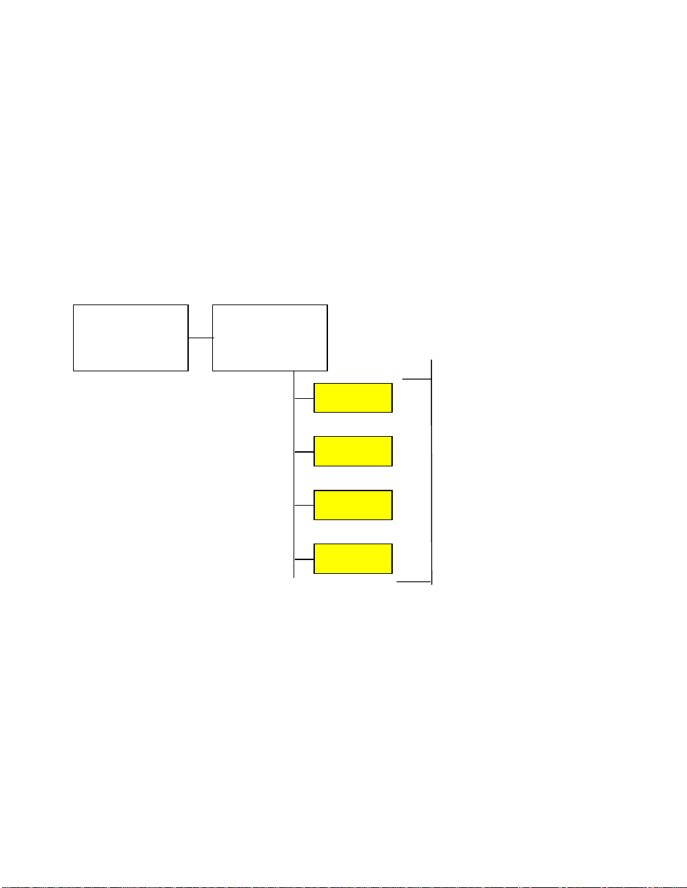
The Continuum I/O system is comprised of a series of modules separated by function
that connect via a common elect r ic al c om m unic ations bus. Each functional component is
enclosed in a plastic case c ontaining all of its connections t o the out s ide wor ld. Modules
are connected to a central c ontroller via a standard five conduc tor connector.
The Continuum system inc ludes at least one power supply and a single controller
module. I/O modules pr ov ide the controller with the ability to int er face with the outside
world. They connect direc tly and communicate with the CPU. The following is a t y pic al
architecture drawing of a Continuum System:
Power Supply
Controller
I/O Modules
Continuum I/O modules ar e av ailable in INPUT, OUTPUT, MIXED and DISPLAY
varieties.
2
Andover Controls
Page 9

The INPUT modules available are:
UI-8-10; Univers al Input Module
•
UI-8-10-10V; Univ er s al Input Module
•
DI-6 AC; AC Digital Input Module
•
DI-6 AC HV; AC Digital Input Module
•
DI-8; Digital I nput Module
•
DM-20; Digital Input/Output Module (for DIO- 20)
•
MI-6; MilliAmp Input Module
•
The OUTPUT modules available are:
AO-4-8-O; Analog Out put Module (with override)
•
AO-4-8; Analog Out put Module
•
DO-4-R-O; Relay Output Module (with override)
•
DO-4-R; Relay Output Module
•
DO-6-TR; Triac Output M odule
•
LO-2-O; Lighting O utput Module (with override)
•
LO-2; Lighting O utput M odule
•
The MIXED modules available are:
AC-1; Door, Access Control, Wiegand Module
•
AC-1-ABA; Door, Access Control, ABA Module
•
The DISPLAY modules available ar e:
LB-8; 8-Channel LED Bar Dis play / 8 Push Button Module
•
LS-8; 8-Channel, 3 Digit 7- S egm ent LED Dis play / 16 Push Button Module
•
LC-1; 2-Line LCD Display/ 12 P us h B utt on M odule
•
VM-1; Voice Record and Playback Module
•
GA-40; Graphic Annunc iator Panel
•
Continuum I/O System Reference
3
Page 10
Mechanical Installation
q
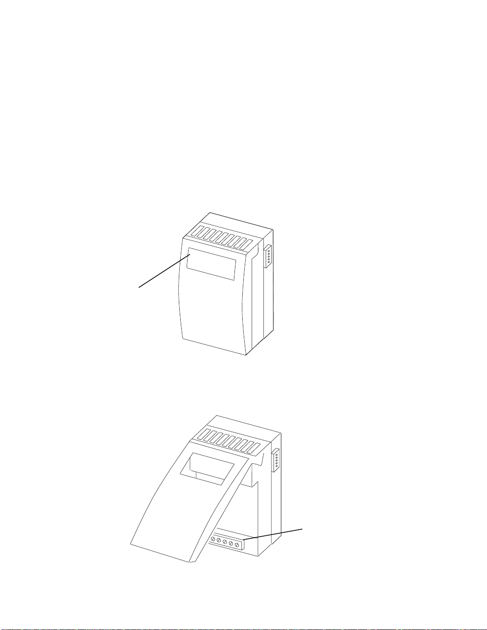
Each I/O module, except the Display v ar iety, is enclosed in the same standard plas tic
case that is designed to be mounted on a standard DIN rail or fastened to a panel.
Note: In order to meet agen cy requirements, it is necessary that the modules along
with the power supply and controller be housed in another metal enclosure i.e., a
NEMA box or the new Andover Controls Cont in uu m enclosure.
The standard I/O module plastic case is illustrated below:
Status Indicators
& some switches
Status indicat or s and oper ator switches are located on the indicat or panel. Other
switches available for m odule c onfiguration may be access ed by lifting the hinged door to
the module as shown.
Connections to
controlled/sensed
uipment
e
4
Andover Controls
Page 11
Wiring to controlled points or sensors is accomplished via a standard removable screw
terminal block locat ed at the bottom of the module behind the door. A n open area at the
bottom of the case allows wires to exit in an appropriate manner.
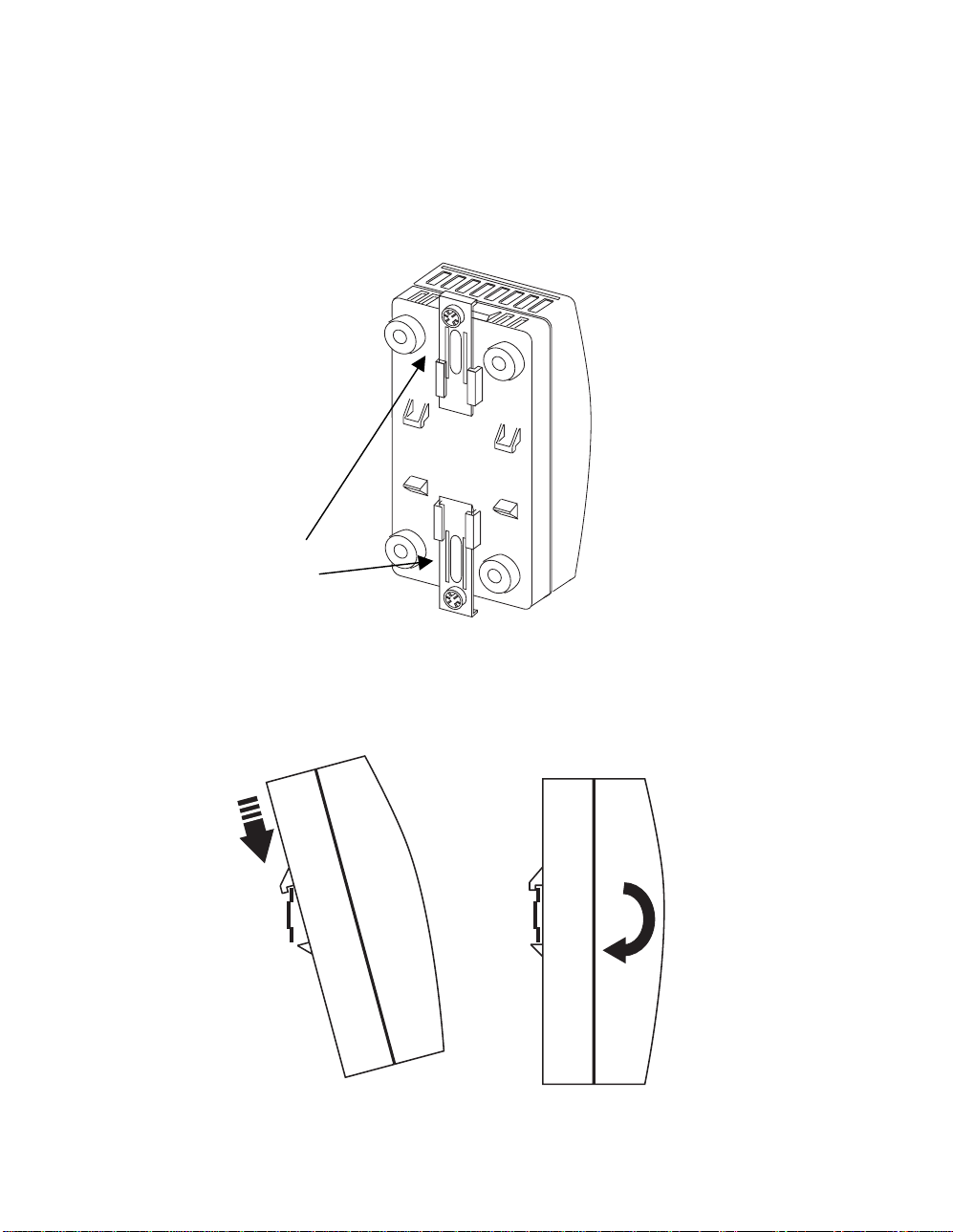
On the back of each module are molded DIN r ail guide fingers. The design allows the
module to easily hook onto and s lide along a s tandard DIN rail.
Locking Fingers
With the mounting brack ets extended outward, hook the module ont o the DI N r ail as
shown below:
Continuum I/O System Reference
5
Page 12

Slide the module into posit ion.
Press the lower mounting bracket inward until it locks the module in place.
Press the upper brac k et int o its loc k ed pos ition as well.
Once the module is in the desired pos ition, it is locked to the rail by pushing the bot tom
clamps inward. After the bottom is secure, press the top clamp inward to c om plete the
operation.
6
Andover Controls
Page 13
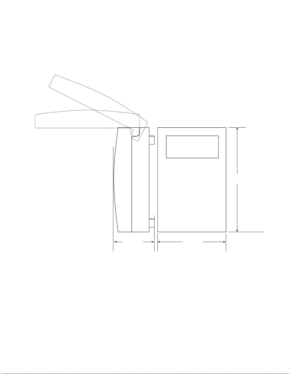
Overall Dimens ions
The overall dimensions of the standard I/O case are as shown:
6.70''
(170.2 mm)
2.50 ''
(63.5 mm)
3.50 ''
(88.5 mm)
Continuum I/O System Reference
7
Page 14
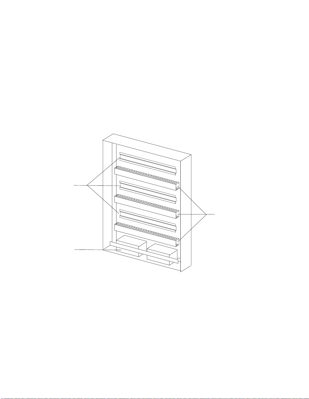
Enclosure-Mounted Modules
The modules that are designed t o be m ounted to the new Andover Controls Continuum
enclosure fit int o openings left by removing panels in the front door .
The new enclosure provides a plac e to mount a power supply, CPU and up to ten DIN rail
mounted I/O modules. Sev er al dis play m odules c an be aff ix ed to the front panel.
The enclosure is a 6” deep NEMA box with int egr al dis play panels , DIN rails, cable
troughs and a batter y st or age c ompart m ent.
DIN Rail
Cable Trough
Battery
Storage
The enclosure feat ur es three DIN rails and cable management accessor ies . Use of t he
new enclosure is not required, however, it provides a convenient method of constructing
small local systems.
8
Andover Controls
Page 15
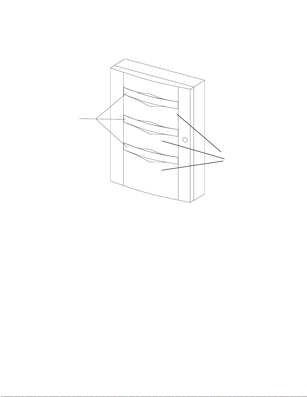
The front door of the enclosur e c ontains removable sections into whic h s pec ial oper ator
display and control modules m ay be m ounted. Alternately, Plexiglas panels m ay be us ed
to view the status lights of all internal modules when the door is closed.
Removable
Display Panels
Spacers for
Additional Displays
Continuum I/O System Reference
9
Page 16

Power-CPU Connections
The Continuum NetCont r oller CP U m odule inc ludes a c onnec tor on the upper right
side of its case for further distribution of the 24 VDC input power and special I/O
communications signals to all I/O modules. Continuum I/O modules us e these signals
for power and communications as well.
The power-I/O connec tor is a five pin male assembly that is designed to easily ins er t
directly into t he left s ide ( input) connector of any I/O module. The signals wit hin that
connector are as follows:
PIN Function
5 +24 VDC
4 24 VDC Return
3 Ground
2 Comm B
1 Comm A
5
The system power supply gener ates a +24 VDC source for all modules in the system.
This power source is received through the input power connector on the left side of
the CPU module and sent through t o pins 4 and 5 of this connec tor. Pin 3 (Ground) is
intended as a signal ground connect ion.
Communications between the CPU and I/O modules is through a two-signal s er ial
interface that can be internally configured as eit her RS 485 or Echelon LON FT T-10.
Pins 1 and 2 (Comm B and Comm A) provide the elect r ic al c onnec tion for this
interface.
10
Andover Controls
Page 17

Connection of I/O Modules
y
The CPU can directly connect to I/O without the use of cables through a syst em of
built-in plugs and jacks. All I/O modules include two complementary module interconnectors.
Creating a system is as simple as physically plugging the modules together.
Power Suppl
CPU
I/O
I/O
In vertical extended systems, I/O modules may be located above or below other
modules. In this case, cable as s em blies br idge the I/O modules together.
The cable necessary to connect the CPU and external I/O modules is five c onduc tor
and would be attached using a plug-in screw terminal connector. Connection
between the modules is one-to-one straightforward wir ing as s hown below:
5
4
3
2
5
4
3
2
This connector is available f r om A ndov er Controls under part number 01-2050-283;
Wieland manufactur es it under par t number 25.340.0553.0.
Continuum I/O System Reference
11
Page 18

Maximum Number of I/O Modules
There is no operational limit to the number of I/O modules connected to the CPU except
the capacity of the power s upply . It is pos s ible to insert auxiliary power supplies int o the
I/O bus to increase the num ber of modules s uppor ted.
To determine the maximum number of I/O modules your system can support, subtract the
power requirements f or eac h module fr om the max im um available f r om y our power
supply.
PS 120/240 AC 50 U, UPS power supply provides 35 Watts of power
•
PS 120/240 AC 50, non-UPS power s upply pr ov ides 50 Watts of power
•
PS –48 DC 50, Battery operated power s upply pr ov ides 50 Wat ts of power
•
NetController requires 15 Watts of power
•
Start by subtracting the NetController from the power available from your power supply.
PS 120/240 AC 50 U
35 – 15 = 20 Watts of available power for I/ O
PS 120/240 AC 50
50 – 15 = 35 Watts of available power for I/ O
PS –48 DC 50
50 – 15 = 35 Watts of available power for I/ O
The power requirements for each I/O module is listed in the
Reference Guide
ACC # 30-3001-499 and can be found on individual dat a s heets.
Continuum I/O System
Maximum Length of I/O Bus
A repeater is necess ar y if the cable lengths get too long. The following are
recommendations regar ding c able lengths for both RS-485 and FTT- 10 interfaces:
RS-485 Repeater required if lengt h is >2000 ft. (610 m) or after 32 modules.
FTT-10 Repeater required if lengt h is >8858 ft. (2700 m) bus topology
>1640 ft. (500 m) free topology
Connecting Remote I/O Modules with RS-485
The Continuum system allows I/ O modules to be placed in a remote location from the
CPU (NetController) . However, long cable lengths can cause s ignal c om m unic ations
problems on the Power/I- O bus.
When locating an I/O module remotely it is necessary to add a 120
terminator to the
Ω
bus to compensate for the distance. The terminator must be connec ted at both ends of
the bus for proper operation.
12
Andover Controls
Page 19
Terminat i on Guidel ine s
The following are typic al ins tallations that indicate the placement of the terminator:
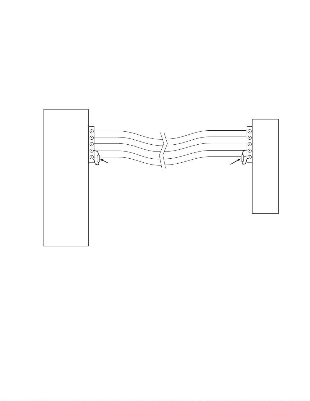
Simple CPU and 1 remote I/O Module:
The I/O Bus that needs to be term inated is the one formed by the cable attaching the
remote module to the CPU. In this c as e, a t erminat or r es is tor is connected across the
communications lines ( pins 1 & 2) directly at the NetController and again at t he r em ote
I/O module.
CPU
5
4
3
2
1
120 Ω
Resistor
120 Ω
Resistor
5
4
3
2
1
Remote
I/O
Module
Continuum I/O System Reference
13
Page 20

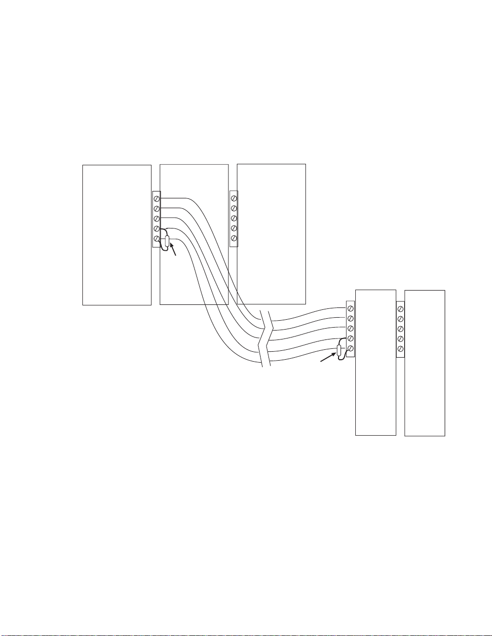
CPU with local and 1 remote I/O Module:
The I/O Bus that needs to be term inated is the one formed by the cable that starts at
the NetController and ends at the remote module. The bus that extends from the
NetController thr ough the local I/O stack does not need terminat ion. In this case, the
terminator res is tor is connected directly across the c om m unic ations lines ( pins 1 & 2) at
the NetController and again at the remote I/O module.
CPU
120 Ω
Resistor
Local
I/O
5
4
3
2
1
5
4
3
2
1
Local
I/O
120 Ω
Resistor
5
4
3
2
1
Remote
I/O
Module
14
Andover Controls
Page 21
CPU with local and several rem ote I/O Modules:
The I/O Bus that needs to be term inated is the one formed by the cable that starts at
the NetController and ends at the first remote module. The bus that extends from the
NetController thr ough the local I/O stack and the one that st arts at t he firs t rem ote
module and extends through s ubs equent modules do not need termination. In this
case, the terminat or r es istor is connect ed dir ec tly across the communications lines
(pins 1 & 2) at the NetController and again at the first remote I/O module.
CPU
120 Ω
Resistor
Local
I/O
5
4
3
2
1
5
4
3
2
1
Local
I/O
120 Ω
Resistor
5
4
3
2
1
Remote
I/O
Module
5
4
3
2
1
Remote
I/O
Module
Continuum I/O System Reference
15
Page 22
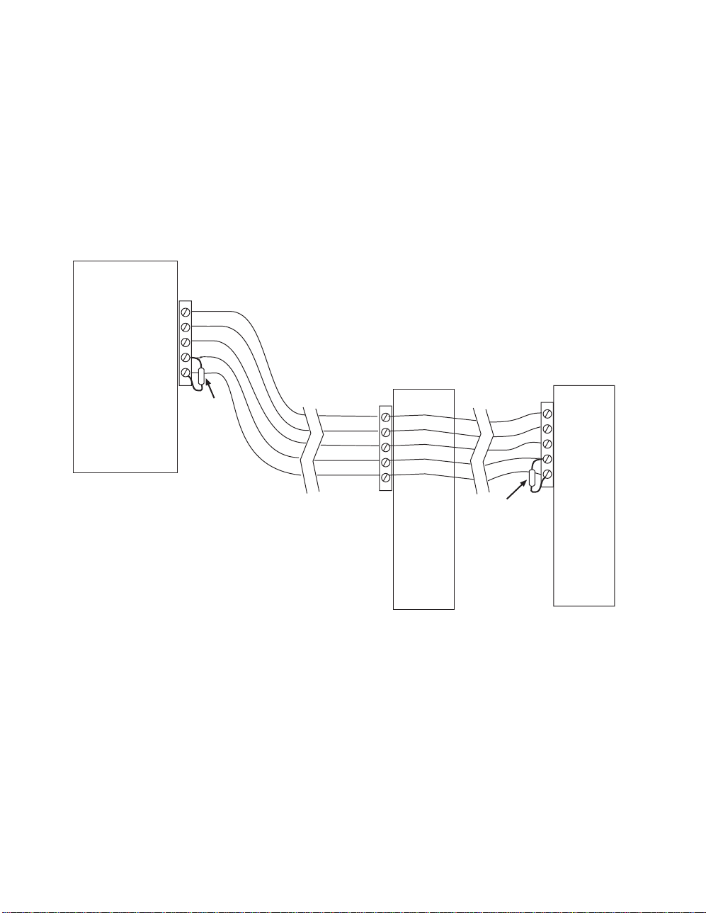
CPU with two remote modules s epar ated by distance:
The I/O Bus that needs to be term inated is the one formed by both cables on either
end of the first remote I/O m odule. In this case, the bus begins at the NetCont r oller ,
flows by the first remote module and ends at the second. The terminat or resis tor is
connected directly ac r os s the communications lines (pins 1 & 2) at the NetContr oller
and again at the last remote I/ O module. If the last module is actually a stack of
directly connect ed I/ O modules , the terminator is placed at the fir s t module of the
stack as indicated in the scenario described on the previous page.
CPU
5
4
3
2
1
120 Ω
Resistor
5
4
3
2
1
Remote
I/O
120 Ω
Resistor
Module
5
4
3
2
1
Remote
I/O
Module
16
Andover Controls
Page 23

Individual Module Characteristics
This section of the document describes the various I/O modules and presents interfacing
information. E ac h module is pres ented in its own mini-section. The part number
designator for the module being described is printed on the outer edge of each page.
General Wiring Concerns for All Modules
Do not remotely ground any part of t he input sensor wiring. Remote grounds c onnec ted
to the return term inal c ould m ak e the syst em oper ate incorrectly or damage the
equipment. The signal r eturn is not true earth ground. It is an elect r onic r eferenc e point
necessary to int er pr et t he sensor pr oper ly .
It is recommended that you r un input wiring in a conduit separate from AC power or
output wiring and avoid long wiring runs .
For reliable input operat ion, follow these input wiring guidelines :
Never lay wires across the surfac e of a printed circuit board.
•
Wires should never be wit hin 1 in. or 25 mm of any com ponent on a printed
•
circuit board.
Use shielded input wire.
•
Terminate the shield of the input wires at one end of the run only—preferably at
•
the end where your I/O module is located.
Be careful when str ipping wir e not to drop small pieces of wire inside the cabinet.
•
Don’t run your input wiring in the same conduit with AC power.
•
Don’t run your input wiring in the same conduit with your output wiring.
•
Grounding the Modules
Each module includes a screw terminal connection for Earth ground. It is important that
this connection be made as c los e to the module as pos s ible.
Caution
Do not externall y ground any inpu t sign al connected to the module. This may
damage the unit. Sign al return terminals are not connected to Earth Ground.
Continuum I/O System Reference
17
Page 24

18
Andover Controls
Page 25
UI-8-10
The UI-8-10,
Continuum
’s universal input module, pr ov ides 8 univ er s al inputs, software
configurable as voltage, thermistor, digit al, or counter point types. Each point c an als o be
configured as a supervis ed input for security monitoring, pr ov iding s epar ate indication of
alarm and trouble conditions . This module is a perfect choice f or any mix of temper ature,
pressure, flow, status points, and similar inputs in a control system, with a 0-5 volt input
range and 10 bit A/D conver s ion.
The UI-8-10-10V m odel is available f or 0- 10V applic ations. It provides t he identical point
type selection; but is equipped with individual voltage divider DIP switches on each input,
allowing each to be configured f or a 0- 10 v olt range.
FEATURES
POWER
COMM
STATUS
USE COPPER CONDUCTORS ONLY
USE COPPER CONDUCTORS ONLY
SWITCH SETTINGS
INPUT TYPE REFERENCE RANGE
TEMPERATURE ON 5 V
5V RANGE OFF 5 V
10V RANGE OFF 10 V
REFERENCE
RESISTOR
READER
OFF ON
POWER
+ 5V, 100mA
+ 12V, 180mA
SUPERVISED
INPUTS(0-5V)
READER
+
V
IN1
123456789101112
12
1
L
G
DC
A
N
E
L
A
T
D
D
K
A
U
ANALOG INPUTS
X
/
/
1
0
IN3 IN4 RETIN2 RET IN5 IN6 RET IN7 IN8 RET
4
56
3
ON
OFF
AUTO
IN1
IN2
IN3
IN4
IN5
IN6
IN7
23
D
IN8
O
O
R
7
R
E
X
8
1-DOOR
VOLTAGE
RANGE
5V 10V
CONTACT RATING:
DIGITAL OUTPUTS
1-DOOR
R
E
T
10 11 12
9
COMMISSION
RESET
UI-8
ON
OFF
AUTO
13 14 15
OUT 2
OUT2
•
•
•
•
8 Universal Inputs
10 bit Resolution
0-5V or 0-10V Input Range
Supports Voltage, Thermistor, Digital,
Counter and Supervised Elec trical
Types
•
Pull-up Resistor Disable S witches
Continuum I/O System Reference
19
Page 26

UI-8-10
SPECIFICATIONS
ELECTRICAL
Power Consumption:
Overload Protection:
INPUTS
Number of Inputs:
Input Types:
Input Protection:
Input Impedance:
Input Connections:
Voltag e : UI-8-10 (0-5V) UI-8-10-10V (0-10V mo d e)
Range: 0-5 volts 0-10 volts
Resolution: 5 mV 10 mV
Accura c y : ±15 mV (±0.3% FSR) ±40 mV (±0.4% FSR)
Filtering: Corner Frequency at 15 Hz, –20 db/decade
Calibration: Permanent (factory)
0.7 Watt at 24VDC max.; normally provided by
supply module.
0.5A resettable fuse with transient voltage suppressor (TVS) and
reverse polarity protection.
8 Universal inputs; 10 bit resolution
Voltage, Thermistor, Digital, Counter, and Supervised
24V AC/DC allowed to any single input
(40V transient voltage suppressor on each input – UI-8-10-10V)
5 MΩ w/pull-up disabled; 10 KΩ w/pull-up enabled – UI-8-10
(4.4 KΩ w/pull-up enabled in 0-10V mode UI-8-10-10V)
Two-piece, 13-position removable terminal block
Continuum
power
Thermistor:
Type: 10 KΩ, Type III Thermistor
Range: -30 to 230°F
Resolution: 40 to 100°F range 0.20°F typical
Accuracy: 40 to 100°F range ± 1.0°F (includes 0.36° error for thermistor)
Digital & Counter:
Input Type: Contact Closure
Frequency: 4 Hz max.
Pulse Width: 125 ms min.
Supervised:
Input Type: Single or Double Resistor Supervision, Parallel or Series Circuit
20
Andover Controls
(-34 to 110°C)
(4 to 38°C) (0.11°C typical)
(4 to 38°C) (±0.55°C)
Page 27

UI-8-10
I/O Connecti ons
The actual input connections are locat ed on a twelve-position removable screw terminal
connector located at the bottom of the module. Input wires s hould enter from either the
top or bottom wiring tr oughs , and should c om e from the left side of the rack (by
convention).
The inputs are labeled IN1, IN2, IN3, and so forth. Each pair of inputs is f ollowed by a
connection labeled RET f or the input signal return, resulting in a sequence of IN1, IN2,
RET, IN3, IN4, RET, and so on. For any given input, you should use the closest ret ur n
terminal either bef or e or aft er that input—the next return terminal goes with the next two
inputs, and so on.
The twelve-posit ion c onnec tor allows for eight inputs and f our signal returns.
The diagram below indicates wher e eac h input number is located in the term inal bloc k .
Shield/Earth G r ound
1. IN 1
2. IN 2
3. RETURN
4. IN 3
5. IN 4
6. RETURN
7. IN 5
8. IN 6
9. RETURN
10. IN 7
11. IN 8
12. RETURN
POWER
COMM
STATUS
COMMISSION
RESET
UI-8
USE COPPER CONDUCTORS ONLY
USE COPPER CONDUCTORS ONLY
INPUT TYPE REFERENCE RANGE
TEMPERATURE ON 5 V
5V RANGE OFF 5 V
10V RANGE OFF 10 V
READER
POWER
+
V
IN1
123456789101112
12
SWITCH SETTINGS
REFERENCE
RESISTOR
OFF ON
+ 5V, 100mA
+ 12V, 180mA
READER
L
G
DC
A
N
E
L
T
D
D
K
A
/
/
1
0
IN3 IN4 RETIN2 RET IN5 IN6 RET IN7 IN8 RET
Continuum I/O System Reference
4
56
3
1-DOOR
ON
OFF
AUTO
IN1
IN2
IN3
IN4
SUPERVISED
IN5
INPUTS(0-5V)
IN6
IN7
1
23
D
IN8
A
R
O
U
E
O
ANALOG INPUTS
X
X
R
7
8
R
E
T
9
10 11 12
ON
OFF
AUTO
VOLTAGE
RANGE
5V 10V
CONTACT RATING:
DIGITAL OUTPUTS
1-DOOR
13 14 15
OUT 2
OUT2
21
Page 28

UI-8-10
Input Circ uitr y
UI-8-10 Inputs ar e essent ially v oltmeters. Universal input s can be conf igur ed through
software to become one of fiv e diff er ent input circuits:
Temperature
♦
Voltage
♦
Digital
♦
Counter
♦
During configuration, the value of the Electrical Type att r ibute you select tells the
controller how to int er pr et the reading from each input. Each Universal input is read every
100 milliseconds. This r eading is independent of the controller s c an time.
The following is a simplif ied s c hem atic of both the UI-8-10 and the UI-8-10- 10V Univ er s al
inputs:
Vref
Vref
IN x
RET
Rref
Swdis
UI-8-10
IN x
RET
2.21K
0-5V
Range
0-10V
2.21K
UI-8-10-10V
Rref
Swdis
The main differenc e between the two is the UI-8-10-10V circuit inc ludes a s witch
selectable front - end v oltage divider that effectively divides the 10V input signal by two.
22
Andover Controls
Page 29

UI-8-10
Each input includes a low-pass filter after the pull-up form ed by a series r es is tor and a
parallel capacitor. The resistor is utilized f or ov er-voltage protection in limit ing c ur r ent t o
two protection diodes ( not shown). Note also that all input returns ar e c ombined and must
be directly connect ed to earth ground. It is possible to have mor e than one input s har e a
single return wire. K eep in m ind that the current through each input is approx im ately
0.3mA, so voltage drops oc c ur with long r uns of sm all gauge wir e.
Pull-up Referen ce Resistor Selection Switches
In some measuring instances it is desirable that there be no pull-up resistor. Instead of
physically removing or c utting the resistor off the printed circuit board, the input module
includes a pull-up resistor s elec tion switch (labeled Swdis in t he diagr am ) for each input
position. This s witch allows you to select whether or not you want a pull-up res is tor in the
circuit. A small 8-pos ition switch module is accessible f r om the front of the module when
the door is opened.
Slide marker
moves left and right
12345678
O N
These switch modules are com m only c alled “ DIP Switches” and require a small object
such as the tip of a pen or a small screwdriver to operate them. Each switch position acts
as a “slide switch”. Pr es s ing the rais ed s lide m ar k er to t he side mark ed “ on” closes or
enables the switch. To open or dis able the switch position, press the s lide m ar k er over to
the “off” side.
Continuum I/O System Reference
23
Page 30

UI-8-10
Input Voltage Range Selection Switches (UI-8-10-10V Only)
The UI-8-10-10V m odule allows y ou to choose from two input voltage ranges. S elec tion
is accomplished by using a switch arrangement that is similar to the operation of the pullup resistor swit c hes. The Voltage Range switches allow you to select a range (0-5 V ) or
(0-10 V) for each input.
The 0-5V range allows connections to signals that do not exceed 5. 00V . T he 0-10V range
allows connection to signals up to 10.00V. In this mode the circuit actually us es the same
input measuring circuit as the 0-5V range, however, it div ides the voltage present by two
thereby limiting t he internal circuitry to 0-5V. When you r ead a 0- 10V input the actual
reading will be 0-5V. You must adjust your readings for the higher range v ia formula.
Switching to 10V input s dramatically lowers the impedance of the input to
This small 8-posit ion s witch module is located to the right of the pull-up selector switch
and is accessible from the f r ont of the m odule when the door is opened.
4.4 KΩ.
24
Andover Controls
Page 31
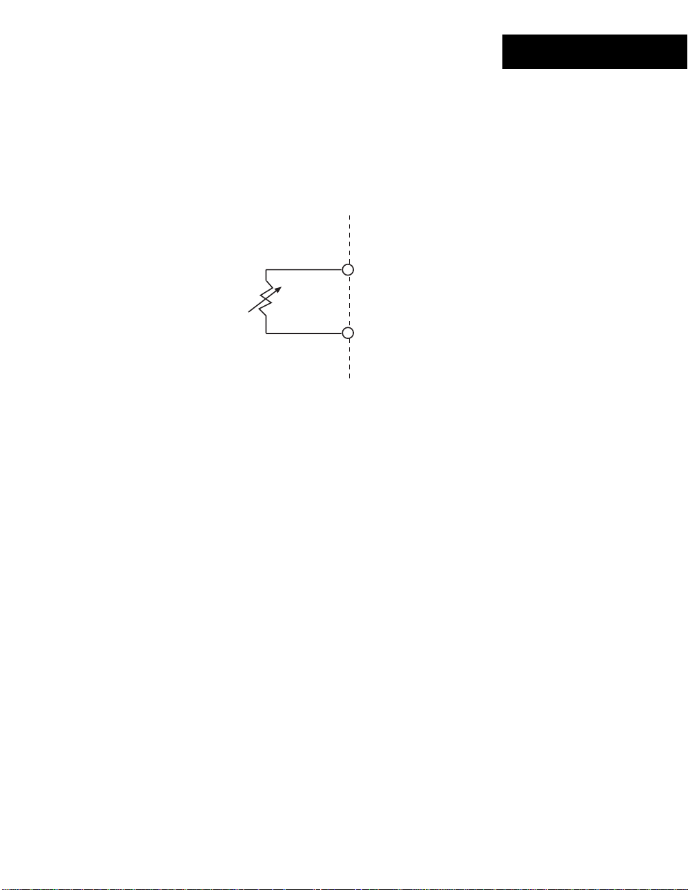
Measuring Temper at ur e
UI-8-10 inputs may be conf igur ed to sense temperature by configuring one of the
module’s inputs appropriat ely . This is done by setting t he Elect r ic al Type to either
or
Temp (DEG F)
ACC Temp (DEG C)
input terminal. The following is a schematic repres entation of the connection:
Thermistor
One lead connects t o a numbered input terminal, the other to a return terminal.
To use the input for temperature sensing, the pull-up refer enc e r es is tor must be
connected into the c ir c uit, therefore,
be placed in the ‘on’ position
. When the input point is configured as a t emperat ur e
input, the cont r oller utilizes a look-up table to convert f r om a volt age reading to a
temperature reading in degr ees Fahrenheit or Celsius.
. Connect a resistive therm istor s ens or to that
IN x
RET
the reference resistor switch for th is input must
UI-8-10
ACC
Caution
Never apply a voltage to a therm is tor—doing so alters the thermistor’s ac c ur ac y and
reliability. In fact, it’s a good idea to replace any thermistor that has had any sort of
voltage applied to it.
Maximum Wire Runs for Thermistors
To keep thermistor er r or s minimal, limit the length of wire runs to the maximum for the
gauge wire you select.
The following two pages include three tables that indicate the maximum length runs for
wires of various gauges to keep errors within certain temper ature limits when using
thermistor elem ents.
Continuum I/O System Reference
25
Page 32

UI-8-10
Wire Gauges and Corresponding Maximum Runs for
Sensing Temperatures Up to 70 °F (21 °C)
Gauge
#14 26,700 ft. 13,300 ft. 5,300 ft.
2
2.5 mm
#16 16,700 ft. 8,300 ft. 3,300 ft.
2
1.5 mm
#18 10,500 ft. 5,200 ft. 2,100 ft.
2
1.0 mm
#20 6600 ft. 3,300 ft. 1,300 ft.
2
0.5 mm
#22 4,100 ft. 2,000 ft. 800 ft.
0.35 mm
2
°F (.28 °C) Error 1/4
1/2
8150 m 4000 m 1600 m
5120 m 2500 m 1000 m
3200 m 1600 m 640 m
2000 m 1000 m 400 m
1250 m 600 m 250 m
°F (.14 °C) Error 1/10
°F (.06 °C) Error
Wire Gauges and Corresponding Maximum Runs for
Sensing Temperatures Up to 100 °F (38 °C)
Gauge
#14 12,600 ft. 6,300 ft. 2,500 ft.
2
2.5 mm
#16 7,900 ft. 3,900 ft. 1, 500 ft.
2
1.5 mm
#18 5,000 ft. 2,500 ft. 1, 000 ft.
2
1.0 mm
#20 3,100 ft. 1,500 ft. 600 ft.
2
0.5 mm
#22 1,900 ft. 900 ft. 300 ft.
0.35 mm
26
Andover Controls
2
°F (.28 °C) Error 1/4
1/2
°F (.14 °C) Error 1/10
3800 m 1900 m 760 m
2400 m 1200 m 450 m
1500 m 760 m 300 m
950 m 450 m 180 m
580 m 275 m 90 m
°F (.06 °C) Error
Page 33

Wire Gauges and Corresponding Maximum Runs for
Sensing Temperatures Up to 150 °F (65 °C)
UI-8-10
Gauge
°F (.28 °C) Error 1/4
1/2
°F (.14 °C) Error 1/10
°F (.06 °C) Error
#14 4,100 ft. 2,000 ft. 800 ft.
2.5 mm
2
1250 m 600 m 240 m
#16 2,600 ft. 1,300 ft. 500 ft.
1.5 mm
2
800 m 400 m 150 m
#18 1,600 ft. 800 ft. 300 ft.
1.0 mm
2
500 m 240 m 90 m
#20 1,000 ft. 500 ft. 200 ft.
0.5 mm
2
300 m 150 m 60 m
#22 600 ft. 300 ft. 100 ft.
0.35 mm
2
180 m 90 m 30 m
Continuum I/O System Reference
27
Page 34

(
)
UI-8-10
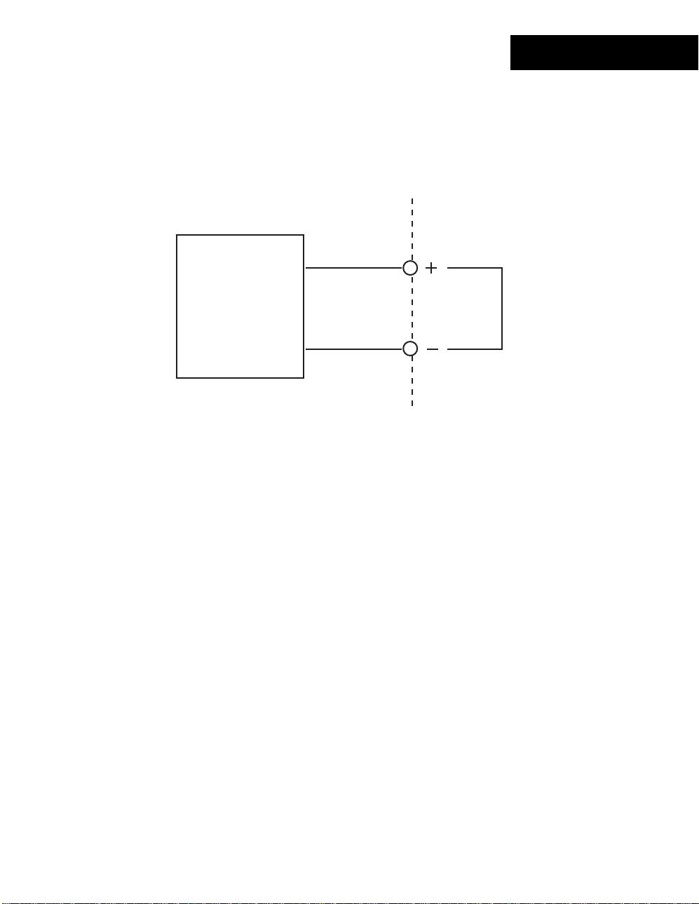
Measuring DC Voltages
The UI-8-10 inputs may be configured to sense DC voltage by setting the Electr ic al Type
to
Voltage
the module’s input specifications. The following is a s c hem atic representation of the
connection:
and connecting the input term inals to a DC voltage source within the range of
INx
+
V
-
RET
return
One lead connects t o the number ed input terminal, the other to a return term inal.
When interfacing to a voltage output sensor, specific information on the transducer may
be required. The pull-up res is tor of the input circuit will affect the output of the transducer.
It is suggested that you dis able ( s et to OFF) the pull-up reference resistor on voltage
•
inputs.
10V Input Notes
It should be noted that although the 10V input configuration allows y ou to measure a
higher voltage, you still read a value of 0-5V. You have to convert the reading in y our
program.
28
Andover Controls
Page 35

UI-8-10
Voltage Dividers
There are instances when it is nec es s ar y to interface to a voltage source that is higher
than the input range of the m odule. In these cases a voltage divider is necessar y .
DC input Voltage Divider
Two resistor values set up a ratio of voltage drop. These resistors m ust be sized
appropriately (value and wat tage) for the source being monit or ed. The higher the
resistance values, the less loading effect there will be on the source.
Vref
Rref
Swdis
R1
Vsource
IN x
R2
RET
The circuit shown abov e is a simple two-resistor voltage divider c onnec ted to one of the
UI-8-10 module’s inputs . The input circuitry of the module can m eas ur e a maximum of
either 5 Volts or 10 Volts (UI - 8- 10- 10V only ) . T her efore, the voltage measured across
Rinput must not exceed t his maximum .
In this case, be sure to switch the pull-up resistor out of the circuit .
Continuum I/O System Reference
29
Page 36

UI-8-10
Assuming you know the maximum voltage reading you are trying to measure (
source
V
),
perform the following st eps to determine the resistance values nec es s ar y to condition the
input for the module.
1. First, determ ine the current that will flow through the divider . Pick a value that your
source can supply. Let’s say 20 mA. This value will be represented by the var iable
total
in the following equat ions .
I
2. Determine the total resistance value required of the ent ir e div ider ( R1 + R2) to cr eate
20mA given the source voltage by s olv ing the following:
total
R
I
= V
source
total
Example, if you are measur ing a s our c e that can supply 0- 30 V:
total
= 30 V
R
20 mA
total
R
= 30 V
.02 A
total
R
= 1500
Ω
The current is const ant t hr ough the two resistors. Knowing this and the fact that our
input can’t exceed 5V ( or 10V) c an determine the value of the resistor labeled
3. Determine the value of
R
I
R2 = 5 V
2
by solving the following:
R
2
input
= V
total
(assuming you are solving for 0-5V input )
.02 A
2
R
= 250
Ω
Through subtraction, you can determine the remaining resis tor value:
30
Andover Controls
total
R
= R1 + R
R1 = 1500 Ω - 250
R1 = 1250
2
Ω
Ω
2
.
R
Page 37

UI-8-10
Sensing Digital Inputs or Contact Closures
Digital input points are des igned to allow the monitoring of logic lev el s ignals or c ontact
closures across an input (contact wired between the input and r eturn).
When monitoring a digital logic lev el s ignal, the pull-up resistor m us t be disabled ( s et
•
to OFF).
To sense a contact closure, the pull-up resistor must be enabled (set to ON).
•
IN x
Contact
Closure
RET
To sense a digital input or contac t clos ur e, configure an input point with an Elec trical
Type of
Digital
.
A digital input is consider ed “ ON” whenever the voltage across its input meets or exceeds
the ON Threshold. For a contact closure, this is 0 (zero) volts. Sim ilar ly , an OFF condition
meets, or is lower than, t he Off Thres hold. With a contact closure, this is the v alue of
Vref.
: When configuring a Digital point, there is a ‘Polarity’ att r ibute. If this attribute is
Note
enabled, readings are revers ed: ‘On’ will occur when the input is at Vref bec aus e the
contact is open, and ‘Off ’ oc c ur s when the input is at 0 volts because the contact is
closed.
Continuum I/O System Reference
31
Page 38

UI-8-10
Counting Pulsing Signals or Contact Closures
Counter inputs are designed to allow the monitoring of digital pulse trains or contact
closures across an input just like digital inputs, but t hey ac c umulate a total of those
closures and act like a c ounter.
Interfacing is s im ilar to a digit al input, however, you set the Electric al Type attribute to
Counter
When using an input as a counter, y ou must tak e into account the frequency of the input
signal being counted. Univers al inputs do not allow for very high s peed c ontact counting.
This module allows counting up to a maximum of 4 Hz or 4 contact closures or digital
pulses per second.
Counter Duty Cycle
To achieve the maximum counter frequency, the amount of time the signal is O N as
opposed to being OFF must be at least 125 m illis ec onds .
instead.
32
Andover Controls
Page 39
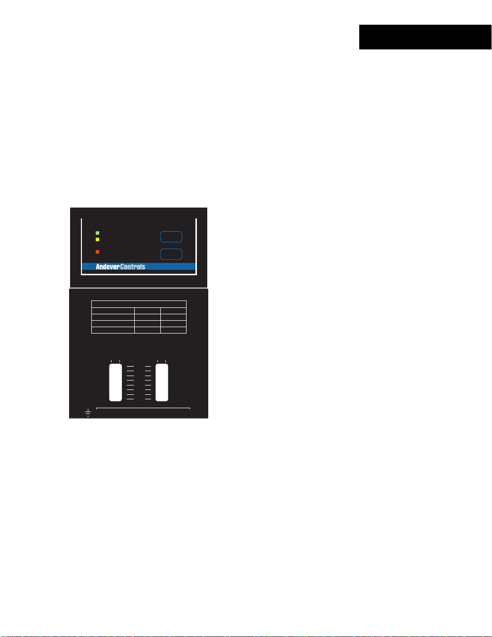
Status/Control Pa nel
Status In dic a t or s
The UI-8-10 module includes a c om plete indicator status panel on the fr ont of the
module.
UI-8-10
POWER
COMM
STATUS
COMMISSION
RESET
UI-8
This panel includes indicator s r epor ting on the status of the following:
POWER
COMM
STATUS
This green indicator illum inates when DC power is applied through the
Power/IO Bus.
This yellow indicator illum inates when data is transm itt ed from the
module to the NetCont r oller . In normal operation, data is only transm itted
when an input value changes.
This indicator will also flash periodically as the Net Controller checks the
I/O bus periodically.
This red indicator is nor m ally off . If it is alway s on or flas hing at a fast
rate there is a problem with the module.
This indicator can be m anually illum inated from the Continuum
workstation and used as a troubleshooting aid when locating a part icular
module. More inform ation on using this indicator may be found in the
Troubleshooting
section of this manual.
This panel also includes two oper ator switches that perform the f ollowing:
COMMISSION
After physic al installation and during configuration t hr ough the
Continuum workstation, pressing this butt on registers t he module’s
address with the syst em. For m or e information, refer to the section on
RESET
Configuring I/O
Should the module become inoperable, pr es s ing this button reset s the
found earlier in this manual.
module. It does not eras e its m emory.
Continuum I/O System Reference
33
Page 40

34
Andover Controls
Page 41
DI-6-AC
The DI-6-AC, Continuum ’s digital AC input module, has six digital ( “ wet”) AC inputs for
cost-eff ectiv e ON-OF F status indication of fan motor starter s , solenoid v alv es , control
relays, or external power s upplies , and similar applications t hat require a quick and easy
way to detect voltage. The DI-6-AC monitors the absence or presence of AC voltage
levels directly, with no interposing relays needed.
The DI-6-AC can monitor voltages from 24-120V. A DI-6-AC-HV model is also av ailable
for sensing higher volt ages120-240V. Both models can also ac c ept DC voltages. All
inputs are optically c oupled with 2500V isolation on each input f or nois e- free operation.
INPUT
INPUT
1
POWER
COMM
STATUS
USE COPPER CONDUCTORS ONLY
USE COPPER CONDUCTORS ONLY
WARNING:
HIGH VOLTAGE INSIDE-DANGEROUS TO
UNQUALIFIED PERSONS.
AVERTISSEMENT:
CAUTION:
MORE THAN ONE DISCONNECT MAY BE
REQUIRED TO DE-ENERGIZE THIS EQUIPMENT.
READER
POWER
+ 5V, 100mA
VOLTAGE RANGE(VAC) 50/60 HZ 20 - 132 90 - 280
INPUT CURRENT(mA) 0.4 - 9.0 0.4 - 3.0
+ 12V, 180mA
READER
+
G
DC
A
N
V
L
IN1
IN2 IN3 IN4 IN5 IN6
T
D
K
A
/
/
1
0
123456789101112
4
12
3
5
2
6
3
4
1-DOOR
ON
OFF
AUTO
HAUTE TENSION A L'INTERIEUR-DANGER
POUR LES PERSONNES NON-QUALIFIER.
DI-6-AC DI-6-AC-HV
SUPERVISED
INPUTS(0-5V)
DIGITAL INPUTS
1
23
L
E
D
R
A
R
O
D
E
U
E
O
T
X
X
R
56
7
10 11 12
9
8
COMMISSION
RESET
DI-6
OUT 2
ON
OFF
AUTO
CONTACT RATING:
24VAC/DC, 5A
DIGITAL OUTPUTS
OUT2
1-DOOR
13 14 15
FEATURES
6 optically-coupled, digital AC input
•
channels
Will accept AC or DC inputs
•
24-120V AC Input Range
•
120-240V AC Input Range (DI-6-AC-HV)
Continuum I/O System Reference
35
Page 42

DI-6-AC
SPECIFICATIONS
ELECTRICAL
Power Consumption:
Overload Protection:
INPUTS
Number of Inputs:
Input Protection:
Input Connections:
Input Range:
Input Current:
AC Voltage “ON” Threshold:
(Above this voltage is considered “ON”)
0.7 Watt at 24VDC max.; normally provided by
supply module.
0.5A resettable fuse with transient voltage suppressor (TVS) and
reverse polarity protection.
6 Digital AC voltage inputs
2500V isolation on each input
Each input has a 270V MOV.
Two-piece, 13-position removable terminal block
DI-6-AC DI-6-AC-HV
20-132 Vrms 90-250 Vrms
5 mA max . 2 mA max.
DI-6-AC DI-6-AC-HV
16 Vrms 75 Vrms
Continuum
power
AC Voltage “OFF” Threshold:
(Below this voltage is considered “OFF”)
Input Resistance
Maximum Turn ON Tim e:
Maximum Turn OFF Time:
DC Input Voltage Range:
DC Input Current:
DC Voltage “ON” Threshold:
(Above this voltage is considered “ON”)
DC Voltage “OFF” Threshold:
(Below this voltage is considered “OFF”)
36
Andover Controls
(±5%): 30KΩ 200KΩ
8 Vrms 30 Vrms
20 mS 20 mS
60 mS 60 mS
20-132V 90-250V
5mA max. 2mA max.
20V 90V
12V 45V
Page 43

DI-6-AC
I/O Connecti ons
The actual input connections are locat ed on a twelve-position removable screw terminal
connector located at the bottom of the module. Input wires s hould enter from either the
top or bottom wiring tr oughs , and should c om e from the left side of the rack (by
convention).
The inputs are labeled IN1, IN2, IN3, and so forth. Each pair of terminals c or r es ponds to
one input. With both AC and DC signals t her e is no polar ity to observe during connection.
The diagram below indicates wher e eac h input number is located in the term inal bloc k .
Shield/Earth G r ound
IN 1
1.
IN 1
2.
IN 2
3.
IN 2
4.
IN 3
5.
IN 3
6.
IN 4
7.
IN 4
8.
IN 5
9.
10. IN 5
11. IN 6
12. IN 6
INPUT
POWER
COMM
STATUS
USE COPPER CONDUCTORS ONLY
USE COPPER CONDUCTORS ONLY
WARNING:
HIGH VOLTAGE INSIDE-DANGEROUS TO
UNQUALIFIED PERSONS.
AVERTISSEMENT:
CAUTION:
MORE THAN ONE DISCONNECT MAY BE
REQUIRED TO DE-ENERGIZE THIS EQUIPMENT.
INPUT
1
2
3
4
5
6
COMMISSION
RESET
DI-6
1-DOOR
ON
OFF
AUTO
HAUTE TENSION A L'INTERIEUR-DANGER
POUR LES PERSONNES NON-QUALIFIER.
OUT 2
ON
OFF
AUTO
READER
POWER
+ 5V, 100mA
VOLTAGE RANGE(VAC) 50/60 HZ 20 - 132 90 - 280
INPUT CURRENT(mA) 0.4 - 9.0 0.4 - 3.0
+ 12V, 180mA
READER
+
V
IN1
123456789101112
12
L
G
DC
A
N
E
L
IN2 IN3 IN4 IN5 IN6
T
D
D
K
A
/
/
1
0
4
56
3
DI-6-AC DI-6-AC-HV
SUPERVISED
INPUTS(0-5V)
DIGITAL INPUTS
1
23
D
A
R
O
U
E
O
X
X
R
7
8
CONTACT RATING:
24VAC/DC, 5A
DIGITAL OUTPUTS
1-DOOR
R
E
T
10 11 12
9
13 14 15
Continuum I/O System Reference
OUT2
37
Page 44
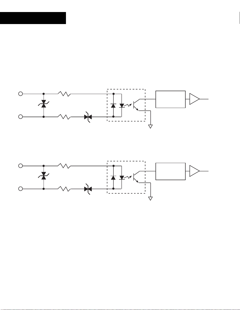
DI-6-AC
Input Circ uitr y
The following is a simplif ied s c hem atic of both the DI-6-AC and the DI-6-AC-HV Digital
Input module:
AC
IN x
RET
IN x
RET
275V
MOV
DI-6-AC
275V
MOV
15K
15K
100K
100K
10V
40V
OptoCoupler
AC to DC
Converter
AC
OptoCoupler
AC to DC
Converter
II
II
DI-6-AC-HV
The main differenc e between the two is the DI-6-AC-HV circuit includes a front end that
supports the higher v oltages.
38
Andover Controls
Page 45

DI-6-AC
Sensing AC or DC Digital Inputs
Digital input points are des igned to provide an ON or OFF reading of a signal (wired
between the input and ret ur n) . Norm ally y ou would as s oc iate an AC or DC voltage input
with a value measurement , however , the DI-6 modules include a voltage level tr igger that
senses the presence of a range of voltages and converts those readings to ON and OFF
indications.
AC
Signal
IN x
Polarity
Independent
DC
Signal
IN x
To sense an AC or DC digital input, conf igur e an input point with an Electrical T y pe of
Digital
.
The determination of ON or OFF is based upon the following measurement thr es holds :
DI-6-AC DI-6-AC-HV
AC Voltage “ON” Threshold:
(Above this voltage is considered “ON”)
AC Voltage “OFF” Threshold:
(Below this voltage is considered “OFF”)
DC Voltage “ON” Threshold:
(Above this voltage is considered “ON”)
DC Voltage “OFF” Threshold:
(Below this voltage is considered “OFF”)
16 Vrms 75 Vrms
8 Vrms 30 Vrms
20V 90V
12V 45V
: When configuring a Digital point, there is a ‘Polarity’ att r ibute. If this attribute is
Note
enabled, readings are revers ed: ‘ON’ will occur when the input is at the norm al OFF
threshold. OFF occur s at t he normal O N thres hold.
Continuum I/O System Reference
39
Page 46

DI-6-AC
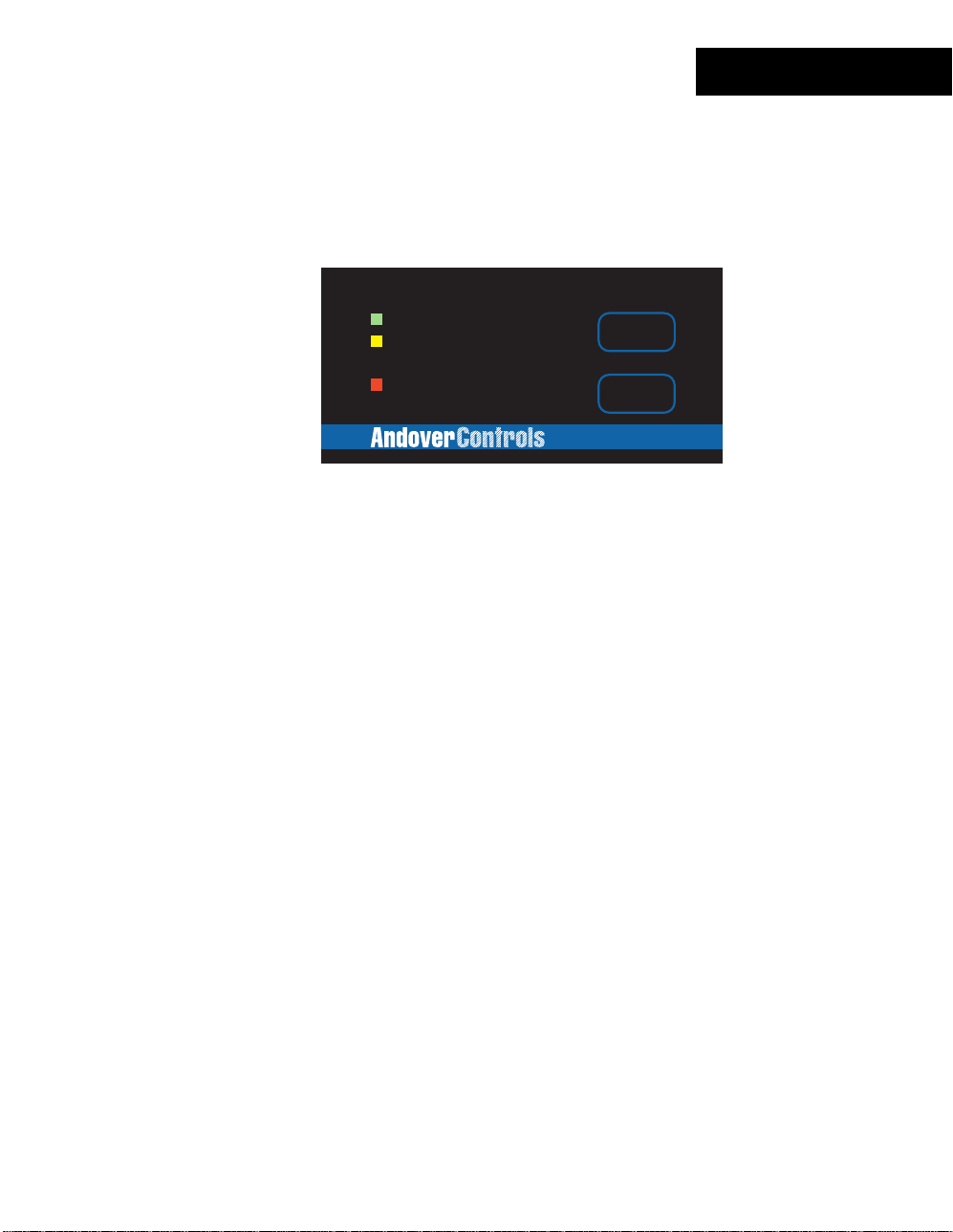
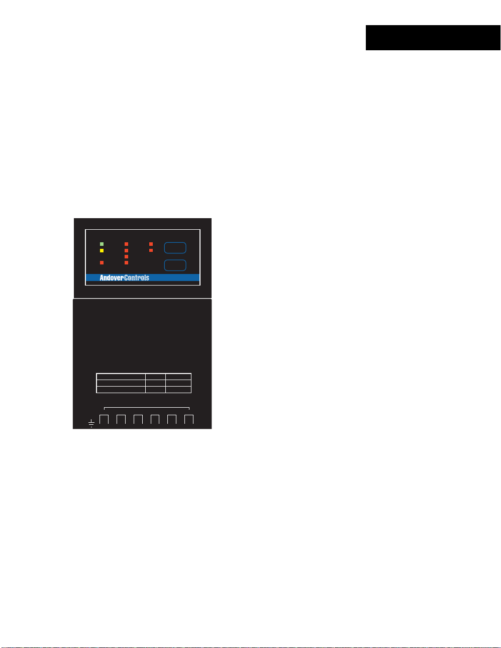
Status/Control Pa nel
Status In dic a t or s
The DI-6-AC module includes a com plete indicator status panel on t he front of the
module.
POWER
COMM
STATUS
INPUT
INPUT
1
2
3
4
5
6
COMMISSION
RESET
DI-6
This panel includes indicator s r epor ting on the status of the following:
POWER
COMM
STATUS
This green indicator illum inates when DC power is applied through the
Power/IO Bus.
This yellow indicator illum inates when data is transm itt ed from the
module to the NetCont r oller . In normal operation, data is only transm itted
when an input value changes.
This indicator will also flash periodically as the Net Controller checks the
I/O bus periodically.
This red indicator is nor m ally off . If it is alway s on or flas hing at a fast
rate there is a problem with the module.
This indicator can be m anually illum inated from the Continuum
workstation and used as a troubleshooting aid when locating a part icular
module. More inform ation on using this indicator may be found in the
Troubleshooting
section of this manual.
INPUT
40
Andover Controls
These red indicators ( one for eac h c hannel) illum inate when an ‘ON’
condition is sensed.
Page 47

This panel also includes two oper ator switches that perform the f ollowing:
DI-6-AC
COMMISSION
RESET
After physic al installation and during configuration t hr ough the
Continuum workstation, pressing this butt on registers t he module’s
address with the syst em. For m or e information, refer to the section on
Configuring I/O
Should the module become inoperable, pr es s ing this button reset s the
module. It does not eras e its m emory.
found earlier in this manual.
Continuum I/O System Reference
41
Page 48

42
Andover Controls
Page 49

The DI-8, Continuum’s digital input module, is used for cos t-effective sensing of multiple
dry digital inputs in applications such as equipment status monitoring or alarm point
monitoring. The DI-8 has eight digital inputseach can be software configured to ac c ept
a digital (contact c los ur e or 0-5 volt input) or counter signal. Counter frequency is 10Hz
on all eight inputs. I n addition, high speed counting up to 10KHz max. is available (via a
DIP switch) on Channels 1 and 2 for high-speed m etering and industrial applications .
40V transient suppr es s or s on all eight inputs protect against high voltage short duration
transients events. The DI-8 is designed to accept dry cont act inputs or 0-5 volts and can
withstand up to 24 VAC/DC continuous v oltage on four channels.
FEATURES
INPUT
INPUT
1
POWER
COMM
STATUS
USE COPPER CONDUCTORS ONLY
USE COPPER CONDUCTORS ONLY
5
6
7
8
COMMISSION
RESET
Allows interface to relay contact closures or 0-5v
•
digital signals.
2
3
4
DI-8
Allows high speed counting on channels 1 and 2.
•
1-DOOR
ON
OFF
AUTO
OUT 2
ON
OFF
AUTO
Input protection allows accidental wiring of
•
24VAC to inputs.
DI-8
READER
HIGH SPEED
POWER
COUNTER
+ 5V, 100mA
OFF ON
+ 12V, 180mA
READER
+
INPUTS: 0-5V/DRY CONTACTS
L
G
DC
A
N
E
V
L
T
D
D
DIGITAL / COUNTER INPUTS
K
A
/
/
1
0
IN3 IN4 RETIN2 RET IN5 IN6 RET IN7 IN8 RET
IN1
123456789101112
4
56
12
3
IN1
SUPERVISED
IN2
INPUTS(0-5V)
1
23
D
A
O
U
O
X
R
7
R
R
E
E
T
X
9
8
CONTACT RATING:
24VAC/DC, 5A
DIGITAL OUTPUTS
1-DOOR
10 11 12
OUT2
13 14 15
Continuum I/O System Reference
43
Page 50

DI-8
SPECIFICATIONS
ELECTRICAL
Power Consumption:
Overload Protection:
INPUTS
Number of Inputs:
Input Types:
Input Protection:
Input Impedance:
Input Connections:
Digital:
Input Type:
Pulse Width:
Curren t:
Counter:
Input Type:
0.8 Watt at 24VDC max.; normally provided by
supply module.
0.5A resettable fuse with transient voltage suppressor (TVS) and
reverse polarity protection.
8 Digital inputs
Digital or Counte r, software selectable
24V AC/DC applied to 4 channels max.
(40V transient protection on each input)
10KΩ pull-up resistor referenced to +5 volts
Two-piece, 13-position removable terminal block
Contact closure or 0-5V input
50 ms minimum
0.5mA
Contact closure or 0-5V input
Continuum
power
Channels 1 and 2 in HI-speed mode:
Frequency:
Pulse Width:
Curren t:
Channels 3 through 8; and Channel 1 and 2 in LO-speed mode:
Frequency:
Pulse Width:
Curren t:
44
Andover Controls
10KHz max.
50 µs min.
0.5mA
10Hz max.
50 ms min.
0.5mA
Page 51

I/O Connecti ons
The actual input connections are locat ed on a twelve-position removable screw terminal
connector located at the bottom of the module. Input wires s hould enter from either the
top or bottom wiring tr oughs , and should c om e from the left side of the rack (by
convention).
The inputs are labeled IN1, IN2, IN3, and so forth. Each pair of inputs is f ollowed by a
connection labeled RET f or the input signal return, resulting in a sequence of IN1, IN2,
RET, IN3, IN4, RET, and so on. For any given input, you should use the closest ret ur n
terminal either bef or e or aft er that input—the next return terminal goes with the next two
inputs, and so on.
The twelve-posit ion c onnec tor allows for eight inputs and f our signal returns.
The diagram below indicates wher e eac h input number is located in the term inal bloc k .
Shield/Earth G r ound
1. IN 1
2. IN 2
3. RETURN
4. IN 3
5. IN 4
6. RETURN
7. IN 5
8. IN 6
9. RETURN
10. IN 7
11. IN 8
12. RETURN
INPUT
POWER
COMM
STATUS
USE COPPER CONDUCTORS ONLY
USE COPPER CONDUCTORS ONLY
INPUT
1
2
3
4
5
6
7
8
COMMISSION
RESET
DI-8
1-DOOR
ON
OFF
AUTO
OUT 2
ON
OFF
AUTO
DI-8
READER
HIGH SPEED
POWER
COUNTER
+ 5V, 100mA
OFF ON
+ 12V, 180mA
READER
+
G
N
V
D
IN1
123456789101112
12
SUPERVISED
INPUTS(0-5V)
1
INPUTS: 0-5V/DRY CONTACTS
L
DC
A
E
L
A
T
D
DIGITAL / COUNTER INPUTS
K
A
U
X
/
/
1
0
IN3 IN4 RETIN2 RET IN5 IN6 RET IN7 IN8 RET
4
56
3
IN1
IN2
23
D
R
O
E
O
X
R
7
8
CONTACT RATING:
24VAC/DC, 5A
DIGITAL OUTPUTS
1-DOOR
R
E
T
10 11 12
9
OUT2
13 14 15
Continuum I/O System Reference
45
Page 52

DI-8
High Speed Counter Sel ection Switches
The DI-8 input module allows input c hannels 1 and 2 to be configured with the capability
of counting input pulses or c ontact closures at a rate of up to 10KHz. A selection switch is
included for each of t hes e two input c hannels . This switch allows you to select whether or
not you want the high speed input connec ted. A small 2-position swit c h module is
accessible from the front of the module when the door is opened.
Slide marker
moves left and right
1
2
O
N
These switch modules are com m only c alled “ DIP Switches” and require a small object
such as the tip of a pen or a small screwdriver to operate them. Each switch position acts
as a “slide switch”. Pr es s ing the rais ed s lide m ar k er to t he side mark ed “ ON” c los es or
enables the switch t her eby enabling high s peed c ounting. To open or disable the s witch
position, press the slide marker over to the “OFF” side.
46
Andover Controls
Page 53

Input Circ uitr y
The following is a simplif ied s c hem atic of the DI-8 Digital Input module:
5V
DI-8
10K
IN x
RET
Channels 1 and 2 can be configured to allow high s peed c ounting. The switches on the
front of the module substitute different value com ponents for the low pass filter formed by
the combination of R and C. These values s uppor t higher frequency inputs.
R
5V
II
C
Continuum I/O System Reference
47
Page 54

DI-8
Sensing Digital Inputs or Contact Closures
Digital input points are des igned to provide an ON or OFF reading of a signal (wired
between the input and ret ur n) .
Digital logic
Signal
IN x
RET
IN x
Contact
Closure
RET
To sense a digital input or contac t clos ur e, configure an input point with an Elec trical
Type of
Digital
.
A digital input is consider ed “ ON” whenever the voltage across its input meets or exceeds
the ON Threshold. For a contact closure, this is 0 (zero) volts. Sim ilar ly , an OFF condition
meets, or is lower than, t he Off Thres hold. With a contact closure, this is the v alue of
Vref.
: When configuring a Digital point, there is a ‘Polarity’ att r ibute. If this attribute is
Note
enabled, readings are revers ed: ‘On’ will occur when the input is at Vref bec aus e the
contact is open, and ‘Off ’ oc c ur s when the input is at 0 volts because the contact is
closed.
48
Andover Controls
Page 55

Counting Pulsing Signals or Contact Closures
Counter inputs are designed to allow the monitoring of digital pulse trains or contact
closures across an input just like digital inputs, but t hey ac c umulate a total of those
closures and act like a c ounter.
Interfacing is s im ilar to a digit al input, however, you set the Electric al Type attribute to
Counter
When using an input as a counter, y ou must tak e into account the frequency of the input
signal being counted. Inputs 3-8 do not allow for very high speed contac t counting. These
channels allow counting up to a max im um of 10 Hz or 10 cont act c los ur es or digital
pulses per second.
In high-speed mode, channels 1 and 2 c an be c onfigured (via front panel switc h) to count
to a maximum of 10Khz or 10,000 contact closures or digital pulses per sec ond.
instead.
DI-8
Counter Duty Cycle
To achieve the maximum counter frequency, the amount of time the signal is O N as
opposed to being OFF must be at least 125 m illis ec onds .
Continuum I/O System Reference
49
Page 56

DI-8
Status/Control Pa nel
Status In dic a t or s
The DI-8 module includes a complet e indic ator status panel on the fr ont of the m odule.
POWER
COMM
STATUS
INPUT
INPUT
1
2
3
4
5
6
7
8
COMMISSION
RESET
DI-8
This panel includes indicator s r epor ting on the status of the following:
POWER
This green indicator illum inates when DC power is applied through the
Power/IO Bus.
COMM
This yellow indicator illum inates when data is transm itt ed from the
module to the NetCont r oller . In normal operation, data is only transm itted
when an input value changes.
This indicator will also flash periodically as the Net Controller checks the
I/O bus periodically.
STATUS
This red indicator is nor m ally off . If it is alway s on or flas hing at a fast
rate there is a problem with the module.
This indicator can be m anually illum inated from the Continuum
workstation and used as a troubleshooting aid when locating a part icular
module. More inform ation on using this indicator may be found in the
Troubleshooting
section of this manual.
INPUT
50
Andover Controls
These red indicators ( one for eac h c hannel) illum inate when an ‘ON’
condition is sensed.
Page 57

This panel also includes two oper ator switches that perform the f ollowing:
DI-8
COMMISSION
RESET
After physic al installation and during configuration t hr ough the
Continuum workstation, pressing this butt on registers t he module’s
address with the syst em. For m or e information, refer to the section on
Configuring I/O
Should the module become inoperable, pr es s ing this button reset s the
module. It does not eras e its m emory.
found earlier in this manual.
Continuum I/O System Reference
51
Page 58

52
Andover Controls
Page 59
The MI-6, Continuum’s m illiam p input module, allows for a direct connect ion of a 2-wire
0-20mA or 4-20mA sensor t o any of the module’s s ix inputs. The need for an external
resistor and an ext er nal power s upply ar e elim inated. The MI-6 module is a perfect match
for temperat ur e trans m itt er s , humidity and pressure transducers , gas m onitors, and other
industry-standard sensors with either a 0-20mA or 4-20mA output. The six inputs on the
MI-6 module have a 0-20mA range and 10 bit A/D c onv er s ion.
FEATURES
EXTERNAL
POWER
COMM
STATUS
USE COPPER CONDUCTORS ONLY
USE COPPER CONDUCTORS ONLY
READER
POWER
+ 5V, 100mA
INPUT RANGE: 0 - 20mA
SENSOR VOLTAGE: 24VDC
+ 12V, 180mA
SUPERVISED
INPUTS(0-5V)
READER
MILLIAMP INPUTS
+
V
+ -
123456789101112
12
1
L
G
DC
A
N
E
L
A
T
D
D
IN1
IN2 IN3 IN4 IN5 IN6
K
A
U
X
/
/
+ -
+ -
1
0
4
56
3
ON
OFF
AUTO
23
D
O
O
R
7
R
E
X
8
1-DOOR
+ -
CONTACT RATING:
24VAC/DC, 5A
DIGITAL OUTPUTS
1-DOOR
R
E
T
10 11 12
9
COMMISSION
RESET
MI-6
OUT 2
ON
OFF
AUTO
OUT2
+ - + -
13 14 15
6 current measuring Inputs
•
0-20mA Range
•
10 Bit A/D Converter
•
MI-6
Continuum I/O System Reference
53
Page 60

MI-6
SPECIFICATIONS
ELECTRICAL
Power Consumption:
3.8 Watts at 24VDC max.; normally provided by
power supply module (including up to 20mA sensor power
for each input).
Continuum
Overload Protection:
INPUTS
Number of Inputs:
Input Range:
Resolution:
Accuracy:
Drift:
Input Resistance:
Maximum Input Current:
Voltage Supply to Sensors:
Input Protection:
Input Connections:
0.5A resettable fuse with transient voltage suppressor
(TVS) and reverse polarity protection.
6 Milliamp inputs
0-20 mA
20 µA
±80 µA max.
±50ppm/DegC max.
249Ω, 0.1%
±30 mA
19.0 to 26.0V (varies with +24V DC input voltage)
Each input and the Sensor voltage output includes a
transient voltage suppressor (TVS) and a resettable fuse.
Two-piece, 13-position removable terminal block
54
Andover Controls
Page 61

I/O Connecti ons
The actual input connections are locat ed on a thirteen-position removable screw terminal
connector located at the bottom of the module. Input wires s hould enter from either the
top or bottom wiring tr oughs , and should c om e from the left side of the rack (by
convention).
The inputs are labeled IN1, IN2, IN3, and so forth. Each input occupies a pair of
terminals, res ulting in a sequence of IN1+, IN1-, IN2+, IN2-, and so on. For any given
input, observe t he polar ity for that input, + connects to the Supply terminal of the input.
The minus terminal connect s to the Signal input.
The diagram below indicates wher e eac h input number is located in the term inal bloc k .
Shield/Earth G r ound
IN 1 +
1.
IN 1 -
2.
IN 2 +
3.
IN 2 -
4.
IN 3 +
5.
IN 3 -
6.
IN 4 +
7.
IN 4 -
8.
IN 5 +
9.
10. IN 5 -
11. IN 6 +
12. IN 6 -
POWER
COMM
STATUS
EXTERNAL
USE COPPER CONDUCTORS ONLY
USE COPPER CONDUCTORS ONLY
1-DOOR
ON
OFF
AUTO
COMMISSION
RESET
MI-6
OUT 2
ON
OFF
AUTO
MI-6
READER
POWER
+ 5V, 100mA
INPUT RANGE: 0 - 20mA
SENSOR VOLTAGE: 24VDC
+ 12V, 180mA
READER
+
G
N
V
D
IN1
+ -
123456789101112
12
SUPERVISED
INPUTS(0-5V)
MILLIAMP INPUTS
1
L
DC
A
E
L
A
T
D
IN2 IN3 IN4 IN5 IN6
K
A
U
X
/
/
+ -
+ -
1
0
4
56
3
23
D
R
O
E
O
X
R
7
8
CONTACT RATING:
24VAC/DC, 5A
DIGITAL OUTPUTS
1-DOOR
R
E
T
+ -
10 11 12
9
+ - + -
13 14 15
Continuum I/O System Reference
OUT2
55
Page 62
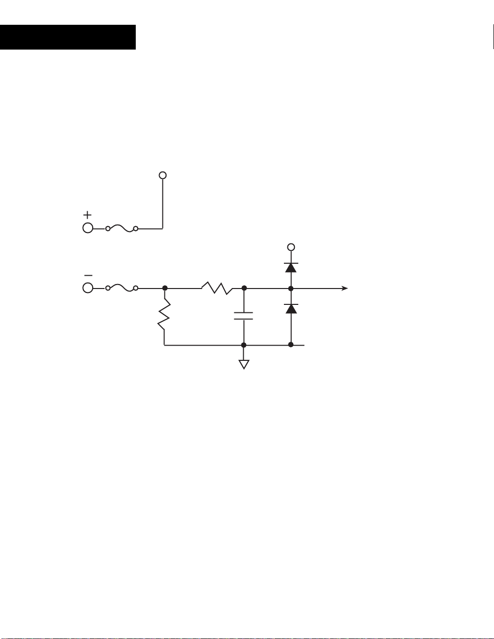
MI-6
Input Circ uitr y
The following is a simplif ied s c hem atic of the MI-6 Milliamp Input module:
24V
300mA
Resettable
Fuse
5V
100mA
Resettable
Fuse
249
R
Ω
C
To
Analog/Digital
Converter
All six input pairs include their own automatically r es ett able fuses. These devices are
designed to open when sensing an over-current. They reset when the current supplied is
within range.
Note: In some extreme instan ces, the fuses may require that you remove power to
the module temporari ly to reset their state.
56
Andover Controls
Page 63
Sensing Current
The current supplying sensor is c onnec ted as indicated in the following illustr ation:
Supply
MI-6
24V
Loop-Powered
Sensor
Signal
To measure current on an input , configure an input point with an Electr ic al Type of
Current
.
INx
Continuum I/O System Reference
57
Page 64

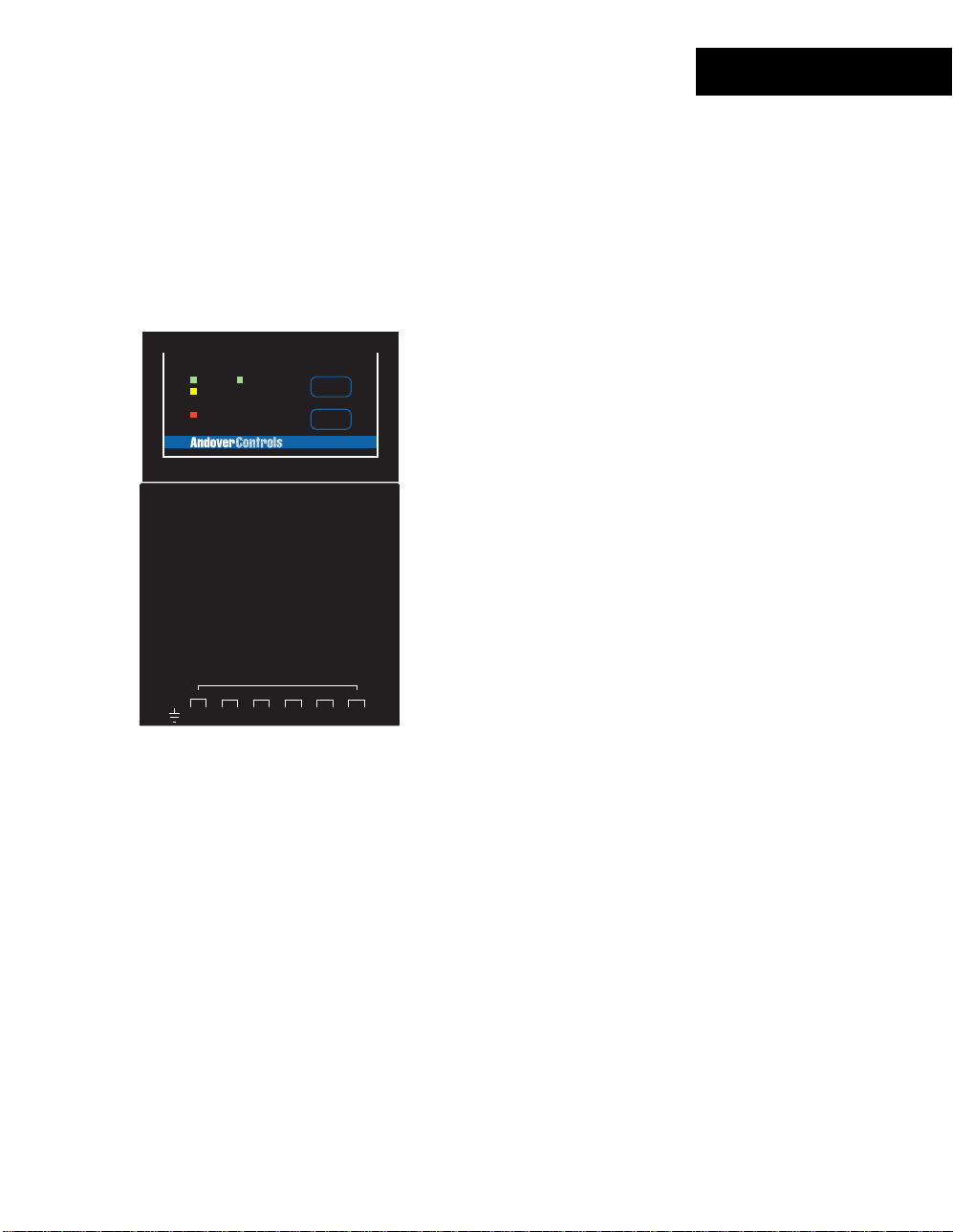
MI-6
Status/Control Pa nel
Status In dic a t or s
The MI-6 module includes a complete indicator status panel on t he front of the module.
POWER
COMM
STATUS
EXTERNAL
COMMISSION
RESET
MI-6
This panel includes indicator s r epor ting on the status of the following:
POWER
This green indicator illum inates when DC power is applied through the
Power/IO Bus.
COMM
This yellow indicator illum inates when data is transm itt ed from the
module to the NetCont r oller . In normal operation, data is only transm itted
when an input value changes.
This indicator will also flash periodically as the Net Controller checks the
I/O bus periodically.
STATUS
This red indicator is nor m ally off . If it is alway s on or flas hing at a fast
rate there is a problem with the module.
This indicator can be m anually illum inated from the Continuum
workstation and used as a troubleshooting aid when locating a part icular
module. More inform ation on using this indicator may be found in the
Troubleshooting
section of this manual.
EXTERNAL
58
Andover Controls
This green indicator illum inates when 24V DC power is available to
external sensors.
Page 65

This panel also includes two oper ator switches that perform the f ollowing:
MI-6
COMMISSION
RESET
After physic al installation and during configuration t hr ough the
Continuum workstation, pressing this butt on registers t he module’s
address with the syst em. For m or e information, refer to the section on
Configuring I/O
Should the module become inoperable, pr es s ing this button reset s the
module. It does not eras e its m emory.
found earlier in this manual.
Continuum I/O System Reference
59
Page 66

60
Andover Controls
Page 67

DM-20
The DM-20, Continuum’s Digit al Input and Output module, pr ov ides high dens ity,
versatile I/O for m any cont r ol applic ations. When coupled with the opt ional DIO-20
Expansion Board, t he DM - 20 allows you t o m ix and mat c h up to 20 digital inputs and
outputs. Using standar d off-the-shelf digital I/O blocks, the DIO-20 allows the syst em
designed to meet a wide range of applic ations, including ON-OFF or puls e- width
modulation (PWM) cont r ol of equipment and for switching inductive loads up to 240VAC.
The DM-20 provides 24 VDC power to the DIO- 20 v ia a separat e c able as s em bly .
When used without the DIO-20 E x pans ion B oar d, the DM-20 can control any combination
of inputs and output s, up to a total of 20 per module. The DM-20 can be used to
drive/sense up to 20 LEDs and/or switches on the Continuum enclosure’s door-mounted
GA-40 or GA-80 Graphic Annunciator Panel via an easy-to-use 25-pin cable assembly
and built-in terminal blocks.
FEATURES
READER
POWER
24VDC @ .36 Amps
+
TO DI0-20
V
+
-
12
12
POWER
COMM
STATUS
USE COPPER CONDUCTORS ONLY
USE COPPER CONDUCTORS ONLY
ON
OFF
AUTO
+ 5V, 100mA
+ 12V, 180mA
READER
G
DC
A
N
T
D
A
/
1
3
D CONNECTOR
I/O I/O I/O I/O I/O
I/O
I/O
SUPERVISED
14
15 16 17 18 19 20
INPUTS(0-5V)
1
23
L
E
D
L
A
R
O
D
K
U
E
O
X
X
R
/
0
I/O I/O I/O I/O I/O I/O I/O I/O
I/O
I/O
1
2 3 4 5 6 7 8 9 10 11 12 13
4
56
7
8
1-DOOR
CONTACT RATING:
24VAC/DC, 5A
1-DOOR
R
E
T
10 11 12
9
COMMISSION
RESET
DM-20
OUT 2
ON
OFF
AUTO
G
G
G
G
N
N
N
N
D
D
D
D
DIGITAL OUTPUTS
I/O
I/O I/O
13 14 15
20 General Purpose Digital Inputs/Outputs
•
Each point may be configured as an input or an
•
output
Direct connection to DIO-20 Expansion Module
•
Direct connection to GA-40/80 Graphic
•
Annunciator Panels.
G
N
D
OUT2
Continuum I/O System Reference
61
Page 68

DM-20
SPECIFICATIONS
ELECTRICAL
Power Consumption:
External Power Connector:
0.5 watt at 24VDC max; provided by Continuum power
supply module.
Up to 9 watts at 24VDC when the DIO-20 is powered from
the DM-20 .
Three-position removable connector
Overload Protection:
LED Power Supply:
INPUTS/OUTPUTS 20 total points; user-selectable channel-by-channel as
Inputs:
Input Type: w/DIO-20 w/o DIO-20
Pulse Width:
Outputs:
Output Type: w/DIO-20 w/o DIO-20
Output Resolution:
Output Protection:
I/O Connections:
0.5A resettable fuse with transient voltage suppressor
(TVS) and reverse polarity protection for both DM-20 power
and DIO-20 power.
Customer-provided external 5V power supply when using
the DM-20 to drive LEDs.
inputs or outputs
24 VDC logic voltage (DIO-20). 0-5 VDC
Input rating depends on input
module(s) selected.
125 ms min. 125 ms min.
5 VDC logic voltage. Open- collector Output
Range depends on output transistor with series
module selected. 330 ohm 1/8 W resistor;
5 VDC max., 15 mA
0.1 sec. For Pulse Width Modulation (PWM) control
Transient voltage suppressor (TVS) and current limiting
resistor on each channel.
25-position DB25 Female and one removable three-
terminal block.
62
Andover Controls
Page 69

DM-20
I/O Connecti ons
The actual I/O connect ions ar e loc ated on a 25-position DB25-type fem ale c onnec tor
located at the bottom of the module. A separate three-conductor removable screw
connector provides 24V DC power to external devices.
The inputs are labeled I/O 1, I/O2, I/O3, and so forth. Each input/ output occupies a single
position of the connec tor. Five signal ground pins are supplied as well.
The diagram below indicates wher e eac h input number is located on the module.
1 Shield/Earth Ground
2 + 24VDC @ .36 Amps
3 24 V Return
25-Pin D Connector
I/O 1
1.
I/O 2
2.
I/O 3
3.
I/O 4
4.
I/O 5
5.
I/O 6
6.
I/O 7
7.
I/O 8
8.
I/O 9
9.
10. I/O 10
11. I/O 11
12. I/O 12
13. I/O 13
14. I/O 14
15. I/O 15
16. I/O 16
17. I/O 17
18. I/O 18
19. I/O 19
20. I/O 20
21. Ground
22. Ground
23. Ground
24. Ground
25. Ground
READER
POWER
24VDC @ .36 Amps
+
TO DI0-20
V
+
-
12
12
POWER
COMM
STATUS
USE COPPER CONDUCTORS ONLY
USE COPPER CONDUCTORS ONLY
ON
OFF
AUTO
+ 5V, 100mA
+ 12V, 180mA
READER
G
DC
A
N
T
D
A
/
1
3
L
K
/
0
4
D CONNECTOR
I/O I/O I/O I/O I/O
I/O
I/O
SUPERVISED
14
15 16 17 18 19 20
INPUTS(0-5V)
1
23
L
E
D
A
R
O
D
U
E
O
X
X
R
I/O I/O I/O I/O I/O I/O I/O I/O
I/O
I/O
1
2 3 4 5 6 7 8 9 10 11 12 13
56
7
8
1-DOOR
CONTACT RATING:
G
24VAC/DC, 5A
N
DIGITAL OUTPUTS
1-DOOR
R
E
T
10 11 12
9
COMMISSION
RESET
DM-20
ON
OFF
AUTO
G
G
N
N
D
D
D
I/O
OUT 2
G
G
N
N
D
D
OUT2
I/O I/O
13 14 15
Continuum I/O System Reference
63
Page 70

DM-20
Input/Output Circuitr y
The following is a simplif ied s c hem atic of each DM-20 Input/Output channel:
I/O x
330
II
I/O Channel (same for all 20 channels)
24V
500mA
Resettable
Fuse
All 20 I/O channels resem ble the circuit shown above.
The 24VDC power available to external devices includes an autom atically resettable
fuse. This fuse is designed t o open when an ex ternal device tries to extract mor e c ur r ent
than is available. They r es et when t he c ur r ent draw is bac k within r ange.
Note: In some extreme instan ces, the fuses may require that you remove power to
the module temporari ly to reset their state.
64
Andover Controls
Page 71

DM-20
Using the DM-20
The DM-20 is primarily des igned to directly interface with t he DIO-20 or the G A-40 / GA80 Graphic Annunciator P anels . However, it can also be used as a general purpose
digital I/O module containing 20 points.
DIO-20 Interface
The DIO-20 Expansion Module pr ov ides a c onnec tion for up to 20 solid state input or
output modules for the I/O channels of the DM-20. It includes individually fused s oc k ets
for modules from manuf actur er s s uc h as Opto 22, Gr ay hill, Gordos, Crydom and Potter &
Brumfield. You c an mix input and output modules on the DIO-20 as needed.
The connection between the DM-20 and the DIO-20 consists of a 25-pin ribbon cable to
supply data between the m odules and a two-conductor power cable.
Data connection between the two is accomplished via a 25-pin male-m ale DB 25 c able:
DM-20
DM-20 to DIO-20
Data Connection
DIO-20
Continuum I/O System Reference
65
Page 72

DM-20
The Power connection between the DIO-20 and the DM-20 is via a two-conductor c able
assembly as shown:
DM-20
D CONNECTOR
G
G
G
G
G
N
N
N
N
N
D
D
D
D
D
I/O
I/O I/O
+24 V Return
DM-20 to DIO-20
DC Power Connection
DIO-20
24VDC @ .36 Amps
TO DI0-20
+
-
12
I/O I/OI/O I/O I/O
I/O
I/O
14
15 16 17 18 19 20
I/O I/O I/OI/O I/O I/O I/O I/O
I/O
I/O
1
2 3 4 5 6 7 8 9 10 11 12 13
+24 VDC
Using the DM-20/DIO- 20 Combination
The DIO-20 provides t he DM-20 wit h a r eal- wor ld interface to its I/O channels. Solid- s tate
input modules (on the DIO- 20) pr ov ide interface circuitry to a variety of signals . These
modules convert t heir s ignals to digital levels for input to the DM-20.
Similarly, solid-s tate output modules (on the DIO - 20) allow the digital levels of the DM-20
to interface to a var iety of signals .
In both cases, the I/O points are set up to have an Electrical Type of
Digital
no matter
what type of solid-st ate module is installed.
For more information on the DIO-20, refer to its User Manual.
66
Andover Controls
Page 73

DM-20
GA-40/ GA-80 Interface
The GA-40 and GA-80 Graphic A nnunc iator Panels provide the capability of creating
custom display and control panels attached to the Continuum NE M A enclosur e or to an
auxiliary panel. These panels pr ov ide a c onnec tion for up to 40 (GA-40) or 80 (GA-80)
input switches or output LEDs. You can mix the number of switches and LEDs as
needed.
The connection between the DM-20 and the GA-40 and GA-80 panels consist s of a 25pin ribbon cable to supply data between the modules and a three-c onduc tor power cable.
Data connection between the two is accomplished via a 25-pin male DB25 c able that is
permanently att ac hed to the GA panels.
The GA-40 provides inter faces for 2 DM-20 modules. The GA-80 provides interfaces for
up to 4 DM-20 modules.
DM-20
GA-40/80
DM-20 to GA-40/80
Data Connection
Continuum I/O System Reference
67
Page 74
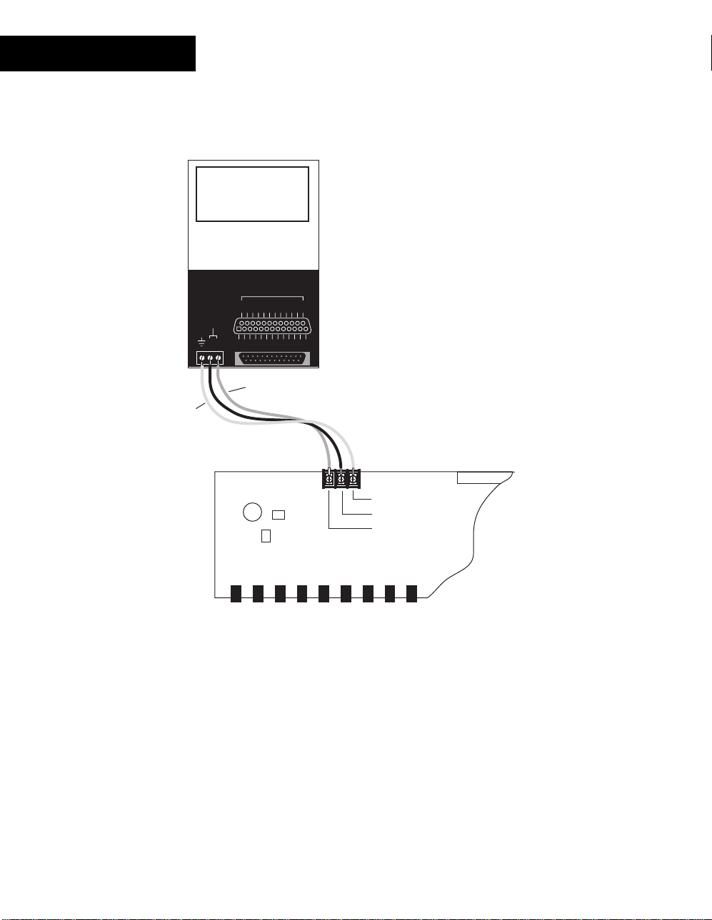
DM-20
The Power connection between the GA-40/80 modules and the DM-20 is via a threeconductor cable assem bly as s hown:
DM-20
D CONNECTOR
G
G
G
G
G
N
N
N
N
N
D
D
D
D
D
I/O
I/O I/O
DM-20 to GA-40/80
DC Power Connection
Chassis Gnd
24VDC @ .36 Amps
TO DI0-20
+
-
12
I/O I/OI/O I/O I/O
I/O
I/O
14
15 16 17 18 19 20
I/O I/OI/O I/O I/O I/O I/O I/O
I/O
I/O
1
2 3 4 5 6 7 8 9 10 11 12 13
+24 V Return
Chassis Ground
+24 VDC
24 V Return
GA-40/80
Using the DM-20/GA-40/ 80 Combination
The GA-40/80 series of modules pr ov ide the DM-20 with an easy to configure panel
interface to its I/O c hannels . Switches (connected to the GA- 40/80) provide user inputs to
the DM-20.
Similarly, LEDs ( c onnec ted to the GA-40/80) allow the digital levels of the DM-20 to
display a variety of conditions .
In both cases, the I/O points are set up to have an Electrical Type of
what type of device is installed.
For more information on the GA-40/80, refer to its section found in the
Module Reference
68
Andover Controls
Manual.
Digital
no matter
Continuum Display
Page 75
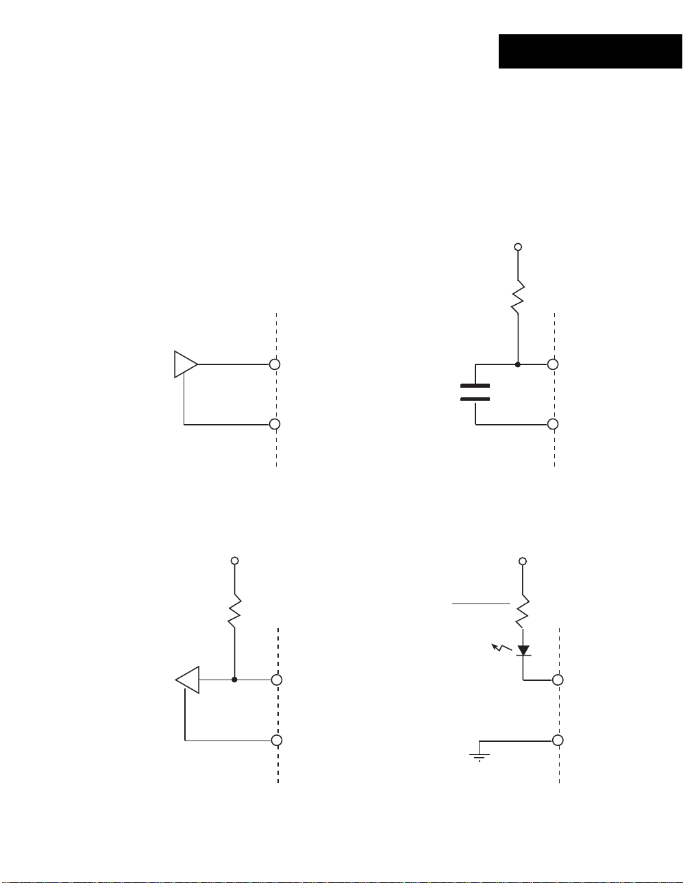
DM-20
General Purpose DM- 20 Digit al Int erf ace
The DM-20 can be used to provide 20 general pur pos e digital inputs and outputs. I t is not
necessary to int erfac e the module with an external expansion product to use its
capabilities. Each c hannel c an be us ed to output as digital signal or read a digit al s ignal
or contact closure. S et t he Elect r ic al Type to
Digital
The DM-20 can be configured as a general pur pos e digital input. With the addit ion of an
external referenc e pull- up r es is tor, it can be used for sensing cont act c los ur es as shown
below:
.
5V
10K
Digital logic
Signal
I/O x
GROUND
Contact
Closure
I/O x
GROUND
As a digital output, t he DM-20 pres ents an open collector load directly on the output
terminal. Connect digital devices and LED indicators as shown below:
Digital logic
Input
5V
10K
I/O x
GROUND
Resistor value determined
according to the
current requirements
of the LED
LED
Indicator
+V
I/O x
GROUND
Continuum I/O System Reference
69
Page 76

DM-20
Status/Control Pa nel
Status In dic a t or s
The DM-20 module includes a com plete indicator status panel on t he front of the module.
POWER
COMM
STATUS
COMMISSION
RESET
DM-20
This panel includes indicator s r epor ting on the status of the following:
POWER
This green indicator illum inates when DC power is applied through the
Power/IO Bus.
COMM
This yellow indicator illum inates when data is transm itt ed from the
module to the NetCont r oller . In normal operation, data is only transm itted
when an input value changes.
This indicator will also flash periodically as the Net Controller checks the
I/O bus periodically.
STATUS
This red indicator is nor m ally off . If it is alway s on or flas hing at a fast
rate there is a problem with the module.
This indicator can be m anually illum inated from the Continuum
workstation and used as a troubleshooting aid when locating a part icular
module. More inform ation on using this indicator may be found in the
Troubleshooting
section of this manual.
70
Andover Controls
Page 77

This panel also includes two oper ator switches that perform the f ollowing:
DM-20
COMMISSION
RESET
After physic al installation and during configuration t hr ough the
Continuum workstation, pressing this butt on registers t he module’s
address with the syst em. For m or e information, refer to the section on
Configuring I/O
Should the module become inoperable, pr es s ing this button reset s the
module. It does not eras e its m emory.
found earlier in this manual.
Continuum I/O System Reference
71
Page 78

72
Andover Controls
Page 79

AO-4-8
The AO-4-8, Continuum ’s analog output module, has four analog outputs with eight-bit
resolution, which can be c onfigured as either voltage ( 0- 10V DC) or cur r ent (0- 20m A )
outputs. The AO-4-8 is the perfect choice for valves, dampers, v ar iable s peed dr iv es , and
similar equipment that demand high control accurac y.
An AO-4-8-O model with full ov er r ide c apabilities is also available. Each output contains
a three-position manual ov er r ide s witch and override potentiom eter. In addition, the AO4-8-O provides soft war e ov er r ide feedback to Andover’s
language for each output.
FEATURES
Plain English
programming
POWER
COMM
OVERRIDE
STATUS
USE COPPER CONDUCTORS ONLY
USE COPPER CONDUCTORS ONLY
OUT1
MANUAL
MANUAL
OFF
OFF
AUTO
AUTO
ADJUST
READER
POWER
+ 5V, 100mA
CURRENT OUTPUT: 0 - 20mA, 650 OHMS MAX.
+ 12V, 180mA
VOLTAGE OUTPUT: 0 - 10V, 2K OHMS MIN.
READER
+
G
DC
A
N
V
L
OUT1
T
D
K
A
/
/
I
GND
V
1
0
123456789101112
4
12
3
OUT3 OUT4
OUT2
1-DOOR
MANUAL
ON
OFF
OFF
AUTO
AUTO
MANUAL
ADJUST ADJUST ADJUST
SUPERVISED
INPUTS(0-5V)
ANALOG OUTPUTS
1
23
L
E
D
OUT2
OUT3
R
A
R
O
D
E
U
E
O
T
X
X
R
I
I
GND
V
56
7
9
8
COMMISSION
RESET
AO-4
MANUAL
ON
OFF
OFF
AUTO
AUTO
CONTACT RATING:
DIGITAL OUTPUTS
1-DOOR
GND
V
10 11 12
OUT 2
OUT2
OUT4
I
13 14 15
4 Analog Outputs
•
8 bit Resolution
•
0-10V Voltage Out puts
•
0-20mA Current Outputs
•
AO-4-8-O Only:
Override Toggle Switches and Potentiometers
•
Override Detection
•
GND
V
Continuum I/O System Reference
73
Page 80

AO-4-8
SPECIFICATIONS
ELECTRICAL
Power Consumption:
3.8 watts at 24VDC max; normally provided by Continuum
power supply module.
Overload Protection:
OUTPUTS
AO-4-8:
AO-4-8-O:
Output Protection:
Output Connections:
Output Types:
Voltage:
Range:
Resolution:
Accuracy:
Output Current:
Load Resistance:
Curren t:
Range:
Resolution:
Accuracy:
0.5A resettable fuse with transient voltage suppressor
(TVS) and reverse polarity protection.
4 Analog outputs; 8 bit resolution
4 Analog outputs with overrides; 8 bit resolution
1/8 pico fuse per channel (40V TVS on each outputAO-4-
8-O model only)
Two-piece, 13-position removable terminal block
Voltage or current
0 to 10 V
0.05 V
±0.10V (1%FSR)
+5 mA (sourcing) -1 mA (sin k i n g)
2KΩ min.(sourcing)
0 to 20 mA
0.1 mA
±0.2 mA
Output Overrides: 3-position manual override switch and override
(AO-4-8-O only)
Output Connections: Two-piece, 13-position removable terminal block
74
Andover Controls
Load Resistance:
650Ω max.
potentiometer on each output, with software feedback. LED
override status indicator.
Page 81

AO-4-8
I/O Connecti ons
The actual output connections are located on a thirteen-position removable screw
terminal connector loc ated at the bottom of the module. Output wires s hould enter from
either the top or bott om wiring t r oughs , and should come from the right side of the rack
(by convention).
The outputs are labeled OUT 1 I, OUT 1 V, OUT1 GND, and so forth. Each output
presents two ways of connect ing, resulting in a current output of OUT1 I and OUT1 GND,
and a voltage output bet ween OUT1 V and OUT1 GND.
The diagram below indicates wher e eac h output number is located in the terminal bloc k .
Shield/Earth G r ound
OUT1 I
1.
OUT1 V
2.
OUT1 GND
3.
OUT2 I
4.
OUT2 V
5.
OUT2 GND
6.
OUT3 I
7.
OUT3 V
8.
OUT3 GND
9.
10. OUT4 I
11. OUT4 V
12. OUT4 GND
MANUAL
AUTO
POWER
COMM
OVERRIDE
STATUS
COMMISSION
RESET
AO-4
USE COPPER CONDUCTORS ONLY
USE COPPER CONDUCTORS ONLY
OUT1
OFF
OUT2
MANUAL
OFF
AUTO
OUT3 OUT4
1-DOOR
MANUAL
ON
OFF
OFF
AUTO
AUTO
MANUAL
ON
OFF
AUTO
AUTO
OUT 2
OFF
MANUAL
ADJUST
READER
POWER
+
V
I
123456789101112
12
ADJUST ADJUST ADJUST
+ 5V, 100mA
CURRENT OUTPUT: 0 - 20mA, 650 OHMS MAX.
+ 12V, 180mA
VOLTAGE OUTPUT: 0 - 10V, 2K OHMS MIN.
READER
G
N
OUT1
D
V
DC
A
T
A
/
GND
1
3
ANALOG OUTPUTS
L
E
L
OUT2
D
K
/
I
0
4
56
SUPERVISED
INPUTS(0-5V)
1
A
U
X
V
23
D
O
O
R
GND
7
R
R
E
E
T
X
I
9
8
CONTACT RATING:
DIGITAL OUTPUTS
1-DOOR
OUT3
GND
V
10 11 12
OUT2
OUT4
I
13 14 15
Continuum I/O System Reference
GND
V
75
Page 82
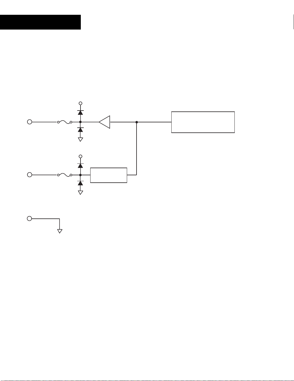
AO-4-8
Output Circuitry
The following is a simplif ied s c hem atic of each AO-4-8 Output channel:
24V
125mA
OUTx V
OUTx I
Resettable
Fuse
125mA
Resettable
Fuse
24V
Voltage to Current
Converter
Digital to Analog
Converter
GND
All 4 channels resemble the c ir c uit shown above.
The outputs include an automatically resettable fuse. This fuse is designed to open when
an external device tr ies to extract more current than is available. They reset when the
current draw is back within r ange.
Note: In some extreme instan ces, the fuses may require that you remove power to
the module temporari ly to reset their state.
76
Andover Controls
Page 83

AO-4-8
Override Control s
The AO-4-8-O model includes an out put override switch and manual variable
voltage control f or eac h output .
MANUAL
OFF
AUTO
ADJUST
The output of the module can be directed from program control to manual
control. The output c an be dis abled c om pletely as well.
The following describes the actions associat ed with each position of the override
controls:
MANUAL
OFF
AUTO
ADJUST
The analog signal generated by t he m odule is c ontrolled
manually by adjusting the A DJ US T pot entiometer below to the
manual override switch. Programs have no effect on the output
when the switch is in this position.
The output is disconnect ed. Programs and the setting on the
ADJUST potentiomet er hav e no eff ec t on t he output Dev ic e
when the switch is in this position.
The analog signal is generated as a dir ec t result of program
control. The setting on the ADJUST potentiometer has no effec t
on the output Device when the switch is in this position.
This is a variable cont r ol that allows y ou to manually adjus t the
output of the analog signal when the ov er r ide s witch is in the
MANUAL position. Insert the tip of a small screwdriver to use this
control. Tur ning to the right (clockwise) increases the out put.
Turning left (c ounterclockwise) decreases t he output.
Continuum I/O System Reference
77
Page 84

AO-4-8
Voltage Output
The voltage output is a ground-r eferenced signal with a range of 0- 10V DC. The
maximum output current is 5mA (2,000 ohms minimum resistance) . Ens ur e that the
device being connected is eit her floating or at the same ground potential as the controller.
Configure the output point with an Electrical Type of
Voltage
.
Connect the device acr os s the following terminals:
OUTx I
OUTx V
Device
Load
Resistance
≥ 2K
Ω
GND
Note: The load resistanc e ( of t he exter nal dev ic e) m us t be greater than or equal to 2 K
.
Ω
78
Andover Controls
Page 85

Current Output
The current output is a current-sourcing, ground referenc ed c ir c uit. This output can
source 0 - 20 mA with a maximum load impedance of 650 ohms .
AO-4-8
Configure the output point with an Electrical Type of
Current
.
Connect the device acr os s the following terminals:
OUTx I
Device
Load
Resistance
≤ 650
Ω
OUTx V
GND
Note: The load resistanc e ( of t he exter nal dev ic e) m us t be less than or equal to 650
.
Ω
Continuum I/O System Reference
79
Page 86

AO-4-8
Status/Control Pa nel
Status In dic a t or s
The AO-4-8 module includes a com plete indicator status panel on t he front of the module.
POWER
COMM
OVERRIDE
STATUS
COMMISSION
RESET
AO-4
This panel includes indicator s r epor ting on the status of the following:
POWER
This green indicator illum inates when DC power is applied through the
Power/IO Bus.
COMM
This yellow indicator illum inates when data is transm itt ed from the
module to the NetCont r oller . In normal operation, data is only transm itted
when an input value changes.
This indicator will also flash periodically as the Net Controller checks the
I/O bus periodically.
STATUS
This red indicator is nor m ally off . If it is alway s on or flas hing at a fast
rate there is a problem with the module.
This indicator can be m anually illum inated from the Continuum
workstation and used as a troubleshooting aid when locating a part icular
module. More inform ation on using this indicator may be found in the
Troubleshooting
section of this manual.
OVERRIDE
80
Andover Controls
This red indicator illum inates whenever any of the override s witches is in
a position other than A UTO.
Page 87

This panel also includes two oper ator switches that perform the f ollowing:
AO-4-8
COMMISSION
RESET
After physic al installation and during configuration t hr ough the
Continuum workstation, pressing this butt on registers t he module’s
address with the syst em. For m or e information, refer to the section on
Configuring I/O
Should the module become inoperable, pr es s ing this button reset s the
module. It does not eras e its m emory.
found earlier in this manual.
Continuum I/O System Reference
81
Page 88

82
Andover Controls
Page 89
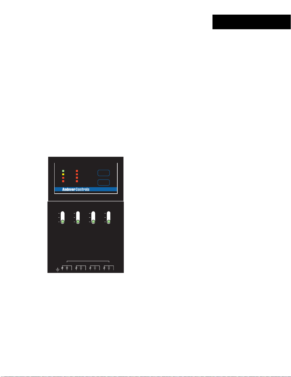
DO-4-R
The DO-4-R, Continuum’s digital output module, has four Form C relay outputs, rated at
5 amps, 240 VAC. These versatile out puts make the DO-4-R an excellent choic e for
switching motor star ters and other inductive loads up t o 240 VAC, with either two position
(on/off) or pulse-width modulation (PWM) cont r ol. T he PWM featur e per m its the
modulation of valves and dam per s to 0.1 second resolution. Two adjacent Form C relay
outputs can be combined in s oft war e to provide a Tri-state output, for bi- dir ec tional
control of valves and dam per s and other end dev ic es . Metal oxide varistors and 5000V
isolation on each output ens ur e r eliable nois e- free operation.
A DO-4-R-O model with full over r ide c apabilities is also available. Each output has a local
hand-off-auto s witch, which enables service personnel to override the output. The switch
also provides override f eedbac k of output values for use in troubleshooting or test
conditions. A local indic ator light for each output dis play s r elay status. Another LED
provides override st atus.
FEATURES
POWER
COMM
OVERRIDE
STATUS
OUTPUT
1
2
3
4
COMMISSION
RESET
DO-4
4 Form C Relay Outputs
•
240 VAC @ 5A Contact Rating
•
Output Status LEDs
•
USE COPPER CONDUCTORS ONLY
USE COPPER CONDUCTORS ONLY
OUT1
ON
ON
OFF
OFF
AUTO
AUTO
WARNING:
AVERTISSEMENT:
CAUTION:
HIGH VOLTAGE INSIDE-DANGEROUS TO
UNQUALIFIED PERSONS.
READER
POWER
MORE THAN ONE DISCONNECT MAY BE
REQUIRED TO DE-ENERGIZE THIS EQUIPMENT.
+ 5V, 100mA
CONTACT RATING: 240 VAC, 5A
+ 12V, 180mA
30 VDC, 5A
READER
+
G
DC
A
N
V
L
T
D
OUT1
K
A
/
1
0
123456789101112
4
12
3
OUT3
OUT2
1-DOOR
ON
ON
OFF
OFF
AUTO
AUTO
HAUTE TENSION A L'INTERIEUR-DANGER
POUR LES PERSONNES NON-QUALIFIER.
SUPERVISED
INPUTS(0-5V)
DIGITAL OUTPUTS
1
23
L
E
D
R
A
R
O
D
OUT2 OUT3
E
U
E
O
T
X
X
R
/
56
7
10 11 12
9
8
OUT4
OUT 2
ON
ON
OFF
OFF
AUTO
AUTO
CONTACT RATING:
24VAC/DC, 5A
DIGITAL OUTPUTS
1-DOOR
13 14 15
DO-4-R-O Only:
Override Toggle Switches
•
Override Detection
•
OUT2
OUT4
Continuum I/O System Reference
83
Page 90

DO-4-R
SPECIFICATIONS
ELECTRICAL
Power Consumption:
2.8 watts at 24VDC max; normally provided by Continuum
power supply module.
Overload Protection:
OUTPUTS
DO-4-R:
DO-4-R-O:
Output Rating:
Output Resolution:
Output Protection:
Output Overrides:
Override Feedback:
Output Connections:
0.5A resettable fuse with transient voltage suppressor
(TVS) and reverse polarity protection.
4 Form C relay outputs
4 Form C relay outputs with overrides
240 VAC, 5 amps; 30 VDC, 5 amps
0.1 sec. For Pulse Width Modulation (PWM) control
270 Volt varistors across contacts.
5000 VRMS isolation @ 60 Hz between relay contacts and
relay coil.
3-position manual override switch on each output, with
software feedback.
LED override status indicator (DO-4-R-O only)
Override detection and feedback provided for each output.
Two-piece, 13-position removable terminal block
84
Andover Controls
Page 91

DO-4-R
I/O Connecti ons
The actual output connections are located on a thirteen-position removable screw
terminal connector loc ated at the bottom of the module. Output wires s hould enter from
either the top or bott om wiring t r oughs , and should come from the right side of the rack
(by convention).
The outputs are labeled OUT 1 NC, OUT 1 NO, OUT 1 COM, and so forth. Each out put
presents a single pole double thr ow s et of contacts. OUT 1 NC is the normally closed
side of the contact. O UT 1 NO is the normally open c ontact. OUT 1 COM is the common
connection that r epr es ents the armature of the relay switch.
The diagram below indicates wher e eac h output number is located in the terminal bloc k .
Shield/Earth G r ound
1. OUT 1 NC
2. OUT 1 NO
3. OUT 1 COM
4. OUT 2 NC
5. OUT 2 NO
6. OUT 2 COM
7. OUT 3 NC
8. OUT 3 NO
9. OUT 3 COM
10. OUT 4 NC
11. OUT 4 NO
12. OUT 4 COM
OUT1
ON
OFF
AUTO
WARNING:
AVERTISSEMENT:
READER
POWER
CAUTION:
+
V
123456789101112
12
OUTPUT
POWER
COMM
OVERRIDE
STATUS
+ 5V, 100mA
+ 12V, 180mA
READER
G
N
D
OUT1
1
2
3
4
USE COPPER CONDUCTORS ONLY
USE COPPER CONDUCTORS ONLY
OUT2
ON
OFF
AUTO
HIGH VOLTAGE INSIDE-DANGEROUS TO
UNQUALIFIED PERSONS.
MORE THAN ONE DISCONNECT MAY BE
REQUIRED TO DE-ENERGIZE THIS EQUIPMENT.
CONTACT RATING: 240 VAC, 5A
30 VDC, 5A
L
DC
A
E
L
T
D
K
A
/
/
1
0
4
56
3
OUT3
1-DOOR
ON
ON
OFF
OFF
AUTO
AUTO
HAUTE TENSION A L'INTERIEUR-DANGER
POUR LES PERSONNES NON-QUALIFIER.
CONTACT RATING:
23
D
O
O
R
7
R
E
X
8
24VAC/DC, 5A
DIGITAL OUTPUTS
1-DOOR
R
E
T
10 11 12
9
SUPERVISED
INPUTS(0-5V)
DIGITAL OUTPUTS
1
A
OUT2 OUT3
U
X
COMMISSION
RESET
DO-4
ON
ON
OFF
OFF
AUTO
AUTO
13 14 15
OUT4
OUT 2
OUT2
OUT4
Continuum I/O System Reference
85
Page 92

DO-4-R
Output Circuitry
The following is a simplif ied s c hem atic of each DO-4-R Output channel:
OUT x NC
OUT x NO
OUT x COM
All 4 channels resemble the c ir c uit shown above.
These output contacts operate as a standard relay. When the output is set to an ‘ON’
state, the normally open c ontacts (OUTx NO) close and the normally closed contacts
(OUTx NC) open.
To use the Form C output in your system, c onfigure an output point with an Electric al
Type of
86
Digital
Andover Controls
.
Page 93

DO-4-R
Override Control s
The DO-4-R-O model includes an output override switch for each output.
ON
OFF
AUTO
The output of the module can be directed from program control to manual
control. The output c an be dis abled c om pletely as well.
The following describes the actions associat ed with each position of the override
controls:
ON
OFF
AUTO
The output relay is energized to an ‘ON’ state manually by
setting the switch to ON. Programs have no effect on the output
when the switch is in this position.
The output relay is de-energiz ed to an ‘OFF’ state manually by
setting the switch to OFF. Programs have no effect on the output
when the switch is in this position.
The action of the output relay is determined as a direct result of
program control.
Continuum I/O System Reference
87
Page 94
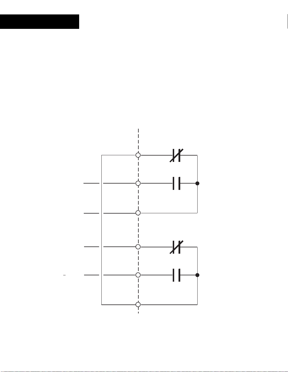
DO-4-R
Tri-State Output
Although the module cont ains four separate form C relays, adjacent pair s (OUT1 and
OUT2 or OUT3 and OUT4) of these can be combined t o form a st andar d Tri- s tate output.
Configure the output point of the first point (OUT1 or OUT3) with an Electr ic al Type of
Tri-state
Connect the two out puts toget her as follows:
.
OUT 1 NC
+ ON
Common
OFF
ON
OUT 1 NO
OUT 1 COM
OUT 2 NC
OUT 2 NO
OUT 2 COM
88
Andover Controls
Page 95
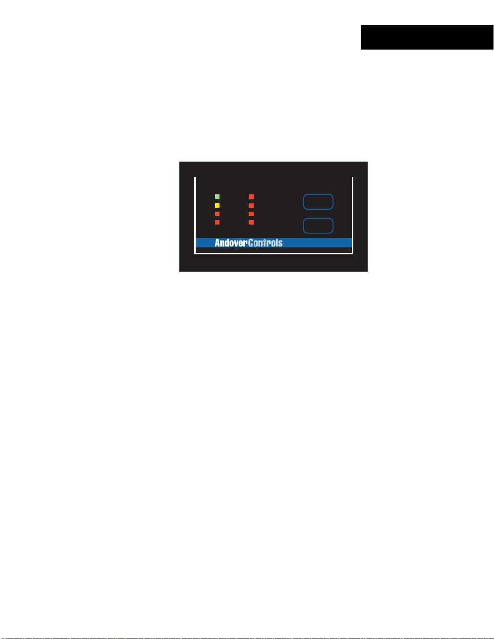
Status/Control Pa nel
Status In dic a t or s
The DO-4-R module includes a complete indicator status panel on t he front of the
module.
OUTPUT
POWER
COMM
OVERRIDE
STATUS
This panel includes indicator s r epor ting on the status of the following:
1
2
3
4
COMMISSION
RESET
DO-4
DO-4-R
POWER
COMM
OVERRIDE
STATUS
OUTPUT
This green indicator illum inates when DC power is applied through the
Power/IO Bus.
This yellow indicator illum inates when data is transm itt ed from the
module to the NetCont r oller . In normal operation, data is only transm itted
when an input value changes.
This indicator will also flash periodically as the Net Controller checks the
I/O bus periodically.
This red indicator illum inates whenever any of the override s witches is in
a position other than A UTO.
This red indicator is nor m ally off . If it is alway s on or flas hing at a fast
rate there is a problem with the module.
This indicator can be m anually illum inated from the Continuum
workstation and used as a troubleshooting aid when locating a part icular
module. More inform ation on using this indicator may be found in the
Troubleshooting
section of this manual.
These red indicators ( one for eac h c hannel) illum inate when an ‘ON’
condition is set.
Continuum I/O System Reference
89
Page 96

DO-4-R
This panel also includes two oper ator switches that perform the f ollowing:
COMMISSION
RESET
After physic al installation and during configuration t hr ough the
Continuum workstation, pressing this butt on registers t he module’s
address with the syst em. For m or e information, refer to the section on
Configuring I/O
Should the module become inoperable, pr es s ing this button reset s the
module. It does not eras e its m emory.
found earlier in this manual.
90
Andover Controls
Page 97

DO-6-TR
The DO-6-TR, Continuum’s triac output module, has six Form A triac - bas ed outputs,
rated at 0.5 amps, 24 VAC, for cost-effective on/off or pulse- width modulation (PWM)
control of lighting, heat, and fan units. The PWM feature perm its the modulation of valves
and dampers to 0.1 second resolution. Adjacent outputs can also be configured in pairs
to provide up to three Form K, Tri-s tate outputs for bi-direct ional c ontrol of dampers and
valves.
Metal oxide varist or s and optocouplers on the DO-6-TR provide 2500V is olation on each
output, ensure nois e- free operation, and, in most cases , eliminate the need to install
MOVs in the field.
FEATURES
OUTPUT
OUTPUT
1
POWER
COMM
STATUS
USE COPPER CONDUCTORS ONLY
USE COPPER CONDUCTORS ONLY
5
2
3
4
COMMISSION
6
RESET
DO-6
1-DOOR
ON
OFF
AUTO
OUT 2
ON
OFF
AUTO
Six (6) Triac-based out puts
•
24 Vrms @ 5A Contact Rating
•
Output Status LEDs
•
READER
POWER
+ 5V, 100mA
OUTPUT RATING: 24 VAC, 0.5A
+ 12V, 180mA
SUPERVISED
INPUTS(0-5V)
READER
DIGITAL OUTPUTS
1
DC
A
T
A
/
1
3
23
L
E
D
L
A
O
D
OUT3
OUT2
K
U
O
X
R
/
0
4
56
7
+
G
N
V
D
OUT1
12345678
12
R
E
X
8
CONTACT RATING:
DIGITAL OUTPUTS
1-DOOR
R
OUT4
E
T
10 11 12
9
OUT5
910
OUT2
11 12
13 14 15
OUT6
Continuum I/O System Reference
91
Page 98

DO-6-TR
SPECIFICATIONS
ELECTRICAL
Power Consumption:
1.1 watts at 24VDC max; normally provided by Continuum
power supply module.
Overload Protection:
OUTPUTS
Output Type:
Output Rating:
Output Accuracy:
Output Protection:
Output Connections:
0.5A resettable fuse with transient voltage suppressor
(TVS) and reverse polarity protection.
6 Form A optically isolated triac outputs (can be configured
up to 3 Form K Tri-State outputs)
0.5A, 24 VAC, (Cannot switch DC loads)
0.1 sec. for Pulse Width Modulation (PWM) control
2500V optical isolation
Metal oxide varistor and snubber on each output
Two-piece, 13-position removable terminal block
92
Andover Controls
Page 99
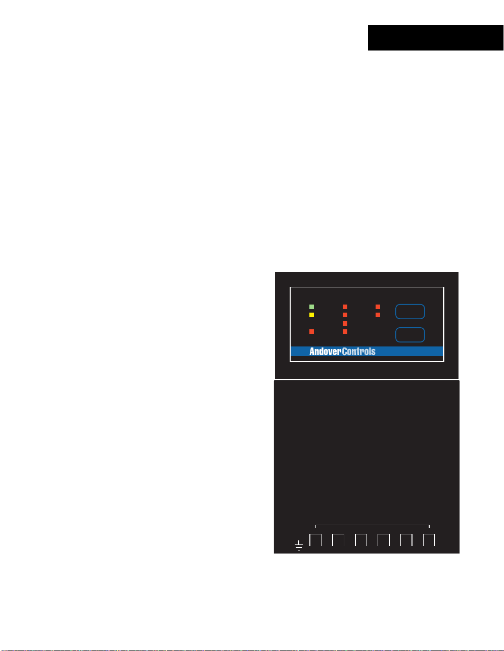
DO-6-TR
I/O Connecti ons
The actual output connections are located on a thirteen-position removable screw
terminal connector loc ated at the bottom of the module. Output wires s hould enter from
either the top or bott om wiring t r oughs , and should come from the right side of the rack
(by convention).
The outputs are grouped in pairs of two connector terminals per channel. Each output
presents a normally open s ingle pole s et of contacts.
The diagram below indicates wher e eac h output number is located in the terminal bloc k .
Shield/Earth G r ound
1. OUT 1
2. OUT 1
3. OUT 2
4. OUT 2
5. OUT 3
6. OUT 3
7. OUT 4
8. OUT 4
9. OUT 5
10. OUT 5
11. OUT 6
12. OUT 6
OUTPUT
POWER
COMM
STATUS
USE COPPER CONDUCTORS ONLY
USE COPPER CONDUCTORS ONLY
OUTPUT
1
2
3
4
5
6
COMMISSION
RESET
DO-6
1-DOOR
ON
OFF
AUTO
OUT 2
ON
OFF
AUTO
READER
POWER
+ 5V, 100mA
OUTPUT RATING: 24 VAC, 0.5A
+ 12V, 180mA
READER
+
G
N
V
D
OUT1
12345678
12
DC
A
L
T
OUT2
K
A
/
1
0
4
3
/
L
E
D
56
SUPERVISED
INPUTS(0-5V)
DIGITAL OUTPUTS
1
A
OUT3
U
X
23
D
R
O
E
O
X
R
7
8
CONTACT RATING:
DIGITAL OUTPUTS
1-DOOR
R
OUT4
E
T
10 11 12
9
OUT5
910
13 14 15
OUT2
11 12
OUT6
Continuum I/O System Reference
93
Page 100

DO-6-TR
Output Circuitry
The following is a simplif ied s c hem atic of each DO-6-TR Output channel:
OUT x
OUT x
All 6 channels resemble the c ir c uit shown above.
These output contacts operate as a solid state relay. When the out put is s et t o an ‘ON’
state, the cont acts c los e allowing current to flow between the output term inals .
To use the Form A output in your system, configure an output point with an Electrical
Type of
94
Digital
Andover Controls
.
 Loading...