

Page 1

For version v01.02.11
Page 2

2
Page 3

PROGRAMMER'S GUIDE FOR v01.02.11
Table of contents
1 INTRODUCTION......................................................................................................................................................................... 5
1.1 References .......................................................................................................................................................................... 5
1.2 Notices ................................................................................................................................................................................ 5
2 CONTROLING MIDRA™ ............................................................................................................................................................. 6
2.1 Introduction ........................................................................................................................................................................ 6
2.2 Physical interfaces ............................................................................................................................................................... 6
2.3 Protocol ............................................................................................................................................................................... 6
2.4 Command principle and structure ...................................................................................................................................... 7
2.4.1 Midra™ control principle ................................................................................................................................................. 7
2.4.2 Write command structure ............................................................................................................................................... 7
2.4.3 Read command structure ................................................................................................................................................ 7
2.4.4 Valid answer structure ..................................................................................................................................................... 8
2.4.5 Error answer .................................................................................................................................................................... 9
2.5 Commands sequencing ..................................................................................................................................................... 10
2.5.1 Write sequence .............................................................................................................................................................. 10
2.5.2 Read sequence ............................................................................................................................................................... 10
2.6 Command indexes and Command values ......................................................................................................................... 11
2.7 Multiple controllers........................................................................................................................................................... 12
2.8 Multiple machines ............................................................................................................................................................. 12
3 COMMON MIDRA™ USE CASES .............................................................................................................................................. 13
3.1 Establishing a connection with a Midra™ ......................................................................................................................... 14
3.1.1 usage .............................................................................................................................................................................. 14
3.1.2 summary of the commands sequence ........................................................................................................................... 14
3.1.3 detailed commands sequence ....................................................................................................................................... 14
3.1.4 example of connection establishment .......................................................................................................................... 16
3.2 Keeping a connection alive with a Midra™ ....................................................................................................................... 17
3.2.1 usage .............................................................................................................................................................................. 17
3.2.2 detailed command sequence ......................................................................................................................................... 17
3.2.3 example of PING command ........................................................................................................................................... 17
3.3 Changing a source displayed in a layer ............................................................................................................................. 18
3.3.1 usage .............................................................................................................................................................................. 18
3.3.2 Midra™ layers reminder ................................................................................................................................................ 18
3.3.3 detailed command parameters ..................................................................................................................................... 18
3.3.4 example of Preview layer source change ...................................................................................................................... 18
3.4 TAKE : Transitioning a Preview screen onto a Program screen ......................................................................................... 19
3.4.1 usage .............................................................................................................................................................................. 19
3.4.2 Midra™ transitions reminder ......................................................................................................................................... 19
3.4.3 detailed commands sequence ....................................................................................................................................... 19
3.4.4 example of TAKE ............................................................................................................................................................ 19
3.5 TAKE ALL : Transitioning from Preview onto the Program for all screens (matrix mode) ................................................ 20
3.5.1 usage .............................................................................................................................................................................. 20
3.5.2 Midra™ transitions reminder ......................................................................................................................................... 20
3.5.3 detailed commands sequence ....................................................................................................................................... 20
3.5.4 example of TAKE ALL...................................................................................................................................................... 20
3.6 Loading a Preset from Master memory to a single Program screen ................................................................................. 21
3.6.1 usage .............................................................................................................................................................................. 21
3.6.2 Midra™ “Master preset Memories” reminder .............................................................................................................. 21
3.6.3 detailed command parameters ..................................................................................................................................... 21
3.6.4 example of memorized preset recall ............................................................................................................................. 22
3.7 Loading a Preset from Master memory and changing the source displayed in a layer .................................................... 23
3.7.1 usage .............................................................................................................................................................................. 23
3.7.2 detailed commands sequence ....................................................................................................................................... 23
3.7.3 example of Master Memory preset recall ..................................................................................................................... 24
3.8 Displaying/Hiding the Quick Frame for one single screen ................................................................................................ 25
3.8.1 usage .............................................................................................................................................................................. 25
3
Page 4

3.8.2 detailed command sequence ......................................................................................................................................... 25
3.9 Displaying/Hiding the Quick Frames for all screens (matrix mode) .................................................................................. 25
3.9.1 usage .............................................................................................................................................................................. 25
3.9.2 detailed command sequence ......................................................................................................................................... 25
4 NOTES ..................................................................................................................................................................................... 26
4.1 Using this document ......................................................................................................................................................... 26
Pictures index
Picture 1 : RJ45 leds colors definition ....................................................................................................................................................... 6
Picture 2 : write command example ......................................................................................................................................................... 7
Picture 3 : read command example .......................................................................................................................................................... 8
Picture 4 : valid answer structure ............................................................................................................................................................. 8
Picture 5 : error answer example .............................................................................................................................................................. 9
Picture 6 : write command sequence ..................................................................................................................................................... 10
Picture 7 : read command sequence ...................................................................................................................................................... 10
Picture 8 : example of connection establishment .................................................................................................................................. 16
Picture 9 : example of keeping a connection alive ................................................................................................................................. 17
Picture 10 : Changing layer source - RCS² ............................................................................................................................................... 18
Picture 11 : example of Preview layer source change ............................................................................................................................ 18
Picture 12 : example of TAKE .................................................................................................................................................................. 19
Picture 13 : example of TAKE ALL............................................................................................................................................................ 20
Picture 14 : Loading Preset from memory - RCS² .................................................................................................................................... 21
Picture 15 : example of memorized preset recall ................................................................................................................................... 22
Picture 16 : example of Master Memory preset recall ........................................................................................................................... 24
Picture 17 : PDF reader, Previous and Next page buttons ...................................................................................................................... 26
4
Page 5

PROGRAMMER'S GUIDE FOR v01.02.11
1 INTRODUCTION
This document provides information and guidance to control Midra™ products directly from controllers
without using the standard RCS². A basic knowledge of the machine is necessary, using the RCS².
TPP stands for Third Party Protocol.
1.1 References
Midra_TPP_commands_for_v01-02-11.xls Midra™ v01.02.11 TPP command set
Midra™ v01.02.11 firmware updater (on ANALOG WAY web site)
EIKOS2 reference manual (on ANALOG WAY web site)
EIKOS2 quick start guide (on ANALOG WAY web site)
1.2 Notices
Pictures and drawings are non-contractual.
Specifications are subject to change without prior notice.
5
Page 6
PROGRAMMER'S GUIDE FOR v01.02.11
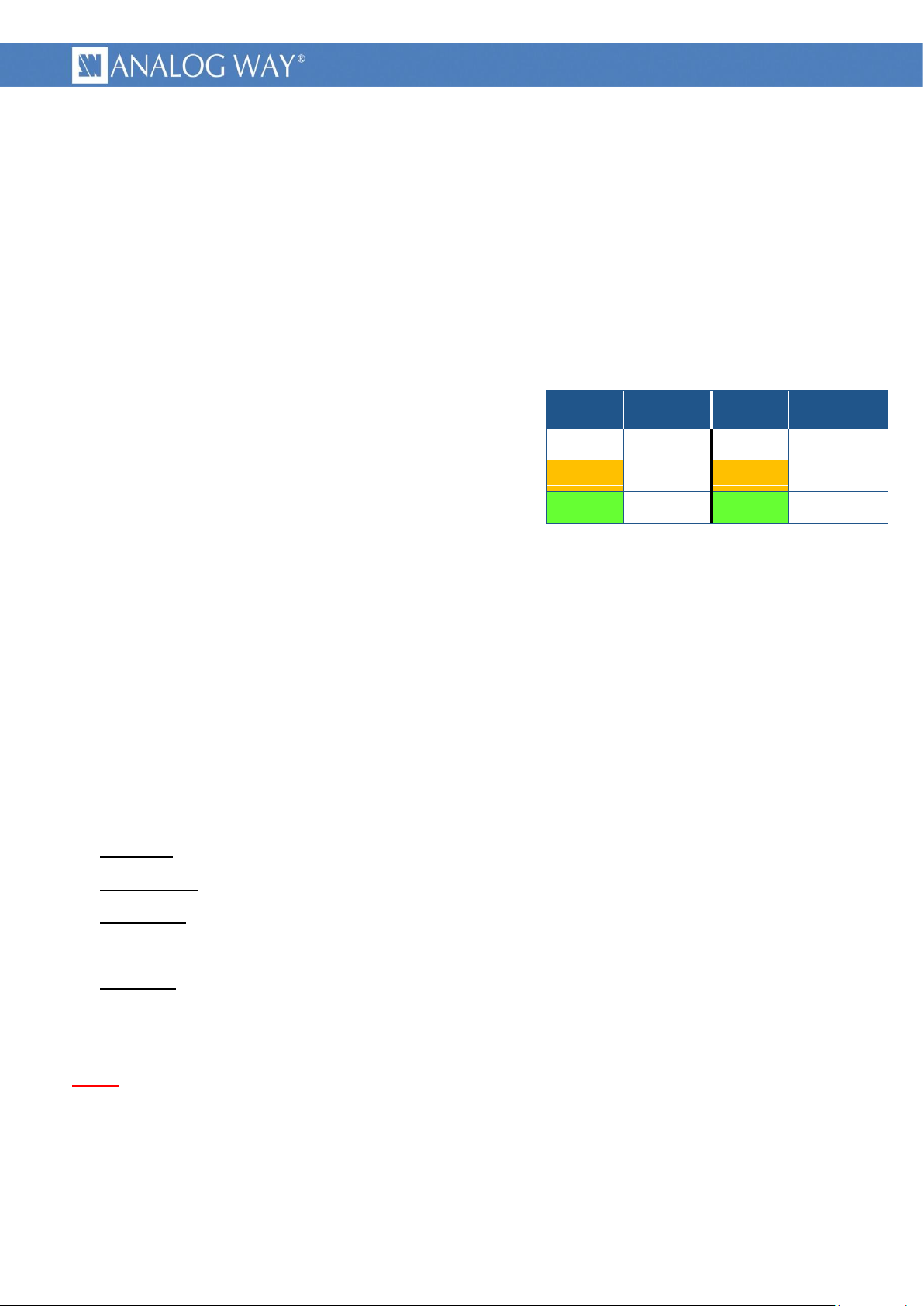
2 CONTROLING MIDRA™
Left LED
color
Definition
Right LED
color
Definition
Off
No link
Off
No activity
Amber
10 Mbps
Amber
Half-Duplex
Green
100 Mbps
Green
Full-Duplex
2.1 Introduction
Midra™ products are usually controlled by the user friendly RCS² or other high-end remote controller,
but a programming interface is also provided for automation applications.
A good practice is to setup the machine with the RCS² and then control it with a few basic commands
like “preset recalling” and “layer input change”.
2.2 Physical interfaces
Picture 1 : RJ45 leds colors definition
Midra™ can be controlled through its rear Ethernet RJ45
plug :
labeled “ETHERNET”
10Base-T or 100Base-TX (Auto-Sensing)
MDI connection (which need a crossover cable to
connect it directly to a computer)
Midra™ can also be controlled through its rear RS232 DB9 female plug :
labeled “RS-232”
1200Bds up to 115200 Bauds
3 wires straight cable, 8 data bits, 1 stop bit, no parity bit, no flow.
2.3 Protocol
Supported protocol is TCP/IP, parameters can be set up with front panel or RCS² configuration menus.
Default values are :
Protocol : TCP or UDP
DHCP client : no
IP address : 192.168.2.140
IP mask : 255.255.255.0
Gateway : 192.168.2.1
TPP port : 10500
6
Note : the simultaneous connection number is limited to 1.
Page 7
PROGRAMMER'S GUIDE FOR v01.02.11
2.4 Command principle and structure
2.4.1 Midra™ control principle
Midra™ functionalities are controlled through commands. Those commands allow reading or writing in
machine registers.
The product should be considered as a state machine controlled by writing to its registers. Writing into
registers modifies machine state. Current state of the machine is always available by reading its registers.
Registers structure and size can range from a simple bit up to multidimensional array of 32 bits words.
As a result, writing in such a multidimensional register requires providing indexes values in addition to the
register value.
Each register have a unique name, only made of five letters, upper case or lower case. (2 exceptions, 1
letter name command)
A command is made only of displayable ASCII characters (ranging from 0x21 up to 0x7E).
Commands are of 2 types : read commands or write commands, using the same syntax.
a write command is made of indexes values, followed by the register value and ended by the register
name.
a read command uses exactly the same syntax, except the register value that is omitted.
2.4.2 Write command structure
A write command is made of numeric values separated by comma, followed by a group of up to 5
letters defining the command.
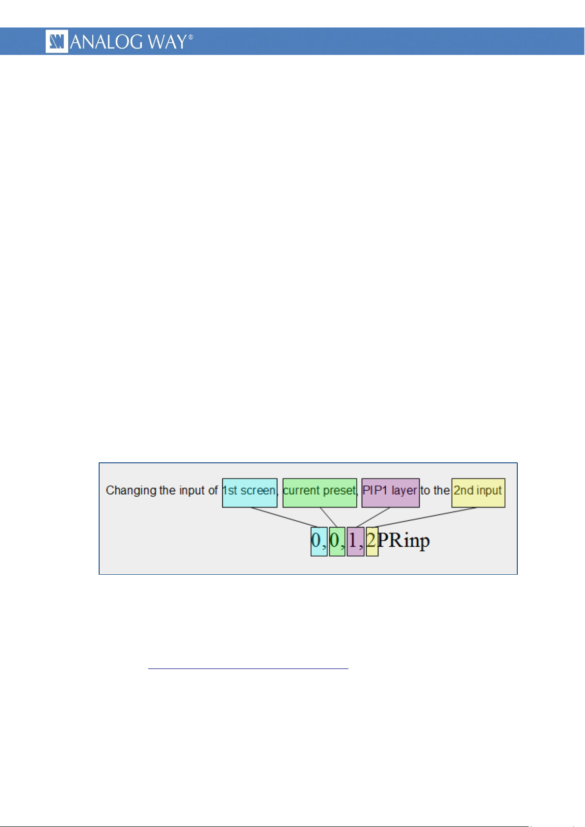
Picture 2 : write command example
The last numerical field is the value to be set by the write command.
The first numerical fields are “indexes values”, specifying on which the command relates. The number
of indexes can range from 0 to 5 depending on the command.
(details in chapter §Command indexes and Command values)
Each command is ended with the last command character.
2.4.3 Read command structure
A read command follows the same structure than the write command, simply with the value field
omitted. Please note that an index value is always followed by a comma character.
7
Page 8

PROGRAMMER'S GUIDE FOR v01.02.11
Picture 3 : read command example
2.4.4 Valid answer structure
When a read or write command is valid, the machine answers, giving the current register value. The
answer structure is symmetrical with the write or read command.
An answer is made of a group of letters (most often the same as the command) followed by numeric
C
values separated by comma, and is ended with
Picture 4 : valid answer structure
L
characters. (ASCII 0x0D and 0x0A)
R
F
An answer starts generally by the same group of letters than in the initial read or write command,
C
followed by indexes values, then command value and ending with
L
characters.
R
F
8
Page 9

PROGRAMMER'S GUIDE FOR v01.02.11
2.4.5 Error answer
When an invalid read or write command string is received, the machine ignores it, answers with the
previous value (unless in case of command error) and immediately answers with one of the following error
string.
Picture 5 : error answer example
Error message structure :
An error message is made of the capital letter E followed by a 2 digits value depending on the error and
C
is ended with
L
characters. (ASCII 0x0D and 0x0A)
R
F
Here are returned error code and conditions covered :
E10 : means “command name error”. It is usually due to a command field (i.e. five letters) that
does not match any legal command string.
E11 : means “index value out of range”. It is usually due to a wrong index value.
E12 : means “index number error”. It is usually due to an incorrect number of indexes, too or
not enough.
9
Page 10

PROGRAMMER'S GUIDE FOR v01.02.11
2.5 Commands sequencing
Complete command sequences is made of a read or write command issued by the controller and by the
answer of the machine. The answer can be used as an acknowledgment. As the input commands
processing is asynchronous, the answer time is nor constant nor predictable. On the other side, this allows
to send multiple commands in advance as long as they are independent.
A good practice is to check commands acknowledgment before sending new block of commands.
2.5.1 Write sequence
Picture 6 : write command sequence
2.5.2 Read sequence
Picture 7 : read command sequence
10
Page 11

PROGRAMMER'S GUIDE FOR v01.02.11
2.6 Command indexes and Command values
As explained in chapter §Midra_control_principle, Midra™ commands allow reading or writing values in
multidimensional registers. For these, indexes values must be supplied. If a register is not
multidimensional, its reading or writing commands does not need indexes values.
Indexes values : Depending on the command, you can have to specify from 0 to 5 indexes values. They
indicate on which the command relates. For example, the “OSCREEN_MAX_LAYERS” command, which
gives the number of live layers, requires an index value to indicate one of the device’s screen.
No wildcard exists, all required indexes values shall be supplied. Some indexes values have names
starting with “DIM_”, meaning dimension. For example, the “OSCREEN_MAX_LAYERS” command giving
the number of live layers in a screen, always requires a “DIM_SCREEN” index value indicating the screen.
Indexes values are detailed in the “Midra_TPP_commands_for_v01-02-11.xls” document.
Command value : This is the register value. In a write command, It indicates the new value that you
want to be applied. In a read answer, it indicates the current state of the command (current register
value). A write command is distinguished from a read command due to the presence of the numerical
command value just before the command letters.
A value written in a register remains until modified by a new write command or by the device itself.
This allows options to be written only once.
All registers have a default value, noted in the detailed tables.
You must be careful on value range, which depends on multiple factors, like device type, device
configuration or current situation. Value range have names starting with “ENUM_”, else, if no
enumeration name exist, value must be comprise between given “min value” and “max value”.
Commands values are detailed in the “Midra_TPP_commands_for_v01-02-11.xls” document.
11
Page 12

PROGRAMMER'S GUIDE FOR v01.02.11
2.7 Multiple controllers
Multiple controllers are not allowed with TCP protocol, due to the connection number limited to one. It
is allowed with UDP protocol, please refer to the relevant note.
With multiple controllers, no priority exists, in case of simultaneous writing of the same command, the
machine applies the last received. In all cases, controllers must take in account the last answer received.
User must particularly be careful with compound commands (multiple commands sent sequentially).
This can cause commands mixture with 2 controllers sending simultaneously their own commands.
2.8 Multiple machines
This configuration can only use UDP protocol, please refer to the relevant note.
12
Page 13

PROGRAMMER'S GUIDE FOR v01.02.11
3 COMMON MIDRA™ USE CASES
The following common actions can be remotely controlled :
Establishing a connection with a Midra™, including :
◦ Socket opening
◦ Device type checking
◦ Command set version checking
◦ Midra™ registers read back
Keeping a connection alive with a Midra™
Changing a source displayed in a layer
TAKE : Transitioning a Preview screen onto a Program screen
TAKE ALL : Transitioning from Preview onto the Program for all screens (matrix mode)
Loading a Preset from Master memory to a single Program screen
Loading a Preset from Master memory and changing the source displayed in a layer
Displaying/Hiding the Quick Frame for one single screen
Displaying/Hiding the Quick Frames for all screens (matrix mode)
13
Page 14

PROGRAMMER'S GUIDE FOR v01.02.11
3.1 Establishing a connection with a Midra™
<value>
device
257
Eikos2
258
Saphyr
259
Pulse2
260
SmartMatriX2
261
QuickMatriX
262
QuickVu
3.1.1 usage
This example gives you the proper way to establish the connection with a Midra™ device. It is made of
four recommended steps : socket opening, device type checking, command set version checking and
Midra™ registers read back.
3.1.2 summary of the commands sequence
socket opening initial step, TCP/IP connection and device ready wait for.
device type checking verifying the right expected device.
command set version checking verifying matching of controller commands and machine commands.
Midra™ registers read back machine current state retrieval.
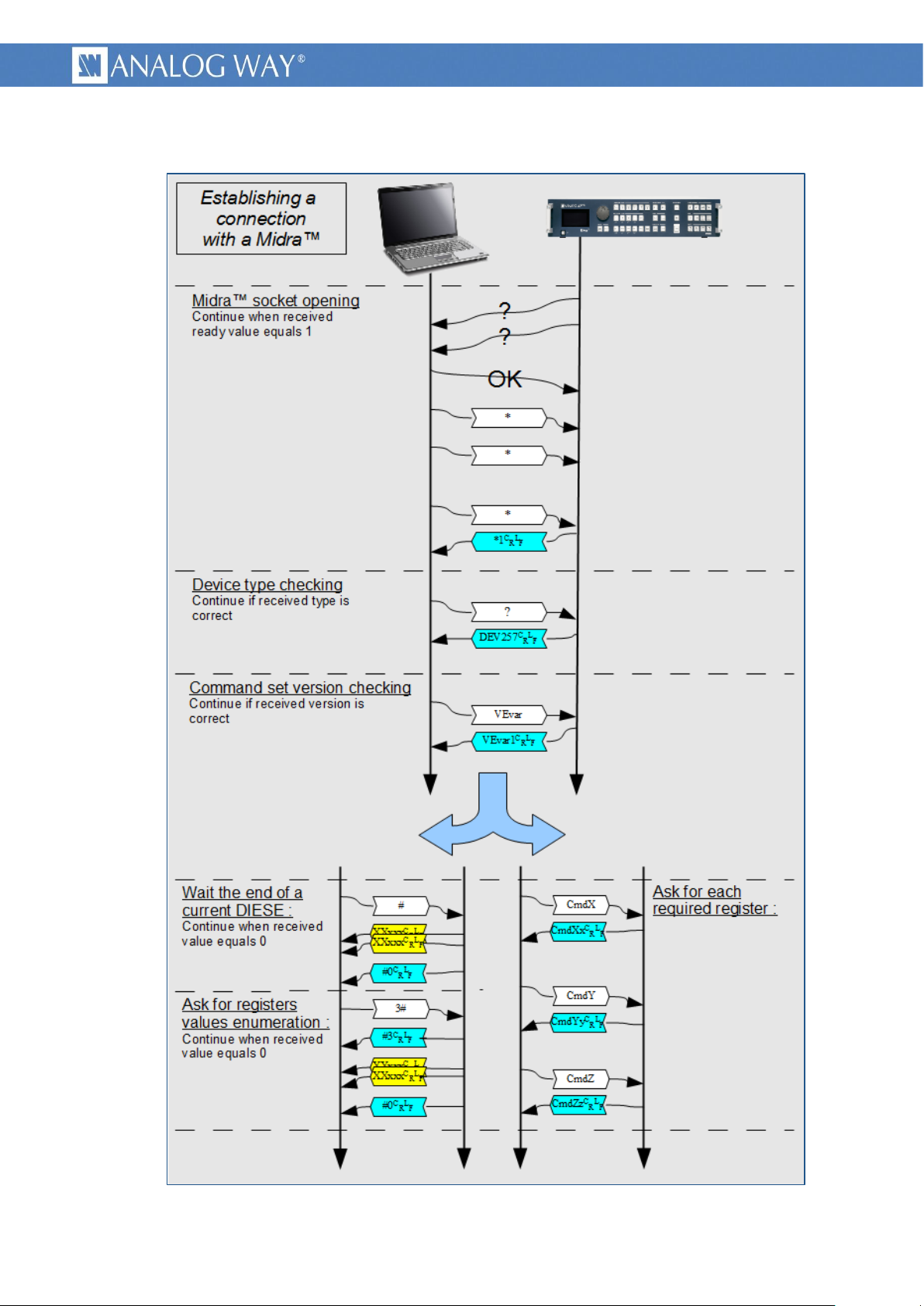
3.1.3 detailed commands sequence
socket opening : As indicated in §CONTROLING MIDRA chapter, TCP/IP must be used to control
Midra™. The device acts as a server. Once the TCP connection is established, the controller shall
check that the device is ready, by reading the READY status, until it returns the value 1.
Syntax : *
Answer : *<value>
CRL
The controller shall wait and retry until it receives the value 1.
F
device type checking : This read only command gives the device type.
Syntax : ?
Answer : DEV<value>
CRL
The numerical <value> gives the
F
connected device type. Other values match other Analog Way devices.
command set version checking : This read only command gives the
version number of the command set. It is recommended to check that
this value matches the one expected by the controller.
Syntax : VEvar
Answer : VEvar1
CRL
Meaning that the device is using a command set in version 1.
F
Midra™ registers read back : This step is recommended to initialize the controller. Various
methods exist, depending on controller software architecture.
To ease this initialization step, the device features the DIESE command, to enumerate (read
back) all its registers current values. This produces a huge amount of data that can saturate the
controller. A command parameter allows reducing this volume by sending only register values
different from their default value. If the volume is still too high, the controller should enumerate
himself all the required registers, at its own rate.
14
Page 15

PROGRAMMER'S GUIDE FOR v01.02.11
o Read back using DIESE command :
At first, the controller should wait a possible current DIESE command to finish.
sending : #
Answer : #<value>
0, meaning that no enumeration is running.
sending : 1#
When <value> is equal to 1, the device will enumerate all its registers values, for all
indexes in case of multidimensional registers.
When <value> is equal to 3, the device works the same way, except that it will not
enumerate registers having their default value, saving some amount of data.
o Registers read back managed by the controller :
The controller should read all used registers, slowly enough to avoid being saturated.
The controller asks for the current state of the DIESE command.
CRL
The controller must wait that the numerical <value> equals
F
CRL
or 3#
F
CRL
F
15
Page 16
PROGRAMMER'S GUIDE FOR v01.02.11
3.1.4 example of connection establishment
Picture 8 : example of connection establishment
16
Page 17
PROGRAMMER'S GUIDE FOR v01.02.11
3.2 Keeping a connection alive with a Midra™
3.2.1 usage
This example gives you the proper way to maintain the connection alive with a Midra™ device. It is
recommended to use this method for future developments. It uses a single command allowing testing the
connection and that the device is alive.
The sending rate should be slow enough to avoid link overload, typically at “human rate”.
It is advised to “ping” the device only when no communication occurs.
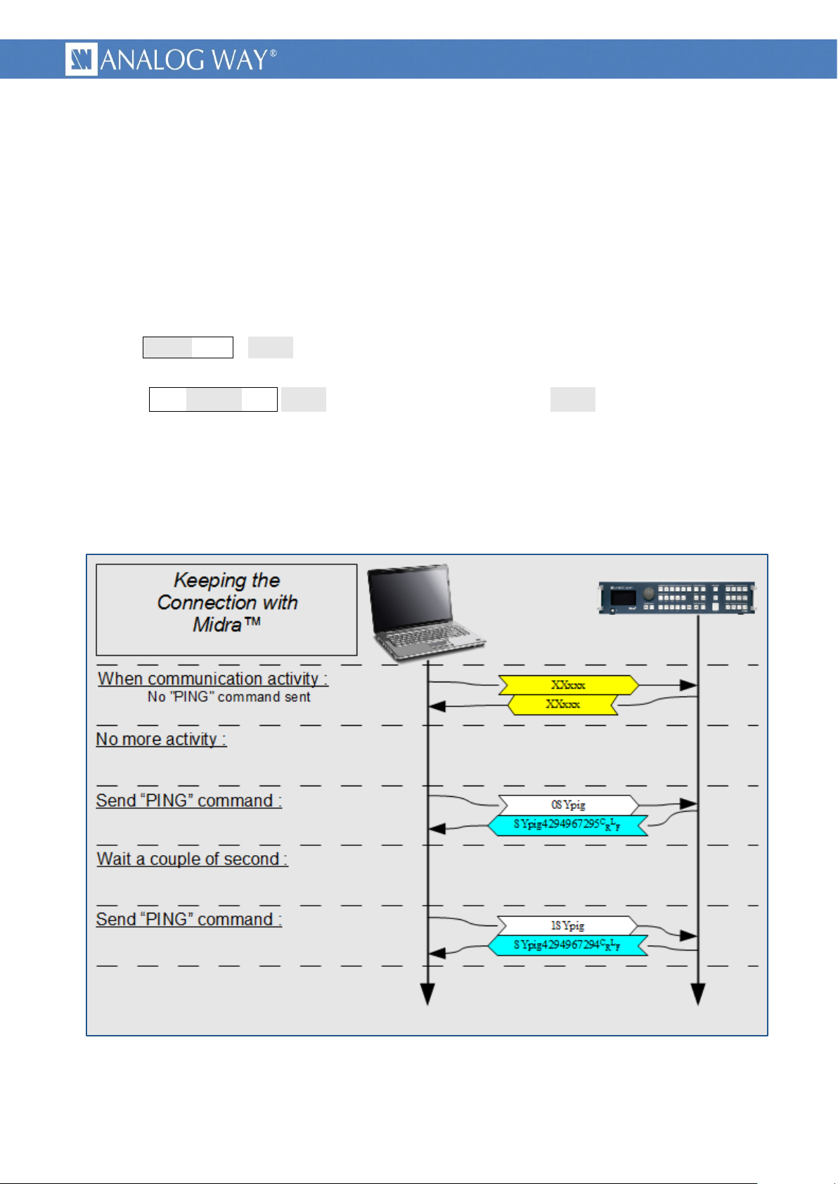
3.2.2 detailed command sequence
Syntax : <val1>SYpig <val1> is any numerical value that will be used and returned inverted by the
device, showing that it is alive.
Answer : SYpig<val2>
Examples : sending 0 (0x0000 0000) will return 4.294.967.295 (0xFFFF FFFF)
sending 1 (0x0000 0001) will return 4.294.967.294 (0xFFFF FFFE)
sending 170 (0x0000 00AA) will return 4.294.967.125 (0xFFFF FF55)
3.2.3 example of PING command
CRL
<val2> is computed by binary inverting <val1>.
F
Picture 9 : example of keeping a connection alive
17
Page 18
PROGRAMMER'S GUIDE FOR v01.02.11
3.3 Changing a source displayed in a layer
<layer>
name
7
Audio
6
Logo2
5
Logo1
4
PIP4
3
PIP3
2
PIP2
1
PIP1
0
Frame
<src>
name
0
No input
1
Input 1 or frame 1
2
Input 2 or frame 2
3
Input 3 or frame 3
4
Input 4 or frame 4
5
Input 5 or frame 5
6
Input 6 or frame 6
7
Input 7 or frame 7
8
Input 8 or frame 8
9
Input 9 or frame 9
10
Input 10 or frame 10
11
Color or Black fill
3.3.1 usage
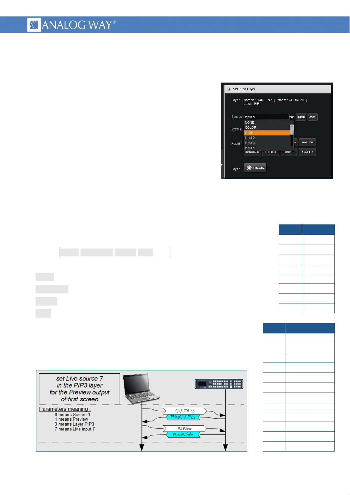
Picture 10 : Changing layer source - RCS²
This example indicates how to change a source displayed in a
layer of a screen, on the Program or Preview output. Source type
can be “live sources”, frames, logos or color.
3.3.2 Midra™ layers reminder
Pictures are displayed on a screen in overlapping layers. Each
layer can only contain a predefined picture type, either “Frame”,
live input or “Logo”, depending on the layer depth.
The first layer is the lowest, it can be covered by any upper
layer and can only display still frame.
The following layers, named “PIP”, can only display live inputs.
Their number depends on device type and mode and it can be known using the OSCREEN_MAX_LAYERS
command.
The following upper layers must be used to display logos.
The last invisible layer is dedicated to audio, allowing it to be processed synchronously with video and
also to be memorized in preset memories.
3.3.3 detailed command parameters
Syntax : <scrn>,<ProgPrev>,<layer>,<src>PRinp
<scrn> is the RCS² screen number minus 1.
<ProgPrev> is 0 for Program, 1 for Preview.
<layer> is a value representing the destination Layer.
<src> is a value representing the input source.
Note that this command shall be followed by an update command, to be
taken in account, as any other preset modification.
3.3.4 example of Preview layer source change
Picture 11 : example of Preview layer source change
18
Page 19

PROGRAMMER'S GUIDE FOR v01.02.11
3.4 TAKE : Transitioning a Preview screen onto a Program screen
3.4.1 usage
The “TAKE” action allows transitioning, for a single screen, the “Preview” content (next state) to the
“Program” (current state) using the current transition.
3.4.2 Midra™ transitions reminder
Picture modifications can be made directly on the program screen (in the “current preset”) or can be
prepared on the preview screen (in the “next preset”) and applied synchronously through the TAKE
command. The device will try to apply all preset changes in one step, using user parameters. Depending on
the complexity of preset changes, it can lack resources and be obliged to use two steps or to sequence the
transition. This status can be read through the TAKEINFO command.
Before launching a TAKE command, the TAKEAVA status shall always be read to wait for the device to
be ready.
3.4.3 detailed commands sequence
Wait for the TAKE availability :
Launch the TAKE action : Launch the TAKE by writing the value 1.
Syntax : <scrn>,1GCtak
L
<scrn> is the RCS² screen number minus 1.
F
Only value 1 is allowed, machine will immediately acknowledge the command, then will do the
transition and last will answer with the 0 value after the end of the TAKE.
3.4.4 example of TAKE
Picture 12 : example of TAKE
19
Page 20

PROGRAMMER'S GUIDE FOR v01.02.11
3.5 TAKE ALL : Transitioning from Preview onto the Program for all screens (matrix mode)
3.5.1 usage
In Matrix mode, the “TAKE ALL” action allows transitioning for all screens, the “Preview” content (next
state) to the “Program” (current state) using the current transition.
3.5.2 Midra™ transitions reminder
Picture modifications can be made directly on either program screens (in the “current preset”) or can
be prepared on the preview screens (in the “next preset”) and applied synchronously through the TAKE
ALL command. The device will try to apply all preset changes in one step on all screens, using user
parameters. Depending on the complexity of preset changes, it can lack resources and be obliged to use
two steps or to sequence the transition. This status can be read through the TAKEINFO command for
screen 1 and for screen 2.
Before launching a TAKE ALL command, the TAKEAVA status shall always be read for screen 1 AND
screen 2 in order to wait for the device to be ready.
3.5.3 detailed commands sequence
Wait for the TAKE availability on screen 1 and on screen 2 :
Launch the TAKE ALL action : Launch the TAKE ALL by writing the value 1.
Syntax : 1,GCtal
L
F
Only value 1 is allowed, machine will immediately acknowledge the command, then will do the
transition on both screens and last will answer with the 0 value after the end of the TAKE ALL command.
3.5.4 example of TAKE ALL
Picture 13 : example of TAKE ALL
20
Page 21

PROGRAMMER'S GUIDE FOR v01.02.11
3.6 Loading a Preset from Master memory to a single Program screen
element to recall
value
Auto-Scale
1
source
2
Pos/Size
4
Transparency
8
Cropping
16
Border
32
Transition
64
Timing
128
Effects
256
Audio layer
512
No filter
0
Picture 14 : Loading Preset from memory - RCS²
3.6.1 usage
A simple way to control a Midra™ product is
to record the entire screen contents in its
memories, using the RCS², during the initial
setup. These memories can then be remotely
recalled by a controller.
The “recall Preset from memory” action is
made of only one command, allowing setting
parameters like memory number, destination
screen, filters.
A filter allows choosing to not recall some elements, like source or layers positions and sizes, etc. It can
be used, for example to include or exclude displayed input from memory recall.
3.6.2 Midra™ “Master preset Memories” reminder
Midra™ allows memorization of up to 8 “Master Memories” inside the device, usable by a controller.
The RCS² software gives 56 other memories, stored in the computer running this software. They are not
usable by a controller.
A “Master Memory” slot contains all preset elements of the 2 screens of a device. Depending on device
type and device mode, only one screen can be available. In this case, the memory part for the second
screen still exists, but nothing is stored in it during saving.
The “PRESET_LOAD_REQUEST” single command allows to reload a single destination screen, from one
of the two part (origin screen) of a “Master Memory” slot.
3.6.3 detailed command parameters
Syntax : <scrnF>,<mem>,<scrnT>,<progPrev>,<fltr>,1GClrq
<fltr> parameter : This parameter allows excluding some preset
elements from recalling.
The <fltr > value can be calculated by adding the values associated
with each element to exclude (filtered elements). Legal values are
from 0 up to 1023. Value 0 means that all preset elements will be
recalled.
<progPrev> parameter : This parameter gives the destination
preset number, either Program (current preset) or Preview (next
preset). The recalled preset is immediately displayed after end of
recall. If the displayed input has to be changed after memory
recall then the Preview preset destination shall be used, followed by the changes of displayed inputs,
ended with the TAKE or with the TAKE ALL command. (see the example bellow)
21
Page 22

PROGRAMMER'S GUIDE FOR v01.02.11
<scrnT> parameter : This parameter gives the destination screen number. If only one screen is
available, due to device type or device mode, the screen number 0 shall be used.
<mem> parameter : This parameter gives the memory slot number to load. The allowed range of
values is 0 to 7, corresponding to memories 1 to 8.
<scrnF> parameter : This parameter gives the origin screen number, the one from which was recorded
the preset. Used with the <scrnT> parameter, they allow loading in a screen a preset stored from the
other, in matrix mode.
3.6.4 example of memorized preset recall
Picture 15 : example of memorized preset recall
22
Page 23

PROGRAMMER'S GUIDE FOR v01.02.11
3.7 Loading a Preset from Master memory and changing the source displayed in a layer
3.7.1 usage
This example combines previous examples showing how to use master memories as a
“layout template”, plus changing a layer source before being displayed on the program output.
3.7.2 detailed commands sequence
Load master memory to preview : See the previous example for parameters explanation. The filter
parameter (<fltr>) can be used to avoid recalling the layer sources. In this case, the memory recall will
be able to change layer positions and sizes, layer borders, without changing layer content.
Syntax : <scrnF>,<mem>,<scrnT>,<prgPrv>,<fltr>,1GClrq
Change the layer source : See this example for parameters explanation. The PE_INPUTNUM command
shall be followed by a PU_SCREEN_UPDATE command to update the screen.
Syntax : <scrn>,<progPrev>,<layer>,<src>PRinp
TAKE, launch the transition from preview to program : See the previous example for parameters
explanation. The TAKEAVA status validity shall be tested before launching the TAKE command.
Syntax : <scrn>,1GCtak
L
<scrn> is the RCS² screen number minus 1.
F
23
Page 24

PROGRAMMER'S GUIDE FOR v01.02.11
3.7.3 example of Master Memory preset recall
Picture 16 : example of Master Memory preset recall
24
Page 25

PROGRAMMER'S GUIDE FOR v01.02.11
3.8 Displaying/Hiding the Quick Frame for one single screen
3.8.1 usage
The Quick Frame is the emergency frame that can be displayed in front of every layer for a given
screen. This example shows how to enable the Quick Frame for Screen 1.
3.8.2 detailed command sequence
Displaying the Quick Frame
Syntax : <scrn>,1CTqfa <scrn> is the RCS² screen number minus 1.
Answer : CTqfa<scrn>,1
CRL
1 indicating that the frame configured as the Quick Frame for <screen> is
F
now displayed above all layers.
Hiding the Quick Frame
Syntax : <scrn>,0CTqfa <scrn> is the RCS² screen number minus 1.
Answer : CTqfa<scrn>,0
CRL
0 indicating that the frame configured as the Quick Frame for <screen> is
F
now hidden.
3.9 Displaying/Hiding the Quick Frames for all screens (matrix mode)
3.9.1 usage
Two different frames can be defined as Quick Frames (or emergency frames) respectively for screen 1
and screen 2. This example shows how to enable the configured Quick Frames simultaneously on Screen 1
and Screen 2.
3.9.2 detailed command sequence
Displaying the Quick Frames on both screens simultaneously
Syntax : 1CTqfl
Answer : CTqfl1
CRL
1 indicating that the Quick Frames configured for Screen 1 and Screen 2 are now
F
displayed above all layers on both screens.
Hiding the Quick Frames on both screens simultaneously
Syntax : 0CTqfl
Answer : CTqfl0
CRL
0 indicating that the Quick Frames configured for Screen 1 and Screen 2 are now
F
hidden on both screens.
25
Page 26

PROGRAMMER'S GUIDE FOR v01.02.11
4 NOTES
4.1 Using this document
This document contains many internal links. You can improve your navigation by using the “previous
page” function, as in the following example:
Picture 17 : PDF reader, Previous and Next page buttons
26
Page 27

Page 28

PROGRAMMER'S GUIDE FOR v01.02.11
V1.00 – Mar/20/2014
28
 Loading...