

Page 1

Programmer’s Guide
For STE200
1
Page 2

A1: Introduction
If you need to use your own Software Control program from a PC or WORKSTATION with an RS-232 or LAN port, the device allows communication
through an ASCII code protocol.
The device treats any character that it receives on the RS-232 or LAN as a possible command but only accepts legal commands.
There is no starting/ending code needed in a command string.
A command can be a single character typed on a keyboard and does not require any special character before or after it.
(It is not necessary to press "ENTER" on the keyboard). A command can be preceded by a value (See chapter A-2).
When the device receives a valid command, it will execute the command. Then it will send back the status of the parameters that have changed due
to this command.
If the command cannot be executed (value out of range, no signal on the selected input),etc. The device will just sends back the current status of
the corresponding parameters.
If the command is invalid, an error response will be returned to the control device. All responses returned to the control device end with
a carriage return <CR> and a line feed <LF> signaling the end of the response character string (see chapter A-3).
A2: Commands structure
The above listed devices share the same code structure.
Commands are made of numerical values for arguments followed by the command characters (one or Two case-sensitive alphabetical letters). Usually the same
characters (letters) are used for the [read Command] as well as the [write command].
The indexes are defined numbers indicating the how the arguments for the command apply. For example a layer number, an input number, a preset number, etc.
They are separated with a comma.
There are commands without index and others with up to 3 indexes. Each index is followed by a comma character. The final argument, also refered to as the “value”
does not have a comma between it and the command.
2
Page 3

A [write command] is made of indexes followed by the numerical value followed by the command characters.
Write command = [[index,] ...] + Value + Character (s) code (s)
For example: “1,2,0IN” or “4YB”
A [read command] is made of indexes followed immediately by the command characters. (no numerical value)
Read command = [[index,] ...] Character (s) code (s)
For example: “1,2,IN” or “YB”
A3: Examples
Document notation:
1) Command with 1 index : OFORMAT
Command to set the Main output format to XGA: 0,12OF
Answer: OF0,12<CR><LF> which mean that the main output format is now 1024x768
2) Command with 2 indexes : PE_INPUTNUM
Command to set the input 4 displayed in background layer of Next Preset: 1,2,4IN
Answer: IN1,1,4<CR><LF> which mean that the background layer of the next preset will display the input 4 signal
3) Read command without index : TAKEAVA
Read command to know if the TAKE command is available: TA
Answer: TA1<CR><LF> which mean that the device is ready to accept the TAKE command.
4) Read command with 2 indexes : SET_ASPECT_RATIO_OUT
Read command to know how is displayed a signal plugged on the input 4: 3,so
Answer: so3,2<CR><LF> which mean that the input 4 is displayed cropped
3
Page 4

A4: Error codes
Answer: E10<CR><LF> which mean invalid command
Answer: E11<CR><LF> which mean index value error (index value out of range)
Answer: E12<CR><LF> which mean index number error (too or few indexes)
Some commands are only available as [Read command], they are status and are colored in blue as this line.
Some commands are colored in yellow as this line to indicate they were added or modified in this version.
A5 COMMUNICATION PORTS
4
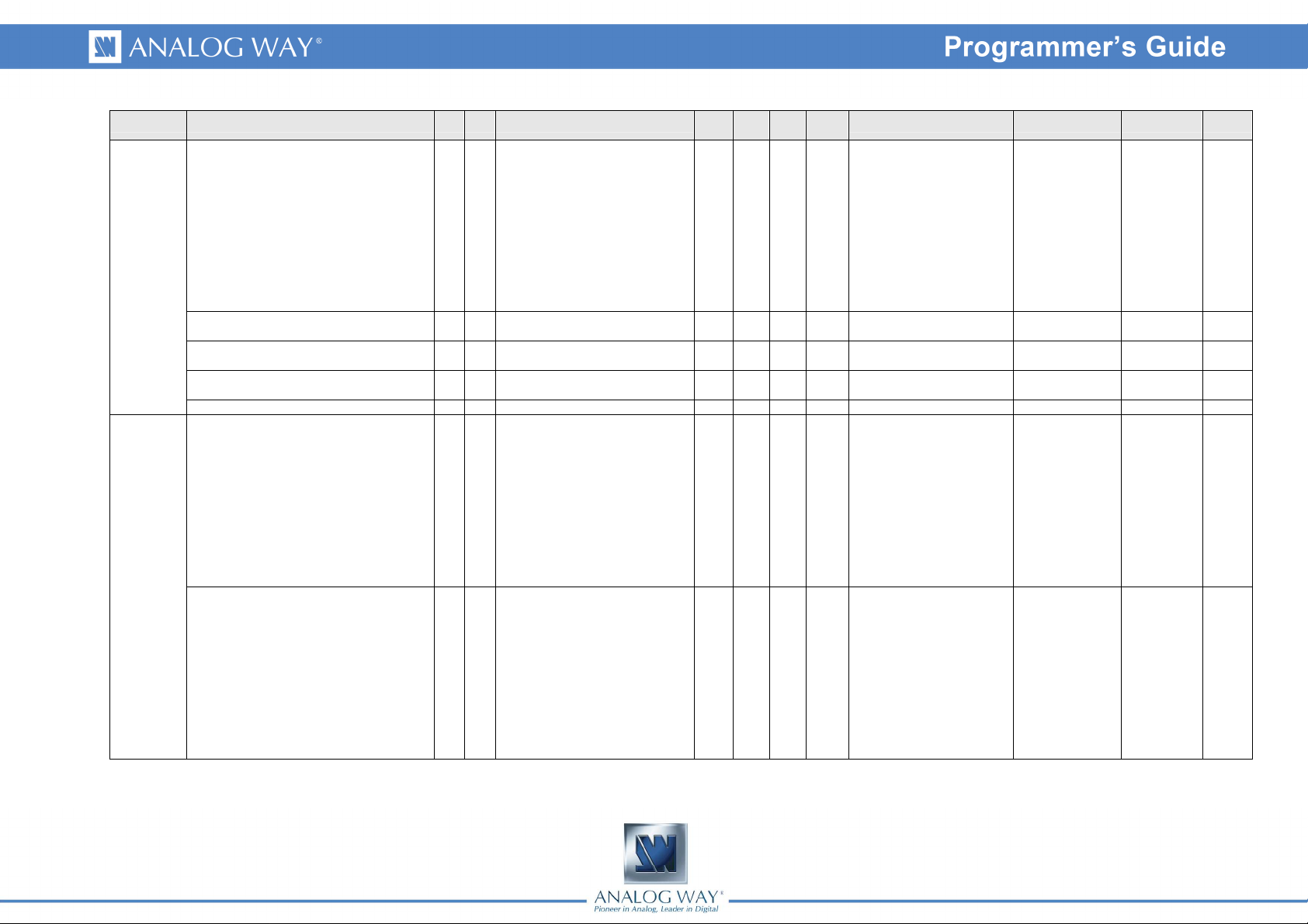
Page 5

Read /
Min
Max
Default
Apply factory settings to the
Auto reset
Auto reset
AXION
AUTO_LOCK
AUTO_TAKE
Automatic Take after an input
AUTO_STEPBACK
Automatic preset toggle after a
Group Name Cmd RespDescription
DIESE # #
SYSTEM
CONTROLS
5
READY * * Ready Device Flag Rd 0 1 0
DEV ? DEV MMS device type Rd 94 94 94 94 = STE_200
UPDATER yU yU Device reboot for update Rd/Wr 0 255 0 1 then 254 => Reboot
FACTORYRESET YR YR
POSMEMORYRESET YE YE Erase stored image settings Rd/Wr 0 1 0
CSTORE YS YS
LOCK YK YK Device locking Rd/Wr 0 2 0
LCDBRIGHTNESS YB YB Front panel display brightness Rd/Wr 1 8 8
KEYBRIGHTNESS Yb Yb Front panel keys brightness Rd/Wr 10 100 100
TBAR_ENABLE YD YD Enable disable T-BAR Rd/Wr 0 1 1
COPKIND CK CK Kind of slow in-progress operation Rd 0 6 0
COPPROGRESS CP CP
SWITCHER_MODE CM CM Device operating mode Rd/Wr 1 1 0 1 = Matrix mode
yA yA Device is driven by Orchestra Rd/Wr 0 1 0
YL YL
YT YT
Ys Ys
FREEZE_MODE Ym Ym Input freeze mode Rd/Wr 0 1 0
Request the retrieval of all the
variables
device( except image settings )
FLASH memory writing in progess.
Do not power off
Progress percent of the slow
operation
Forbide the use of a signal-less
input
change
TAKE
Write
Value
value
Rd/Wr 0 1 0
Rd/Wr 0 1 0
Rd 0 1 0
Rd 0 100 0 Percent : 0 to 100%
Rd/Wr 0 1 1
Rd/Wr 0 1 0
Rd/Wr 0 1 0
Values Index #1 Index #2
value
0= Initialization in progress
1 = Ready
0 = Free
1 = Flash writing in progress
0 = No lock
1 = Locked menu
2 = Locked front panel
1, …, 8 = Brightness level,
12,5% step
1, …, 100 = Brightness level,
1% step
0 = None
1 = Auto centering
2 = Auto setting
3 = StandBy
4 = Picture recording
5 = Reset to default factory
setting
6 = Reset User settings
0 = Device is not driven by
ORC-50
1 = Device is driven by Orc50
0 = Signal less input can be
selected
1 = Signal less input can not
be selected
0 = AUTO-TAKE Disable
1 = AUTO-TAKE Enable
0 = AUTO- PRESETTOGGLE Disable
1 = AUTO- PRESETTOGGLE Enable
0 = Freeze by input
1 = Freeze all inputs
Index #3
Page 6

Read /
Min
Max
Default
Fill PIP with black depending on the
Group Name Cmd RespDescription
Back-up input when an input loose
its signal
Disable the the black fiilng of the
bakgrounfd live layer
aspect ratio
Disable Frame and Ids on the
preview output
Message to wake-up an output
display device ( 50 characters)
Message to send an output display
device to sleep ( 50 characters)
STANDBY
VERSION
FRAME_ALERT Yf Yf
TRANSPARENT_BACKGROUND Yt Yt
BLACK_FILL bF bF
DISABLE_ID bI bI
STDBYSTATUS wS wS Standby mode Rd/Wr 0 1 0
STDBYREQUEST wQ wQ Request for standby or wake up Rd/Wr 0 1 0
STDBYPROJ_ON wN wN
STDBYPROJ_OFF wF wF
STDBYPROJ_RATE wR wR Output display device UART speed Rd/Wr 0 3 2
STDBYPROJ_CTRL wC wC Rd/Wr 0 4 0
VERI1 xi xi Byte 0 and 1 of the device ID Rd 0 65535 0 ex : AAAA
VERI2 xj xj Byte 2 and 3 of the device ID Rd 0 65535 0 ex : AAAA
VERI3 xk xk Byte 4 and 5 of the device ID Rd 0 65535 0 ex : AAAA
VERI4 xl xl Byte 6 and 7 of the device ID Rd 0 65535 0 ex : AAAA
Write
Value
value
Rd/Wr 0 14 0
Rd/Wr 0 1 1
Rd/Wr 0 1 0
Rd/Wr 0 1 0
Rd/Wr 0 255 0 min = 0 max = 49
Rd/Wr 0 255 0 min = 0 max = 49
Values Index #1 Index #2
value
0 = No input
1 = Input1
2 = Input2
3 = Input3
4 = Input4
5 = Input5
6 = Input6
9 = Input9
10 = Input10
11 = Input11
12 = Input12
13 = Input13
14 = Input14
0 = use BLACK_FILL
1 = Disable black filling only
for background
0 = Disable black filling
1 = Enable black filling
0 = Normal mode
1 = Standby mode
0 = Wake up
1 = Standby
0 = 1200bauds
1 = 2400bauds
2 = 9600bauds
3 = 19200bauds
0 = No request
1 = Wake up request
2 = Standby request
3 = Clear Wake up message
4 = Clear standby message
Index #3
6
Page 7

Read /
Min
Max
Default
Auto
Auto
Group Name Cmd RespDescription
VERK xK xK
VERV xV xV Variable set version Rd 0 65535 42
VERUPD xU xU Updater version Rd 0 65535 0
OPT yo yo Detected options Rd 0 65535 0
REV xR xR Moher board revision Rd 0 255 0
IN_AUTOSET_ALL Ia Ia
INPUT
IN_AUTOSET Ii Ii
Checksum/version of the
programmable components
-setting request for all the
inputs
-setting request for the
specified input
Write
Value
value
Rd/Wr 0 65535 0
Rd/Wr 0 1 0
Rd/Wr 0 1 0
Values Index #1 Index #2
value
bit 0 = Lan Module
bit 1 = SDI In 1 board (SDI 1
and 2)
bit 2 = Recording board
bit 3 = CF Caecina
bit 4 = CF Fannia
bit 5 = CF Thrasea
bit 6 = SDI In 2 board (SDI 3
and 4)
bit 7 = Audio Evolution
bit 8 = HDCP DVI In
Evolution
0 = Number of
programmables
components
1 = Main microcontroler
2 = Front panel
micro-controler
3 = FPGA Caecina
4 = FPGA Fannia
5 = FPGA Thrasea
6 = Synchro CPLD
0 = Input1
1 = Input2
2 = Input3
3 = Input4
4 = Input5
5 = Input6
8 = Input9
9 = Input10
10 = Input11
11 = Input12
12 = Input13
13 = Input14
Index #3
7
Page 8

Read /
Min
Max
Default
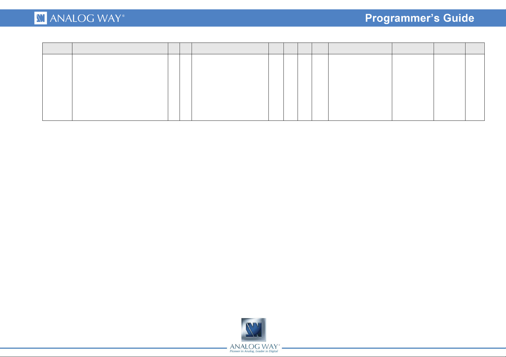
Group Name Cmd RespDescription
IN_USR_FORMAT iU iU
Format/standard of the input signal
corrected by user
Write
Value
value
Rd/Wr 0 42 0
Values Index #1 Index #2
value
0 = None
1 = Invalid
2 = Unknown
3 = SDTV NTSC
4 = SDTV PAL
5 = SDTV SECAM
6 = SDTV BW
7 = SDTV 480i
8 = SDTV 576i
9 = EDTV 480p
10 = EDTV 576p
11 = HDTV 720p
12 = HDTV 1035i
13 = HDTV 1080i
14 = HDTV 1080p
15 = HDTV 1080sF
16 = CPU VGA
17 = CPU 800x480
18 = CPU WVGA
19 = CPU SVGA
20 = CPU 1280x600
21 = CPU 720p RGB
22 = CPU XGA
23 = CPU WXGA
24 = CPU SWXGA
25 = CPU 800p RGB
26 = CPU SWXGA+
27 = CPU 1152x864
28 = CPU 900p RGB
29 = CPU 1600x900
30 = CPU 960p RGB
31 = CPU SXGA
32 = CPU 1360x1024
33 = CPU DILA4/3
34 = CPU SXGA+
35 = CPU WSXGA+
36 = CPU 1080p RGB
37 = CPU 2K
38 = CPU UXGA
39 = CPU WUXGA
40 = CPU 1920x1440
41 = CPU QXGA
42 = CPU 1366x768
0 = Input1
1 = Input2
2 = Input3
3 = Input4
4 = Input5
5 = Input6
8 = Input9
9 = Input10
10 = Input11
11 = Input12
12 = Input13
13 = Input14
Index #3
8
Page 9

Read /
Min
Max
Default
Analog H sync load
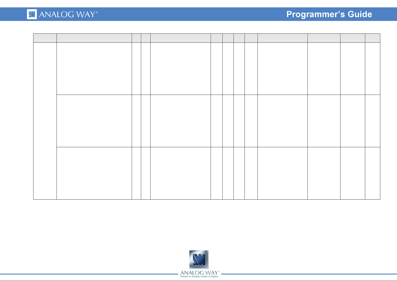
Group Name Cmd RespDescription
IN_TYPE iK iK Input signal type Rd/Wr 0 17 13
IN_SYNC_LOAD il il
Write
Value
value
Rd/Wr 0 1 0
Values Index #1 Index #2
value
0 = SDTV Composite
1 = SDTV Y/C
2 = SDTV/EDTV/HDTV
RGBS TTL/Analog
3 = SDTV/EDTV/HDTV RGB
SOG
4 = SDTV/EDTV/HDTV YUV
5 = Computer SOG
6 = Computer H&V or
Composite (TTL/Analog)
7 = Computer B&W
8 = DVI-D EDTV/HDTV RGB
16-235
9 = DVI-D EDTV/HDTV YUV
10 = DVI-D Computer RGB
0-255
11 = DVI-D Computer RGB
16-235
12 = SDI SDTV/HDTV
13 = Analog Computer,
separated H&V synchro
14 = Analog Computer,
composite TTL synchro
15 = Analog Computer,
composite analog synchro
16 = Analog RGB video,
composite TTL synchro
17 = Analog RGB video,
composite analog synchro
0 = Hi-Z
1 = 75 ohm loaded
0 = Input1
1 = Input2
2 = Input3
3 = Input4
4 = Input5
5 = Input6
8 = Input9
9 = Input10
10 = Input11
11 = Input12
12 = Input13
13 = Input14
0 = Input1
1 = Input2
2 = Input3
3 = Input4
4 = Input5
5 = Input6
8 = Input9
9 = Input10
10 = Input11
11 = Input12
12 = Input13
13 = Input14
Index #3
9
Page 10

Read /
Min
Max
Default
Group Name Cmd RespDescription
IN_USED iu iu Input is enabled Rd/Wr 0 1 1
IN_SD_STD iS iS Decoded video standard Rd/Wr 0 7 0
IN_SD_STA iV iV Video Signal stability Rd/Wr 0 1 1
Write
Value
value
Values Index #1 Index #2
value
0 = Auto
1 = NTSC (M,J)
2 = PAL (BDGHIN)
3 = PAL (M)
4 = PAL (N-Combination)
5 = NTSC 4.43
6 = SECAM
7 = PAL 60
0 = Stable Source ( DVD )
1 = VCR Source ( Video
cassette recorder )
0 = Input1
1 = Input2
2 = Input3
3 = Input4
4 = Input5
5 = Input6
8 = Input9
9 = Input10
10 = Input11
11 = Input12
12 = Input13
13 = Input14
0 = Input1
1 = Input2
2 = Input3
3 = Input4
4 = Input5
5 = Input6
8 = Input9
9 = Input10
10 = Input11
11 = Input12
12 = Input13
13 = Input14
0 = Input1
1 = Input2
2 = Input3
3 = Input4
4 = Input5
5 = Input6
8 = Input9
9 = Input10
10 = Input11
11 = Input12
12 = Input13
13 = Input14
Index #3
10
Page 11

Read /
Min
Max
Default
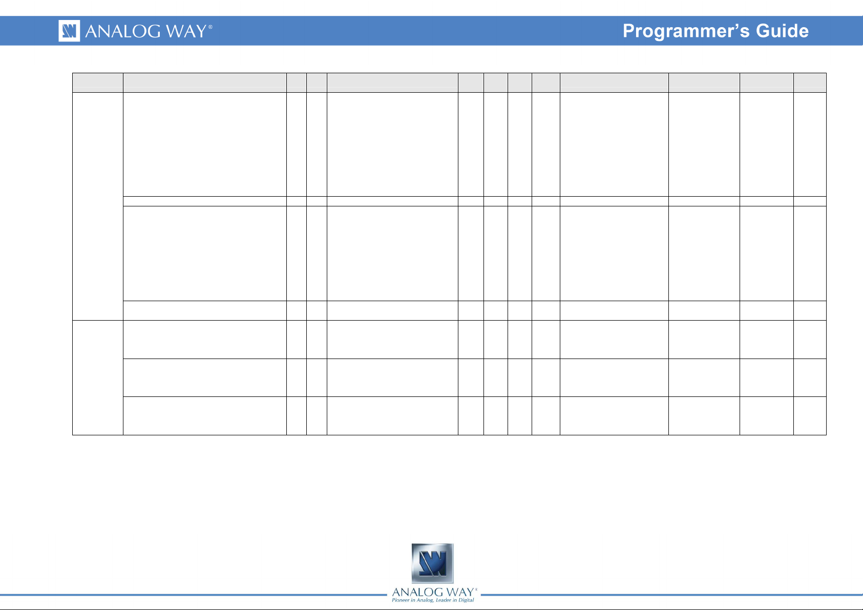
Group Name Cmd RespDescription
IN_SYNCHRONIZED iY iY VIS Synchronisation group Rd/Wr 0 3 0
IN_HDCP_ENABLE iH iH
IN_HDCP_CABLE_LEN iC iC Lenght of an DVI input cable Rd/Wr 0 2 0
IN_KEYING_TYPE KT KT Keying type Rd/Wr 0 4 0
KEYING
IN_KEYING_R_LEVEL KR KR Keying level (Red ) Rd/Wr 0 255 0
Enable/disable the HDCP support
of a DVI input
Write
Value
value
value
Rd/Wr 0 1 1
Values Index #1 Index #2
0 = Input1
0 = Does not belong to any
VIS Group
1 = Groupe VIS 1 group for
analog input
2 = Groupe VIS 2 group for
analog input
3 = Groupe VIS 3 group for
analog input
0 = Less than 10 meter
cable length
1 = 5 to 20 meters cable
length
2 = More than 15 meters
cable length
0 = No keying
1 = Luma Key Keying
2 = ChromaKey Keying
3 = Luma Key Keying + DSK
4 = ChromaKey Keying +
DSK
1 = Input2
2 = Input3
3 = Input4
4 = Input5
5 = Input6
8 = Input9
9 = Input10
10 = Input11
11 = Input12
12 = Input13
13 = Input14
10 = Input11
11 = Input12
10 = Input11
11 = Input12
0 = Input1
1 = Input2
2 = Input3
3 = Input4
4 = Input5
5 = Input6
8 = Input9
9 = Input10
10 = Input11
11 = Input12
12 = Input13
13 = Input14
0 = Input1
1 = Input2
2 = Input3
3 = Input4
4 = Input5
5 = Input6
8 = Input9
9 = Input10
10 = Input11
11 = Input12
12 = Input13
13 = Input14
Index #3
11
Page 12

Read /
Min
Max
Default
Group Name Cmd RespDescription
IN_KEYING_G_LEVEL KG KG Keying level (Green) Rd/Wr 0 255 255
IN_KEYING_B_LEVEL KB KB Keying level (Bule) Rd/Wr 0 255 0
IN_KEYING_TOLER KH KH
Keying Tolerance (for chroma and
luma key)
Write
Value
value
value
Rd/Wr 0 255 10
Values Index #1 Index #2
0 = Input1
1 = Input2
2 = Input3
3 = Input4
4 = Input5
5 = Input6
8 = Input9
9 = Input10
10 = Input11
11 = Input12
12 = Input13
13 = Input14
0 = Input1
1 = Input2
2 = Input3
3 = Input4
4 = Input5
5 = Input6
8 = Input9
9 = Input10
10 = Input11
11 = Input12
12 = Input13
13 = Input14
0 = Input1
1 = Input2
2 = Input3
3 = Input4
4 = Input5
5 = Input6
8 = Input9
9 = Input10
10 = Input11
11 = Input12
12 = Input13
13 = Input14
Index #3
12
Page 13

Read /
Min
Max
Default
Group Name Cmd RespDescription
IN_KEYING_LUMA_LOW_LEVEL KL KL Minimum luma level Rd/Wr 0 255 0
IN_KEYING_LUMA_HIGH_LEVEL KM KM Maximum luma level Rd/Wr 0 255 255
IN_KEYING_DSK_ALPHA KA KA Brightness of DSK background Rd/Wr 0 255 64
Write
Value
value
Values Index #1 Index #2
value
0 = Input1
1 = Input2
2 = Input3
3 = Input4
4 = Input5
5 = Input6
8 = Input9
9 = Input10
10 = Input11
11 = Input12
12 = Input13
13 = Input14
0 = Input1
1 = Input2
2 = Input3
3 = Input4
4 = Input5
5 = Input6
8 = Input9
9 = Input10
10 = Input11
11 = Input12
12 = Input13
13 = Input14
0 = Input1
1 = Input2
2 = Input3
3 = Input4
4 = Input5
5 = Input6
8 = Input9
9 = Input10
10 = Input11
11 = Input12
12 = Input13
13 = Input14
Index #3
13
Page 14
Read /
Min
Max
Default
Auto reset
Group Name Cmd RespDescription
IN_KEYING_INVERT KI KI Invert keying area Rd/Wr 0 1 0
IN_KEYING_GRAB_ENABLE Kg Kg
IN_KEYING_GRAB_GET Kc Kc
IN_KEYING_GRAB_H Kh Kh Horizontal position of the grabber Rd/Wr 0 65535 32768
IN_KEYING_GRAB_V Kv Kv Vertical position of the grabber Rd/Wr 0 65535 32768
SIG_HPOL sh sh Input H sync polarity Rd 0 1 0
INPUT
STATUS
SIG_VPOL sv sv Input V sync polarity Rd 0 1 0
Enable/disable the keying color
grabber mode
Capture the coolor selected by the
grabber and apply the settings
Write
Value
value
Rd/Wr 0 1 0
Rd/Wr 0 1 0
Values Index #1 Index #2
value
0 = Disable the grabber
1 = Enable the grabber
Percent of
OSCREEN_UTIL_H
Precent of
OSCREEN_UTIL_V
0 = Negative Synchro
1 = Positive Synchro
0 = Negative Synchro
1 = Positive Synchro
0 = Input1
1 = Input2
2 = Input3
3 = Input4
4 = Input5
5 = Input6
8 = Input9
9 = Input10
10 = Input11
11 = Input12
12 = Input13
13 = Input14
0 = Input1
1 = Input2
2 = Input3
3 = Input4
4 = Input5
5 = Input6
8 = Input9
9 = Input10
10 = Input11
11 = Input12
12 = Input13
13 = Input14
0 = Input1
1 = Input2
2 = Input3
3 = Input4
4 = Input5
5 = Input6
8 = Input9
9 = Input10
10 = Input11
11 = Input12
12 = Input13
13 = Input14
Index #3
14
Page 15

Read /
Min
Max
Default
Group Name Cmd RespDescription
SIG_SYNC_TYPE sK sK Input sync type Rd 0 3 0
SIG_FREQ_FIELD sf sf Input frame frequency Rd 0 65535 0 Unit = 1/100Hz
SIG_FREQ_LINE sl sl Input line frequency Rd 0 65535 0 Unit = 1/100Hz
Write
Value
value
Values Index #1 Index #2
value
0 = Séparated Synchros H&V
1 = Composite TTL Synchro
2 = Composite Analog
Synchro
3 = Synchro on Green (SOG)
0 = Input1
1 = Input2
2 = Input3
3 = Input4
4 = Input5
5 = Input6
8 = Input9
9 = Input10
10 = Input11
11 = Input12
12 = Input13
13 = Input14
0 = Input1
1 = Input2
2 = Input3
3 = Input4
4 = Input5
5 = Input6
8 = Input9
9 = Input10
10 = Input11
11 = Input12
12 = Input13
13 = Input14
0 = Input1
1 = Input2
2 = Input3
3 = Input4
4 = Input5
5 = Input6
8 = Input9
9 = Input10
10 = Input11
11 = Input12
12 = Input13
13 = Input14
Index #3
15
Page 16
Read /
Min
Max
Default
Group Name Cmd RespDescription
SIG_COMPLETE sc sc Input scan completed Rd 0 1 0
Write
Value
value
Values Index #1 Index #2
value
0 = scan in progress or failed
1 = scan completed
0 = Input1
1 = Input2
2 = Input3
3 = Input4
4 = Input5
5 = Input6
8 = Input9
9 = Input10
10 = Input11
11 = Input12
12 = Input13
13 = Input14
Index #3
16
Page 17

Read /
Min
Max
Default
Group Name Cmd RespDescription
SIG_DETECTED_FORMAT sD sD Input detected format name Rd 0 42 0
Write
Value
value
Values Index #1 Index #2
value
0 = None
1 = Invalid
2 = Unknown
3 = SDTV NTSC
4 = SDTV PAL
5 = SDTV SECAM
6 = SDTV BW
7 = SDTV 480i
8 = SDTV 576i
9 = EDTV 480p
10 = EDTV 576p
11 = HDTV 720p
12 = HDTV 1035i
13 = HDTV 1080i
14 = HDTV 1080p
15 = HDTV 1080sF
16 = CPU VGA
17 = CPU 800x480
18 = CPU WVGA
19 = CPU SVGA
20 = CPU 1280x600
21 = CPU 720p RGB
22 = CPU XGA
23 = CPU WXGA
24 = CPU SWXGA
25 = CPU 800p RGB
26 = CPU SWXGA+
27 = CPU 1152x864
28 = CPU 900p RGB
29 = CPU 1600x900
30 = CPU 960p RGB
31 = CPU SXGA
32 = CPU 1360x1024
33 = CPU DILA4/3
34 = CPU SXGA+
35 = CPU WSXGA+
36 = CPU 1080p RGB
37 = CPU 2K
38 = CPU UXGA
39 = CPU WUXGA
40 = CPU 1920x1440
41 = CPU QXGA
42 = CPU 1366x768
0 = Input1
1 = Input2
2 = Input3
3 = Input4
4 = Input5
5 = Input6
8 = Input9
9 = Input10
10 = Input11
11 = Input12
12 = Input13
13 = Input14
Index #3
17
Page 18

Read /
Min
Max
Default
Group Name Cmd RespDescription
SIG_CURRENT_FORMAT sF sF Input current format name Rd 0 42 0
Write
Value
value
Values Index #1 Index #2
value
0 = None
1 = Invalid
2 = Unknown
3 = SDTV NTSC
4 = SDTV PAL
5 = SDTV SECAM
6 = SDTV BW
7 = SDTV 480i
8 = SDTV 576i
9 = EDTV 480p
10 = EDTV 576p
11 = HDTV 720p
12 = HDTV 1035i
13 = HDTV 1080i
14 = HDTV 1080p
15 = HDTV 1080sF
16 = CPU VGA
17 = CPU 800x480
18 = CPU WVGA
19 = CPU SVGA
20 = CPU 1280x600
21 = CPU 720p RGB
22 = CPU XGA
23 = CPU WXGA
24 = CPU SWXGA
25 = CPU 800p RGB
26 = CPU SWXGA+
27 = CPU 1152x864
28 = CPU 900p RGB
29 = CPU 1600x900
30 = CPU 960p RGB
31 = CPU SXGA
32 = CPU 1360x1024
33 = CPU DILA4/3
34 = CPU SXGA+
35 = CPU WSXGA+
36 = CPU 1080p RGB
37 = CPU 2K
38 = CPU UXGA
39 = CPU WUXGA
40 = CPU 1920x1440
41 = CPU QXGA
42 = CPU 1366x768
0 = Input1
1 = Input2
2 = Input3
3 = Input4
4 = Input5
5 = Input6
8 = Input9
9 = Input10
10 = Input11
11 = Input12
12 = Input13
13 = Input14
Index #3
18
Page 19

Read /
Min
Max
Default
with the detected format
Group Name Cmd RespDescription
SIG_FORMAT_LIST sL sL
SIG_SCANTYPE ss ss Input scan type Rd 0 3 0
SIG_HTOTAL_THEORIC sH sH Total number of pixels per line Rd 0 65535 0 Unit = pixels
Bit field of the fomats compatible
Write
Value
value
Rd 0 255 0
Values Index #1 Index #2
value
0 = Progressive
1 = Interleaved, Top field first
2 = Interleaved, Bottom field
first
3 = Segmented frame
0 = Input1
1 = Input2
2 = Input3
3 = Input4
4 = Input5
5 = Input6
8 = Input9
9 = Input10
10 = Input11
11 = Input12
12 = Input13
13 = Input14
0 = Input1
1 = Input2
2 = Input3
3 = Input4
4 = Input5
5 = Input6
8 = Input9
9 = Input10
10 = Input11
11 = Input12
12 = Input13
13 = Input14
0 = Input1
1 = Input2
2 = Input3
3 = Input4
4 = Input5
5 = Input6
8 = Input9
9 = Input10
10 = Input11
11 = Input12
12 = Input13
13 = Input14
0 = Bits 0 to 7
Slice
1 = Bits 8 to
15 Slice
2 = Bits 16 to
23 Slice
3 = Bits 24 to
31 Slice
4 = Bits 32 to
39 Slice
5 = Bits 40 to
47 Slice
Index #3
19
Page 20
Read /
Min
Max
Default
Group Name Cmd RespDescription
SIG_HTOTAL_MAXI sM sM
SIG_WIDTH sw sw Input displayed pixel count Rd 0 65535 0 Unit = pixels
SIG_HEIGHT st st Input displayed line count Rd 0 65535 0 Unit = pixels
Maximal number of pixels per input
line
Write
Value
value
Rd 0 65535 0 Unit = pixels
Values Index #1 Index #2
value
0 = Input1
1 = Input2
2 = Input3
3 = Input4
4 = Input5
5 = Input6
8 = Input9
9 = Input10
10 = Input11
11 = Input12
12 = Input13
13 = Input14
0 = Input1
1 = Input2
2 = Input3
3 = Input4
4 = Input5
5 = Input6
8 = Input9
9 = Input10
10 = Input11
11 = Input12
12 = Input13
13 = Input14
0 = Input1
1 = Input2
2 = Input3
3 = Input4
4 = Input5
5 = Input6
8 = Input9
9 = Input10
10 = Input11
11 = Input12
12 = Input13
13 = Input14
Index #3
20
Page 21

Read /
Min
Max
Default
Group Name Cmd RespDescription
SIG_HDCP sn sn Input HDCP status Rd 0 1 0
SIG_MEM_SLOT sS sS Memory slot index Rd 0 255 255
INPUT
SETTINGS
SET_HPOS SH SH Input horizontal position Rd/Wr 0 2048 1024 1024 = neutral
Write
Value
value
Values Index #1 Index #2
value
0 = Input1
1 = Input2
2 = Input3
3 = Input4
4 = Input5
5 = Input6
8 = Input9
9 = Input10
10 = Input11
11 = Input12
12 = Input13
13 = Input14
0 = Input1
1 = Input2
2 = Input3
3 = Input4
4 = Input5
5 = Input6
8 = Input9
9 = Input10
10 = Input11
11 = Input12
12 = Input13
13 = Input14
0 = Input1
1 = Input2
2 = Input3
3 = Input4
4 = Input5
5 = Input6
8 = Input9
9 = Input10
10 = Input11
11 = Input12
12 = Input13
13 = Input14
Index #3
21
Page 22

Read /
Min
Max
Default
Group Name Cmd RespDescription
SET_VPOS SV SV Input vertical position Rd/Wr 0 2048 1024 1024 = neutral
SET_HSIZE Sw Sw Input horizontal size Rd/Wr 0 4096 2048 2048 = neutral
SET_VSIZE Sh Sh Input vertical size Rd/Wr 0 4096 2048 2048 = neutral
Write
Value
value
Values Index #1 Index #2
value
0 = Input1
1 = Input2
2 = Input3
3 = Input4
4 = Input5
5 = Input6
8 = Input9
9 = Input10
10 = Input11
11 = Input12
12 = Input13
13 = Input14
0 = Input1
1 = Input2
2 = Input3
3 = Input4
4 = Input5
5 = Input6
8 = Input9
9 = Input10
10 = Input11
11 = Input12
12 = Input13
13 = Input14
0 = Input1
1 = Input2
2 = Input3
3 = Input4
4 = Input5
5 = Input6
8 = Input9
9 = Input10
10 = Input11
11 = Input12
12 = Input13
13 = Input14
Index #3
22
Page 23

Read /
Min
Max
Default
Group Name Cmd RespDescription
SET_BRIGHTNESS Sg Sg Input brightness Rd/Wr 0 255 128 128 = neutral
SET_CONTRAST Sc Sc Input Contrast Rd/Wr 0 255 128 128 = neutral
SET_COLOR Sr Sr Input color level Rd/Wr 0 255 128 128 = neutral
Write
Value
value
Values Index #1 Index #2
value
0 = Input1
1 = Input2
2 = Input3
3 = Input4
4 = Input5
5 = Input6
8 = Input9
9 = Input10
10 = Input11
11 = Input12
12 = Input13
13 = Input14
0 = Input1
1 = Input2
2 = Input3
3 = Input4
4 = Input5
5 = Input6
8 = Input9
9 = Input10
10 = Input11
11 = Input12
12 = Input13
13 = Input14
0 = Input1
1 = Input2
2 = Input3
3 = Input4
4 = Input5
5 = Input6
8 = Input9
9 = Input10
10 = Input11
11 = Input12
12 = Input13
13 = Input14
Index #3
23
Page 24

Read /
Min
Max
Default
Group Name Cmd RespDescription
SET_HUE Su Su Input hue (NTSC only) Rd/Wr 0 255 128 128 = neutral
SET_HTOTAL ST ST Input total pixel per line Rd/Wr 0 65535 0 Unit = pixels.
SET_PHASE SS SS Input Phase Rd/Wr 0 31 16
Write
Value
value
Values Index #1 Index #2
value
0 = Input1
1 = Input2
2 = Input3
3 = Input4
4 = Input5
5 = Input6
8 = Input9
9 = Input10
10 = Input11
11 = Input12
12 = Input13
13 = Input14
0 = Input1
1 = Input2
2 = Input3
3 = Input4
4 = Input5
5 = Input6
8 = Input9
9 = Input10
10 = Input11
11 = Input12
12 = Input13
13 = Input14
0 = Input1
1 = Input2
2 = Input3
3 = Input4
4 = Input5
5 = Input6
8 = Input9
9 = Input10
10 = Input11
11 = Input12
12 = Input13
13 = Input14
Index #3
24
Page 25

Read /
Min
Max
Default
Auto reset
ADC R channel adjustment
ADC G channel adjustment
Group Name Cmd RespDescription
SET_AUTOCAD Sa Sa Input autocentering reques Rd/Wr 0 1 0
SET_USER_GAIN_R sr sr
SET_USER_GAIN_G sg sg
(advanced setting)
(advanced setting)
Write
Value
value
Rd/Wr 0 255 128 128 = neutral
Rd/Wr 0 255 128 128 = neutral
Values Index #1 Index #2
value
0 = Input1
1 = Input2
2 = Input3
3 = Input4
4 = Input5
5 = Input6
8 = Input9
9 = Input10
10 = Input11
11 = Input12
12 = Input13
13 = Input14
0 = Input1
1 = Input2
2 = Input3
3 = Input4
4 = Input5
5 = Input6
8 = Input9
9 = Input10
10 = Input11
11 = Input12
12 = Input13
13 = Input14
0 = Input1
1 = Input2
2 = Input3
3 = Input4
4 = Input5
5 = Input6
8 = Input9
9 = Input10
10 = Input11
11 = Input12
12 = Input13
13 = Input14
Index #3
25
Page 26

Read /
Min
Max
Default
ADC B channel adjustment
Group Name Cmd RespDescription
SET_USER_GAIN_B sb sb
SET_PULLDOWN_2_2 Sn Sn
SET_PULLDOWN_3_2 Sp Sp
(advanced setting)
Enable/disable the auto 2:2
pulldown
Enable/disable the auto 3:2
pulldown
Write
Value
value
Rd/Wr 0 255 128 128 = neutral
Rd/Wr 0 1 1
Rd/Wr 0 1 1
Values Index #1 Index #2
value
0 = Disable automatic
detection
1 = Enable automatic
detection
0 = Disable automatic
detection
1 = Enable automatic
detection
0 = Input1
1 = Input2
2 = Input3
3 = Input4
4 = Input5
5 = Input6
8 = Input9
9 = Input10
10 = Input11
11 = Input12
12 = Input13
13 = Input14
0 = Input1
1 = Input2
2 = Input3
3 = Input4
4 = Input5
5 = Input6
8 = Input9
9 = Input10
10 = Input11
11 = Input12
12 = Input13
13 = Input14
0 = Input1
1 = Input2
2 = Input3
3 = Input4
4 = Input5
5 = Input6
8 = Input9
9 = Input10
10 = Input11
11 = Input12
12 = Input13
13 = Input14
Index #3
26
Page 27

Read /
Min
Max
Default
Group Name Cmd RespDescription
SET_CROP_WIN_POS_H SI SI
SET_CROP_WIN_POS_V SJ SJ Cropping window vertical position Rd/Wr 0 65535 32768
SET_CROP_WIN_SIZE_H SK SK Horizontal cropping Rd/Wr 0 58981 0 Percent = 65535 = 100%
Cropping window horizontal
position
Write
Value
value
value
Rd/Wr 0 65535 32768
Values Index #1 Index #2
0 = Input1
1 = Input2
2 = Input3
3 = Input4
Percent = 65535 = 100% : all
cropping on the left
Percent = 65535 = 100% : all
cropping on the top
4 = Input5
5 = Input6
8 = Input9
9 = Input10
10 = Input11
11 = Input12
12 = Input13
13 = Input14
0 = Input1
1 = Input2
2 = Input3
3 = Input4
4 = Input5
5 = Input6
8 = Input9
9 = Input10
10 = Input11
11 = Input12
12 = Input13
13 = Input14
0 = Input1
1 = Input2
2 = Input3
3 = Input4
4 = Input5
5 = Input6
8 = Input9
9 = Input10
10 = Input11
11 = Input12
12 = Input13
13 = Input14
Index #3
27
Page 28

Read /
Min
Max
Default
without black stripes
Group Name Cmd RespDescription
SET_CROP_WIN_SIZE_V SL SL Vertical cropping Rd/Wr 0 58981 0 Percent = 65535 = 100%
SET_ASPECT_RATIO_IN si si Input image aspect ratio Rd/Wr 0 4 0
SET_ASPECT_RATIO_OUT so so Output image aspect ratio Rd/Wr 0 3 1
Write
Value
value
Values Index #1 Index #2
value
0 = 4/3 Fullscreen
1 = 4/3 with 16/9 content +
black stripes
2 = 4/3 with 2.35 content +
black stripes
3 = 4/3 with 16/9 content
4 = 19/9 with 4/3 content +
black stripes
0 = Distorted, input aspect
ratio not preserved
1 = Not distorted, black
bands added
2 = Not distorted, no black
bands added
3 = Not distorted and no
scaling
0 = Input1
1 = Input2
2 = Input3
3 = Input4
4 = Input5
5 = Input6
8 = Input9
9 = Input10
10 = Input11
11 = Input12
12 = Input13
13 = Input14
0 = Input1
1 = Input2
2 = Input3
3 = Input4
4 = Input5
5 = Input6
8 = Input9
9 = Input10
10 = Input11
11 = Input12
12 = Input13
13 = Input14
0 = Input1
1 = Input2
2 = Input3
3 = Input4
4 = Input5
5 = Input6
8 = Input9
9 = Input10
10 = Input11
11 = Input12
12 = Input13
13 = Input14
Index #3
28
Page 29

Read /
Min
Max
Default
Group Name Cmd RespDescription
SET_OVER_SCAN sO sO input image Overscan/Underscan Rd/Wr 0 1 1
SET_FORCE_4_3 SF SF
SET_RESET_SETTINGS Ss Ss Current input default settings Rd/Wr 0 1 0
Force the aspect ratio of
PAL/NTSC input to 4/3
Write
Value
value
Rd/Wr 0 1 1 1 = forced
Values Index #1 Index #2
value
0 = Input1
1 = Input2
2 = Input3
3 = Input4
4 = Input5
5 = Input6
8 = Input9
9 = Input10
10 = Input11
11 = Input12
12 = Input13
13 = Input14
0 = Input1
1 = Input2
2 = Input3
3 = Input4
4 = Input5
5 = Input6
8 = Input9
9 = Input10
10 = Input11
11 = Input12
12 = Input13
13 = Input14
0 = Input1
1 = Input2
2 = Input3
3 = Input4
4 = Input5
5 = Input6
8 = Input9
9 = Input10
10 = Input11
11 = Input12
12 = Input13
13 = Input14
Index #3
29
Page 30

Read /
Min
Max
Default
Displayed input number or frame or
3 = Memory Preset
4 = Memory Preset
5 = Memory Preset
6 = Memory Preset
Preset
8 = Memory Preset
9 = Memory Preset
Group Name Cmd RespDescription
SET_FREEZE Sf Sf Freeze of the input Rd/Wr 0 1 0 1 = Freeze
0 : max correction; 15 : min
correction
logo number
PRESET
ELEMENT
SET_MOTION_DETECT Sm Sm
PE_INPUTNUM IN IN
Write
Value
value
value
Rd/Wr 0 15 15
Rd/Wr 0 14 0
Values Index #1 Index #2
0 = Input1
1 = Input2
2 = Input3
3 = Input4
4 = Input5
0 = No input
1 = Input1
2 = Input2
3 = Input3
4 = Input4
5 = Input5
6 = Input6
9 = Input9
10 = Input10
11 = Input11
12 = Input12
13 = Input13
14 = Input14
5 = Input6
8 = Input9
9 = Input10
10 = Input11
11 = Input12
12 = Input13
13 = Input14
0 = Input1
1 = Input2
2 = Input3
3 = Input4
4 = Input5
5 = Input6
8 = Input9
9 = Input10
10 = Input11
11 = Input12
12 = Input13
13 = Input14
0 = Current preset
1 = Next preset
2 = Previous
preset
1
2
3
4
7 = Memory
5
6
7
10 = Memory
Preset 8
0 =
Background
Frame
2 =
Background
Layer
3 = Pip 1
Layer
6 = Logo 1
8 = Audio
Output 1
9 = Audio
Output 2
Index #3
30
Page 31

Read /
Min
Max
Default
3 = Memory Preset
4 = Memory Preset
5 = Memory Preset
6 = Memory Preset
7 = Memory Preset
8 = Memory Preset
9 = Memory Preset
Auxiliary input mixing enable
3 = Memory Preset
4 = Memory Preset
5 = Memory Preset
6 = Memory Preset
7 = Memory Preset
8 = Memory Preset
9 = Memory Preset
Group Name Cmd RespDescription
PE_SOURCENUM IS IS Source number Rd/Wr 0 64 0 Same Orc-50
PE_AUDIO_AUX_MUTE Aa Aa
Write
Value
value
Rd/Wr 0 1 0 1 = Enable.
Values Index #1 Index #2
value
0 = Current preset
1 = Next preset
2 = Previous
preset
1
2
3
4
5
6
7
10 = Memory
Preset 8
0 = Current preset
1 = Next preset
2 = Previous
preset
1
2
3
4
5
6
7
10 = Memory
Preset 8
0 =
Background
Frame for
output 1
2 =
Background
Layer for
output 1
3 = Pip 1
Layer for
output1
Background
Layer for
output 2 in
matrix mode
6 = Logo 1
8 = Audio
Output 1
9 = Audio
Output 2
0 =
Background
Frame for
output 1
2 =
Background
Layer for
output 1
3 = Pip 1
Layer for
output1
Background
Layer for
output 2 in
matrix mode
6 = Logo 1
8 = Audio
Output 1
9 = Audio
Output 2
Index #3
31
Page 32

Read /
Min
Max
Default
3 = Memory Preset
4 = Memory Preset
5 = Memory Preset
6 = Memory Preset
7 = Memory Preset
8 = Memory Preset
9 = Memory Preset
3 = Memory Preset
4 = Memory Preset
5 = Memory Preset
6 = Memory Preset
7 = Memory Preset
8 = Memory Preset
9 = Memory Preset
Group Name Cmd RespDescription
PE_SMOOTH_MOVE ps ps « Smooth Move » activation Rd/Wr 0 1 1 1 = Enable.
PE_FLIP pf pf Flip de la source Rd/Wr 0 3 0
Write
Value
value
Values Index #1 Index #2
value
0 = No flip
1 = Horizontal flip
2 = Vertical flip
3 = Both Horizontal and
vertical flip
0 = Current preset
1 = Next preset
2 = Previous
preset
1
2
3
4
5
6
7
10 = Memory
Preset 8
0 = Current preset
1 = Next preset
2 = Previous
preset
1
2
3
4
5
6
7
10 = Memory
Preset 8
0 =
Background
Frame for
output 1
2 =
Background
Layer for
output 1
3 = Pip 1
Layer for
output1
Background
Layer for
output 2 in
matrix mode
6 = Logo 1
8 = Audio
Output 1
9 = Audio
Output 2
0 =
Background
Frame for
output 1
2 =
Background
Layer for
output 1
3 = Pip 1
Layer for
output1
Background
Layer for
output 2 in
matrix mode
6 = Logo 1
8 = Audio
Output 1
9 = Audio
Output 2
Index #3
32
Page 33

Read /
Min
Max
Default
3 = Memory Preset
4 = Memory Preset
5 = Memory Preset
6 = Memory Preset
7 = Memory Preset
8 = Memory Preset
9 = Memory Preset
3 = Memory Preset
4 = Memory Preset
5 = Memory Preset
6 = Memory Preset
7 = Memory Preset
8 = Memory Preset
9 = Memory Preset
Group Name Cmd RespDescription
PE_NEW_ID pN pN Unique layer identifier number Rd/Wr 0 1 0
PE_POS_H pH pH
Layer left H position on output
screen
Write
Value
value
value
Rd/Wr 0 65535 32768
Values Index #1 Index #2
Unit = pixels ( 32768 =
screen left border )
0 = Current preset
1 = Next preset
2 = Previous
preset
1
2
3
4
5
6
7
10 = Memory
Preset 8
0 = Current preset
1 = Next preset
2 = Previous
preset
1
2
3
4
5
6
7
10 = Memory
Preset 8
0 =
Background
Frame for
output 1
2 =
Background
Layer for
output 1
3 = Pip 1
Layer for
output1
Background
Layer for
output 2 in
matrix mode
6 = Logo 1
8 = Audio
Output 1
9 = Audio
Output 2
0 =
Background
Frame for
output 1
2 =
Background
Layer for
output 1
3 = Pip 1
Layer for
output1
Background
Layer for
output 2 in
matrix mode
6 = Logo 1
8 = Audio
Output 1
9 = Audio
Output 2
Index #3
33
Page 34

Read /
Min
Max
Default
3 = Memory Preset
4 = Memory Preset
5 = Memory Preset
6 = Memory Preset
7 = Memory Preset
8 = Memory Preset
9 = Memory Preset
3 = Memory Preset
4 = Memory Preset
5 = Memory Preset
6 = Memory Preset
7 = Memory Preset
8 = Memory Preset
9 = Memory Preset
Group Name Cmd RespDescription
PE_POS_V pV pV
PE_SIZE_H pW pW
Layer top V position on output
screen
Layer H size on output screen
(without borders)
Write
Value
value
value
Rd/Wr 0 65535 32768
Rd/Wr 0 65535 1600
Values Index #1 Index #2
Unit = pixels ( 32768 =
screen top border )
Unit = pixels ( Max=16x2048
= 32768)
0 = Current preset
1 = Next preset
2 = Previous
preset
1
2
3
4
5
6
7
10 = Memory
Preset 8
0 = Current preset
1 = Next preset
2 = Previous
preset
1
2
3
4
5
6
7
10 = Memory
Preset 8
0 =
Background
Frame for
output 1
2 =
Background
Layer for
output 1
3 = Pip 1
Layer for
output1
Background
Layer for
output 2 in
matrix mode
6 = Logo 1
8 = Audio
Output 1
9 = Audio
Output 2
0 =
Background
Frame for
output 1
2 =
Background
Layer for
output 1
3 = Pip 1
Layer for
output1
Background
Layer for
output 2 in
matrix mode
6 = Logo 1
8 = Audio
Output 1
9 = Audio
Output 2
Index #3
34
Page 35

Read /
Min
Max
Default
3 = Memory Preset
4 = Memory Preset
5 = Memory Preset
6 = Memory Preset
7 = Memory Preset
8 = Memory Preset
9 = Memory Preset
3 = Memory Preset
4 = Memory Preset
5 = Memory Preset
6 = Memory Preset
7 = Memory Preset
8 = Memory Preset
9 = Memory Preset
Group Name Cmd RespDescription
PE_SIZE_V pS pS
PE_CROP_WIN_POS_H CH CH
Layer V size on output screen
(without borders)
Cropping window horizontal
position
Write
Value
value
value
Rd/Wr 0 65535 1200
Rd/Wr 0 65535 32768
Values Index #1 Index #2
Unit = pixels (Max=16x2048
= 32768)
Unit = percent ( 65535 =
100% = : all cropping on the
left )
0 = Current preset
1 = Next preset
2 = Previous
preset
1
2
3
4
5
6
7
10 = Memory
Preset 8
0 = Current preset
1 = Next preset
2 = Previous
preset
1
2
3
4
5
6
7
10 = Memory
Preset 8
0 =
Background
Frame for
output 1
2 =
Background
Layer for
output 1
3 = Pip 1
Layer for
output1
Background
Layer for
output 2 in
matrix mode
6 = Logo 1
8 = Audio
Output 1
9 = Audio
Output 2
0 =
Background
Frame for
output 1
2 =
Background
Layer for
output 1
3 = Pip 1
Layer for
output1
Background
Layer for
output 2 in
matrix mode
6 = Logo 1
8 = Audio
Output 1
9 = Audio
Output 2
Index #3
35
Page 36

Read /
Min
Max
Default
3 = Memory Preset
4 = Memory Preset
5 = Memory Preset
6 = Memory Preset
7 = Memory Preset
8 = Memory Preset
9 = Memory Preset
3 = Memory Preset
4 = Memory Preset
5 = Memory Preset
6 = Memory Preset
7 = Memory Preset
8 = Memory Preset
9 = Memory Preset
Group Name Cmd RespDescription
PE_CROP_WIN_POS_V CV CV Cropping window vertical position Rd/Wr 0 65535 32768
PE_CROP_WIN_SIZE_H CW CW Horizontal cropping Rd/Wr 0 58981 0 Percent = 65535 = 100%
Write
Value
value
Values Index #1 Index #2
value
Unit = percent ( 65535 =
100% = : all cropping on the
top )
0 = Current preset
1 = Next preset
2 = Previous
preset
1
2
3
4
5
6
7
10 = Memory
Preset 8
0 = Current preset
1 = Next preset
2 = Previous
preset
1
2
3
4
5
6
7
10 = Memory
Preset 8
0 =
Background
Frame for
output 1
2 =
Background
Layer for
output 1
3 = Pip 1
Layer for
output1
Background
Layer for
output 2 in
matrix mode
6 = Logo 1
8 = Audio
Output 1
9 = Audio
Output 2
0 =
Background
Frame for
output 1
2 =
Background
Layer for
output 1
3 = Pip 1
Layer for
output1
Background
Layer for
output 2 in
matrix mode
6 = Logo 1
8 = Audio
Output 1
9 = Audio
Output 2
Index #3
36
Page 37

Read /
Min
Max
Default
3 = Memory Preset
4 = Memory Preset
5 = Memory Preset
6 = Memory Preset
7 = Memory Preset
8 = Memory Preset
9 = Memory Preset
3 = Memory Preset
4 = Memory Preset
5 = Memory Preset
6 = Memory Preset
7 = Memory Preset
8 = Memory Preset
Memory Preset
Group Name Cmd RespDescription
PE_CROP_WIN_SIZE_V CS CS Vertical cropping Rd/Wr 0 58981 0 Percent = 65535 = 100%
PE_ALPHA pA pA Layer transparency Rd/Wr 0 255 255
Write
Value
value
Values Index #1 Index #2
value
0 = 100% = transparent
255 = 0% = visible
0 = Current preset
1 = Next preset
2 = Previous
preset
1
2
3
4
5
6
7
10 = Memory
Preset 8
0 = Current preset
1 = Next preset
2 = Previous
preset
1
2
3
4
5
6
9 =
7
10 = Memory
Preset 8
0 =
Background
Frame for
output 1
2 =
Background
Layer for
output 1
3 = Pip 1
Layer for
output1
Background
Layer for
output 2 in
matrix mode
6 = Logo 1
8 = Audio
Output 1
9 = Audio
Output 2
0 =
Background
Frame for
output 1
2 =
Background
Layer for
output 1
3 = Pip 1
Layer for
output1
Background
Layer for
output 2 in
matrix mode
6 = Logo 1
8 = Audio
Output 1
9 = Audio
Output 2
Index #3
37
Page 38

Read /
Min
Max
Default
3 = Memory Preset
4 = Memory Preset
5 = Memory Preset
6 = Memory Preset
7 = Memory Preset
8 = Memory Preset
9 = Memory Preset
3 = Memory Preset
4 = Memory Preset
5 = Memory Preset
6 = Memory Preset
7 = Memory Preset
8 = Memory Preset
9 = Memory Preset
Group Name Cmd RespDescription
PE_BORDER_STYLE bS bS Border style Rd/Wr 0 1 0
PE_BORDER_COLOR bC bC Border color Rd/Wr 0 544 33 Color number
Write
Value
value
Values Index #1 Index #2
value
0 = No border
1 = Colored edge
0 = Current preset
1 = Next preset
2 = Previous
preset
1
2
3
4
5
6
7
10 = Memory
Preset 8
0 = Current preset
1 = Next preset
2 = Previous
preset
1
2
3
4
5
6
7
10 = Memory
Preset 8
0 =
Background
Frame for
output 1
2 =
Background
Layer for
output 1
3 = Pip 1
Layer for
output1
Background
Layer for
output 2 in
matrix mode
6 = Logo 1
8 = Audio
Output 1
9 = Audio
Output 2
0 =
Background
Frame for
output 1
2 =
Background
Layer for
output 1
3 = Pip 1
Layer for
output1
Background
Layer for
output 2 in
matrix mode
6 = Logo 1
8 = Audio
Output 1
9 = Audio
Output 2
Index #3
38
Page 39

Read /
Min
Max
Default
3 = Memory Preset
4 = Memory Preset
5 = Memory Preset
6 = Memory Preset
7 = Memory Preset
8 = Memory Preset
9 = Memory Preset
3 = Memory Preset
4 = Memory Preset
5 = Memory Preset
6 = Memory Preset
7 = Memory Preset
8 = Memory Preset
9 = Memory Preset
Group Name Cmd RespDescription
PE_BORDER_ALPHA bA bA Border transparency Rd/Wr 0 255 255
PE_BORDER_SIZE_H bH bH Border H size Rd/Wr 0 127 10 Unit = pixels
Write
Value
value
Values Index #1 Index #2
value
0 = 100% = transparent
255 = 0% = visible
0 = Current preset
1 = Next preset
2 = Previous
preset
1
2
3
4
5
6
7
10 = Memory
Preset 8
0 = Current preset
1 = Next preset
2 = Previous
preset
1
2
3
4
5
6
7
10 = Memory
Preset 8
0 =
Background
Frame for
output 1
2 =
Background
Layer for
output 1
3 = Pip 1
Layer for
output1
Background
Layer for
output 2 in
matrix mode
6 = Logo 1
8 = Audio
Output 1
9 = Audio
Output 2
0 =
Background
Frame for
output 1
2 =
Background
Layer for
output 1
3 = Pip 1
Layer for
output1
Background
Layer for
output 2 in
matrix mode
6 = Logo 1
8 = Audio
Output 1
9 = Audio
Output 2
Index #3
39
Page 40

Read /
Min
Max
Default
3 = Memory Preset
4 = Memory Preset
5 = Memory Preset
6 = Memory Preset
7 = Memory Preset
8 = Memory Preset
9 = Memory Preset
3 = Memory Preset
4 = Memory Preset
5 = Memory Preset
6 = Memory Preset
7 = Memory Preset
8 = Memory Preset
9 = Memory Preset
Group Name Cmd RespDescription
PE_BORDER_SIZE_V bV bV Border V size Rd/Wr 0 127 10 Unit = pixels
PE_OPENING_TRANSITION oT oT Layer opening transition type Rd/Wr 0 4 2
Write
Value
value
Values Index #1 Index #2
value
0 = Cut
1 = CleanCut
2 = Fade
3 = Slide (associée à 1
trajectoire)
4 = Wipe (associée à 1
trajectoire)
0 = Current preset
1 = Next preset
2 = Previous
preset
1
2
3
4
5
6
7
10 = Memory
Preset 8
0 = Current preset
1 = Next preset
2 = Previous
preset
1
2
3
4
5
6
7
10 = Memory
Preset 8
0 =
Background
Frame for
output 1
2 =
Background
Layer for
output 1
3 = Pip 1
Layer for
output1
Background
Layer for
output 2 in
matrix mode
6 = Logo 1
8 = Audio
Output 1
9 = Audio
Output 2
0 =
Background
Frame for
output 1
2 =
Background
Layer for
output 1
3 = Pip 1
Layer for
output1
Background
Layer for
output 2 in
matrix mode
6 = Logo 1
8 = Audio
Output 1
9 = Audio
Output 2
Index #3
40
Page 41

Read /
Min
Max
Default
3 = Memory Preset
4 = Memory Preset
5 = Memory Preset
6 = Memory Preset
7 = Memory Preset
8 = Memory Preset
9 = Memory Preset
3 = Memory Preset
4 = Memory Preset
5 = Memory Preset
6 = Memory Preset
7 = Memory Preset
8 = Memory Preset
9 = Memory Preset
Group Name Cmd RespDescription
PE_OPENING_TRANSITION_WAY oW oW Layer opening transition direction Rd/Wr 0 10 0
PE_OPENING_DURATION oD oD Layer opening transition duration Rd/Wr 0 255 10 Unit = 1/10s
Write
Value
value
Values Index #1 Index #2
value
0 = Left to right
1 = Right to left
2 = Bottom to top
3 = Top to bottom
4 = Vertical from/to center
5 = Horizontal from/to center
6 = H&V rom/to center
7 = From SW to NE
8 = From SE to NW
9 = From NW to SE
10 = From NE to SW
0 = Current preset
1 = Next preset
2 = Previous
preset
1
2
3
4
5
6
7
10 = Memory
Preset 8
0 = Current preset
1 = Next preset
2 = Previous
preset
1
2
3
4
5
6
7
10 = Memory
Preset 8
0 =
Background
Frame for
output 1
2 =
Background
Layer for
output 1
3 = Pip 1
Layer for
output1
Background
Layer for
output 2 in
matrix mode
6 = Logo 1
8 = Audio
Output 1
9 = Audio
Output 2
0 =
Background
Frame for
output 1
2 =
Background
Layer for
output 1
3 = Pip 1
Layer for
output1
Background
Layer for
output 2 in
matrix mode
6 = Logo 1
8 = Audio
Output 1
9 = Audio
Output 2
Index #3
41
Page 42

Read /
Min
Max
Default
3 = Memory Preset
4 = Memory Preset
5 = Memory Preset
6 = Memory Preset
7 = Memory Preset
8 = Memory Preset
9 = Memory Preset
3 = Memory Preset
4 = Memory Preset
5 = Memory Preset
6 = Memory Preset
7 = Memory Preset
8 = Memory Preset
ory Preset
Group Name Cmd RespDescription
PE_CLOSING_TRANSITION cT cT Layer closing transition type Rd/Wr 0 4 2
PE_CLOSING_TRANSITION_WAY cW cW Layer closing transition direction Rd/Wr 0 10 0
Write
Value
value
Values Index #1 Index #2
value
0 = Cut
1 = CleanCut
2 = Fade
3 = Slide (associée à 1
trajectoire)
4 = Wipe (associée à 1
trajectoire)
0 = Left to right
1 = Right to left
2 = Bottom to top
3 = Top to bottom
4 = Vertical from/to center
5 = Horizontal from/to center
6 = H&V rom/to center
7 = From SW to NE
8 = From SE to NW
9 = From NW to SE
10 = From NE to SW
0 = Current preset
1 = Next preset
2 = Previous
preset
1
2
3
4
5
6
7
10 = Memory
Preset 8
0 = Current preset
1 = Next preset
2 = Previous
preset
1
2
3
4
5
6
9 = Mem
7
10 = Memory
Preset 8
0 =
Background
Frame for
output 1
2 =
Background
Layer for
output 1
3 = Pip 1
Layer for
output1
Background
Layer for
output 2 in
matrix mode
6 = Logo 1
8 = Audio
Output 1
9 = Audio
Output 2
0 =
Background
Frame for
output 1
2 =
Background
Layer for
output 1
3 = Pip 1
Layer for
output1
Background
Layer for
output 2 in
matrix mode
6 = Logo 1
8 = Audio
Output 1
9 = Audio
Output 2
Index #3
42
Page 43

Read /
Min
Max
Default
3 = Memory Preset
4 = Memory Preset
5 = Memory Preset
6 = Memory Preset
7 = Memory Preset
8 = Memory Preset
9 = Memory Preset
Available TAKE flag
Group Name Cmd RespDescription
PE_CLOSING_DURATION cD cD Layer closing transition duration Rd/Wr 0 255 10 Unit = 1/10s
TAKE TK TK
TAKEAVA TA TA
TAKEINFO TI TI TAKE information Rd 0 2 0
TBAR NT NT TBAR value Rd/Wr 0 10000 0 Unit = 0,01%
PRESET
CONTROL
COPY_FROM Nf Nf Source for preset copy Rd/Wr 0 10 0
TAKE, Next preset becomes
Current
Write
Value
value
Rd/Wr 0 1 0
Rd 0 1 1
Values Index #1 Index #2
value
0 = 1 shot TAKE
1 = 2 shot TAKE
2 = Sequenced TAKE
0 = Current preset
1 = Next preset
2 = Previous preset
3 = Memory Preset 1
4 = Memory Preset 2
5 = Memory Preset 3
6 = Memory Preset 4
7 = Memory Preset 5
8 = Memory Preset 6
9 = Memory Preset 7
10 = Memory Preset 8
0 = Current preset
1 = Next preset
2 = Previous
preset
1
2
3
4
5
6
7
10 = Memory
Preset 8
0 =
Background
Frame for
output 1
2 =
Background
Layer for
output 1
3 = Pip 1
Layer for
output1
Background
Layer for
output 2 in
matrix mode
6 = Logo 1
8 = Audio
Output 1
9 = Audio
Output 2
Index #3
43
Page 44
Read /
Min
Max
Default
Auto reset
Anti
Group Name Cmd RespDescription
COPY_TO Nt Nt Destination for preset copy Rd/Wr 0 10 0
COPY_CTRL Nc Nc Preset copy control Rd/Wr 0 1 0
Previewed layed (layer that is
visible on preview screen)
Quadravision Layout request (autoreset)
-flicker level Rd/Wr 0 7 2 0 = No antif-flicker
SETTINGS
PREVIEWED_LAYER NC NC
SET_QUAD_LAYOUT NQ NQ
R_FLICK Rf Rf
R_GAMMA Rg Rg Gamma correction level Rd/Wr 5 40 10 Unit = 1/10
R_SHARPNESS Rs Rs Sharpness correction Level Rd/Wr 0 255 128 128 = neutral
Write
Value
value
Rd/Wr 0 7 2
Rd/Wr 13 13 0 13 = Reset of layer properties
Values Index #1 Index #2
value
0 = Current preset
1 = Next preset
2 = Previous preset
3 = Memory Preset 1
4 = Memory Preset 2
5 = Memory Preset 3
6 = Memory Preset 4
7 = Memory Preset 5
8 = Memory Preset 6
9 = Memory Preset 7
10 = Memory Preset 8
0 = Background Frame for
output 1
2 = Background Layer for
output 1
3 = Pip 1 Layer for output1
Background Layer for output
2 in matrix mode
6 = Logo 1
8 = Audio Output 1
9 = Audio Output 2
0 = Main output
1 = Preview output
2 = Recording
output
0 = Main output
1 = Preview output
2 = Recording
output
0 = Main output
1 = Preview output
2 = Recording
output
Index #3
44
Page 45

Read /
Min
Max
Default
Group Name Cmd RespDescription
OUTPUT OFORMAT OF OF Output format Rd/Wr 0 37 0
Write
Value
value
Values Index #1 Index #2
value
0 = PAL
1 = NTSC
2 = 480p
3 = 576p
4 = SMPTE296M
5 = SMPTE260M
6 = SMPTE274M
7 = SMPTE274M
8 = SMPTE274M
9 = 640 x 480 4/3
10 = 848 x 480 16/9
11 = 800 x 600 4/3
12 = 1024 x 768 4/3
13 = 1360 x 768 16/9
14 = 1280 x 800 16/9
15 = 1280 x 1024 5/4
16 = 1400 x 1050 5/3
17 = 1680 x 1050 16/9
18 = 1600 x 1200 4/3
19 = 1920 x 1200 16/9
20 = 2048 x 1080
21 = 1280 x 720 16/9
22 = 1920 x 1080 16/9
23 = 1920 x 1080 16/9 (HD)
24 = 1920 x 1080 16/9
(SHARP)
25 = 1920 x 1080 16/9
(SHARP 2)
26 = 1440 x 900 16/10
27 = 1280 x 768 15/9
28 = 1366 x 800 15/9
29 = 1366 x 768 16/9
30 = Computer Custom 1
31 = Computer Custom 2
32 = Computer Custom 3
33 = Computer Custom 4
34 = Computer Custom 5
35 = Computer Custom 6
36 = Computer Custom 7
37 = Computer Custom 8
0 = Main output
1 = Preview output
2 = Recording
output
Index #3
45
Page 46
Read /
Min
Max
Default
Analog output type
Analog output sync polarity
1 = Synchros H négative et V
Group Name Cmd RespDescription
ORATE OR OR Output rate Rd/Wr 0 12 8
OSIGTYPEANALOG OA OA
OSIGTYPEDIGITAL OD OD Digital output type Rd/Wr 0 2 0
OSYNCPOL OS OS
Write
Value
value
Rd/Wr 0 3 0
Rd/Wr 0 3 0
Values Index #1 Index #2
value
0 = Custom Field Rate
1 = 23,97 Hz
2 = 24 Hz
3 = 25 Hz
4 = 29,97 Hz
5 = 30 Hz
6 = 50 Hz
7 = 59,94 Hz
8 = 60 Hz
9 = 72 Hz
10 = 75 Hz
11 = 85 Hz
12 = 100 Hz
0 = RGBs
1 = RGsB (SOG)
2 = RGB H&V
3 = YUV
0 = RGB 0-255 ( full scale )
1 = RGB 16-235 ( reduced
scale )
2 = YUV
0 = negative H&V synchro
positive
2 = Synchros H positive et V
négative
3 = Synchros H et V positives
0 = Main output
1 = Preview output
2 = Recording
output
0 = Main output
1 = Preview output
2 = Recording
output
0 = Main output
1 = Preview output
2 = Recording
output
0 = Main output
1 = Preview output
2 = Recording
output
Index #3
46
Page 47

Read /
Min
Max
Default
Group Name Cmd RespDescription
OBACKCOLORPREDEF OC OC
OBACKCOLORHUE OG OG Output background hue Rd/Wr 0 240 160
OBACKCOLORSAT OJ OJ Output background saturation Rd/Wr 0 240 0
OBACKCOLORLUMA OI OI Output background brightness Rd/Wr 0 240 0
Output background pre-defined
color
Write
Value
value
Rd/Wr 0 32 0
Values Index #1 Index #2
value
0 = Black
1 = Navy blue
2 = Blue
3 = Green Blue
4 = Water Blue
5 = Turquoise blue
6 = Dark green
7 = Green
8 = Lime
9 = Light green
10 = Dark red
11 = Red
12 = Tomato red
13 = Bordeaux
14 = Brown
15 = Chocolate
16 = Orange
17 = Gold
18 = Yellow
19 = Indigo blue
20 = Purple
21 = Light red
22 = Fuchsia
23 = Salmon
24 = Rose
25 = Olive reen
26 = Grey
27 = Silver
28 = Lavender blue
29 = Beige
30 = Azur
31 = White
32 = Custom
0 = Main output
1 = Preview output
2 = Recording
output
0 = Main output
1 = Preview output
2 = Recording
output
0 = Main output
1 = Preview output
2 = Recording
output
0 = Main output
1 = Preview output
2 = Recording
output
Index #3
47
Page 48

Read /
Min
Max
Default
Output 2 copies the format and rate
Group Name Cmd RespDescription
OPATTERN OP OP Output test pattern Rd/Wr 0 8 0
OBLACK OB OB Output black control Rd/Wr 0 1 0
OUTIL_H OH OH Output H size Rd 0 65535 1600 Unit = pixels
OUTIL_V OV OV Output V size Rd 0 65535 1200 Unit = pixels
OFIELDRATE OT OT Output frame frequency Rd 100 10000 6000 Unit = 1/100Hz
OIMAGE_OVERSCAN OO OO Image Overscan / Underscan Rd/Wr 0 1 0
Enable/disable the Output HDCP
detection
of output 1
Position of the current device in the
screen
OUTPUT
SCREEN
OSETDETECTHDCP Oh Oh
OISHDCP On On Output HDCP status Rd 0 1 0
OSYNCOUTPUT Om Om
OSCREEN_UTIL_H JH JH Horizontal size of the screen Rd 0 65535 0 Unit = pixels
OSCREEN_UTIL_V JV JV Vertical size of the screen Rd 0 65535 0 Unit = pixels
OSCREEN_DEVICE_COUNT JC JC Number of devices on the screen Rd/Wr 1 16 1
OSCREEN_DEVICE_POSITION JP JP
Write
Value
value
Rd/Wr 0 4 1
Rd/Wr 0 1 0
Rd/Wr 1 16 1
Values Index #1 Index #2
value
0 = No pattern
1 = Vertical Grey Scale
2 = Horizontal Grey Scale
3 = Vertical Color Bar
4 = Horizontal Color Bar
5 = Grid
6 = SMPTE
7 = Burst
8 = Centering
0 = Normal output
1 = Black output
0 = Disable HDCP detection
1 = Automatic HDCP
detection
2 = HDCP Configuration 1
3 = HDCP Configuration 2
4 = HDCP Configuration 3
1=Left / Top depending on
SoftEdgemode
0 = Main output
1 = Preview output
2 = Recording
output
0 = Main output
1 = Preview output
2 = Recording
output
0 = Main output
1 = Preview output
2 = Recording
output
0 = Main output
1 = Preview output
2 = Recording
output
0 = Main output
1 = Preview output
2 = Recording
output
0 = Main output
1 = Preview output
2 = Recording
output
0 = Main output
1 = Preview output
2 = Recording
output
0 = Main output
1 = Preview output
2 = Recording
output
Index #3
48
Page 49

Read /
Min
Max
Default
Unit = percent, 1 dot X Y (X=
Activate the unified preview
Group Name Cmd RespDescription
SOFTEDGE_MODE JM JM SoftEdge blending mode Rd/Wr 0 1 0
SOFTEDGE_COVERING_SIZE JZ JZ Covering size Rd/Wr 0 1023 0 Unit = pixels
SOFTEDGE_ENABLE_CURVES JE JE Enable the SoftEdge curves Rd/Wr 0 1 0 0 = no SoftEdge
SOFTEDGE_POINT Jp Jp Dots of the SoftEdge curves Rd/Wr 0 65535 32768
SOFTEDGE_BLACK_SIZE Jb Jb Black level correction area size Rd/Wr 0 127 0 Unit = pixels
SOFTEDGE
SOFTEDGE_BLACK_R_LEVEL JR JR R component of the black level Rd/Wr 0 63 0 0 = Black, 63 = Max Luma
SOFTEDGE_BLACK_G_LEVEL JG JG G component of the black level Rd/Wr 0 63 0 1 = Black, 63 = Max Luma
SOFTEDGE_BLACK_B_LEVEL JB JB B component of the black level Rd/Wr 0 63 0 2 = Black, 63 = Max Luma
PREVIEW_MODE Jm Jm
REFERENCEREFREQUEST Xr Xr
Framelock source requested by
user
Write
Value
value
Rd/Wr 0 1 0
Rd/Wr 0 16 0
Values Index #1 Index #2
value
0 = Top/Left border
LSB, Y = MSB)
0 = Analog input 1 as
reference
1 = Analog input 2 as
reference
2 = Analog input 3 as
reference
3 = Analog input 4 as
reference
4 = Analog input 5 as
reference
5 = Analog input 6 as
reference
8 = DVI 1 input as reference
9 = DVI 2 input as reference
10 = SDI 1 input as reference
11 = SDI 2 input as reference
12 = SDI 3 input as reference
13 = SDI 4 input as reference
14 = Back End 1 as
reference
15 = Back End 2 as
reference
16 = Back End 3 as
reference
1 = Bottom/Right
border
0 = Top/Left border
1 = Bottom/Right
border
0 = Top/Left border
1 = Bottom/Right
border
0 = Top/Left border
1 = Bottom/Right
border
0 = Top/Left border
1 = Bottom/Right
border
0 = Main output
1 = Preview output
2 = Recording
output
0 = Dot 0
1 = Dot 1
0 = Back End
1
1 = Back End
2
Index #3
0 = X
position
1 = Y
position
49
Page 50

Read /
Min
Max
Default
Group Name Cmd RespDescription
REFCURRENTREQUEST Xe Xe Current Frame Lock source Rd/Wr 0 16 0
REFMODE Xm Xm Follow mode requested by user Rd/Wr 0 5 0
REFCURRENTMODE Xc Xc Current follow mode Rd/Wr 0 5 0
REFFREQ Xt Xt Frame rate of the reference signal Rd 0 65535 0 Unit = 1/100Hz
REFLOCKSTATUS Xl Xl Framelock locked status Rd 0 1 0 1 = locked
Write
Value
value
Values Index #1 Index #2
value
0 = Analog input 1 as
reference
1 = Analog input 2 as
reference
2 = Analog input 3 as
reference
3 = Analog input 4 as
reference
4 = Analog input 5 as
reference
5 = Analog input 6 as
reference
8 = DVI 1 input as reference
9 = DVI 2 input as reference
10 = SDI 1 input as reference
11 = SDI 2 input as reference
12 = SDI 3 input as reference
13 = SDI 4 input as reference
14 = Back End 1 as
reference
15 = Back End 2 as
reference
16 = Back End 3 as
reference
0 = Internal
1 = Follow x1/2
2 = Follow x1
3 = Follow x2
4 = Follow x3
5 = Asynchronous Follow
0 = Internal
1 = Follow x1/2
2 = Follow x1
3 = Follow x2
4 = Follow x3
5 = Asynchronous Follow
0 = Main output
1 = Preview output
2 = Recording
output
0 = Main output
1 = Preview output
2 = Recording
output
0 = Main output
1 = Preview output
2 = Recording
output
0 = Main output
1 = Preview output
2 = Recording
output
0 = Main output
1 = Preview output
2 = Recording
output
Index #3
50
Page 51

Read /
Min
Max
Default
Auto reset
Group Name Cmd RespDescription
PMODE PM PM Picture mode Rd/Wr 0 5 0
PEXECUTE PG PG Picture control Rd/Wr 0 1 0
PSTATUS PE PE Picture management status Rd 0 5 0
LOGOS
FRAMES
51
PFRAMES_VALID PF PF
PLOGOS_VALID PZ PZ
PCAPTURE_ORIGIN PS PS
PCAPTURE_LEFT PL PL Picture capture H position Rd/Wr 32768 65535 32768 Unit = pixels
PCAPTURE_TOP PT PT Picture capture V position Rd/Wr 32768 65535 32768 Unit = pixels
PCAPTURE_WIDTH PW PW Picture capture H size Rd/Wr 0 32767 400 Unit = pixels
PCAPTURE_HEIGHT PH PH Picture capture V size Rd/Wr 0 32767 300 Unit = pixels
PCAPTURE_KEYING_TYPE PB PB Picture Keying Type Rd/Wr 0 2 0
PCAPTURE_KEYING_R_LEVEL PC PC Picture Keying Level (Red or Tint) Rd/Wr 0 255 128
PCAPTURE_KEYING_G_LEVEL PD PD Picture Keying Level (Green) Rd/Wr 0 255 128
PCAPTURE_KEYING_B_LEVEL PJ PJ Picture Keying Level (Blue) Rd/Wr 0 255 128
PCAPTURE_KEYING_TOLER PK PK Keing Tolerance Rd/Wr 0 255 10
PCAPTURE_KEYING_LUMA_LOW_LEVEL PP PP Minimum Luma Level Rd/Wr 0 255 64
PCAPTURE_KEYING_LUMA_HIGH_LEVEL PY PY Maximum Luma Level Rd/Wr 0 255 192
Frames validity (bitfield : bit0 =
Frame1)
Logos validity (bitfield : bit0 =
Logo1)
Select the output that will be used
for capture
Write
Value
value
Rd 0 255 0
Rd 0 511 0
Rd/Wr 0 1 0
Values Index #1 Index #2
value
0 = Normal mode
1 = Memory recall of logos
and frames
2 = Logo recording mode
3 = Animated logo recording
mode
4 = Frame recording mode
5 = Deleting picture mode
If PMODE = Savexxx =>
Store the
PCAPTURE_INDEX image
If PMODE = Erasexxx =>
Delete the
PCAPTURE_INDEX image
0 = Free
1 = Recalling picture
2 = Storing picture
3 = Picture format not
compliant with current output
format
4 = Deleting a picture
5 = Flash access error
0 = No image
1 = Image is valid
0 = No image
1 = Image is valid
0 = Main output
1 = Preview output
2 = Recording output
0 = No keying
1 = Luma Key Keying
2 = ChromaKey Keying
3 = Luma Key Keying + DSK
4 = ChromaKey Keying +
DSK
Index #3
Page 52

Read /
Min
Max
Default
Auto reset
Group Name Cmd RespDescription
PCAPTURE_KEYING_INVERT PO PO Keying Invert Rd/Wr 0 1 0
PCAPTURE_KEYING_GRAB_ENABLE PQ PQ Keying Grabber Activate Rd/Wr 0 1 0
PCAPTURE_KEYING_GRAB_GET PR PR
PCAPTURE_KEYING_GRAB_H PU PU Keying grabber position H Rd/Wr 0 65535 32768
PCAPTURE_KEYING_GRAB_V PV PV Keying grabber position V Rd/Wr 0 65535 32768
PCAPTURE_BACK_COLOR Pc Pc Cutout color for picture capture Rd/Wr 0 7 0 0 to 7
PCAPTURE_CAPTURE_TIME Pt Pt Capture time for an animated logo Rd/Wr 0 100 0
PCAPTURE_MAX_FRAME Pm Pm
PCAPTURE_FRAME_COUNT PN PN
PCAPTURE_REFRESH_INTERVAL PI PI
PCAPTURE_INDEX PX PX ID of the picture to capture Rd/Wr 0 12 0
PSTATUS_WIDTH Pw Pw Picture H size Rd 0 32767 0
PSTATUS_HEIGHT Ph Ph Picture V size Rd 0 32767 0
Keying update (capture and apply
new value)
Maximal number of frames of an
animated logo
Number of frames of an animated
logo
Time between 2 frames of an
animated logo
Write
Value
value
Rd/Wr 0 1 0
Rd 1 255 80 1 à 255
Rd/Wr 1 255 1
Rd/Wr 1 10000 56 Unit = 1ms
Values Index #1 Index #2
value
0 = Disable the grabber
1 = Enable the grabber
Percent of
OSCREEN_UTIL_H
Percent of
OSCREEN_UTIL_V
0 = 0s
100 = 10s
0 = No Picture
1 = Logo 1
2 = Logo 2
3 = Logo 3
4 = Logo 4
9 = Frame 1
10 = Frame 2
11 = Frame 3
12 = Frame 4
1 = Logo 1
2 = Logo 2
3 = Logo 3
4 = Logo 4
9 = Frame 1
10 = Frame 2
11 = Frame 3
12 = Frame 4
1 = Logo 1
2 = Logo 2
3 = Logo 3
4 = Logo 4
9 = Frame 1
10 = Frame 2
11 = Frame 3
12 = Frame 4
Index #3
52
Page 53

Read /
Min
Max
Default
Auto reset
Auto reset
0 = IP address
1 = IP address
2 = IP address
3 = IP address
Group Name Cmd RespDescription
PSTATUS_STYLE Ps Ps Logo style Rd 0 2 0
PSTATUS_FRAME_COUNT Pn Pn
PSTATUS_REFRESH_INTERVAL Pi Pi
LANENABLE ne ne LAN enable Rd/Wr 0 1 0
LANRESET nr nr LAN factory parameters reset Rd/Wr 0 1 0
LANSTORE ns ns LAN parameters update Rd/Wr 0 1 0
Number of frames of an animated
logo
Time between 2 frames of an
animated logo
Write
Value
value
Rd 1 255 1
Rd/Wr 1 10000 56 Unit = 1ms
Values Index #1 Index #2
value
0 = Normal logo
1 = Animated logo
2 = Frame
0 = Enable RS232 ( disable
LAN )
1 = Enable LAN ( disable
RS232 )
1 = Logo 1
2 = Logo 2
3 = Logo 3
4 = Logo 4
9 = Frame 1
10 = Frame 2
11 = Frame 3
12 = Frame 4
1 = Logo 1
2 = Logo 2
3 = Logo 3
4 = Logo 4
9 = Frame 1
10 = Frame 2
11 = Frame 3
12 = Frame 4
1 = Logo 1
2 = Logo 2
3 = Logo 3
4 = Logo 4
9 = Frame 1
10 = Frame 2
11 = Frame 3
12 = Frame 4
Index #3
high byte
LAN
53
LANIP nw nw LAN devices addresses Rd/Wr 0 255 192 IP : 0 to 255
LANPORT np np LAN port numbers Rd/Wr 0 65535 10500
LANNETMASK nk nk LAN netmask Rd/Wr 0 24 8
Local port : 10000 à 10999
Remote port : 0 à 65500
Number of 0bits from the
right
0 = Device
1 = Remote
2 = Gateway
0 = Device
1 = Remote
2 = Gateway
mid high byte
mid low high
byte
low byte
Page 54

Read /
Min
Max
Default
AUDIO
AUDIO_INPUT_MODE
Audio mode
Group Name Cmd RespDescription
LANPROTOCOL nt nt LAN protocol Rd/Wr 0 1 1
EDID_FORMAT EF EF EDID preferred format Rd/Wr 0 21 0
EDID
EDID_RATE ER ER EDID preferred frame frequency Rd/Wr 0 5 0
EDID_REQUEST ES ES Request for an EDID Rd/Wr 0 2 0
Af Af
Write
Value
value
Rd/Wr 0 1 1
Values Index #1 Index #2
value
0 = UDP Protocol
1 = TCP protocol
2 = AMX Protocol
0 = VGA
1 = 800x480
2 = WVGA
3 = SVGA
4 = 720pRGB
5 = XGA
6 = WXGA
7 = SWXGA
8 = 800pRGB
9 = 1152x864
10 = 900pRGB
11 = 1600x900
12 = 960pRGB
13 = SXGA
14 = 1360x1024
15 = SXGA+
16 = WSXGA+
17 = 1080pRGB
18 = 2K
19 = UXGA
20 = WUXGA
21 = Custom
0 = 50 Hz
1 = 60 Hz
2 = 72 Hz
3 = 75 Hz
4 = 85 Hz
5 = Custom
0 = EDID is ready
1 = EDID saving
2 = EDID reading
0 = Free choice of audio
input
1 = Audio input follow the top
layers
0 = Analog input 1
1 = Analog input 2
3 = DVI-D input 1
4 = DVI-D input 2
0 = Analog input 1
1 = Analog input 2
3 = DVI-D input 1
4 = DVI-D input 2
0 = Analog input 1
1 = Analog input 2
3 = DVI-D input 1
4 = DVI-D input 2
Index #3
54
Page 55

Read /
Min
Max
Default
AUDIO_INPUT_MAP
Audio input map
AUDIO_LEVEL
Audio input level
AUDIO_AUX_LEVEL
Audio auxiliary input level
AUDIO_BALANCE
Audio input balance
AUDIO_AUX_BALANCE
Audio
AUDIO_MUTE
Audio output Mute control
AUDIO_MASTER_VOLUME
Group Name Cmd RespDescription
Ai Ai
AL AL
Al Al
Ab Ab
AB AB
Au Au
AV AV Output Master volume Rd/Wr 0 255 255
auxiliary input balance Rd/Wr 0 90 45
Write
Value
value
value
Rd/Wr 0 14 1
Rd/Wr 0 255 45
Rd/Wr 0 255 45
Rd/Wr 0 90 45
Rd/Wr 0 1 0 1 = Mute.
Values Index #1 Index #2
0 = No input
1 = Input1
2 = Input2
3 = Input3
4 = Input4
5 = Input5
6 = Input6
9 = Input9
10 = Input10
11 = Input11
12 = Input12
13 = Input13
14 = Input14
Linear scale, init value is 0
dB
Linear scale, init value is 0
dB
0 = max to the left, 45 =
centered, 90 = max to the
right
0 = max to the left, 45 =
centered, 90 = max to the
right
0 = mute, 32 = -18dB , 255 =
0dB
0 = Input1
1 = Input2
2 = Input3
3 = Input4
4 = Input5
5 = Input6
8 = Input9
9 = Input10
10 = Input11
11 = Input12
12 = Input13
13 = Input14
0 = Input1
1 = Input2
2 = Input3
3 = Input4
4 = Input5
5 = Input6
8 = Input9
9 = Input10
10 = Input11
11 = Input12
12 = Input13
13 = Input14
0 = Input1
1 = Input2
2 = Input3
3 = Input4
4 = Input5
5 = Input6
8 = Input9
9 = Input10
10 = Input11
11 = Input12
12 = Input13
13 = Input14
0 = Main output
1 = Preview output
0 = Main output
1 = Preview output
Index #3
55
Page 56

Read /
Min
Max
Default
AUDIO_MODE
Audio stero mode
AUDIO_DELAY
AUDIO_AUTO_DELAY
Automatic audio delay
0 = réglage manuel du Delay,
AUDIO_SDI_CHAN_LEFT
AUDIO_SDI_CHAN_RIGHT
Group Name Cmd RespDescription
Am Am
AD AD Delay between audio and video Rd/Wr 0 80 0
Ae Ae
Ac Ac
AC AC
ID of the Sdi channel to desembed
for left channel
ID of the Sdi channel to desembed
for right channel
Write
Value
value
Rd/Wr 0 1 1
Rd/Wr 0 1 1
Rd/Wr 0 15 0
Rd/Wr 0 15 1
Values Index #1 Index #2
value
0 = mono
1 = Stereo
0 = no delay
500ms = max delay
1 = reglage automatique du
delay
0 = Group A – Channel 1
1 = Group A – Channel 2
2 = Group A – Channel 3
3 = Group A – Channel 4
4 = Group B – Channel 1
5 = Group B – Channel 2
6 = Group B – Channel 3
7 = Group B – Channel 4
8 = Group C – Channel 1
9 = Group C – Channel 2
10 = Group C – Channel 3
11 = Group C – Channel 4
12 = Group D – Channel 1
13 = Group D – Channel 2
14 = Group D – Channel 3
15 = Group D – Channel 4
0 = Main output
1 = Preview output
0 = Main output
1 = Preview output
10 = Channel 11 –
SDI 1
11 = Channel 11 –
SDI 2
12 = Channel 11 –
SDI 3
13 = Channel 12 –
SDI 4
10 = Channel 11 –
SDI 1
11 = Channel 11 –
SDI 2
12 = Channel 11 –
SDI 3
13 = Channel 12 –
SDI 4
Index #3
56
Page 57

Read /
Min
Max
Default
AUDIO_DESEMBEND_LOCKED
Group Name Cmd RespDescription
Information of audio channel
presence for SDI inputs
RECORDING
As As
RECORDING_MODE Rm Rm Video Output display mode Rd/Wr 0 1 0
RECORDING_IMAGE_ADJUST_POS_H Rl Rl Horizontal position adjust Rd/Wr 0 255 128 128 = neutral
RECORDING_IMAGE_ADJUST_POS_V Rt Rt Vertical position adjust Rd/Wr 0 255 128 128 = neutral
RECORDING_IMAGE_ADJUST_SIZE_H Rw Rw Width adjust Rd/Wr 0 255 128 128 = neutral
RECORDING_IMAGE_ADJUST_SIZE_V Rh Rh Height adjust Rd/Wr 0 255 128 128 = neutral
Write
Value
value
Rd 0 1 1 1 : Locked
Values Index #1 Index #2
value
0 = Output 1
1 = Output 2
10 = Channel 11 –
SDI 1
11 = Channel 11 –
SDI 2
12 = Channel 11 –
SDI 3
13 = Channel 12 –
SDI 4
Index #3
57
 Loading...