

Page 1

Programmer’s Guide
For DVX8044 & DVX8032
1
Page 2

A1: Introduction
If you need to use your own Software Control program from a PC or WORKSTATION with an RS-232 or LAN port, the device allows communication
through an ASCII code protocol.
The device treats any character that it receives on the RS-232 or LAN as a possible command but only accepts legal commands.
There is no starting/ending code needed in a command string.
A command can be a single character typed on a keyboard and does not require any special character before or after it.
(It is not necessary to press "ENTER" on the keyboard). A command can be preceded by a value (See chapter A-2).
When the device receives a valid command, it will execute the command. Then it will send back the status of the parameters that have changed due
to this command.
If the command cannot be executed (value out of range, no signal on the selected input),etc. The device will just sends back the current status of
the corresponding parameters.
If the command is invalid, an error response will be returned to the control device. All responses returned to the control device end with
a carriage return <CR> and a line feed <LF> signaling the end of the response character string (see chapter A-3).
A2: Commands structure
Commands are usually composed of numerical values followed by the command characters. The characters used without any numerical value return
the current setting of the command. [read command]
The indexes are defined number: the layer number, the input number, the preset ... on which the command apply. They are separated with a comma.
There is commands without index and others with up to 3 indexes.
Write command = [[index,] ...] + Value + Character (s) code
A read command is constituted by index followed by a command coded in 1 or 2 alpha numeric characters, same structure as write command without the value.
Read command = [[index,] ...] + Value + Character (s) code
2
Page 3

A3: Examples
Document notation:
1) Command without index : SWITCHER_MODE
Command to set the switcher mode to mixer mode: 0CM
Answer: CM0<CR><LF> which mean that the device is now working in mixer mode.
2) Command with 1 index : OFORMAT
Command to set the Main output format to XGA: 0,12OF
Answer: OF0,12<CR><LF> which mean that the output format is now 1024x768
3) Command with 2 indexes : PE_INPUTNUM
Command to set the input 4 displayed in Layer A of Next Preset: 1,1,4IN
Answer: IN1,1,4<CR><LF> which mean that the layer A of the next preset will display the input 4 signal
4) Read command without index : TAKEAVA
Read command to know if the TAKE command is available: TA
Answer: TA1<CR><LF> which mean that the device is ready to accept the TAKE command.
5) Read command with 2 indexes : SET_ASPECT_RATIO_OUT
Read command to know how is displayed a DVI signal plugged on the input 4: 3,1,sB
Answer: sB3,1,2<CR><LF> which mean that the DVI plug on input 4 is displayed full screen
A4: Error codes
Answer : E10<CR><LF> which mean invalid command
Answer : E11<CR><LF> which mean index value error (index value out of range)
Answer : E12<CR><LF> which mean index number error (too or few indexes)
Some commands are only available as [Read command], they are status and are colored in blue as this line.
Some commands are colored in yellow as this line to indicate they were added or modified in this version.
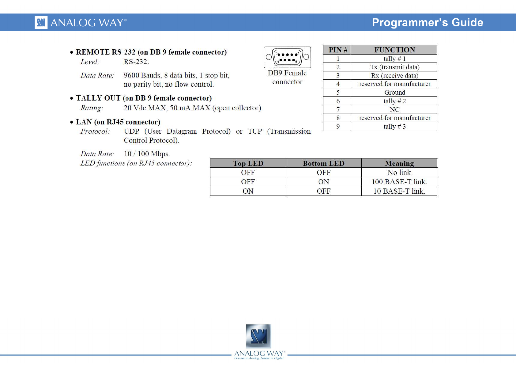
A5 COMMUNICATION PORTS
3
Page 4
4
Page 5

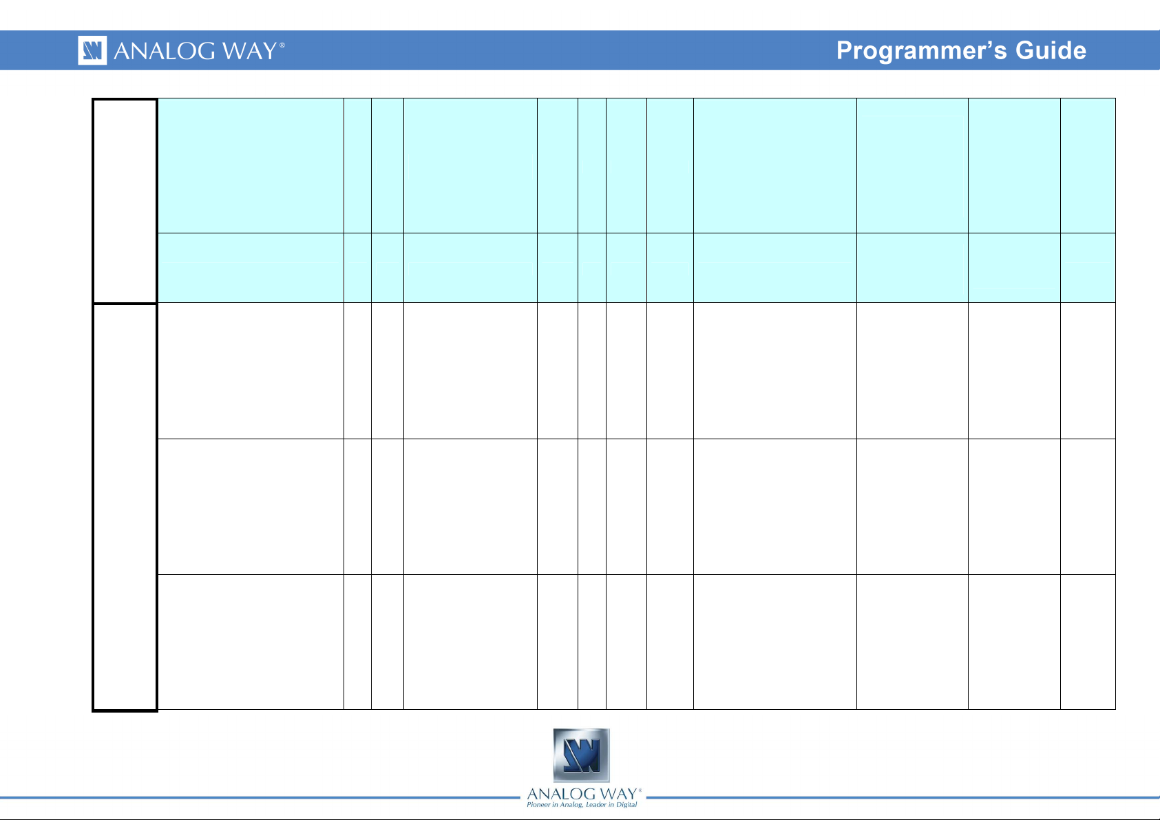
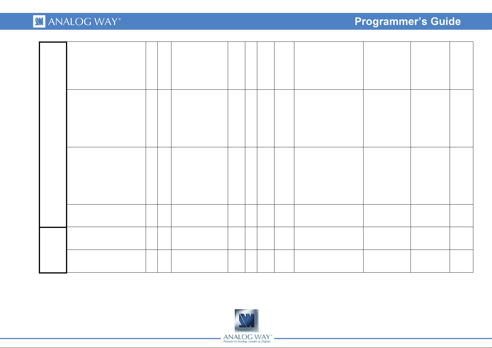
Group Name
DIESE # #
System
READY * *
DEV ? DEV
FACTORYRESET YR YR
POSMEMORYRESET YE YE
CSTORE YS YS
QUIET YQ YQ
LOCK YK YK
Controls
LCDBRIGHTNESS YB YB
KEYBRIGHTNESS Yb Yb
Command Description
Answer
Command
request to send all vars Rd/Wr 0 2 0
machine ready status Rd 0 1 0
device type Rd 71 72 71
factory settings (without
image settings)
erase image settings (bit
field)
storing (don't power-off) Rd 0 1 0
status out filtering Rd/Wr 0 1 0
device locking Rd/Wr 0 2 0
front panel display
brightness
front panel key
brightness
Read/
Write
Rd/Wr 0 1 0 (auto clear)
Rd/Wr 0 7 0
Rd/Wr 1 8 8
Rd/Wr 1 8 4
Min
Max
Default
Value
Value Index #1 Index #2 Index #3
0 = vars enumeration finished
1 = all vars enumeration
requested
2 = none default value vars
enumeration
0 = initializing,
1 = ready
71 = Diventix II
72 = Diventix LE
0 = None
1 = positioning & Cropping
2 = Colorimetry
4 = Hard
7 = all
0 = ready,
1 = storing
1 = remove input status
sending
0 = Not locked
1 = Menu Locked
2 = Front panel Locked
1..8 = brightness level, 12.5%
step
1..8 = brightness level, 12.5%
step
0 = None
1 = Auto centering
2 = Auto setting
COPKIND CK CK
COPPROGRESS CP CP
5
slow operation type Rd 0 7 0
slow operation progress Rd 0 100 0 0 up to 100%
3 = StandBy
4 = Logo Recording
5 = Factory setting
6 = Clear user settings
7 = Changing mode
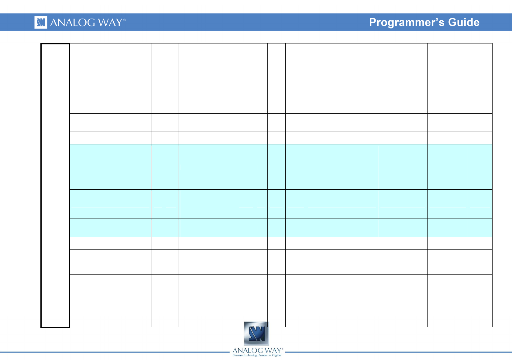
Page 6

0 = Mixer mode
SWITCHER_MODE CM CM
Device mode Rd/Wr 0 3 0
1 = Matrix mode
2 = Embedded softedge mode
3 = Synchronous Matrix mode
Version
AUTO_LOCK YL YL
AUTO_TAKE YT YT
AUTO_STEPBACK YA YA
AUTO_SET YX YX
BUTTON_1_1_MODE YM YM
NATIVE_ZOOM_REQUEST YY YY
HDCP_CONFLICT HC HC
BOOT_ERROR_STATUS BE BE
VERI1 xi xi
VERI2 xj xj
VERI3 xk xk
VERI4 xl xl
VERK xK xK
auto-lock (prevent from
no-signal selection)
auto-take Rd/Wr 0 1 0 1 = automatic TAKE enable
preset toggle Rd/Wr 0 1 0
inputs auto-setting Rd/Wr 0 1 0 (auto clear)
front panel key 1:1 mode Rd/Wr 0 1 1
current layer 1:1 scaling
request
HDCP conflict Rd 0 1 0
boot error notification (bit
field)
machine ID byte 0 & byte
1
machine ID byte 2 & byte
3
machine ID byte 4 & byte
5
machine ID byte 6 & byte
7
programmable
components checksum &
version
Rd/Wr 0 1 1
Rd/Wr 0 1 0 (auto clear)
Rd 0 65535 0 bit field, one bit per card
Rd 0 65535 0 ex : AAAA
Rd 0 65535 0 ex : AAAA
Rd 0 65535 0 ex : AAAA
Rd 0 65535 0 ex : AAAA
Rd 0 65535 0
1 = disable selection of inputs
without signal
1 = exchange Current and Next
presets on TAKE operation
0 = 1_1 key in no zoom mode
1 = 1_1 key in centered mode
1 = input HDCP content and at
least one output not HDCP
0 = components
number
1 =
microcontroler
0 = Micro
1 = In1
2 = In2
3 = Out
4 = Scaler
5 = Video
2 = 1st
FPGA/CPLD
3 = 2nd
FPGA/CPLD
4 = 3rd
FPGA/CPLD
5 = 4th
FPGA/CPLD
6 = 5th
FPGA/CPLD
7 = 6th
FPGA/CPLD
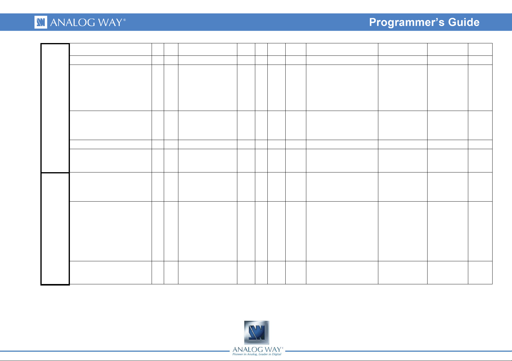
6
Page 7

0 = Micro
1 = In1
2 = In2
3 = Out
4 = Scaler
5 = Video
VERV xV xV
this commands set
version
Rd 0 65535
15
VERUPD xU xU
OPT yo yo
REV xR xR
Inputs IN_NOT_EXTENDED ix ix
upgrade version (bit
fields)
validated & detected
options
cards revisions Rd 0 255 0
multihead with covering
input source
Rd 0 65535 0
Rd 0 65535 0
Rd/Wr 0 1 0
bit 15 = 1 for BETA version,
bits 14 down to 0 for hexa
coded version number
ex: v4.00 = 0x400 = 1024
bit 0 = LAN installed
bit 1 = Video option installed
bit 2 = audio option installed
0 = monohead source splitted
on each machine
1 = multihead source with
covering management
0 = Micro
1 = In1
2 = In2
3 = Out
4 = Scaler
5 = Video
0 = Micro
1 = In1
2 = In2
3 = Out
4 = Scaler
5 = Video
0 = Input1
1 = Input2
2 = Input3
3 = Input4
4 = Input5
5 = Input6
6 = Input7
7 = Input8
0 = Analog Plug
1 = DVI Plug
2 = SDI Plug
7
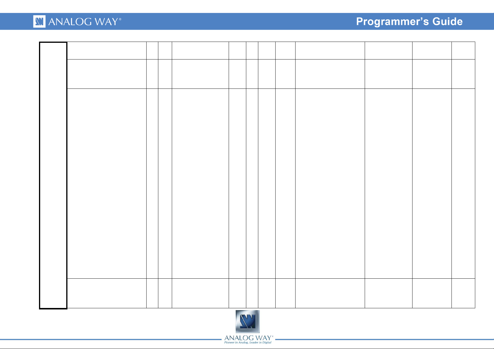
Page 8

0 = None
1 = Invalid
2 = unknown
3 = SDTV NTSC
4 = SDTV PAL
5 = SDTV SECAM
6 = SDTV BW
7 = SDTV 480i
8 = SDTV 576i
9 = EDTV 480p
10 = EDTV 576p
11 = HDTV 720p
12 = HDTV 1035i
13 = HDTV 1080i
14 = HDTV 1080p
15 = HDTV 1080sF
16 = CPU 640x480 VGA
IN_USR_FORMAT iU iU
user corrected input
format
Rd/Wr 0 41 0
17 = CPU 800x600 SVGA
18 = CPU 1024x768 XGA
19 = CPU 1280x960
20 = CPU 1280x1024 SXGA
21 = CPU 1364x1024 DILA 4/3
22 = CPU 1400x1050 SXGA+
23 = CPU 1600x900
24 = CPU 1600x1200 UXGA
25 = CPU 848x480 WVGA
26 = CPU 800x480
27 = CPU 1152x864
28 = CPU 720p RGB
29 = CPU 1280x768 WXGA
30 = CPU 1280x600
31 = CPU 1360x768 SWXGA
32 = CPU 1360x1024
33 = CPU 1366x800 SWXGA+
34 = CPU 1200x800
35 = CPU 1680x1050
WSXGA+
36 = CPU 1080p RGB
37 = CPU 1920x1200 WUXGA
38 = CPU 1920x1440
39 = CPU 1440x900
40 = CPU 2048x1080 2K 16/9
41 = CPU 1366x768
0 = Input1
1 = Input2
2 = Input3
3 = Input4
4 = Input5
5 = Input6
6 = Input7
7 = Input8
0 = Analog Plug
1 = DVI Plug
2 = SDI Plug
8
Page 9

0 = composite SDTV
1 = Y/C SDTV
2 = RGBS TTL/Analog
SDTV/EDTV/HDTV
3 = RGB SOG
SDTV/EDTV/HDTV
4 = YUV SDTV/EDTV/HDTV
5 = SOG Computer
6 = H&V or Composite
(TTL/Analog) Computer
IN_TYPE iK iK
input signal type Rd/Wr 0 17 13
7 = B&W Computer
8 = RGB 16-235 DVI-D
EDTV/HDTV
9 = YUV DVI-D EDTV/HDTV
10 = RGB 0-255 DVI-D
Computer
11 = RGB 16-235 DVI-D
Computer
12 = SDI SDTV/HDTV
13 = analog Computer,
separate H&V sync
14 = analog Computer, TTL
composite sync
15 = analog Computer, analog
composite sync
16 = analog video RGB, TTL
composite sync
17 = analog video RGB, analog
composite sync
0 = Input1
1 = Input2
2 = Input3
3 = Input4
4 = Input5
5 = Input6
6 = Input7
7 = Input8
0 = Analog Plug
1 = DVI Plug
2 = SDI Plug
0 = Input1
1 = Input2
IN_SYNC_LOAD il il
IN_USED iu iu
9
75 ohms analog H sync
load
used input Rd/Wr 0 1 1 0 = unused input
Rd/Wr 0 1 0
0 = High Z
1 = 75 ohms load
2 = Input3
3 = Input4
4 = Input5
5 = Input6
6 = Input7
7 = Input8
0 = Input1
1 = Input2
2 = Input3
3 = Input4
4 = Input5
5 = Input6
6 = Input7
7 = Input8
0 = Analog Plug
1 = DVI Plug
2 = SDI Plug
0 = Analog Plug
1 = DVI Plug
2 = SDI Plug
Page 10
IN_SD_STD iS iS
IN_CROPPING iC iC
IN_HDCP_ENABLE iH iH
IN_CROP_MODE im im
IN_REMAPPING iR iR
input video standard Rd/Wr 0 7 0
activate input finder for
cropping
enable DVI-D input
HDCP answer
input finder selection Rd/Wr 0 1 1
input processing pending Rd 0 1 0
Rd/Wr 0 1 0
Rd/Wr 0 1 1
0 = Auto
1 = NTSC (M,J)
2 = PAL (BDGHIN)
3 = PAL (M)
4 = PAL (M-Combination)
5 = NTSC 4.43
6 = SECAM
7 = PAL 60
0 = direct input cropping
1 = frame displayed to select
cropping zone
0 = Input1
1 = Input2
2 = Input3
3 = Input4
4 = Input5
5 = Input6
6 = Input7
7 = Input8
0 = Input1
1 = Input2
2 = Input3
3 = Input4
4 = Input5
5 = Input6
6 = Input7
7 = Input8
0 = Input1
1 = Input2
2 = Input3
3 = Input4
0 = No Input
1 = Input1 / Frame1
/ Logo1 /
MaskFrame1
2 = Input2 / Frame2
/ Logo2
3 = Input3 / Frame3
/ Logo3
4 = Input4 / Frame4
/ Logo4
5 = Input5 / Frame5
/ Logo5
6 = Input6 / Frame6
/ Logo6
7 = Input7 / Frame7
/ Logo7
8 = Input8 / Frame8
/ Logo8
0 = Analog Plug
1 = DVI Plug
2 = SDI Plug
0 = Analog Plug
1 = DVI Plug
2 = SDI Plug
10
Page 11

0 = 640x480 VGA
1 = 800x600 SVGA
2 = 1024x768 XGA
3 = 1280x960
4 = 1280x1024 SXGA
5 = 1364x1024 4/3 DILA
EDID
EDID_FORMAT EF EF
EDID_RATE ER ER
EDID preferred format Rd/Wr 0 20 20
EDID preferred frame
frequency
Rd/Wr 6 10 8
6 = 1400x1050 SXGA+
7 = 1600x1200 UXGA
8 = 852x480 WVGA
9 = 720pRGB
10 = 1280x768 WXGA
11 = 1360x768 SWXGA
12 = 1366x800 SWXGA+
13 = 1200x800 RGB
14 = 1680x1050 WSXGA+
15 = 1080pRGB
16 = 1440x900 RGB
17 = 1920x1200 WUXGA
18 = 2048x1080 2K
19 = 1366x768
20 = Custom
0 = Custom Field Rate
1 = 23,97 Hz
2 = 24 Hz
3 = 25 Hz
4 = 29,97 Hz
5 = 30 Hz
6 = 50 Hz
7 = 59,94 Hz
8 = 60 Hz
9 = 72 Hz
10 = 75 Hz
0 = Input1
1 = Input2
2 = Input3
3 = Input4
4 = Input5
5 = Input6
6 = Input7
7 = Input8
0 = Input1
1 = Input2
2 = Input3
3 = Input4
4 = Input5
5 = Input6
6 = Input7
7 = Input8
0 = Analog Plug
1 = DVI Plug
2 = SDI Plug
0 = Analog Plug
1 = DVI Plug
2 = SDI Plug
0 = Input1
1 = Input2
Input
status
11
SIG_HPOL sh sh
input H sync polarity Rd 0 0 0
0 = Negative Sync
1 = Positive Sync
2 = Input3
3 = Input4
4 = Input5
5 = Input6
6 = Input7
7 = Input8
0 = Analog Plug
1 = DVI Plug
2 = SDI Plug
Page 12
0 = Input1
1 = Input2
SIG_VPOL sv sv
SIG_SYNC_TYPE sK sK
SIG_FREQ_FIELD sf sf
input V sync polarity Rd 0 1 0
input sync type Rd 0 3 0
input frame frequency Rd 0 65535 0
0 = Negative Sync
1 = Positive Sync
0 = H&V Sync
1 = TTL Composite Sync
2 = Analog composite Sync
3 = Synchro on green (SOG)
frame frequency in 1/100 Hz
unit
2 = Input3
3 = Input4
4 = Input5
5 = Input6
6 = Input7
7 = Input8
0 = Input1
1 = Input2
2 = Input3
3 = Input4
4 = Input5
5 = Input6
6 = Input7
7 = Input8
0 = Input1
1 = Input2
2 = Input3
3 = Input4
4 = Input5
5 = Input6
6 = Input7
7 = Input8
0 = Analog Plug
1 = DVI Plug
2 = SDI Plug
0 = Analog Plug
1 = DVI Plug
2 = SDI Plug
0 = Analog Plug
1 = DVI Plug
2 = SDI Plug
0 = Input1
1 = Input2
2 = Input3
SIG_FREQ_LINE sl sl
12
input line frequency Rd 0 65535 0 line frequency in x100 Hz unit
3 = Input4
4 = Input5
5 = Input6
6 = Input7
7 = Input8
0 = Analog Plug
1 = DVI Plug
2 = SDI Plug
Page 13
0 = Input1
1 = Input2
SIG_COMPLETE sc sc
input scan complete Rd 0 1 0
1 = input scan operations
complete
2 = Input3
3 = Input4
4 = Input5
5 = Input6
6 = Input7
7 = Input8
0 = Analog Plug
1 = DVI Plug
2 = SDI Plug
13
Page 14

0 = None
1 = Invalid
2 = unknown
3 = SDTV NTSC
4 = SDTV PAL
5 = SDTV SECAM
6 = SDTV BW
7 = SDTV 480i
8 = SDTV 576i
9 = EDTV 480p
10 = EDTV 576p
11 = HDTV 720p
12 = HDTV 1035i
13 = HDTV 1080i
14 = HDTV 1080p
15 = HDTV 1080sF
16 = CPU 640x480 VGA
SIG_DETECTED_FORMAT sD sD
detected input format
name
Rd 0 41 0
17 = CPU 800x600 SVGA
18 = CPU 1024x768 XGA
19 = CPU 1280x960
20 = CPU 1280x1024 SXGA
21 = CPU 1364x1024 DILA 4/3
22 = CPU 1400x1050 SXGA+
23 = CPU 1600x900
24 = CPU 1600x1200 UXGA
25 = CPU 848x480 WVGA
26 = CPU 800x480
27 = CPU 1152x864
28 = CPU 720p RGB
29 = CPU 1280x768 WXGA
30 = CPU 1280x600
31 = CPU 1360x768 SWXGA
32 = CPU 1360x1024
33 = CPU 1366x800 SWXGA+
34 = CPU 1200x800
35 = CPU 1680x1050
WSXGA+
36 = CPU 1080p RGB
37 = CPU 1920x1200 WUXGA
38 = CPU 1920x1440
39 = CPU 1440x900
40 = CPU 2048x1080 2K 16/9
41 = CPU 1366x768
0 = Input1
1 = Input2
2 = Input3
3 = Input4
4 = Input5
5 = Input6
6 = Input7
7 = Input8
0 = Analog Plug
1 = DVI Plug
2 = SDI Plug
14
Page 15

0 = bit0
to bit7
slice
1 = bit8
to bit15
slice
2 = bit16
to bit23
slice
3 = bit24
to bit31
slice
4 = bit32
to bit39
slice
5 = bit40
to bit47
slice
SIG_FORMAT_LIST sL sL
SIG_SCANTYPE ss ss
compatible detected
formats list (bit field)
input scan type Rd 0 3 0
Rd 0 255 0
bit field, one bit per input
format name
0 = Progressive
1 = Interlaced, Top field first
2 = Interlaced, Bottom field first
3 = Segmented frame
0 = Input1
1 = Input2
2 = Input3
3 = Input4
4 = Input5
5 = Input6
6 = Input7
7 = Input8
0 = Input1
1 = Input2
2 = Input3
3 = Input4
4 = Input5
5 = Input6
6 = Input7
7 = Input8
0 = Analog Plug
1 = DVI Plug
2 = SDI Plug
0 = Analog Plug
1 = DVI Plug
2 = SDI Plug
0 = Input1
1 = Input2
SIG_WIDTH sw sw
SIG_SLOTNUMBER sN sN
15
displayable input pixel
count
input settings memory
slot number
Rd 0 65535 0 Unit : pixels
Rd 0 40 40
0 up to 39 = slot number,
40 = no slot
2 = Input3
3 = Input4
4 = Input5
5 = Input6
6 = Input7
7 = Input8
0 = Input1
1 = Input2
2 = Input3
3 = Input4
4 = Input5
5 = Input6
6 = Input7
7 = Input8
0 = Analog Plug
1 = DVI Plug
2 = SDI Plug
0 = Analog Plug
1 = DVI Plug
2 = SDI Plug
Page 16
0 = Input1
1 = Input2
SIG_HEIGHT st st
displayable input line
count
Rd 0 65535 0 Unit : pixels
2 = Input3
3 = Input4
4 = Input5
5 = Input6
6 = Input7
7 = Input8
0 = Analog Plug
1 = DVI Plug
2 = SDI Plug
Input
Settings
SIG_HDCP sn sn
SET_DEFAULT SK SK
SET_HPOS SH SH
SET_VPOS SV SV
HDCP input status Rd 0 1 0 1 = HDCP content
0 = None
current input default
settings (auto clear)
input signal horizontal
position
input signal vertical
position
Rd/Wr 0 7 0
Rd/Wr 0 2048 1024 1024 = neutral
Rd/Wr 0 2048 1024 1024 = neutral
1 = positioning & Cropping
2 = Colorimetry
4 = Hard
7 = all
0 = Input1
1 = Input2
2 = Input3
3 = Input4
0 = Input1
1 = Input2
2 = Input3
3 = Input4
4 = Input5
5 = Input6
6 = Input7
7 = Input8
0 = Input1
1 = Input2
2 = Input3
3 = Input4
4 = Input5
5 = Input6
6 = Input7
7 = Input8
0 = Input1
1 = Input2
2 = Input3
3 = Input4
4 = Input5
5 = Input6
6 = Input7
7 = Input8
0 = Analog Plug
1 = DVI Plug
2 = SDI Plug
0 = Analog Plug
1 = DVI Plug
2 = SDI Plug
0 = Analog Plug
1 = DVI Plug
2 = SDI Plug
0 = Analog Plug
1 = DVI Plug
2 = SDI Plug
16
Page 17

0 = Input1
1 = Input2
SET_HSIZE Sw Sw
SET_VSIZE Sh Sh
SET_BRIGHTNESS Sg Sg
input signal horizontal
size
input signal vertical size Rd/Wr 0 4096 2048 2048 = neutral
input signal brightness Rd/Wr 0 255 128 128 = neutral
Rd/Wr 0 4096 2048 2048 = neutral
2 = Input3
3 = Input4
4 = Input5
5 = Input6
6 = Input7
7 = Input8
0 = Input1
1 = Input2
2 = Input3
3 = Input4
4 = Input5
5 = Input6
6 = Input7
7 = Input8
0 = Input1
1 = Input2
2 = Input3
3 = Input4
4 = Input5
5 = Input6
6 = Input7
7 = Input8
0 = Analog Plug
1 = DVI Plug
2 = SDI Plug
0 = Analog Plug
1 = DVI Plug
2 = SDI Plug
0 = Analog Plug
1 = DVI Plug
2 = SDI Plug
0 = Input1
1 = Input2
2 = Input3
SET_CONTRAST Sc Sc
17
input signal contrast Rd/Wr 0 255 128 128 = neutral
3 = Input4
4 = Input5
5 = Input6
6 = Input7
7 = Input8
0 = Analog Plug
1 = DVI Plug
2 = SDI Plug
Page 18

0 = Input1
1 = Input2
SET_COLOR Sr Sr
SET_HUE Su Su
SET_HTOTAL ST ST
input signal color level Rd/Wr 0 255 128 128 = neutral
input signal hue (NTSC
only)
input signal total pixel
per line
Rd/Wr 0 255 128 128 = neutral
Rd/Wr 200 65535 200 Unit : pixels
2 = Input3
3 = Input4
4 = Input5
5 = Input6
6 = Input7
7 = Input8
0 = Input1
1 = Input2
2 = Input3
3 = Input4
4 = Input5
5 = Input6
6 = Input7
7 = Input8
0 = Input1
1 = Input2
2 = Input3
3 = Input4
4 = Input5
5 = Input6
6 = Input7
7 = Input8
0 = Analog Plug
1 = DVI Plug
2 = SDI Plug
0 = Analog Plug
1 = DVI Plug
2 = SDI Plug
0 = Analog Plug
1 = DVI Plug
2 = SDI Plug
0 = Input1
1 = Input2
SET_HTOTALMAXI SX SX
18
input signal maximum
total pixel per line
Rd 200 65535 200 Unit : pixels
2 = Input3
3 = Input4
4 = Input5
5 = Input6
6 = Input7
7 = Input8
0 = Analog Plug
1 = DVI Plug
2 = SDI Plug
Page 19

0 = Input1
1 = Input2
SET_PHASE SS SS
SET_AUTOCAD Sa Sa
SET_USER_GAIN_R sr sr
input signal phase Rd/Wr 0 63 0 2 pixels range phase
input signal
autocentering
ADC R channel
adjustment (advanced
setting)
Rd/Wr 0 1 0 (auto clear)
Rd/Wr 0 255 128 128 = neutral
2 = Input3
3 = Input4
4 = Input5
5 = Input6
6 = Input7
7 = Input8
0 = Input1
1 = Input2
2 = Input3
3 = Input4
4 = Input5
5 = Input6
6 = Input7
7 = Input8
0 = Input1
1 = Input2
2 = Input3
3 = Input4
4 = Input5
5 = Input6
6 = Input7
7 = Input8
0 = Analog Plug
1 = DVI Plug
2 = SDI Plug
0 = Analog Plug
1 = DVI Plug
2 = SDI Plug
0 = Analog Plug
1 = DVI Plug
2 = SDI Plug
0 = Input1
1 = Input2
SET_USER_GAIN_G sg sg
19
ADC G channel
adjustment (advanced
setting)
Rd/Wr 0 255 128 128 = neutral
2 = Input3
3 = Input4
4 = Input5
5 = Input6
6 = Input7
7 = Input8
0 = Analog Plug
1 = DVI Plug
2 = SDI Plug
Page 20

0 = Input1
1 = Input2
2 = Input3
3 = Input4
4 = Input5
5 = Input6
6 = Input7
7 = Input8
0 = Input1
1 = Input2
2 = Input3
3 = Input4
4 = Input5
5 = Input6
6 = Input7
7 = Input8
0 = Input1
1 = Input2
2 = Input3
3 = Input4
4 = Input5
5 = Input6
6 = Input7
7 = Input8
0 = Analog Plug
1 = DVI Plug
2 = SDI Plug
0 = Analog Plug
1 = DVI Plug
2 = SDI Plug
0 = Analog Plug
1 = DVI Plug
2 = SDI Plug
SET_USER_GAIN_B sb sb
SET_PULLDOWN_2_2 Sn Sn
SET_PULLDOWN_3_2 Sp Sp
ADC B channel
adjustment (advanced
setting)
2:2 pulldown Rd/Wr 0 1 1
3:2 pulldown Rd/Wr 0 1 1
Rd/Wr 0 255 128 128 = neutral
0 = Disabled
1 = Automatic detection
0 = Disabled
1 = Automatic detection
0 = Native, full screen
1 = LetterBox 1.78, 4/3 with
16/9 content and black bands
SET_ASPECT_RATIO_IN sA sA
20
input picture aspect ratio Rd/Wr 0 4 0
2 = LetterBox 2.35, 4/3 with
2,35 content and black bands
3 = PillarBox, 16/9 with 4/3
content and black bands
4 = Anamorphic, 4/3 with 16/9
content without black bands
0 = Input1
1 = Input2
2 = Input3
3 = Input4
4 = Input5
5 = Input6
6 = Input7
7 = Input8
0 = Analog Plug
1 = DVI Plug
2 = SDI Plug
Page 21
SET_ASPECT_RATIO_OUT sB sB
SET_OVER_SCAN so so
SET_CROP_HSTART Lh Lh
0 = 1:1, not distorted, no zoom,
black bands or cropped
output picture aspect
ratio
overscan Rd/Wr 0 1 1 0 = underscan, 1 = overscan
input signal H cropping
start
Rd/Wr 0 3 2
Rd/Wr 0 2048 0 0 = 0% = no left cropping
1 = centered, not distorted,
black bands added
2 = full screen, distorted, input
aspect ratio not preserved
3 = cropped, not distorted,
without black bands
0 = Input1
1 = Input2
2 = Input3
3 = Input4
4 = Input5
5 = Input6
6 = Input7
7 = Input8
0 = Input1
1 = Input2
2 = Input3
3 = Input4
4 = Input5
5 = Input6
6 = Input7
7 = Input8
0 = Input1
1 = Input2
2 = Input3
3 = Input4
4 = Input5
5 = Input6
6 = Input7
7 = Input8
0 = Analog Plug
1 = DVI Plug
2 = SDI Plug
0 = Analog Plug
1 = DVI Plug
2 = SDI Plug
0 = Analog Plug
1 = DVI Plug
2 = SDI Plug
0 = Input1
1 = Input2
SET_CROP_VSTART Lv Lv
21
input signal V cropping
start
Rd/Wr 0 2048 0 0 = 0% = no top cropping
2 = Input3
3 = Input4
4 = Input5
5 = Input6
6 = Input7
7 = Input8
0 = Analog Plug
1 = DVI Plug
2 = SDI Plug
Page 22

0 = Input1
1 = Input2
SET_CROP_HEND LH LH
SET_CROP_VEND LV LV
SET_FORCE_TO_4_3 Lf Lf
input signal H cropping
end
input signal V cropping
end
force 4/3 aspect ratio
(SDTV only)
Rd/Wr 0 2048 2048
Rd/Wr 0 2048 2048 2048 = 100% = no top cropping
Rd/Wr 0 1 0
2048 = 100% = no right
cropping
1 = force to 4/3 aspect ratio
(SDTV only)
2 = Input3
3 = Input4
4 = Input5
5 = Input6
6 = Input7
7 = Input8
0 = Input1
1 = Input2
2 = Input3
3 = Input4
4 = Input5
5 = Input6
6 = Input7
7 = Input8
0 = Input1
1 = Input2
2 = Input3
3 = Input4
4 = Input5
5 = Input6
6 = Input7
7 = Input8
0 = Analog Plug
1 = DVI Plug
2 = SDI Plug
0 = Analog Plug
1 = DVI Plug
2 = SDI Plug
0 = Analog Plug
1 = DVI Plug
2 = SDI Plug
0 = Input1
1 = Input2
SET_MOTION_DETECT Sm Sm
22
Defines moving pixels
detection threshold
Rd/Wr 0 60 0
60 = standard setting, 10 =
typical camera setting
2 = Input3
3 = Input4
4 = Input5
5 = Input6
6 = Input7
7 = Input8
0 = full
deinterlacing
60 = standard
deinterlacing
Page 23
Preset
Elements
PE_INPUTNUM IN IN
PE_SOURCENUM IS IS
PE_ID pI pI
PE_NEW_ID pN pN
0 = No Input
1 = Input1 / Frame1 / Logo1 /
MaskFrame1
displayed input number
or frame number or logo
number
source number Rd/Wr 0 64 0 ARC/ORC source number
unique layer identifier
number
force a new unique layer
identifier number
Rd/Wr 0 8 0
Rd 0 16 0 computed layer identifier
Rd/Wr 0 1 0
2 = Input2 / Frame2 / Logo2
3 = Input3 / Frame3 / Logo3
4 = Input4 / Frame4 / Logo4
5 = Input5 / Frame5 / Logo5
6 = Input6 / Frame6 / Logo6
7 = Input7 / Frame7 / Logo7
8 = Input8 / Frame8 / Logo8
0 = Current Preset
1 = Next Preset
2 = Previous Preset
3 = Memorized
Preset 1
4 = Memorized
Preset 2
5 = Memorized
Preset 3
6 = Memorized
Preset 4
0 = Current Preset
1 = Next Preset
2 = Previous Preset
3 = Memorized
Preset 1
4 = Memorized
Preset 2
5 = Memorized
Preset 3
6 = Memorized
Preset 4
0 = Current Preset
1 = Next Preset
2 = Previous Preset
3 = Memorized
Preset 1
4 = Memorized
Preset 2
5 = Memorized
Preset 3
6 = Memorized
Preset 4
0 = Current Preset
1 = Next Preset
2 = Previous Preset
3 = Memorized
Preset 1
4 = Memorized
Preset 2
5 = Memorized
Preset 3
6 = Memorized
Preset 4
0 = Background
Frame
1 = Layer A
2 = Layer B
3 = Layer C
4 = Layer D
5 = Logo A
6 = Logo B
7 = Frame Mask
0 = Background
Frame
1 = Layer A
2 = Layer B
3 = Layer C
4 = Layer D
5 = Logo A
6 = Logo B
7 = Frame Mask
0 = Background
Frame
1 = Layer A
2 = Layer B
3 = Layer C
4 = Layer D
5 = Logo A
6 = Logo B
7 = Frame Mask
0 = Background
Frame
1 = Layer A
2 = Layer B
3 = Layer C
4 = Layer D
5 = Logo A
6 = Logo B
7 = Frame Mask
23
Page 24

0 = Current Preset
PE_POS_H pH pH
PE_POS_V pV pV
PE_SIZE_H pW pW
PE_SIZE_V pS pS
layer left H position on
output screen
layer top V position on
output screen
layer H size on output
screen (without borders)
layer V size on output
screen (without borders)
Rd/Wr 0 65535 32768
Rd/Wr 0 65535 32768
Rd/Wr 0 65535 32768 in pixel
Rd/Wr 0 65535 32768 in pixel
in pixel with 32768 offset
(32768 = left side, visible)
in pixel with 32768 offset
(32768 = top side, visible)
1 = Next Preset
2 = Previous Preset
3 = Memorized
Preset 1
4 = Memorized
Preset 2
5 = Memorized
Preset 3
6 = Memorized
Preset 4
0 = Current Preset
1 = Next Preset
2 = Previous Preset
3 = Memorized
Preset 1
4 = Memorized
Preset 2
5 = Memorized
Preset 3
6 = Memorized
Preset 4
0 = Current Preset
1 = Next Preset
2 = Previous Preset
3 = Memorized
Preset 1
4 = Memorized
Preset 2
5 = Memorized
Preset 3
6 = Memorized
Preset 4
0 = Current Preset
1 = Next Preset
2 = Previous Preset
3 = Memorized
Preset 1
4 = Memorized
Preset 2
5 = Memorized
Preset 3
6 = Memorized
Preset 4
0 = Background
Frame
1 = Layer A
2 = Layer B
3 = Layer C
4 = Layer D
5 = Logo A
6 = Logo B
7 = Frame Mask
0 = Background
Frame
1 = Layer A
2 = Layer B
3 = Layer C
4 = Layer D
5 = Logo A
6 = Logo B
7 = Frame Mask
0 = Background
Frame
1 = Layer A
2 = Layer B
3 = Layer C
4 = Layer D
5 = Logo A
6 = Logo B
7 = Frame Mask
0 = Background
Frame
1 = Layer A
2 = Layer B
3 = Layer C
4 = Layer D
5 = Logo A
6 = Logo B
7 = Frame Mask
24
Page 25

0 = Current Preset
PE_CROP_WIN_POS_H CH CH
PE_CROP_WIN_POS_V CV CV
PE_CROP_WIN_SIZE_H CW CW
PE_CROP_WIN_SIZE_V CS CS
layer cropping H position Rd/Wr 0 65535 32768
layer cropping V position Rd/Wr 0 65535 32768
layer H cropping size Rd/Wr 0 58981 0 in % (65535 = 100%)
layer V cropping size Rd/Wr 0 58981 0 in % (65535 = 100%)
in % (65535 = 100% = full left
cropping)
in % (65535 = 100% = full top
cropping)
1 = Next Preset
2 = Previous Preset
3 = Memorized
Preset 1
4 = Memorized
Preset 2
5 = Memorized
Preset 3
6 = Memorized
Preset 4
0 = Current Preset
1 = Next Preset
2 = Previous Preset
3 = Memorized
Preset 1
4 = Memorized
Preset 2
5 = Memorized
Preset 3
6 = Memorized
Preset 4
0 = Current Preset
1 = Next Preset
2 = Previous Preset
3 = Memorized
Preset 1
4 = Memorized
Preset 2
5 = Memorized
Preset 3
6 = Memorized
Preset 4
0 = Current Preset
1 = Next Preset
2 = Previous Preset
3 = Memorized
Preset 1
4 = Memorized
Preset 2
5 = Memorized
Preset 3
6 = Memorized
Preset 4
0 = Background
Frame
1 = Layer A
2 = Layer B
3 = Layer C
4 = Layer D
5 = Logo A
6 = Logo B
7 = Frame Mask
0 = Background
Frame
1 = Layer A
2 = Layer B
3 = Layer C
4 = Layer D
5 = Logo A
6 = Logo B
7 = Frame Mask
0 = Background
Frame
1 = Layer A
2 = Layer B
3 = Layer C
4 = Layer D
5 = Logo A
6 = Logo B
7 = Frame Mask
0 = Background
Frame
1 = Layer A
2 = Layer B
3 = Layer C
4 = Layer D
5 = Logo A
6 = Logo B
7 = Frame Mask
25
Page 26

0 = Current Preset
PE_ALPHA pA pA
PE_BORDER_STYLE bS bS
PE_BORDER_COLOR bC bC
PE_BORDER_ALPHA bA bA
layer transparency Rd/Wr 0 255 0
border style Rd/Wr 0 4 0
border color Rd/Wr 0 544 0 color number
border transparency Rd/Wr 0 255 128 255 = full transparency
0 = opaque, 255 = 100% = full
transparency
0 = No Border
1 = Edges
2 = Smooth
3 = Shadow
4 = Smooth shadow
1 = Next Preset
2 = Previous Preset
3 = Memorized
Preset 1
4 = Memorized
Preset 2
5 = Memorized
Preset 3
6 = Memorized
Preset 4
0 = Current Preset
1 = Next Preset
2 = Previous Preset
3 = Memorized
Preset 1
4 = Memorized
Preset 2
5 = Memorized
Preset 3
6 = Memorized
Preset 4
0 = Current Preset
1 = Next Preset
2 = Previous Preset
3 = Memorized
Preset 1
4 = Memorized
Preset 2
5 = Memorized
Preset 3
6 = Memorized
Preset 4
0 = Current Preset
1 = Next Preset
2 = Previous Preset
3 = Memorized
Preset 1
4 = Memorized
Preset 2
5 = Memorized
Preset 3
6 = Memorized
Preset 4
0 = Background
Frame
1 = Layer A
2 = Layer B
3 = Layer C
4 = Layer D
5 = Logo A
6 = Logo B
7 = Frame Mask
0 = Background
Frame
1 = Layer A
2 = Layer B
3 = Layer C
4 = Layer D
5 = Logo A
6 = Logo B
7 = Frame Mask
0 = Background
Frame
1 = Layer A
2 = Layer B
3 = Layer C
4 = Layer D
5 = Logo A
6 = Logo B
7 = Frame Mask
0 = Background
Frame
1 = Layer A
2 = Layer B
3 = Layer C
4 = Layer D
5 = Logo A
6 = Logo B
7 = Frame Mask
26
Page 27

0 = Current Preset
PE_BORDER_SIZE_H bH bH
PE_BORDER_SIZE_V bV bV
PE_BORDER_SHADOW_POS bP bP
PE_OPENING_TRANSITION oT oT
border H size Rd/Wr 0 127 10 in pixel
border V size Rd/Wr 0 127 10 in pixel
0 = SE = Bottom Right
layer shadow position Rd/Wr 0 3 0
layer opening transition Rd/Wr 0 2 1
1 = SW = Bottom Left
2 = NW = TOP Left
3 = NE = TOP Right
0 = Cut Transition
1 = Fade Transition
2 = Slide Transition
1 = Next Preset
2 = Previous Preset
3 = Memorized
Preset 1
4 = Memorized
Preset 2
5 = Memorized
Preset 3
6 = Memorized
Preset 4
0 = Current Preset
1 = Next Preset
2 = Previous Preset
3 = Memorized
Preset 1
4 = Memorized
Preset 2
5 = Memorized
Preset 3
6 = Memorized
Preset 4
0 = Current Preset
1 = Next Preset
2 = Previous Preset
3 = Memorized
Preset 1
4 = Memorized
Preset 2
5 = Memorized
Preset 3
6 = Memorized
Preset 4
0 = Current Preset
1 = Next Preset
2 = Previous Preset
3 = Memorized
Preset 1
4 = Memorized
Preset 2
5 = Memorized
Preset 3
6 = Memorized
Preset 4
0 = Background
Frame
1 = Layer A
2 = Layer B
3 = Layer C
4 = Layer D
5 = Logo A
6 = Logo B
7 = Frame Mask
0 = Background
Frame
1 = Layer A
2 = Layer B
3 = Layer C
4 = Layer D
5 = Logo A
6 = Logo B
7 = Frame Mask
0 = Background
Frame
1 = Layer A
2 = Layer B
3 = Layer C
4 = Layer D
5 = Logo A
6 = Logo B
7 = Frame Mask
0 = Background
Frame
1 = Layer A
2 = Layer B
3 = Layer C
4 = Layer D
5 = Logo A
6 = Logo B
7 = Frame Mask
27
Page 28
0 = Current Preset
PE_OPENING_TRANSITION_WAY oW oW
PE_OPENING_DURATION oD oD
PE_CLOSING_TRANSITION cT cT
PE_CLOSING_TRANSITION_WAY cW cW
opening transition
direction
opening transition time Rd/Wr 0 255 10
layer closing transition Rd/Wr 0 2 1
closing transition
direction
Rd/Wr 0 3 0
Rd/Wr 0 3 1
0 = Left to right Transition
1 = Right to left Transition
2 = Bottom to top Transition
3 = Top to bottom Transition
in 1/10 second (ex : 105 =
10.5s)
0 = Cut Transition
1 = Fade Transition
2 = Slide Transition
0 = Left to right Transition
1 = Right to left Transition
2 = Bottom to top Transition
3 = Top to bottom Transition
1 = Next Preset
2 = Previous Preset
3 = Memorized
Preset 1
4 = Memorized
Preset 2
5 = Memorized
Preset 3
6 = Memorized
Preset 4
0 = Current Preset
1 = Next Preset
2 = Previous Preset
3 = Memorized
Preset 1
4 = Memorized
Preset 2
5 = Memorized
Preset 3
6 = Memorized
Preset 4
0 = Current Preset
1 = Next Preset
2 = Previous Preset
3 = Memorized
Preset 1
4 = Memorized
Preset 2
5 = Memorized
Preset 3
6 = Memorized
Preset 4
0 = Current Preset
1 = Next Preset
2 = Previous Preset
3 = Memorized
Preset 1
4 = Memorized
Preset 2
5 = Memorized
Preset 3
6 = Memorized
Preset 4
0 = Background
Frame
1 = Layer A
2 = Layer B
3 = Layer C
4 = Layer D
5 = Logo A
6 = Logo B
7 = Frame Mask
0 = Background
Frame
1 = Layer A
2 = Layer B
3 = Layer C
4 = Layer D
5 = Logo A
6 = Logo B
7 = Frame Mask
0 = Background
Frame
1 = Layer A
2 = Layer B
3 = Layer C
4 = Layer D
5 = Logo A
6 = Logo B
7 = Frame Mask
0 = Background
Frame
1 = Layer A
2 = Layer B
3 = Layer C
4 = Layer D
5 = Logo A
6 = Logo B
7 = Frame Mask
28
Page 29

0 = Current Preset
Presets
PE_CLOSING_DURATION cD cD
PE_FREEZE_INPUT pZ pZ
P_PLUGNUM IP IP
P_KEYING_ENABLE KE KE
closing transition time Rd/Wr 0 255 10
input image freeze Rd/Wr 0 1 0 1 = input freeze
active plug on input Rd/Wr 0 2 0
keying/titling enable Rd/Wr 0 1 0 1 = enable keying/tiling
in 1/10 second (ex : 105 =
10.5s)
0 = Analog Plug
1 = DVI Plug
2 = SDI Plug
1 = Next Preset
2 = Previous Preset
3 = Memorized
Preset 1
4 = Memorized
Preset 2
5 = Memorized
Preset 3
6 = Memorized
Preset 4
0 = Current Preset
1 = Next Preset
2 = Previous Preset
3 = Memorized
Preset 1
4 = Memorized
Preset 2
5 = Memorized
Preset 3
6 = Memorized
Preset 4
0 = Current Preset
1 = Next Preset
2 = Previous Preset
3 = Memorized
Preset 1
4 = Memorized
Preset 2
5 = Memorized
Preset 3
6 = Memorized
Preset 4
0 = Current Preset
1 = Next Preset
2 = Previous Preset
3 = Memorized
Preset 1
4 = Memorized
Preset 2
5 = Memorized
Preset 3
6 = Memorized
Preset 4
0 = Background
Frame
1 = Layer A
2 = Layer B
3 = Layer C
4 = Layer D
5 = Logo A
6 = Logo B
7 = Frame Mask
0 = Background
Frame
1 = Layer A
2 = Layer B
3 = Layer C
4 = Layer D
5 = Logo A
6 = Logo B
7 = Frame Mask
0 = Input1
1 = Input2
2 = Input3
3 = Input4
4 = Input5
5 = Input6
6 = Input7
7 = Input8
29
Page 30

0 = Current Preset
1 = Next Preset
2 = Previous Preset
3 = Memorized
Preset 1
4 = Memorized
Preset 2
5 = Memorized
Preset 3
6 = Memorized
Preset 4
0 = Current Preset
1 = Next Preset
2 = Previous Preset
3 = Memorized
Preset 1
4 = Memorized
Preset 2
5 = Memorized
Preset 3
6 = Memorized
Preset 4
0 = Current Preset
1 = Next Preset
2 = Previous Preset
3 = Memorized
Preset 1
4 = Memorized
Preset 2
5 = Memorized
Preset 3
6 = Memorized
Preset 4
0 = Current Preset
1 = Next Preset
2 = Previous Preset
3 = Memorized
Preset 1
4 = Memorized
Preset 2
5 = Memorized
Preset 3
6 = Memorized
Preset 4
P_KEYING_LAYER KL KL
P_KEYING_TYPE KT KT
P_KEYING_SHADOW KS KS
P_KEYING_R_LEVEL KR KR
1 = Layer A
keying layer Rd/Wr 1 4 2
keying type Rd/Wr 0 3 3
shadow level under titling
layer
keying red level Rd/Wr 0 255 0 0 = 0%, 255 = 100%
Rd/Wr 0 255 0
2 = Layer B
3 = Layer C
4 = Layer D
0 = Luma titling
1 = Chroma titling
2 = luma keying
3 = chroma keying
0 = 0% = background
attenuated,
255 = 100% = black
background
30
Page 31

0 = Current Preset
1 = Next Preset
2 = Previous Preset
3 = Memorized
P_KEYING_G_LEVEL KG KG
P_KEYING_B_LEVEL KB KB
P_KEYING_TOLER KH KH
P_KEYING_INV Ki Ki
keying green level or
luma level
keying blue level Rd/Wr 0 255 0 0 = 0%, 255 = 100%
keying tolerance Rd/Wr 0 255 16 0 = 0%, 255 = 100%
key invert Rd/Wr 0 1 0 1 = invert key (inside keying)
Rd/Wr 0 255 255 0 = 0%, 255 = 100%
Preset 1
4 = Memorized
Preset 2
5 = Memorized
Preset 3
6 = Memorized
Preset 4
0 = Current Preset
1 = Next Preset
2 = Previous Preset
3 = Memorized
Preset 1
4 = Memorized
Preset 2
5 = Memorized
Preset 3
6 = Memorized
Preset 4
0 = Current Preset
1 = Next Preset
2 = Previous Preset
3 = Memorized
Preset 1
4 = Memorized
Preset 2
5 = Memorized
Preset 3
6 = Memorized
Preset 4
0 = Current Preset
1 = Next Preset
2 = Previous Preset
3 = Memorized
Preset 1
4 = Memorized
Preset 2
5 = Memorized
Preset 3
6 = Memorized
Preset 4
31
Page 32

0 = Current Preset
1 = Next Preset
2 = Previous Preset
3 = Memorized
P_KEYING_GRAB_ENABLE Kg Kg
P_KEYING_GRAB_H Kh Kh
P_KEYING_GRAB_V Kv Kv
P_KEYING_GRAB_GET Kc Kc
keying grabber mode Rd/Wr 0 1 0 1 = grabber enable
keying grabber H
position
keying grabber V
position
keying grabber enable Rd/Wr 0 1 0 (auto clear)
Rd/Wr 0 65535 32768 in % of output horizontal size
Rd/Wr 0 65535 32768 in % of output vertical size
Preset 1
4 = Memorized
Preset 2
5 = Memorized
Preset 3
6 = Memorized
Preset 4
0 = Current Preset
1 = Next Preset
2 = Previous Preset
3 = Memorized
Preset 1
4 = Memorized
Preset 2
5 = Memorized
Preset 3
6 = Memorized
Preset 4
0 = Current Preset
1 = Next Preset
2 = Previous Preset
3 = Memorized
Preset 1
4 = Memorized
Preset 2
5 = Memorized
Preset 3
6 = Memorized
Preset 4
0 = Current Preset
1 = Next Preset
2 = Previous Preset
3 = Memorized
Preset 1
4 = Memorized
Preset 2
5 = Memorized
Preset 3
6 = Memorized
Preset 4
32
Page 33

0 = Keying group
1 = DualHead group
2 = Position group
3 = Size group
4 = Crop group
5 = Transparency
group
6 = Freeze group
7 = Border group
P_CLONE PC PC
clone mode (copy Next
preset parameters to
Current)
Rd/Wr 0 2 0
0 = never equalize Main and
Preview for this vars group
1 = equalize only for front
panel settings
2 = always equalize Main and
Preview for this vars group
Preset
Controls
P_UPDATE IU IU
P_LINKED_INPUT IL IL
P_FORCE_DURATION FD FD
TAKE TK TK
TAKE_TYPE TT TT
TAKE_W_RDY TR TR
TAKEAVA TA TA
preset updated Rd/Wr 0 1 1
dualhead inputs (use
lower number of the pair)
(ex: 1=input1 or input2)
preset force duration
(overwrite layers
durations)
TAKE, Next preset
become Current
next TAKE type Rd 0 4 0
TAKE when ready Rd/Wr 0 1 0 (auto clear)
TAKE available Rd 0 1 0 0 = busy, TAKE not possible
Rd/Wr 0 4 0
Rd/Wr 0 255 0
Rd/Wr 0 1 0 (auto clear)
0 = before sending the preset
1 = after sending the preset
0 = No Input
1 = Input1 / Frame1 / Logo1 /
MaskFrame1
2 = Input2 / Frame2 / Logo2
3 = Input3 / Frame3 / Logo3
4 = Input4 / Frame4 / Logo4
0 = no forcing, else in 1/10
second
0 = standard TAKE
1 = sequenced TAKE, due to
not enough front end
2 = sequenced TAKE, due to
not enough scaler
3 = sequenced TAKE, due to
cross not possible
4 = sequenced TAKE, due to
keying cross not possible
0 = Current Preset
1 = Next Preset
2 = Previous Preset
3 = Memorized
Preset 1
4 = Memorized
Preset 2
5 = Memorized
Preset 3
6 = Memorized
Preset 4
0 = Current Preset
1 = Next Preset
2 = Previous Preset
3 = Memorized
Preset 1
4 = Memorized
Preset 2
5 = Memorized
Preset 3
6 = Memorized
Preset 4
33
Page 34

TBAR NT NT
TBAR_POS_STATUS NK NK
TBAR_OFFSET_LOW NL NL
TBAR_OFFSET_HIGH NH NH
TBAR_STATUS NS NS
TBAR_ABORT ND ND
CLIGN_PRESET NP NP
CLIGN_LAYER NC NC
CLIGN_ENABLE NE NE
tbar value Rd/Wr 0 1000 0 in 1/100 of %
tbar position status Rd 0 1000 0 in 1/100 of %
tbar bottom offset Rd/Wr 0 1000 100 in 1/100 of %
tbar top offset Rd/Wr 0 1000 900 in 1/100 of %
0 = Tbar not allowed
tbar status Rd/Wr 0 3 0
cancel any tbar operation
started (clear tbar
position status)
selected preset Rd/Wr 0 2 2
selected layer Rd/Wr 0 7 0
blinking enable Rd/Wr 0 1 0
Rd/Wr 0 1 0 (auto clear)
1 = Tbar allowed
2 = Tbar ready
3 = Tbar active
0 = Current Preset
1 = Next Preset
2 = Previous Preset
0 = Background Frame
1 = Layer A
2 = Layer B
3 = Layer C
4 = Layer D
5 = Logo A
6 = Logo B
7 = Frame Mask
0 = Current Preset
1 = Next Preset
COPY_FROM Nf Nf
COPY_TO Nt Nt
COPY_CTRL Nc Nc
34
source for preset copy Rd/Wr 0 6 0
destination for preset
copy
preset copy control Rd/Wr 0 1 0 (auto clear)
Rd/Wr 0 6 1
2 = Previous Preset
3 = Memorized Preset 1
4 = Memorized Preset 2
5 = Memorized Preset 3
6 = Memorized Preset 4
0 = Current Preset
1 = Next Preset
2 = Previous Preset
3 = Memorized Preset 1
4 = Memorized Preset 2
5 = Memorized Preset 3
6 = Memorized Preset 4
Page 35
0 = Current Preset
1 = Next Preset
2 = Previous Preset
3 = Memorized Preset 1
4 = Memorized Preset 2
5 = Memorized Preset 3
6 = Memorized Preset 4
0 = Background Frame
1 = Layer A
2 = Layer B
3 = Layer C
4 = Layer D
5 = Logo A
6 = Logo B
7 = Frame Mask
0 = Background Frame
1 = Layer A
2 = Layer B
3 = Layer C
4 = Layer D
5 = Logo A
6 = Logo B
7 = Frame Mask
Layer
Controls
COPY_LAYER_PRESET LP LP
COPY_LAYER_FROM LF LF
COPY_LAYER_TO LT LT
preset for layer copy Rd/Wr 0 6 0
source for layer copy Rd/Wr 0 7 0
destination for layer copy Rd/Wr 0 7 0
COPY_LAYER_CTRL LC LC
R_FLICK Rf Rf
Settings
R_GAMMA Rg Rg
35
layer copy control (auto
clear)
antiflicker level Rd/Wr 0 7 2 0 = no anti-flicker
gamma correction level Rd/Wr 5 40 10
Rd/Wr 0 1 0
0 = operation complete
1 = execute one layer copy
gamma value in 1/10 (ex : 22
for 2.2)
0 = Main Output
1 = Preview Output
2 = Recording
Output
0 = Main Output
1 = Preview Output
2 = Recording
Output
Page 36

0 = PAL
1 = NTSC
2 = 480p
3 = 576p
4 = SMPTE296M (720p)
5 = SMPTE260M (1035i)
6 = SMPTE274M (1080i)
7 = SMPTE274M (1080p)
8 = SMPTE274M (1080sF)
9 = 640 x 480 4/3
10 = 848 x 480 16/9
11 = 800 x 600 4/3
12 = 1024 x 768 4/3
13 = 1360 x 768 16/9
Output
OFORMAT OF OF
output format Rd/Wr 0 38 12
14 = 1280 x 800 16/9
15 = 1280 x 1024 5/4
16 = 1400 x 1050 5/3
17 = 1680 x 1050 16/9
18 = 1600 x 1200 4/3
19 = 1920 x 1200 16/9
20 = 2048 x 1080
21 = 1280 x 720 16/9
22 = 1920 x 1080 16/9
23 = 1920 x 1080 16/9
(SHARP)
24 = 1440 x 900 16/10
25 = 1280 x 768 15/9
26 = 1366 x 800 15/9
27 = 1920 x 1080 16/9 (HDTV)
28 = 1920 x 1080 16/9
(SHARP2)
29 = 1366 x 768 16/9
30 = 1280 x 720 16/9 (HDTV)
0 = Main Output
1 = Preview Output
2 = Recording
Output
0 = Custom Field Rate
1 = 23,97 Hz
2 = 24 Hz
3 = 25 Hz
ORATE OR OR
36
output rate Rd/Wr 0 10 8
4 = 29,97 Hz
5 = 30 Hz
6 = 50 Hz
7 = 59,94 Hz
8 = 60 Hz
9 = 72 Hz
10 = 75 Hz
0 = Main Output
1 = Preview Output
2 = Recording
Output
Page 37

OSIGTYPEANALOG OA OA
OSIGTYPEDIGITAL OD OD
OPATTERN OP OP
OBLACK_REQ OB OB
OUTIL_H OH OH
OUTIL_V OV OV
OFIELDRATE OT OT
OISHDCP On On
ODETECT_HDCP OC OC
0 = RGBs
analog output type Rd/Wr 0 3 2
digital output type Rd/Wr 0 2 0
output pattern Rd/Wr 0 9 0
black output control Rd/Wr 0 1 0 1 = black output
output horizontal size
status
output vertical size status Rd 0 65535 0 in pixel
output frame frequency Rd 100 65000 6000 frequency in 1/100 Hz
output HDCP status Rd 0 1 0
output HDCP detection
enable
Rd 0 65535 0 in pixel
Rd/Wr 0 1 1
1 = RGsB (SOG)
2 = RGB H&V
3 = YUV
0 = RGB 0-255 (Full Scale)
1 = RGB 16-235 (Reduced
Scale)
2 = YUV
0 = No pattern
1 = Vertical Grey Scale
2 = Horizontal Grey Scale
3 = Vertical Color Bar
4 = Horizontal Color Bar
5 = Grid
6 = SMPTE
7 = Burst
8 = Centering
9 = Soft Edge Centering
1 = output connected to HDCP
display
0 = Main Output
1 = Preview Output
2 = Recording
Output
0 = Main Output
1 = Preview Output
2 = Recording
Output
0 = Main Output
1 = Preview Output
2 = Recording
Output
0 = Main Output
1 = Preview Output
2 = Recording
Output
0 = Main Output
1 = Preview Output
2 = Recording
Output
0 = Main Output
1 = Preview Output
2 = Recording
Output
0 = Main Output
1 = Preview Output
2 = Recording
Output
0 = Main Output
1 = Preview Output
2 = Recording
Output
0 = Main Output
1 = Preview Output
2 = Recording
Output
37
Page 38

0 = Internal Reference
1 = (SDTV) Genlock input
2 = (HDTV) Genlock input
3 = Analog Input on DVI 1
4 = Digital Input DVI 1
Reference
REFREQUEST Xr Xr
REFSTATUS Xa Xa
framelock type requested Rd/Wr 0 14 0
framelock type status Rd 0 14 0
5 = SDI 1 Input
6 = Analog Input on DVI 2
7 = Digital Input DVI 2
8 = SDI 2 Input
9 = Analog Input on DVI 3
10 = Digital Input DVI 3
11 = SDI 3 Input
12 = Analog Input on DVI 4
13 = Digital Input DVI 4
14 = SDI 4 Input
0 = Internal Reference
1 = (SDTV) Genlock input
2 = (HDTV) Genlock input
3 = Analog Input on DVI 1
4 = Digital Input DVI 1
5 = SDI 1 Input
6 = Analog Input on DVI 2
7 = Digital Input DVI 2
8 = SDI 2 Input
9 = Analog Input on DVI 3
10 = Digital Input DVI 3
11 = SDI 3 Input
12 = Analog Input on DVI 4
13 = Digital Input DVI 4
14 = SDI 4 Input
0 = Main Output
1 = Preview Output
2 = Recording
Output
0 = Main Output
1 = Preview Output
2 = Recording
Output
38
Page 39

0 = None
1 = Invalid
2 = unknown
3 = SDTV NTSC
4 = SDTV PAL
5 = SDTV SECAM
6 = SDTV BW
7 = SDTV 480i
8 = SDTV 576i
9 = EDTV 480p
10 = EDTV 576p
11 = HDTV 720p
12 = HDTV 1035i
13 = HDTV 1080i
14 = HDTV 1080p
15 = HDTV 1080sF
16 = CPU 640x480 VGA
17 = CPU 800x600 SVGA
18 = CPU 1024x768 XGA
REFFORMAT Xf Xf
framelock signal name
status
Rd 0 41 0
19 = CPU 1280x960
20 = CPU 1280x1024 SXGA
21 = CPU 1364x1024 DILA 4/3
22 = CPU 1400x1050 SXGA+
23 = CPU 1600x900
24 = CPU 1600x1200 UXGA
25 = CPU 848x480 WVGA
26 = CPU 800x480
27 = CPU 1152x864
28 = CPU 720p RGB
29 = CPU 1280x768 WXGA
30 = CPU 1280x600
31 = CPU 1360x768 SWXGA
32 = CPU 1360x1024
33 = CPU 1366x800 SWXGA+
34 = CPU 1200x800
35 = CPU 1680x1050
WSXGA+
36 = CPU 1080p RGB
37 = CPU 1920x1200 WUXGA
38 = CPU 1920x1440
39 = CPU 1440x900
40 = CPU 2048x1080 2K 16/9
41 = CPU 1366x768
0 = Main Output
1 = Preview Output
2 = Recording
Output
0 = Main Output
REFFREQ Xt Xt
39
framelock rate status Rd 0 65535 0 frequency in 1/100 Hz
1 = Preview Output
2 = Recording
Output
Page 40

Recording
REFFACTOR XF XF
REFLOCKSTATUS Xl Xl
REFINSYNC Xi Xi
RECORDING_MODE Rm Rm
BKG_COLOR_R RR RR
framelock rate multiplier Rd/Wr 0 3 1
framelock locked status Rd 0 1 0
indicate other
synchronous inputs (bit
field)
recording display mode Rd/Wr 0 11 0
recording background
color (Red)
Rd/Wr 0 255 0
Rd/Wr 0 1024 0
0 = x 0.5
1 = x 1
2 = x 2
3 = x 3
1 = output frequency locked on
reference frequency
0 = no input
1 = Input1
2 = Input2
4 = Input3
8 = Input4
16 = Input5
32 = Input6
64 = Input7
128 = Input8
255 = All Inputs
0 = display current Main1/Out1
1 = display current Out2
(Matrix)
2 = display currents Out1 &
Out2 (Matrix)(L/R)
3 = display currents Out1 &
Out2 (Matrix)(T/B)
4 = display next Main1/Out1
5 = display next Out2 (Matrix)
6 = display Main1 & Preview1
(L/R)
7 = display Main1 & Preview1
(T/B)
8 = display Out1 & Out2 &
Preview1 (Matrix)
9 = display Out1 & Out2 &
Preview2 (Matrix)
10 = display Out1 & Out2 &
Preview1 & Preview2 (Sync
Matrix)
11 = display Preview1 &
Preview2 (Sync Matrix)
0 = Main Output
1 = Preview Output
2 = Recording
Output
0 = Main Output
1 = Preview Output
2 = Recording
Output
0 = one window
display mode
1 = multiple
windows display
mode
40
Page 41

0 = one window
display mode
1 = multiple
windows display
mode
0 = one window
display mode
1 = multiple
windows display
mode
0 = Left/Top Border
1 = Bottom/Right
Border
0 = Left/Top Border
1 = Bottom/Right
Border
0 = Left/Top Border
1 = Bottom/Right
Border
0 = Left/Top Border
1 = Bottom/Right
Border
0 = Left/Top Border
1 = Bottom/Right
Border
0 = Point 0
1 = Point 1
0 = X
Coord
1 = Y
Coord
Output
screen
Softedge
BKG_COLOR_G RG RG
BKG_COLOR_B RB RB
OSCREEN_UTIL_H sH sH
OSCREEN_UTIL_V sV sV
OSCREEN_DEVICE_COUNT sC sC
OSCREEN_DEVICE_POSITION sP sP
SOFTEDGE_MODE SM SM
SOFTEDGE_COVERING_SIZE SZ SZ
SOFTEDGE_ENABLE_CURVES SE SE
SOFTEDGE_POINT SP SP
SOFTEDGE_BLACK_SIZE Sb Sb
SOFTEDGE_BLACK_R_LEVEL SR SR
SOFTEDGE_BLACK_G_LEVEL SG SG
SOFTEDGE_BLACK_B_LEVEL SB SB
recording background
color (Green)
recording background
color (Blue)
output screen horizontal
size (total screen in
softedge)
output screen vertical
size (total screen in
softedge)
output screen machine
count
output screen machine
position
softedge direction Rd/Wr 0 1 0
covering size Rd/Wr 0 1023 0 in pixel
blending enable Rd/Wr 0 1 0 1 = blending enable
blending curve points Rd/Wr 0 65535 0
black level correction
areas
red component level in
black area
green component level in
black area
blue component level in
black area
Rd/Wr 0 1024 0
Rd/Wr 0 1024 0
Rd 0 65535 0 in pixel
Rd 0 65535 0 in pixel
Rd/Wr 1 16 1
Rd/Wr 1 16 1 1 = left or top
0 = Horizontal Softedge
1 = Vertical Softedge
coordinate point in % + 32768
offset
(ex : coordinate 26 = 32768 +
26)
Rd/Wr 0 127 0 in pixel
Rd/Wr 0 63 0 0 = Black
Rd/Wr 0 63 0 0 = Black
Rd/Wr 0 63 0 0 = Black
41
Page 42
0 = Use Logo Frame mode
1 = Logo recording mode
2 = Live logo recording mode
3 = Frame recording mode
4 = Frame mask recording
mode
5 = Logo clear mode
6 = Frame clear mode
7 = Frame mask clear mode
8 = Complete frame, logo and
maskFrame clear mode
9 = Transfer Mode
start operation requested by
logo/frame mode. (recording or
erasure)(auto clear)
0 = Free
1 = Logo/Frame Recalling
2 = Logo/Frame storing
3 = Logo/Frame Format and
output format not compatible
4 = Logo/Frame clearing
5 = Flash memory error
0 = Black
1 = White
0 = Main Output
1 = Preview Output
2 = Recording
Output
0 = Black
1 = White
Logos
Frames
PMODE PM PM
PEXECUTE PG PG
PABORT PA PA
PSTATUS PE PE
PFRAMES_VALID PF PF
PLOGOS_VALID PZ PZ
PCAPTURE_LEFT PL PL
PCAPTURE_TOP PT PT
PCAPTURE_WIDTH PW PW
PCAPTURE_HEIGHT PH PH
PCAPTURE_LUMAKEY_TYPE PY PY
PCAPTURE_LUMAKEY_LEVEL Pl Pl
logo/frame mode Rd/Wr 0 9 0
logo/frame control Rd/Wr 0 1 0
logo/frame recording
abort
logo/frame control status Rd 0 5 0
frame available status,
bit field with
bit0=frame1 …
bit7=frame8,
bit8=maskFrame
logo available status, bit
field with
bit0=logo1 … bit7=logo8
logo/frame horizontal
position
logo/frame vertical
position
logo/frame capture
horizontal size
logo/frame capture
vertical size
logo/frame keying mode Rd/Wr 0 1 0
logo/frame luma key
level
Rd/Wr 0 1 0 (auto clear)
Rd 0 1023 0 0 = no logo/frame available
Rd 0 511 0 0 = no logo/frame available
Rd/Wr 0 32767 0 in pixel
Rd/Wr 0 32767 0 in pixel
Rd/Wr 0 32767 400 in pixel
Rd/Wr 0 32767 300 in pixel
Rd/Wr 0 255 0 0 = black, 255 = white
42
Page 43

PCAPTURE_BACK_COLOR Pc Pc
PCAPTURE_LUMAKEY_INVERT Pv Pv
PCAPTURE_INDEX PX PX
matting color during
logo/frame lumakey
key invert Rd/Wr 0 1 0
logo/frame number for
recording
Rd/Wr 0 7 4 color number in 0 to 7
Rd/Wr 0 17 0
0 = No Picture
1 = Logo 1
2 = Logo 2
3 = Logo 3
4 = Logo 4
5 = Logo 5
6 = Logo 6
7 = Logo 7
8 = Logo 8
9 = Frame 1
10 = Frame 2
11 = Frame 3
12 = Frame 4
13 = Frame 5
14 = Frame 6
15 = Frame 7
16 = Frame 8
17 = Frame mask 1
0 = Main Output
1 = Preview Output
2 = Recording
Output
0 = Main Output
1 = Preview Output
2 = Recording
Output
0 = Black
1 = White
43
Page 44

0 = No Picture
1 = Logo 1
2 = Logo 2
3 = Logo 3
4 = Logo 4
5 = Logo 5
6 = Logo 6
7 = Logo 7
8 = Logo 8
9 = Frame 1
10 = Frame 2
11 = Frame 3
12 = Frame 4
13 = Frame 5
14 = Frame 6
15 = Frame 7
16 = Frame 8
17 = Frame mask 1
0 = No Picture
1 = Logo 1
2 = Logo 2
3 = Logo 3
4 = Logo 4
5 = Logo 5
6 = Logo 6
7 = Logo 7
8 = Logo 8
9 = Frame 1
10 = Frame 2
11 = Frame 3
12 = Frame 4
13 = Frame 5
14 = Frame 6
15 = Frame 7
16 = Frame 8
17 = Frame mask 1
PSTATUS_WIDTH Pw Pw
PSTATUS_HEIGHT Ph Ph
logo/frame horizontal
size status
logo/frame vertical size
status
Rd 0 32767 0
Rd 0 32767 0
0 = RS232 enable (LAN
LAN LANENABLE ne ne
44
LAN enable Rd/Wr 0 1 0
disabled)
1 = LAN enable (RS232
disabled)
Page 45
AUDIO
LANRESET nr nr
LANSTORE ns ns
LANIP nw nw
LANPORT np np
LANNETMASK nk nk
LANPROTOCOL nt nt
AUDIO_TYPE AT AT
AUDIO_LEVEL AL AL
LAN factory parameters
reset
LAN parameters update Rd/Wr 0 1 0 (auto clear)
LAN devices addresses Rd/Wr 0 255 192 0 up to 255
LAN port numbers Rd/Wr 0 65535 10500
LAN netmask Rd/Wr 0 24 8 0 value bit count from right
LAN protocol Rd/Wr 0 2 1
audio mode Rd/Wr 0 1 1
audio input level Rd/Wr 0 63 63
Rd/Wr 0 1 0 (auto clear)
0 = IP address
1st Byte
1 = IP address
2nd Byte
2 = IP address
3rd Byte
3 = IP address
4th Byte
local port : 10000 up to 10999
distant port : 0 up to 65535
0 = UDP
1 = TCP
2 = AMX
0 = BreakAway, listened input
is independent of displayed
inputs
1 = FollowLastLayer, listened
input is last selected layer input
with balanced signal :
1 = -63dB
63 = 0dB
0 = Device
side(DVX8044)
1 = Remote
side(RK8044)
2 = Gateway
0 = Device
side(DVX8044)
1 = Remote
side(RK8044)
2 = Gateway
0 = Input1
1 = Input2
2 = Input3
3 = Input4
4 = Input5
5 = Input6
6 = Input7
7 = Input8
AUDIO_AUX_LEVEL Al Al
45
audio auxiliary input level Rd/Wr 0 63 63
with balanced signal :
1 = -63dB
63 = 0dB
Page 46

0 = Input1
1 = Input2
2 = Input3
3 = Input4
4 = Input5
5 = Input6
6 = Input7
7 = Input8
AUDIO_BALANCE AB AB
audio input balance Rd/Wr 0 200 100
in %,
0 = right muted,
100 = standard,
200 = left muted
AUDIO_AUX_BALANCE Ab Ab
AUDIO_SOURCE AS AS
AUDIO_AUX_MUTE Aa Aa
AUDIO_MUTE Au Au
audio auxiliary input
balance
audio input select Rd/Wr 0 8 0
audio auxiliary input
mute
audio input mute Rd/Wr 0 1 0 1 = muted
Rd/Wr 0 200 100
Rd/Wr 0 1 0 1 = enable
in %,
0 = right muted,
100 = standard,
200 = left muted
0 = No Input
1 = Input1 / Frame1 / Logo1 /
MaskFrame1
2 = Input2 / Frame2 / Logo2
3 = Input3 / Frame3 / Logo3
4 = Input4 / Frame4 / Logo4
5 = Input5 / Frame5 / Logo5
6 = Input6 / Frame6 / Logo6
7 = Input7 / Frame7 / Logo7
8 = Input8 / Frame8 / Logo8
0 = Current Preset
1 = Next Preset
2 = Previous Preset
3 = Memorized
Preset 1
4 = Memorized
Preset 2
5 = Memorized
Preset 3
6 = Memorized
Preset 4
0 = Current Preset
1 = Next Preset
2 = Previous Preset
3 = Memorized
Preset 1
4 = Memorized
Preset 2
5 = Memorized
Preset 3
6 = Memorized
Preset 4
0 = Main Output
1 = Preview Output
0 = Background
Frame
1 = Layer A
2 = Layer B
3 = Layer C
4 = Layer D
5 = Logo A
6 = Logo B
7 = Frame Mask
0 = Background
Frame
1 = Layer A
2 = Layer B
3 = Layer C
4 = Layer D
5 = Logo A
6 = Logo B
7 = Frame Mask
AUDIO_MASTER_VOLUME AV AV
AUDIO_MODE Am Am
46
audio output master
volume
audio stereo mode Rd/Wr 0 1 1
Rd/Wr 0 63 63
with balanced signal :
0 = min volume,
57 = 0dB attenuation,
63 = max volume(+6dB)
0 = mono,
1 = Stereo
0 = Main Output
1 = Preview Output
0 = Main Output
1 = Preview Output
Page 47
TALLY
/GPIO
GPIO_MODE GP GP
GPIO_TYPE GT GT
GPIO_TRIG_EVENT GE GE
GPI or GPO mode Rd/Wr 0 1 0
GPIO or TALLY mode Rd/Wr 0 1 1
GPIO trigger event Rd/Wr 0 207 0
0 = 4 outputs mode
1 = 2 inputs and 2 outputs
mode
0 = tally mode
1 = GPIO mode
0 = no event
100 = TAKE (input event)
101 = TAKE when ready (input
event)
102 = Full status enumeration
(input event)
103 = Factory reset (input
event)
104 = Black all (input event)
105 = Freeze all (input event)
106 = AUTOSET (input event)
107 = AUTOCENTER all (input
event)
108 = Set default (input event)
109 = Next PRESET layout
(input event)
110 = Next recording mode
(input event)
111 = Standby or WakeUp
(input event)
200 = TAKE available (output
event)
201 = TAKE pending (output
event)
202 = Ready (output event)
203 = Full status enumeration
status (output event)
204 = HDCP conflict (output
event)
205 = Sequenced TAKE
(output event)
206 = TBar is ready (output
event)
207 = Output reference locked
(output event)
0 = GPIO 1
1 = GPIO 2
2 = GPIO 3
3 = GPIO 4
0 = GPIO 1
1 = GPIO 2
2 = GPIO 3
3 = GPIO 4
0 = GPIO 1
GPIO_STATUS GS GS
47
GPIO status Rd/Wr 0 1 0
1 = GPIO 2
2 = GPIO 3
3 = GPIO 4
Page 48

0 = 4 Tally outputs, triggered
by Input number (from 1 to 8)
TALLY_MODE tm tm
TALLY input range mode Rd/Wr 0 2 0
1 = 4 Tally outputs, triggered
by Plug number (from 1 to 16)
2 = 4 Tally outputs, triggered
by Source number (from 1 to
48)
48
Page 49

0 = no input
1 = Input 1 or analog Plug on
1st DVI or Source 1
2 = Input 2 or digital Plug on
1st DVI or Source 2
3 = Input 3 or 1st SDI Plug or
Source 3
4 = Input 4 or analog Plug on
2nd DVI or Source 4
5 = Input 5 or digital Plug on
2nd DVI or Source 5
6 = Input 6 or 2nd SDI Plug or
Source 6
7 = Input 7 or analog Plug on
3rd DVI or Source 7
8 = Input 8 or digital Plug on
3rd DVI or Source 8
9 = 3rd SDI Plug or Source 9
10 = analog Plug on 4th DVI or
Source 10
11 = digital Plug on 4th DVI or
Source 11
12 = 4th SDI Plug or Source 12
TALLY_TRIG tt tt
machine input tally
trigger
Rd/Wr 0 64 0
13 = analog Plug on HD15
number 5 or Source 13
14 = analog Plug on HD15
number 6 or Source 14
15 = analog Plug on HD15
number 7 or Source 15
16 = analog Plug on HD15
number 8 or Source 16
17 = Source 17
18 = Source 18
19 = Source 19
20 = Source 20
21 = Source 21
22 = Source 22
23 = Source 23
24 = Source 24
25 = Source 25
26 = Source 26
27 = Source 27
28 = Source 28
29 = Source 29
30 = Source 30
31 = Source 31
32 = Source 32
33 = Source 33
.
.
64 = Source 64
0 = Tally 1 output
1 = Tally 2 output
2 = Tally 3 output
3 = Tally 4 output
49
Page 50

devices
sync
Copy
settings
TALLY_STATUS ts ts
DEV_SYNC_STATUS Ss Ss
COPY_MEM_REQUEST MR MR
COPY_MEM_SLOT MS MS
COPY_MEM_VALUE MV MV
tally status Rd 0 1 0
devsync status Rd 0 10 0
input setting copy,
control
input setting copy, slot
number
input setting copy, value Rd/Wr 0 65535 0 min = 0 max = 30
Rd/Wr 0 2 0
Rd/Wr 0 40 0
0 = OFF
1 = ON
0 = sync pending
1 = sync OK
2 = no sync used (only one
machine)
3 = error : duplicate machine
positions
4 = error : not enough machine
5 = error : too many machines
6 = Sync Error 4
7 = Sync Error 5
8 = Sync Error 6
9 = Sync Error 7
10 = Sync Error 8
0 = None
1 = read request
2 = write request
0 = Tally 1 output
1 = Tally 2 output
2 = Tally 3 output
3 = Tally 4 output
50
Page 51

0 = None
1 = 4 PIP : same size, inside
screen
2 = 4 PIP : same size, outside
screen
3 = 4 PIP : Background layer A
+ BCD diagonally stacked
4 = 3 PIP : 1 left + 2 vertical
right
5 = 3 PIP : 1 right + 2 vertical
left
6 = 3 PIP : 1 bottom + 2
horizontal top
7 = 3 PIP : 1 bottom + 2
horizontally spaced top
8 = 3 PIP : 1 top + 2 horizontal
bottom
9 = 2 PIP : 1 left + 1 right
10 = 2 PIP : 1 left + 1 right
spaced
11 = 2 PIP : 1 top + 1 bottom
12 = 2 PIP : 1 top + 1 bottom
spaced
13 = 2 PIP : Background +
titling top
14 = 2 PIP : Background +
titling bottom
0 = None
1 = full screen PIP
2 = top left PIP, inside screen
3 = top left PIP, outside screen
4 = top right PIP, inside screen
5 = top right PIP, outside
screen
6 = bottom left PIP, inside
screen
7 = bottom left PIP, outside
screen
8 = bottom right PIP, inside
screen
9 = bottom right PIP, outside
screen
0 = Running
1 = Sleeping
0 = Running
1 = Sleeping
0 = Background
Frame
1 = Layer A
2 = Layer B
3 = Layer C
4 = Layer D
5 = Logo A
6 = Logo B
7 = Frame Mask
Layouts
Standby
PRESET_LAYOUT pL pL
LAYER_LAYOUT LL LL
LAYOUT_KEEP_SIZE LK LK
STDBYSTATUS wS wS
STDBYREQUEST wQ wQ
preset layout (auto clear) Rd/Wr 0 14 0
layer layout (auto clear) Rd/Wr 0 9 0
layer layout, keep size Rd/Wr 0 1 0
standby status Rd 0 1 0
standby request Rd/Wr 0 1 0
51
Page 52

52
 Loading...