


SVT-VR
Bass Guitar Amplifier
Owner’s Manual

|
SVT-VR Bass Guitar Amplifier |
TABLE OF CONTENTS |
|
Important Safety Instructions............................................................................................................ |
2–3 |
Introduction / Features........................................................................................................................ |
4 |
The Front Panel............................................................................................................................... |
5–6 |
The Rear Panel................................................................................................................................ |
7–8 |
Suggested Settings / Personal Settings.......................................................................................... |
9–10 |
Important Information About Tubes and Tube Products................................................................... |
11–15 |
Troubleshooting................................................................................................................................. |
16 |
Block Diagram.................................................................................................................................. |
17 |
Technical Specifications..................................................................................................................... |
18 |
Service Information............................................................................................................................ |
19 |
IMPORTANT SAFETY INSTRUCTIONS
1.Read these instructions.
2.Keep these instructions.
3.Heed all warnings.
4.Follow all instructions.
5.Do not use this apparatus near water.
6.Clean only with a dry cloth.
7.Do not block any ventilation openings. Install in accordance with the manufacturer’s instructions.
8.Do not install near any heat sources such as radiators, heat registers, stoves, or other apparatus (including amplifiers) that produce heat.
9.Do not defeat the safety purpose of the polarized or grounding-type plug. A polarized plug has two blades with one wider than the other. A grounding-type plug has two blades and a third grounding prong. The wide blade or the third prong are provided for your safety. If the provided plug does not fit into your outlet, consult an electrician for replacement of the obsolete outlet.
10.Protect the power cord from being walked
on or pinched particularly at plugs, convenience receptacles, and the point where they exit from the apparatus.
11. Only use attachments/accessories specified by the manufacturer.
12. Use only with a cart, stand, tripod, bracket, or table specified by the manufacturer, or sold with the apparatus. When a cart is used, use caution when moving the cart/ apparatus combination to avoid injury from tip-over.
PORTABLE CART
WARNING
13.Unplug this apparatus during lightning storms or when unused for long periods of time.
14.Refer all servicing to qualified service personnel. Servicing is required when the apparatus has been damaged in any way, such as
power-supply cord or plug is damaged, liquid has been spilled or objects have fallen into the apparatus, the apparatus has been exposed to rain or moisture, does not operate normally, or has been dropped.
15.Do not overload wall outlets and extension cords as this can result in a risk of fire or electric shock.
16.This apparatus shall not be exposed to dripping or splashing, and no object filled with liquids, such as vases or beer glasses, shall be placed on the apparatus.
17.This apparatus has been designed with Class-I construction and must be connected to a mains socket outlet with a protective earthing connection (the third grounding prong).
18.The MAINS plug or an appliance coupler is used as the disconnect device, so the disconnect device shall remain readily operable.
19.For the terminals marked with symbol of “ ” may be of sufficient magnitude to constitute a risk of electric shock. The external wiring
connected to the terminals requires installation by an instructed person or the used of ready-made leads or cords.
CAUTION AVIS
RISK OF ELECTRIC SHOCK. DO NOT OPEN
RISQUE DE CHOC ELECTRIQUE. NE PAS OUVRIR
CAUTION: TO REDUCE THE RISK OF ELECTRIC SHOCK DO NOT REMOVE COVER (OR BACK) NO USER-SERVICEABLE PARTS INSIDE. REFER SERVICING TO QUALIFIED PERSONNEL
ATTENTION: POUR EVITER LES RISQUES DE CHOC ELECTRIQUE, NE PAS ENLEVER LE COUVERCLE.
AUCUN ENTRETIEN DE PIECES INTERIEURES PAR L'USAGER.
CONFIER L'ENTRETIEN AU PERSONNEL QUALIFIE.
AVIS: POUR EVITER LES RISQUES D'INCENDIE OU D'ELECTROCUTION, N'EXPOSEZ PAS CET ARTICLE
A LA PLUIE OU A L'HUMIDITE
The lightning flash with arrowhead symbol within an equilateral triangle is intended to alert the user to the presence of uninsulated "dangerous voltage" within the product's enclosure, that may be of sufficient magnitude to constitute a risk of electric shock to persons.
Le symbole éclair avec point de flèche à l'intérieur d'un triangle équilatéral est utilisé pour alerter l'utilisateur de la présence à l'intérieur du coffret de "voltage dangereux" non isolé d'ampleur suffisante pour constituer un risque d'éléctrocution.
The exclamation point within an equilateral triangle is intended to alert the user of the presence of important operating and maintenance (servicing) instructions in the literature accompanying the appliance.
Le point d'exclamation à l'intérieur d'un triangle équilatéral est employé pour alerter les utilisateurs de la présence d'instructions importantes pour le fonctionnement et l'entretien (service) dans le livret d'instruction accompagnant l'appareil.
2

SVT-VR Bass Guitar Amplifier
NOTE: This equipment has been tested and found to comply with the limits for a Class B digital device, pursuant to part 15 of the FCC Rules. These limits are designed to provide reasonable protection against harmful interference in a residential installation. This equipment generates, uses, and can radiate radio frequency energy and, if not installed and used in accordance with the instructions, may cause harmful interference to radio communications. However, there is no guarantee that interference will not occur in a particular installation. If this equipment does cause harmful interference to radio or television reception, which can be determined by turning the equipment off and on, the user
is encouraged to try to correct the interference by one or more of the following measures:
•Reorient or relocate the receiving antenna.
•Increase the separation between the equipment and the receiver.
•Connect the equipment into an outlet on a circuit different from that to which the receiver is connected.
•Consult the dealer or an experienced radio/TV technician for help.
CAUTION: Changes or modifications to this device not expressly approved by LOUD Technologies Inc. could void the user's authority to operate the equipment under FCC rules.
This apparatus does not exceed the Class A/Class B (whichever is applicable) limits for radio noise emissions from digital apparatus as set out in the radio interference regulations of the Canadian Department of Communications.
CONSIGNES DE SECURITE IMPORTANTES
ATTENTION — Le présent appareil numérique n’émet pas de bruits radioélectriques dépassant las limites applicables aux appareils numériques de class A/de class B (selon le cas) prescrites dans le réglement sur le brouillage radioélectrique édicté par les ministere des communications du Canada.
Exposure to extremely high noise levels may cause permanent hearing loss. Individuals vary considerably in susceptibility to noise-induced hearing loss, but nearly everyone will lose some hearing if exposed to sufficiently intense noise for a period of time. The U.S. Government’s Occupational Safety and Health Administration (OSHA) has specified the permissible noise level exposures shown in the following chart.
According to OSHA, any exposure in excess of these permissible limits could result in some hearing loss. To ensure against potentially dangerous exposure to high sound pressure levels, it is recommended that all persons exposed to equipment capable of producing high sound pressure levels use hearing protectors while the equipment is in operation. Ear plugs or protectors in the ear canals or over the ears must be worn when operating the equipment in order to prevent permanent hearing loss if exposure is in excess of the limits set forth here:
Duration, per |
Sound |
Typical Example |
day in hours |
Level dBA, Slow |
|
|
Response |
|
8 |
90 |
Duo in small club |
6 |
92 |
|
4 |
95 |
Subway Train |
3 |
97 |
|
2 |
100 |
Very loud classical music |
1.5 |
102 |
|
1 |
105 |
The boss screaming at his minions about |
|
|
manual deadlines |
0.5 |
110 |
|
0.25 or less |
115 |
Loudest parts at a rock concert |
-LIRE, SUIVRE TOUTES LES INSTRUCTIONS ET LES PRECAUTIONS D’UTILISATION
-NE PAS UTILISER PROCHE D’UNE SOURCE DE CHALEUR ET NE PAS BLOQUER OU OBSTRUER LE SYSTEME DE VENTILATION SUR CET APPAREIL. POUR UNE UTILISATION CONFORME, CET APPAREIL NECESSITE ENVIRON 7CM D’ESPACE BIEN VENTILE AUTOUR DE SON SYSTEME DE REFROIDISSEMENT, AINSI QU’UN COURANT D’AIR FRAIS CONSTANT
-NE PAS UTILISER CET APPAREIL PROCHE D’UNE SOURCE LIQUIDE
- NETTOYER SEULEMENT A L’AIDE D’UN CHIFFON DOUX ET SEC ET NE PAS UTILISER DE PRODUITS MENAGERS
-CONNECTER UNIQUEMENT LE CABLE D’ALIMENTATION FOURNI SUR UNE PRISE AVEC MISE A LA TERRE, ET COMPATIBLE AVEC LA TENSION, L’INTENSITE ET LA FREQUENCE REQUISES INDIQUEES SUR LA FACE ARRIERE DE L’APPAREIL
-S’ASSURER DE NE PAS MARCHER, PLIER OU TIRER SUR LE CABLE D’ALIMENTATION
-DEBRANCHER L’APPAREIL LORS D’UNE TEMPETE OU LORS D’UNE TRES LONGUE PERIODE DE NON UTILISATION
-UTILISER UNIQUEMENT DES ACCESSOIRES SPECIFIES PAR LE FABRICANT POUR UNE UTILISATION EN TOUTE SECURITE ET POUR EVITER DES BLESSURES
-ATTENTION: AFIN DE PREVENIR TOUT RISQUE DE CHOCS ELECTRIQUES OU DE DEBUT D’INCENDIE, NE PAS EXPOSER CET APPAREIL A LA PLUIE ET A L’HUMIDITE
- TOUT ENTRETIEN DOIT ETRE FAIT PAR UN TECHNICIEN QUALIFIE
-NOS AMPLIFICATEURS PEUVENT PRODUIRE DE TRES HAUTES PRESSIONS ACOUSTIQUES QUI PEUVENT CAUSER DES DOMMAGES AUDITIFS PERMANENTS OU DEFINITIFS. L’UTILISER AVEC UNE GRANDE PRECAUTION EST CONSEILLE ET DES PROTECTIONS AUDITIVES SONT RECOMMANDEES POUR UNE UTILISATION A FORT VOLUME.
-ATTENTION: CET APPAREIL REQUIERT UNE PRISE MURALE AVEC MISE A LA TERRE, AUX NORMES ACTUELLES ET COMPATIBLE AVEC LES SPECIFICATIONS ELECTRIQUES SE TROUVANT EN FACE ARRIERE DE L’APPAREIL. LA PRISE ELECTRIQUE DOIT RESTER ACCESSIBLE POUR DEBRANCHER L’APPAREIL EN CAS DE DEFAUT PENDANT L’UTILISATION
-CET APPAREIL DOIT ETRE DEBRANCHE SI IL N’EST PAS UTILISE
Elimination correcte du produit : Ce symbole indique que ce produit ne doit pas être éliminé avec les ordures ménagères, comme le prévoiT la directive WEEE (2002/96/ EC) et votre loi nationale.
Ce produit doit être remis à un site de recyclage des déchets électriques et des équipements électroniques (EEE).
Un mauvais recyclage de ce type de déchet peut avoir de possibles impacts négatifs sur l’environnement et la santé humaine dus aux émanations de substances. Dans un même temps, votre coopération à un recyclage correct de ce produit contribuera à la bonne utilisation des ressources naturelles.
Pour connaître l’endroit où il est possible de recycler ces équipements, merci de contacter votre mairie, les services de recyclages ou le service des déchets ménagers.
Correct disposal of this product: This symbol indicates that this product should not be disposed of with your household waste, according to the WEEE directive (2002/96/EC) and your national law. This product should be handed over to an authorized collection site for recycling waste electrical and electronic equipment (EEE). Improper handling of this type of waste could have a possible negative impact on the environment and human health due to potentially hazardous substances that are generally associated with EEE. At the same time, your cooperation in the correct disposal of this product will contribute to the effective usage of natural resources. For more information about where you can drop off your waste equipment for recycling, please contact your
local city office, waste authority, or your household waste disposal service.
3

SVT-VR Bass Guitar Amplifier
Introduction
Congratulations! You are now the proud owner of an Ampeg SVT-VR bass guitar amplifier. This versatile and powerful bass amplifier delivers up to 300 watts of unsurpassed quality, offering the classic vibrance of tubes, as well as contemporary features.
The SVT-VR amplifier is an ideal companion to the SVT-410HLF, SVT-610HLF, SVT-810AV or SVT-810E cabinet, available separately.
Like all Ampeg products, your SVT-VR amplifier is designed by musicians and built using only the best of components. Each amplifier is tested to confirm that it meets our
specifications, and we believe that this amplifier is the absolute best that it can be. In order to get the most out of your new amplifier, please read this manual before you begin playing.
Best of luck in all of your musical endeavors!
Sincerely,
The dedicated team at Ampeg
Features
•TWO-CHANNEL OPERATION: Two separate channels with independent tone and volume controls.
•BRIGHT AND NORMAL INPUTS: Each channel offers a choice of inputs: normal or high-end enhanced [bright].
•ULTRA HI, ULTRA LO AND BASS CUT (CH. 1 ONLY) SWITCHES: Lets you tailor your sound in many different ways with the touch of a button.
•MIDRANGE FREQUENCY SELECT “1•2•3” SWITCH (CH. 1 ONLY): Allows you to select the operating range for the midrange control for increased tonal flexibility.
•BIAS ADJUSTMENT CONTROLS: Lets you adjust the tube bias and balance for optimal operation.
•SLAVE OUT: Use for powering another amp from the SVT-VR’s preamp.
•POWER AMP IN / PREAMP OUT: A separate preamp may be connected to the power amp in jack and the preamp out jack may be connected to a slave amp.
•TRANSFORMER BALANCED LINE OUT: Independent level control – balanced XLR output jack – switchable pre– or post–EQ – ground lift for balanced XLR.
•HEAVY-DUTY SPEAKER JACKS: Speakon jacks for more reliable connections at higher
output.
4
SVT-VR Bass Guitar Amplifier
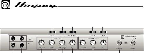
The Front Panel
|
|
|
7 |
8 |
9 |
|
13 |
14 |
|
|
1 |
2 |
3 |
4 |
5 |
6 |
10 |
11 |
12 |
15 |
16 |
1.ONE: (The Channel One Input jacks): The signal output from an instrument or a line-level signal may be connected to this 1/4" input by means of a shielded instrument cable. Either the bright or normal jack may be used. The bright jack enhances the high frequencies of the input signal. The signal at these jacks is sent into the channel one preamp section [tone
and volume controls].
2.TWO: (The Channel Two Input jacks): The signal output from an instrument or a line-level signal may be connected to this 1/4" input by means of a shielded instrument cable. Either the bright or normal jack may be used. The bright jack enhances the high frequencies of the input signal. The signal at these jacks is sent into the channel two preamp section [tone
and volume controls].
3.VOLUME: Use this control to adjust the output level of channel one.
4.TREBLE: Use this to adjust the high frequency level of channel one. This provides up to 12 dB of boost, or 12 dB of cut at 4 kHz. The high frequency output is flat at the center position.
5.MIDRANGE: Use this to adjust the midrange frequency level of channel one. This provides up to 20 dB of boost, or 20 dB of cut at the selected frequency
[8]. The midrange frequency output is flat at the center position.
Rotate the control counter-clockwise for a “contoured” sound (more distant,
less midrange output) or clockwise for a sound which really cuts through.
6.BASS: Use this to adjust the low frequency level of channel one. This provides up to 12 dB of boost, or 12 dB of cut at 40 Hz. The low frequency output is flat at the center position.
7.ULTRA-HI: This switch, when engaged [right side down], enhances the amount of high frequency output of channel one. The amount of boost is dependent on the setting of the volume control [3].
8.1•2•3: This switch selects the frequency that will be affected by the midrange control [5]. The available frequencies are 220 Hz [left side of the switch engaged], 800 Hz [switch in the center position], or 3 kHz (right side of the switch engaged].
9.BASS-CUT/OFF/ULTRA-LO: Engaging the left side of this switch decreases the low frequency output of channel one. Engaging the right side of this switch enhances the low frequency output of channel one. The switch is inactive in the center position.
10.VOLUME: Use this control to adjust the output level of channel two.
5

SVT-VR Bass Guitar Amplifier
The Front Panel continued
|
|
|
7 |
8 |
9 |
|
13 |
14 |
|
|
1 |
2 |
3 |
4 |
5 |
6 |
10 |
11 |
12 |
15 |
16 |
11.TREBLE: Use this to adjust the high frequency level of channel two. This provides up to 12 dB of boost, or 12 dB of cut at 4 kHz. The high frequency output is flat at the center position.
12.BASS: Use this to adjust the low frequency level of channel two. This provides up to 12 dB of boost, or 12 dB of cut at 40 Hz. The low frequency output is flat at the center position.
13.ULTRA-HI: This switch, when engaged [right side down], enhances the amount of high frequency output of channel two. The amount of boost is dependent on the setting of the volume control [10].
14.ULTRA LO: This switch, when engaged [right side down], enhances the low frequency output of channel two.
15.STANDBY SWITCH: Use this switch to turn the standby power on or off. Flick the switch up to turn the standby on.
The standby mode allows the tubes to warm up or remain warm without high voltage being applied to them. This helps extend tube life. This switch should be OFF when first turning the amplifier on. Allow the unit to warm up for at least 20 seconds before switching to the ON position. During short periods of non-use, the amp should be put into standby mode.
16.POWER SWITCH: Use this switch to turn the overall system power on or off. Flick the switch up to turn on the power. The power switch should be engaged prior to the standby switch (as mentioned above, #15). This switch must be turned off to reset the amp after a Fault condition. The adjacent lamp illuminates green when the amplifier is on and is not in standby mode.
6
 Loading...