


 Loading...
MODEL S-4000 CAED
CUT AFTER EDGE
PARTS AND SERVICE MANUAL
MACHINE SERIAL No.:
PART NUMBER 97.2430.0.000
T his manual is valid from the machine serial number J241073
AMF is trademark of AMF Group, Inc.
02/2007
MODEL S-4000 CAED
CUT AFTER EDGE
PARTS AND SERVICE MANUAL
MACHINE SERIAL No.:
PART NUMBER 97.2430.0.000
T his manual is valid from the machine serial number J241073
AMF is trademark of AMF Group, Inc.
02/2007

S-4000 CAED
S-4000 CAED
S-4000 CAED
S-4000 CAED
S-4000 CAED
S-4000 CAED
S-4000 CAED
S-4000 CAED
97.2430.0.000
CUTAFTER EDGE
97.2430.0.000
CUTAFTER EDGE
97.2430.0.000
CUTAFTER EDGE
97.2430.0.000
CUTAFTER EDGE
97.2430.0.000
CUTAFTER EDGE
97.2430.0.000
CUTAFTER EDGE
97.2430.0.000
CUTAFTER EDGE
97.2430.0.000
CUTAFTER EDGE

LIMITEDWARRANTYONNEWAMFREECEEQUIPMENT
Warranty provisions:
A ninety (90) day limited service labor warranty to correct defects in installation, workmanship, or material without charge for labor. This portion of the warranty applies to machines sold as ”installed” only .
A one (1) year limited material warranty on major component parts to replace materials with defects. Any new part believed defective must be returned freight prepaid to AMF Reece, Inc. for inspection. If, upon inspection, the part or material is determined to be defective, AMF Reece, Inc. will replace it without charge to the customer for parts or material.
Service labor warranty period shall begin on the completed installation date. Material warranty shall begin on the date the equipment is shipped from AMF Reece, Inc.
Exclusions:
Excluded from both service labor warranty and material warranty are: (1) Consumable parts which would be normally considered replaceable in day-to-day operations. These include parts such as needles, knives, loopers and spreaders. (2) Normal adjustment and routine maintenance. This is the sole responsibility of the customer. (3) Cleaning and lubrication of equipment. (4) Parts found to be altered, broken or damaged due to neglect or improper installation or application. (5) Damage caused by the use of non-Genuine AMF Reece parts. (6) Shipping or delivery charges.
There is no service labor warranty for machines sold as ”uninstalled”.
Equipment installed without the assistance of a certified technician (either an AMF Reece Employee, a Certified Contractor, or that of an Authorized Distributor) will have the limited material warranty only. Only the defective material will be covered. Any charges associated with the use of an AMF Reece Technician or that of a Distributor to replace the defective part will be the customer’s responsibility.
NO OTHER WARRANTY, EXPRESS OR IMPLIED,AS TO DESCRIPTION, QUALITY, MERCHANTABILITY, and FITNESS FOR APARTICULAR PURPOSE, ORANYOTHER MATTER IS GIVEN BYSELLER OR SELLER’S AGENTIN CONNECTION HEREWITH. UNDER NO CIRCUMSTANCES SHALLSELLER OR SELLER’S AGENT BE LIABLE FOR LOSS OF PROFITS ORANY OTHER DIRECT OR INDIRECTCOSTS, EXPENSES, LOSSES OR DAMAGESARISING OUTOF DEFECTS IN OR FAILURE OF THE EQUIPMENT ORANY PART THEREOF.
WHATTO DO IFTHERE ISAQUESTION REGARDINGWARRANTY
If a machine is purchased through an authorized AMF Reece, Inc. distributor, warranty questions should be first directed to that distributor. However, the satisfaction and goodwill of our customers are of primary concern to AMF Reece, Inc. In the event that a warranty matter is not handled to your satisfaction, please contact the appropriate AMF Reece office:
Europe/Africa/Americas |
Southwest Asia |
||||
Prostejov, Czech Republic |
Istanbul, Turkey |
||||
Phone: |
(+420) |
582-309-275 |
Phone: |
(+90) |
212-465-0707 |
Fax: |
(+420) |
582-360-608 |
Fax: |
(+90) |
212-465-0711 |
e-mail: |
service@amfreece.cz |
e-mail: |
amfreeceturkey@superonline.com |
||
Southeast Asia
Kowloon, Hong Kong Phone: (+852) 2787-2273 Fax: (+852) 2787-5642
e-mail: amfreece@netvigator.com

Warranty Registration Card
(Please Fax or Mail immediately after installation)
Note: All Warranty Claims Void, unless Registration Card on file at AMF Reece HQ
Machine model number:
(S101, S100, S104, S311, Decostitch, S4000 BH, etc)
Manufacturer‘s serial or production number:
Installation Site Information:
Customer‘s Name:
Customer‘s MailingAddress:
Customer‘sTelephone Number:
Supervising Mechanic‘s orTechnician‘s Name:
Signature of Supervising Technician:
AMF Reece Technician‘s Name:
AMF Reece Technician‘s Signature:
Type of garment produced at this location?
Average Daily Production Expected from this machine?
(number of buttonholes, jackets sewn, pants produced, buttons sewn, etc)
Any special requirements required at this location?
What other AMF Reece Machines are at this location?
How can we serve you better?
Tovární 582, 796 25 Prostìjov, Czech Republic
Fax: +420 582 360 606, e-mail: service@amfreece.cz, website: www.amfreece.com
|
|
S4000 CAED |
|
TABLE OF CONTENTS |
|
|
|
|
A - INTRODUCTION |
|
|
1. |
Basic information ............................................................................................ |
1-1 |
2. |
Safety device and labels ................................................................................ |
1-2 |
3. |
General machine parts description ................................................................ |
1-3 |
4. |
Specifications .................................................................................................. |
1-4 |
5. |
Instructions for operator safety and maintenance ....................................... |
1-5 |
6. |
Special accessories .......................................................................................... |
1-6 |
B - MACHINE ASSEMBLY |
|
|
1. |
Content of the shipping box .......................................................................... |
1-8 |
2. Accessories ...................................................................................................... |
1-8 |
|
3. |
Power and air connection .............................................................................. |
1-9 |
4. |
Head pmeumatic ............................................................................................. |
1-10 |
5. |
Installation of thread holder .......................................................................... |
1-11 |
C - PROPER APPLICATION |
|
|
1. |
Power Up/ Home position ............................................................................. |
1-12 |
2. |
Needle installation .......................................................................................... |
1-13 |
3. |
Threading ......................................................................................................... |
1-14 |
D - MACHINE CONTROLS |
|
|
1. |
Progress of sewing .......................................................................................... |
1-15 |
2. |
Operator control panel push buttons and switches .................................... |
1-16 |
3. |
Control panel information .............................................................................. |
1-17 |
4. |
The programming menu ................................................................................. |
1-17 |
5. |
Tests .................................................................................................................. |
1-20 |
6. |
Program version .............................................................................................. |
1-22 |
7. |
Schema of programming ................................................................................ |
1-23 |
8. Parameter checklist ......................................................................................... |
1-24 |
|
E - MACHINE ADJUSTMENTS |
|
|
1. |
Machine home position .................................................................................. |
1-25 |
2. Adjustment of the shifter ............................................................................... |
1-25 |
|
3. |
Principles for machine adjustment ................................................................ |
1-25 |
4. Needle bar ....................................................................................................... |
1-26 |
|
5. |
Bite ................................................................................................................... |
1-27 |
6. |
Feeding ............................................................................................................. |
1-29 |
7. |
Clutch ............................................................................................................... |
1-30 |
8. |
Stitch Density .................................................................................................. |
1-30 |
Released 02/2007
e-mail: service@amfreece.cz; parts@amfreece.cz, website: www.amfreece.com
Phones: +420 582 309 146 (Service), +420 582 309 286 (Spare Parts); Fax: +420 582 360 606

S4000 CAED
TABLE OF CONTENTS
E - MACHINE ADJUSTMENTS |
|
|
9. Looper adjustments ........................................................................................ |
1-31 |
|
10. |
Home position of the clamp plate ............................................................... |
1-34 |
11. |
Clamp plate adjustment ............................................................................... |
1-35 |
12. Trimming mechanism adjustment ................................................................ |
1-35 |
|
13. Adjustment of the clamp plate change-over .............................................. |
1-36 |
|
14. Adjustment of machine head clamping foot .............................................. |
1-37 |
|
15. Thread draw off ............................................................................................ |
1-37 |
|
16. |
Thread tension ............................................................................................... |
1-38 |
17. |
Thread trimming ............................................................................................ |
1-38 |
18. |
Cuts-off blow off .......................................................................................... |
1-39 |
19. |
Thread blow off (special accessory) .......................................................... |
1-40 |
20. Adjustment of stop sensor position ........................................................... |
1-40 |
|
21. |
Replacement of the belt ............................................................................... |
1-41 |
22. |
Protection during voltage fluctuation (special accessory) ....................... |
1-42 |
23. |
Optical fiber .................................................................................................. |
1-43 |
F - MACHINE MAINTENANCE |
|
|
1. Cleaning and maintenance of the machine .................................................. |
1-44 |
|
2. List of regular services ................................................................................... |
1-46 |
|
3. Schema of group lubrication ......................................................................... |
1-47 |
|
4. Machine lubrication ........................................................................................ |
1-48 |
|
5. Disposal measures .......................................................................................... |
1-50 |
|
G - PNEUMATIC DIAGRA |
|
|
Pneumatic diagram .............................................................................................. |
1-51 |
|
H - ELECTRICAL DIRAGRAM |
|
|
Electrical diagram ................................................................................................ |
1-52 |
|
Released 02/2007 e-mail: service@amfreece.cz; parts@amfreece.cz; website: www.amfreece.com Phones: +420 582 309 146 (Service), +420 582 309286 (Spare Parts); Fax: +420 582 360 606

S-4000 CAED
A - INTRODUCTION
1 . BASIC INFORMATION
The sewing machines S-4000 CAED are designed and produced to be very reliable. Important design goals have been achieved to provide a safe machine that is simple and inexpensive to maintain.
The patented rotary needle bar shaft drive, a major benefit, delivers longer needle bar life. The added benefits of lower vibration and less noise, translate into less operator fatigue.
Simple buttonhole length adjustment located outside the machine, eliminates the need for tilt back, while the quick stop repair function delivers safety and makes repairs easier.
A halogen work light is included with the S-4000 CAED and LS, to enhance operator safety and product quality.
Special electronic and mechanical safety devices protect the operator and the machine. There is a special power lock out switch that permits the machine to be locked in the off position, so that it cannot be cycled accidentally. There is an emergency off switch. There is a low air pressure detector that will not permit machine operation if air pressure is dangerously low.
There are safety-warning labels on the machine in all areas that require special care. These must not be removed. If they are lost replace them immediately.
You are the most important safety equipment of all. Be sure you understand the proper operation of the machine. Never remove safety mechanisms or labels. We have made every effort to provide the safest possible machine, but without complete knowledge of how this machine operates, and the use of proper care by the operator, this machine can cause serious injury or death. That is why there are safety warnings throughout these instructions that carry one of these messages.
D A N G E R ! Possible loss of life.
WA R N I N G ! Possible serious injury or machine damage.
N O T I C E ! Possible injury or machine damage.
We recommend that service workers from AMF Reece oversee the installation and initial training of your mechanics and operators.
The most effective safety precaution is a well-managed safety program. Be sure those who use this machine are properly trained. Never disable safety equipment.
Always wear safety goggles when operating or servicing the machine.
Revised 02/2007 |
1-1 |
e-mail: service@amfreece.cz; parts@amfreece.cz; website: www.amfreece.com
Phone: +420 582 309 146 (Service), +420 582 309 286 (Spare Parts); Fax: +420 582 360 606

S-4000 CAED
A - INTRODUCTION
2 . SAFETY DEVICE AND LABELS
|
|
|
|
|
|
|
|
|
|
|
|
|
|
|
|
|
|
|
||
|
|

Warning |
Eye guard |
|
Covers removed, possible injury |
Head cover |
|
Grounding |
Fan cover |
|
Rotational direction |
||
Manometer with pressure sensor |
Standard Label |
Machine head |
|
|
Needle bar cover |
Table Frame |
|
1-2 |
Revised 02/2007 |
e-mail: service@amfreece.cz; parts@amfreece.cz; website: www.amfreece.com |
|
Phones: +420 582 309 146 (Service), |
+420 582 309 286 (Spare Parts); Fax: +420 582 360 606 |
S-4000 CAED
A - INTRODUCTION
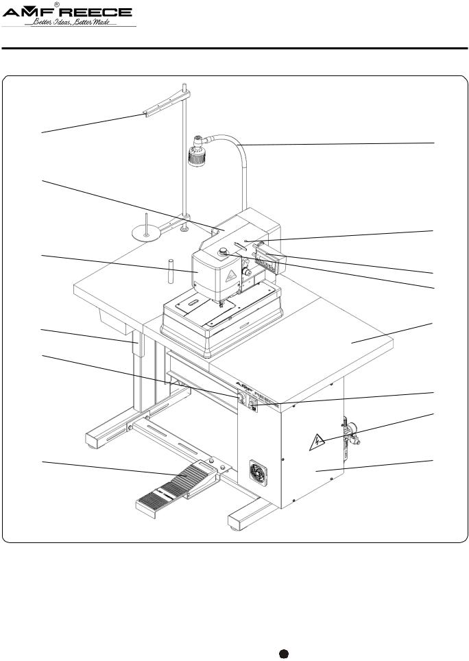
3 . GENERAL MACHINE PARTS DESCRIPTION

Control box Hand wheel
Emergency Stop Button Motor
Table Top Thread Stand Control Panel
Main switch
Foot pedal
Clamps Up/Down button
Air pressure regulator
Air pressure adjustment knob
Halogen Lamp
Rest Pin
27 Warning: when opening the cover, mind your eyes!
Revised 02/2007 |
1-3 |
e-mail: service@amfreece.cz; parts@amfreece.cz; website: www.amfreece.com
Phone: +420 582 309 146 (Service), +420 582 309 286 (Spare Parts); Fax: +420 582 360 606

S-4000 CAED
|
|
|
A - INTRODUCTION |
|
4 . SPECIFICATIONS |
|
|
||
|
|
|
|
|
|
Machine type |
S 4000 CAED |
|
|
|
|
|
|
|
|
Description |
electronical sewing machine for clothing parts |
|
|
|
stitching with cutting after |
|
||
|
|
|
|
|
|
|
|
|
|
|
Sewing speed |
1500-3800 stitches/min |
|
|
|
|
|
|
|
|
Stitch density |
3-14 stitches/cm |
|
|
|
|
|
|
|
|
Machine clamp foot height |
12.7 mm (1/2") |
|
|
|
|
|
|
|
|
Sewing length |
|
7-50 mm |
|
|
|
|
|
|
|
Knife length |
55 mm |
|
|
|
|
|
|
|
|
Maximum work thickness |
to 4 mm (5/32") |
|
|
|
|
|
|
|
|
Bite size |
1,7 - 3,0 mm |
|
|
|
|
|
|
|
|
Recommended thread |
thread size 80, 100, 120 (Tex 40-60) |
|
|
|
|
|
|
|
|
Needle system |
Needle 750 SC 90/14, 70/10 (it is possible to order 80/12) |
|
|
|
|
|
|
|
|
Lubrication |
semi-automatic |
|
|
|
|
|
|
|
|
Operating Conditions |
according to IEC 364-3, IEC 364-5-51 temperature from +5°C to 40°C, |
|
|
|
relative air humidity from 30 to 80 % |
|
||
|
|
|
|
|
|
|
|
|
|
|
Air pressure |
0.55 MPa (80 PSI) |
|
|
|
|
|
|
|
|
Machine db level |
Laeg = 74dB; LWA = 87dB; LpC, peak = 103dB |
|
|
|
|
|
|
|
|
Machine head dimension |
340 mm (height) x 470 (width) x 250 mm (length) |
|
|
|
|
|
|
|
|
Machine head length |
62 kg |
|
|
|
|
|
|
|
|
Table dimension |
700 mm (height) x 600 mm (width) x 1100 mm (length) |
|
|
|
|
|
|
|
|
Table type |
Angle adjustable |
|
|
|
|
|
|
|
|
Electrical Requirements |
1NPE~60Hz 230V/TN-S (according to EN 60204-1) |
|
|
|
1NPE~50Hz 230V/TN-S (according to EN 60204-1) |
|
||
|
|
|
|
|
|
|
|
|
|
|
Line Circuit Breaker |
10A charakteristic C (according to EN 60947-2) |
|
|
|
16A charakteristic B (according to EN 60947-2) |
|
||
|
|
|
|
|
|
|
|
|
|
1-4 |
Revised 02/2007 |
e-mail: service@amfreece.cz; parts@amfreece.cz; website: www.amfreece.com |
|
Phones: +420 582 309 146 (Service), |
+420 582 309 286 (Spare Parts); Fax: +420 582 360 606 |
S-4000 CAED
A - INTRODUCTION
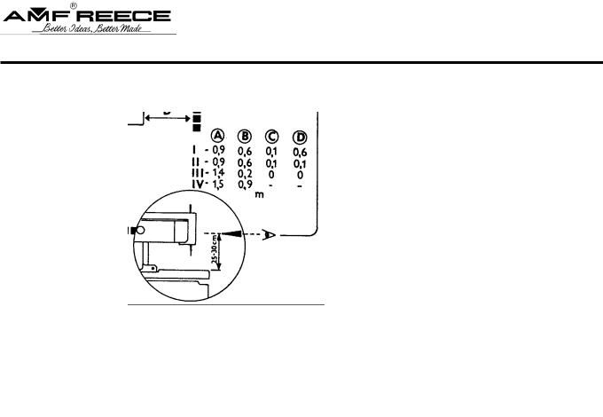
5 . INSTRUCTIONS FOR OPERATOR SAFETY AND MAINTENANCE
When installing the machine we recommend the minimum clearances noted above around the machine. Read all of the instructions that follow. DO NOT PUT THE MACHINE INTO OPERATION UNTIL YOU ARE COMPLETELY FAMILIAR WITH ALL INSTALLATION AND OPERATING INSTRUCTIONS.
DANGER!
-Before connecting the machine to the power supply, be positive that all safety covers are correctly installed.
-Always engage the power lockout switch, or disconnect the main power supply, before removing any safety covers.
WARNING!
-Locate the Emergency Stop button. Be sure you know how to use it.
-Be sure that you have a reliable and uniform power supply.
-Be sure that all electrical supply lines are in good condition and have no signs of damage to avoid electrical shock.
-If any covers become damaged, they must be repaired or replaced immediately.
-Do not touch moving parts of the machine while it is operating.
-Keep clear of the needle.
-Always switch off the main power before changing the needle.
-Before cleaning the machine or performing service to the machine, engage the power lock out switch
or disconnect the main power supply.
-When the machine is not in use engage the power lock out switch or disconnect the main power supply.
-When this machine is used incorrectly, or is incorrectly maintained, it can be dangerous. Everyone who uses this machine, or maintains this machine, must be completely familiar with this manual.
Revised 02/2007 |
1-5 |
e-mail: service@amfreece.cz; parts@amfreece.cz; website: www.amfreece.com
Phone: +420 582 309 146 (Service), +420 582 309 286 (Spare Parts); Fax: +420 582 360 606
S-4000 CAED
A - INTRODUCTION
CAUTION!
-Perform all regular service as described in this manual.
-If there is any problem with the power supply, turn off the main power switch.
-Do not remove, paint over, damage or in any way change safety labels. If a safety label cannot be easily read, replace it.
-Long hair and loose clothing may be dangerous near any machinery. Always contain long hair and avoid loose clothing, so that it cannot be caught by machinery and cause injury.
-Never use this machine while under the influence of drugs or alcohol.
-If anything seems to be operating incorrectly in the machine call for maintenance assistance immediately.
-Be sure that there is adequate light for safe operation. A normal minimum light level is 750 lux.
6 . SPECIA L ACCESSORIES
-machine device, which is not included in the standard equipment of the machine and can be ordered by the customer
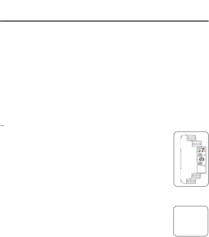
Vo l t a g e g u a r d - r e l a y H R N 3 5
The machine operation is ensured when the power supply is in range AC 230V
± 10 % (EN 60204-1). The manufacturer recommends to equip the machine with the relay HRN-35 in case of larger fluctuation of power supply.
It prevents the machine from damage and in case of large decrease of power supply, the operator is informed by error message.
If the power supply range is exceeded - max 255V and min 165V the voltage guard - relay HRN-35 which ensures that machine does not start. After the power supply is in required range, it is possible to start the machine.
N e e d l e s 7 5 0 S C 8 0 / 1 2 , 90/14
- the manufacturer recommends to use these needles when sewing thin material
-part numbers 02.0750.2.100 (80/12), 02.0750.2.110 (90/14)
1-6 |
Revised 02/2007 |
e-mail: service@amfreece.cz; parts@amfreece.cz; website: www.amfreece.com |
|
Phones: +420 582 309 146 (Service), |
+420 582 309 286 (Spare Parts); Fax: +420 582 360 606 |
S-4000 CAED
A - INTRODUCTION
C o n n e c t o r Ø 8
-order it if the connecting tube has the inner diameter 8 mm. The connector Ø 10 is supplied with the machine.
-part number is 12.0008.3.607
Reduction
-place an order in case you use connections with inch threads (order number 12.0008.3.081)
|
|
|
|
|
|
|
|
|
|
|
|
Hand valve
-to dissipate any air from the machine, order it (air circuit is bled). It is necessary to order the
connectors (see below) to the hand valve for connection to the air tubes.
-part number 12.0008.3.463
Connectors |
|
|
|
|
|
|
12.0008.3.464 |
Ø 8 |
for connection to the tube with inner Ø |
8 mm |
|
|
12.0008.3.466 |
Ø |
10 |
for connection to the tube with inner Ø |
10 mm |
|
12.0008.3.467 |
Ø |
12 |
for connection to the tube with inner Ø |
12 mm* |
|
12.0008.3.465 |
Ø |
16 |
for connection to the tube with inner Ø |
16 mm* |
*To connect the tube with inner Ø 12 and Ø 16, it is also necessary to order Ø 10.
Thread Draw - Off Kit 03.5524.0.004
- order this device if you would like to use
the machine for both, sewing and trimming.
without |
|
trimming |
with trimming |
Thread Blow - Off Kit 03.5524.0.023
-the device enables thread tail at
the needle to be caught above the clamping feet
Revised 02/2007 |
1-7 |
e-mail: service@amfreece.cz; parts@amfreece.cz; website: www.amfreece.com
Phone: +420 582 309 146 (Service), +420 582 309 286 (Spare Parts); Fax: +420 582 360 606
S-4000 CAED
|
B - MACHINE ASSEMBLY |
|
1 . CONTENT OF THE SHIPPING BOX |
|
|
1. |
The shipment contains one box. |
|
|
||
2. |
There is a carton with accessories, service manual with |
|
|
parts section and thread stand in the box. |
|
3. |
During unpacking the shipment, follow the labels which are on a |
|
|
cover. |
|
C AU T I O N : If the machine or crate was damaged in shipment inform the freight company immediately. Check the contents of the crate immediately and report any damage or missing items to the manufacturer immediately, late reports will not be considered!
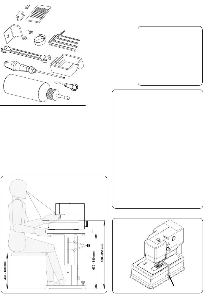
2 . ACCESSORIES |
STANDARD ACCESSORIES |
|
A package of accessories is supplied with the machine, please refer to page 3-48 for detailed descriptions.
The height of the working area is normaly set in range 830 - 850 mm from the manufacturer. When using this height of the working area, recommended height of the operator seat is in range 430 - 460 mm. The height of the table can be set in range 670 - 880 mm by screws .
* It is possible to tilt the operator’s head up to 5°.
Remove the shipping strap after unpacking the machine, the use of this strap is recommended anytime the machine is transported (This is valid for all types of tables - parallel, crosswise).
|
|
1-8 |
Revised 02/2007 |
e-mail: service@amfreece.cz; parts@amfreece.cz; website: www.amfreece.com |
|
Phones: +420 582 309 146 (Service), |
+420 582 309 286 (Spare Parts); Fax: +420 582 360 606 |
S-4000 CAED
B - MACHINE ASSEMBLY
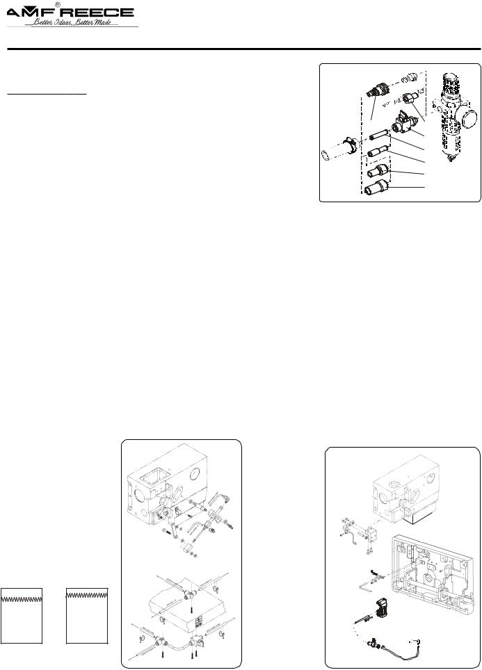
3 . POWER AND AIR CONNECTION
1. The machine is equipped with a quick coupler required with connector for inner of the tube 10. The connector for inner of the tube 8 is not
supplied with the machine, a customer has to order it. The manufacturer recommends to use connector for customers who requires to connect the tube with connector NPT.
If a customer needs to use a shut off valve , which allows fast releasing of the air from the circuit, he must order it.
A variety of connectors can be used separately or in combination to adapt to the available input supply hose. It depends on type of the tube which is used by a customer. These connectors are not included in the accessories. A tubing clamp is provided.
N OT E : Parts , , , are included in Extra Parts - see 3-48.
2. After air connection check the set air pressure on the dial of the regulator. It should be in range 0.5 - 0.6 MPa. The green pointer indicates the lowest working air pressure 0.5 MPa, which is set
from the manufacturer on the regulator . If the air pressure is lower than 0.5 MPa after connecting the machine to the power supply, the red LED lights up on the regulator and „Low Pressure“ message appears on the control panel display. To adjust the working pressure, loosen the regulator cap lock and turn the regulator cap clockwise to increase the pressure. Push the regulator cap
down. The LED  is for setting the minimal operation air pressure.
3. Power supply must be 230 volts. Receptacle plug must meet requirements of IEC standard 364-4-41, its circuit breaker must be minimal 10A with characteristic C according to the EN 60947-2 (or 16A with characteristic B). No other devices must not be connected to the circuit breaker of the socker. The hand wheel  must turn counter clockwise.
The machine is equipped with a filters which contain capacitors which generate an high frequency leakage current. In order to prevent nuisance tripping, residual current protection device must be protected against these high frequency currents: this is the case for industrial residual current device (example „S“ type).
Revised 02/2007 |
1-9 |
e-mail: service@amfreece.cz; parts@amfreece.cz; website: www.amfreece.com
Phone: +420 582 309 146 (Service), +420 582 309 286 (Spare Parts); Fax: +420 582 360 606

S-4000 CAED
B - MACHINE ASSEMBLY
4 . HEAD PNEUMATIC
J0I1
BQ2
|
J0I2 |
J1B |
* |
|
|

J5A
J6A
J6B
— cutting drawn-off thread
— clamping feet
— thread trimming
— shifting clamping plate
MARKING |
J X X X |
|
OF HOSES |
||
|
1-10
|
— changing the direction of sewing |
|
— blowing off the cut material |
|
— loopers, thread blow off (*Extra parts) |
|
J0I1; J0I2 — air supply |
air supply |
BQ2 - manometer with pressure sensor |
|
1, 2 — X => marking of pneumatic cylinder 1, 2 — X => auxiliary line
A = supply; B = return line; I = valve supply
Revised 02/2007
e-mail: service@amfreece.cz; parts@amfreece.cz; website: www.amfreece.com Phones: +420 582 309 146 (Service), +420 582 309 286 (Spare Parts); Fax: +420 582 360 606
S-4000 CAED
B - MACHINE ASSEMBLY
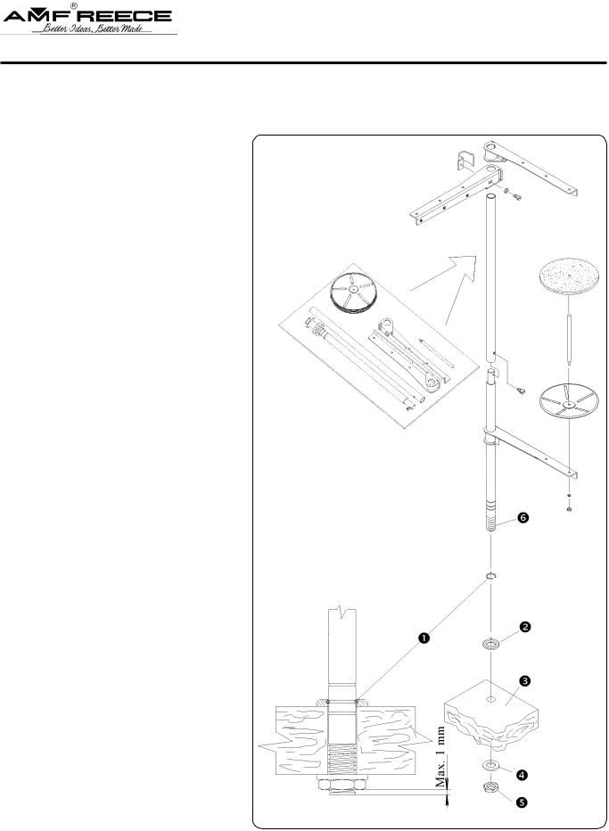
5 . I N S TA L L AT I O N O F T H R E A D H O L D E R
1 . Put the thread holder together as per the drawing.
2 . Position of the ring enables assembly of the complete holder onto tables with different thickness of the tabletop. The end of the rod with threads shall not overtop the nut more than 1 mm.
3 . Once the ring is positioned, insert the mat with the groove towards the ring; place the rod into the opening in the tabletop (on the right at the back). Tighten the nut with the mat
underneath.
Revised 02/2007 |
1-11 |
e-mail: service@amfreece.cz; parts@amfreece.cz; website: www.amfreece.com
Phone: +420 582 309 146 (Service), +420 582 309 286 (Spare Parts); Fax: +420 582 360 606
Loading...