


 Loading...
MODEL S-311
ELECTRONIC EYELET BUTTONHOLE MACHINE
PARTS AND SERVICE MANUAL
MACHINE SERIAL No.
PART NUMBER 97. 1930.0.001
This manual is valid from the machine serial No.: J190410
AMF is trademark of AMF Group, Inc.
09/ 2 0 0 6

MODEL S-311
ELECTRONIC EYELET BUTTONHOLE MACHINE
PARTS AND SERVICE MANUAL
MACHINE SERIAL No.
PART NUMBER 97. 1930.0.001
This manual is valid from the machine serial No.: J190410
AMF is trademark of AMF Group, Inc.
09/ 2 0 0 6

S-311
S-311
S-311
S-311
S-311
97.1930.0.001 ELECTRONIC EYELET BUTTONHOLE MACHINE
PARTS AND SERVICE MANUAL
97.1930.0.001 ELECTRONIC EYELET BUTTONHOLE MACHINE
PARTS AND SERVICE MANUAL
97.1930.0.001 ELECTRONIC EYELET BUTTONHOLE MACHINE
PARTS AND SERVICE MANUAL
97.1930.0.001 ELECTRONIC EYELET BUTTONHOLE MACHINE
PARTS AND SERVICE MANUAL
97.1930.0.001 ELECTRONIC EYELET BUTTONHOLE MACHINE
PARTS AND SERVICE MANUAL
S-311 |
97.1930.0.001 ELECTRONIC EYELET BUTTONHOLE MACHINE |
PARTS AND SERVICE MANUAL |

LIMITED WARRANTY ON NEW AMF REECE EQUIPMENT
Warranty provisions:
A ninety (90) day limited service labor warranty to correct defects in installation, workmanship, or material without charge for labor. This portion of the warranty applies to machines sold as ”installed” only .
A one (1) year limited material warranty on major component parts to replace materials with defects. Any new part believed defective must be returned freight prepaid to AMF Reece, Inc. for inspection. If, upon inspection, the part or material is determined to be defective, AMF Reece, Inc. will replace it without charge to the customer for parts or material.
Service labor warranty period shall begin on the completed installation date. Material warranty shall begin on the date the equipment is shipped from AMF Reece, Inc.
Exclusions:
Excluded from both service labor warranty and material warranty are: (1) Consumable parts which would be normally considered replaceable in day-to-day operations. These include parts such as needles, knives, loopers and spreaders. (2) Normal adjustment and routine maintenance. This is the sole responsibility of the customer. (3) Cleaning and lubrication of equipment. (4) Parts found to be altered, broken or damaged due to neglect or improper installation or application. (5) Damage caused by the use of non-Genuine AMF Reece parts. (6) Shipping or delivery charges.
There is no service labor warranty for machines sold as ”uninstalled”.
Equipment installed without the assistance of a certified technician (either an AMF Reece Employee, a Certified Contractor, or that of an Authorized Distributor) will have the limited material warranty only. Only the defective material will be covered. Any charges associated with the use of an AMF Reece Technician or that of a Distributor to replace the defective part will be the customer’s responsibility.
NO OTHER WARRANTY, EXPRESS OR IMPLIED,AS TO DESCRIPTION, QUALITY, MERCHANTABILITY, and FITNESS FOR APARTICULAR PURPOSE, ORANYOTHER MATTER IS GIVEN BYSELLER OR SELLER’S AGENT IN CONNECTION HEREWITH. UNDER NO CIRCUMSTANCES SHALL SELLER OR SELLER’S AGENT BE LIABLE FOR LOSS OF PROFITS ORANY OTHER DIRECT OR INDIRECT COSTS, EXPENSES, LOSSES OR DAMAGESARISING OUT OF DEFECTS IN OR FAILURE OF THE EQUIPMENT ORANY PART THEREOF.
WHATTO DO IFTHERE ISAQUESTION REGARDINGWARRANTY
If a machine is purchased through an authorized AMF Reece, Inc. distributor, warranty questions should be first directed to that distributor. However, the satisfaction and goodwill of our customers are of primary concern to AMF Reece, Inc. In the event that a warranty matter is not handled to your satisfaction, please contact the appropriate AMF Reece office:
Europe/Africa/Americas |
Southwest Asia |
||||
Prostejov, Czech Republic |
Istanbul, Turkey |
||||
Phone: |
(+420) |
582-309-275 |
Phone: |
(+90) |
212-465-0707 |
Fax: |
(+420) |
582-360-608 |
Fax: |
(+90) |
212-465-0711 |
e-mail: |
service@amfreece.cz |
e-mail: |
amfreeceturkey@superonline.com |
||
Southeast Asia
Kowloon, Hong Kong Phone: (+852) 2787-2273 Fax: (+852) 2787-5642
e-mail: amfreece@netvigator.com

Warranty Registration Card
(Please Fax or Mail immediately after installation)
Note: All Warranty Claims Void, unless Registration Card on file at AMF Reece HQ
Machine model number:
(S101, S100, S104, S311, Decostitch, S4000 BH, etc)
Manufacturer‘s serial or production number:
Installation Site Information:
Customer‘s Name:
Customer‘s MailingAddress:
Customer‘sTelephone Number:
Supervising Mechanic‘s orTechnician‘s Name:
Signature of Supervising Technician:
AMF Reece Technician‘s Name:
AMF Reece Technician‘s Signature:
Type of garment produced at this location?
Average Daily Production Expected from this machine?
(number of buttonholes, jackets sewn, pants produced, buttons sewn, etc)
Any special requirements required at this location?
What other AMF Reece Machines are at this location?
How can we serve you better?
Tovární 582, 796 25 Prostějov, Czech Republic
Fax: +420 582 360 606, e-mail: service@amfreece.cz, website: www.amfreece.com
|
|
S-311 |
|
TABLE OF CONTENTS |
|
|
|
|
A - INTRODUCTION |
|
|
1. |
Basic information ............................................................................................................................ |
1-1 |
2. |
Safety labels and device ................................................................................................................. |
1-2 |
3. |
General machine parts descriptions ................................................................................................. |
1-3 |
4. |
Specification ................................................................................................................................... |
1-4 |
5. |
Buttonhole description .................................................................................................................... |
1-6 |
6. |
Instructions for operator safety and maintenance of the machine S-311 ......................................... |
1-7 |
7. |
Special device ................................................................................................................................. |
1-9 |
7.1.Light ........................................................................................................................................ |
1-9 |
|
7.2.Adjustable cutting length steel (ACL) ............................................................................................ |
1-9 |
|
7.3.Manual machine control ................................................................................................................ |
1-9 |
|
B - MACHINE ASSEMBLY |
|
|
1. |
Content of the shipping box ........................................................................................................... |
1-10 |
2. |
Table adjustment ............................................................................................................................ |
1-10 |
3. |
Connection of the machine head with the control box ................................................................... |
1-12 |
4. |
Belt tension .................................................................................................................................... |
1-13 |
5. |
Power and air connection ............................................................................................................... |
1-14 |
6. |
Thread stand installation ................................................................................................................. |
1-15 |
7. |
Lubrication ..................................................................................................................................... |
1-16 |
C - PROPER APPLICATION |
|
|
1. Power up / home position ................................................................................................................ |
1-17 |
|
2. Needle installation ............................................................................................................................ |
1-18 |
|
3. Threading ........................................................................................................................................ |
1-19 |
|
D - MACHINE CONTROLS |
|
|
1. |
Operation ....................................................................................................................................... |
1-22 |
2. |
Needle instalation ........................................................................................................................... |
1-18 |
3. |
The buttonhole setting .................................................................................................................... |
1-25 |
3.1. Setting the parameters of the eye .................................................................................................. |
1-25 |
|
3.2. Setting the first and the second row of stitches .............................................................................. |
1-26 |
|
3.3. Setting a bar .................................................................................................................................. |
1-27 |
|
4. |
The sewing speed setting ................................................................................................................ |
1-28 |
5. |
Parameters saving ........................................................................................................................... |
1-28 |
6. |
Copying adjusted perameters under new number ........................................................................... |
1-29 |
7. |
Trimm thread end lengths adjustment ............................................................................................. |
1-29 |
8. |
Setting the cutting ........................................................................................................................... |
1-30 |
9. |
Service mode .................................................................................................................................. |
1-31 |
10. Cycle mode .................................................................................................................................... |
1-32 |
|
11. Manual cut mode ........................................................................................................................... |
1-33 |
|
Revised 03/2006 |
|
|
E-mail: service@amfreece.cz; parts@amfreece.cz; website: www.amfreece.com |
1-i |
|
Phones: +420 582 309 146 (Service), +420 582 309 286 (Spare Parts); Fax: +420 582 360 606 |
||

S-311
TABLE OF CONTENTS
E - STANDARD MACHINE ADJUSTMENT |
|
|
1. |
Standard buttonhole shapes set by the manufacturer ...................................................................... |
1-34 |
2. |
The sewing drive sensor plates adjustment ..................................................................................... |
1-35 |
3. |
The bedplate home position adjustment .......................................................................................... |
1-36 |
4. |
The race mechanism adjustment ..................................................................................................... |
1-37 |
5. |
The sewing mechanism height control ............................................................................................ |
1-38 |
6. |
Mechanism adjustment for material clamping ................................................................................. |
1-39 |
7. |
Spreading of a material ................................................................................................................... |
1-40 |
8. |
Adjustment of the cutting mechanism ............................................................................................. |
1-41 |
9. |
Setting the needle bar height ........................................................................................................... |
1-43 |
10. Spreader and looper cam adjustment ............................................................................................. |
3-44 |
|
11. Loopers adjustment ........................................................................................................................ |
1-44 |
|
12. Spreaders adjustment ..................................................................................................................... |
1-45 |
|
13. Adjustment of the bite mechanism .................................................................................................. |
1-46 |
|
14. Upper thread trimming mechanism - AF/LTT .............................................................................. |
1-47 |
|
15. Adjustment of the upper thread pick-up height ............................................................................... |
1-48 |
|
16. Upper trimming and lower interception - CT .................................................................................. |
1-49 |
|
17. The gimb draw-off adjustment -CT ................................................................................................ |
1-51 |
|
18. The trimming mechanism a djustment - LTT .................................................................................. |
1-52 |
|
19. Adjustment of the adjustable cutting steel holder ........................................................................... |
1-55 |
|
20. Setting the thread tension and thread draw off ................................................................................ |
1-56 |
|
F - MACHINE MAINTENANCE |
|
|
1. |
Cleaning and maintenance of the machine ...................................................................................... |
1-57 |
2. |
Periodic maitenance ........................................................................................................................ |
1-59 |
3. |
Scheme of the lubrication distribution ............................................................................................. |
1-60 |
4. |
Machine lubrication ........................................................................................................................ |
1-61 |
5. |
Machine disposal ............................................................................................................................ |
1-63 |
G - DOCUMENTATION |
|
|
Flow diagram ....................................................................................................................................... |
1-64 |
|
MODEL S-311+I OPERATING INSTRUCTIONS
|
Revised 03/2006 |
|
E-mail: service@amfreece.cz; parts@amfreece.cz; website: www.amfreece.com |
1-ii |
Phones: +420 582 309 146 (Service), +420 582 309 286 (Spare Parts); Fax: +420 582 360 606 |

S-311
A - INTRODUCTION
1 . B A S I C I N F O R M AT I O N
Sewing machine S-311 is determined to sew buttonholes for outwears. Buttonholes type are listed on page no. 1-6. The sewing machine S-311 is designed and produced to be simple for operation and very reliable. Important design goals have been made to provide a safe machine that is simple and inexpensive to maintain.
Sewing machine S-311 has four basic models: AF, CT, LTT and RDE. Each model can be combined with ACL, except the model RDE.
Special electronic and mechanical safety devices protect the operator and the machine. There is a special power lock out switch that permits the machine to be locked in the off position, so that it cannot be cycled accidentally. There is a low air pressure detector that will not permit machine operation if air pressure is dangerously low.
There are safety-warning labels on the machine in all areas that require special care. These must not be removed. If they are lost replace them immediately.
You are the most important safety equipment of all. Be sure you understand the proper operation of the machine. Never remove safety mechanisms or labels. We have made every effort to provide the safest possible machine, but without complete knowledge of how this machine operates, and the use of proper care by the operator, this machine can cause serious injury or death. That is why there are safety warnings throughout these instructions that carry one of these messages.
Machine types are listed in the table on the manual page no. 1-4, 1-5.
DANGER! Possible loss of life.
WARNING! Possible serious injury or machine damage.
NOTICE! Possible injury or machine damage.
We recommend that service workers from AMF Reece oversee the installation and initial training of your mechanics and operators.
The most effective safety precaution is a well-managed safety program. Be sure those who use this machine are properly trained. Never disable safety equipment.
Always wear safety goggles when operating or servicing the machine.
EXPLANATION OF ABBREVIATIONS IN THE MANUAL TEXT
|
CA |
Cut After |
|
|
CB |
Cut Before |
|
|
AF |
Adjustable Flybar |
|
|
|
|
|
|
CT |
Cord Trimming of all threads - short tail of lower thread |
|
|
|
|
|
|
LTT |
Cord Trimming of all threads - long tail of lower thread |
|
|
|
|
|
|
ACL |
Adjustable Cutting Length (Cut) |
|
|
|
|
|
Revised 03/2006 |
1-1 |
||
e-mail: service@amfreece.cz; parts@amfreece.cz; website: www.amfreece.com
Phones: +420 582 309 146 (Service); +420 582 309 286 (Spare Parts); Fax: +420 582 360 606

S-311
A - INTRODUCTION
2 . S A F E T Y L A B E L S A N D D E V I C E
|
12 10 |
|
|


11 

28 


15 |
13
21
|
Warning |
|
Needle bar cover |
|
Danger possible injury |
|
Eye guard |
|
Covers removed possible injury |
|
Drive belt cover |
|
Switch |
|
Air pressure adjustment knob |
|
Grounding |
|
Rear cover |
|
Rotational direction |
|
Motor pulley cover |
|
Standard label |
|
Foot pedal |
|
Air pressure switch |
||
|
|
|
|
1-2 |
|
|
Revised 03/2006 |
|
|
e-mail: service@amfreece.cz; parts@amfreece.cz; website: www.amfreece.com |
|
Phones: +420 582 309 146 (Service); +420 582 309 286 (Spare Parts); Fax: +420 582 360 606

S-311
A - INTRODUCTION
3 . G E N E R A L M A C H I N E PA R T S D E S C R I P T I O N S
20 19 16 |
23 |
22
18
17
14 


24 |
27 |
Display |
Main power switch |
Table |
Cutting activation button |
Control box |
Air pressure regulator |
Hand wheel |
|
Emergency Stop button |
|
Motor |
|
Table top |
|
Thread stand |
|
Revised 03/2006 |
1-3 |
e-mail: service@amfreece.cz; parts@amfreece.cz; website: www.amfreece.com |
|
Phones: +420 582 309 146 (Service); +420 582 309 286 (Spare Parts); Fax: +420 582 360 606

S-311
A - INTRODUCTION
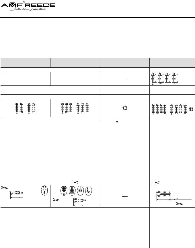
4. S P E C I F I C AT I O N
S-311 Elektronic buttonhole machine with chain stitch is possible to use for men`s and women`s wear. Possible to use gimp thread, not in round eye.
Machine type/model |
AF |
CT 16 - 20 mm |
CT 20 - 24 mm |
CT 24 - 28 mm |
CT 28 - 32 mm |
Sewing speed |
|
1000 to 2000 stitches/min (500 to 1000 rev/min of the drive shaft) |
|
||
The length |
10 to 50 mm |
16 to 20 mm |
20 to 24 mm |
24 to 28 mm |
28 to 32 mm |
of hole |
|||||
Stitch Density |
|
0,5 to 2,0 mm (increments of 0,1 mm) |
|
||
Number of stitches in the eye |
|
|
4 to 20 |
|
|
Bite Range Elecctronic |
|
2,1 mm (± 0,3 mm electronic); 2,7 mm (± 0,3 mm electronic) |
|
||
Buttonhole style |
|
|
|
|
|
|
max 3,5 mm |
|
|
|
|
Eye type |
No eye; 2,2 x 3,0 mm; 2,8 x 4,2 mm; 3,0 x 4,6 mm; 3,2 x 5,0 mm; 3,4 x 4,2 mm |
||||
|
|||||
Flybar length |
3,0 - 20,0 mm |
|
See section D 3.3 |
|
|
Length of the cross bar |
4 to 8 mm |
|
4 to 6 mm |
|
|
Cross bar density |
0,5 to 1,5 mm |
|
0,5 to 1,5 mm |
|
|
Number of stitches in the round end |
4 to 20 |
|
|
|
|
Clamp foot height (max) |
|
|
12 mm |
|
|
Maximum work thickness |
|
|
in 8,0 mm |
|
|
Buttonhole Cutting Mode |
|
Cut before (CB), cut after (CA), no cut (OFF) |
|
||
Cutting Space |
|
|
- 0,50 to + 1,2 mm |
|
|
Cut position (Y axis) |
|
|
± 1,5 mm |
|
|
Bedplate movement |
|
|
64 mm |
|
|
Needle system |
02.0558.0.111 (Nm 100) |
|
02.0558.1.112 (Nm 110) |
|
|
Recommended threads* |
|
|
80, 100, 120, gimp size 30. |
|
|
Upper thread trimming
Lower thread and gimp trimming |
|
(Short ends) |
|
||
|
|
|
|
||
L |
= 3 to 7 mm |
L = 16 to 20 mm |
L = 20 to 24 mm |
L = 24 to 28 mm |
L = 28 to 32 mm |
|
|
||||
Cutting space |
|
L+L1 = 23 to 27 mm |
L+L1 = 27 to 31 mm |
L+L1 = 31 to 35 mm |
L+L1 = 35 to 39 mm |
Operating Condition |
according to IEC 364-3, IEC 364-5-51 temperature from +5°C to 40°C, relative air humidity from 30 to 8 0% |
||||
Air pressure |
0,55 MPa = 80 PSI |
Machine db Level |
LwA=86,9db; LpfA=74,8 db; Noise measurement according to EN ISO 3746:1995 |
Machine Head Dimension |
530 mm (height) x 370 mm (width) x 560 mm (depth) |
Machine Head Weight |
64 kg |
Table Dimensions |
730 mm (height) x 1100 mm (width) x 700 mm depth) + 150 mm distance |
Machine Weight |
175 kg |
Electrical requirements |
1NPE~60Hz 230 V/TN/S; 1NPE~50Hz 230 V/TN/S |
Line Circuit Breaker |
Min. 10A Characteristic C (EN60947-2) |
* N o t e : |
If a customer uses thread size 100 and less, the manufacturer recommends to use the left looper 17.0069.4.019 |
|
If you use poor quality threads on the machine, the thread can burn at the needle (producer recommend |
|
decrease machine´s speed). |
1-4 |
Revised 03/2006 |
|
e-mail: service@amfreece.cz; parts@amfreece.cz; website: www.amfreece.com |
|
Phones: +420 582 309 146 (Service); +420 582 309 286 (Spare Parts); Fax: +420 582 360 606 |
S-311
A - INTRODUCTION
CT 16 - 32 mm |
LTT |
RDE |
Machine type/model |
1000 to 2000 stitches/min (500 to 1000 rev/min of the drive shaft) |
Sewing speed |
||
16 to 32 mm |
10 to 36 mm |
|
The length |
|
of hole |
||
0,5 to 2,0 mm (increments of 0,1 mm) |
|
Stitch Density |
|
4 to 20 |
|
8 to 60 |
Number of stitches in the eye |
2,1 mm (± 0,3 mm electronic); 2,7 mm (± 0,3 mm electronic) |
|
Bite Range Elecctronic |
|
|
|
|
Buttonhole style |
|
|
No eye; 2,2 x 3,0 mm; 2,8 x 4,2 mm; |
|
2 to 7 mm |
Eye type |
||||||||||||||||||||
|
|
3,0 x 4,6 mm; 3,2 x 5,0 mm; 3,4 x 4,2 mm |
|
|
|||||||||||||||||||||
|
|
|
|
|
|
|
|||||||||||||||||||
|
|
|
|
|
|
|
|
|
|
|
|
|
|
|
|
|
|
|
|
|
|
|
|
|
|
|
|
See section D 3.3 |
|
|
|
|
|
|
|
|
|
|
|
|
|
|
|
|
|
|
Flybar length |
||||
|
|
|
|
|
|
|
|
|
|
|
|
|
|
|
|
|
|
||||||||
|
|
4-6 mm |
|
|
|
|
4-8 mm |
|
|
|
|
Length of the cross bar |
|||||||||||||
|
|
|
|
|
|
|
|
|
0,5 - 1,5 mm |
|
|
|
Cross bar density |
||||||||||||
|
|
|
|
|
|
|
|
|
|
|
|
|
|
|
|
|
|
|
|
|
|
|
|
|
Number of stitches in the round end |
|
|
|
|
|
|
|
|
|
|
|
|
|
|
|
|
|
|
|
|
|
|
|
|
|
|
|
|
|
|
12 mm |
|
|
|
|
|
|
|
|
|
|
|
|
|
|
|
5 mm |
Clamp foot height (max) |
||||
|
|
in 8,0 mm |
|
|
|
|
|
|
|
|
|
|
|
|
|
|
|
1,5 to 2,5 mm |
Maximum work thickness |
||||||
|
|
Cut before (CB), cut after (CA), no cut (OFF) |
|
|
|
Buttonhole Cutting Mode |
|||||||||||||||||||
|
|
- 0,50 to + 1,2 mm |
|
|
|
|
|
|
|
|
|
|
|
|
|
|
|
|
|
|
Cutting Space |
||||
|
|
|
|
|
|
|
|
|
|
|
|
|
|
|
|
|
|
||||||||
|
|
|
± 1,5 mm |
|
|
|
|
|
|
|
|
|
|
|
|
|
|
|
|
|
|
Cut position (Y axis) |
|||
|
|
|
|
|
|
|
|
|
|
|
|
|
|
|
|
|
|
|
|
|
|
|
|
|
|
|
|
|
|
64 mm |
|
|
|
|
|
|
|
|
|
|
|
|
|
|
|
62,5 mm |
Bedplate movement |
||||
0.0558.1.112 (Nm 110) |
|
|
|
|
|
|
|
|
|
|
|
|
|
0.0558.0.111 (Nm 100) |
Needle system |
||||||||||
|
|
|
|
|
80, 100, 120, gimp size 30. |
|
|
|
Recommended threads* |
||||||||||||||||
|
|
|
|
|
|
|
|
|
|
|
|
|
|
|
|
|
|
|
|
|
|
|
|
|
Upper thread trimming |
|
|
|
|
|
|
|
|
|
|
|
|
|
|
|
|
|
|
|
|
|
|
|
|
|
|
(short ends) |
|
|
|
|
|
|
|
|
|
|
|
|
|
|
|
|
|
|
Lower thread and gimp trimming |
||||||
|
|
|
|
|
|
|
|
|
|
|
|
|
|
|
|
|
|
||||||||
|
|
|
|
|
|
|
|
|
|
|
|
|
|
|
|
|
|
||||||||
|
|
|
|
|
|
|
|
|
|
|
|
|
|
|
|
|
|
|
|
|
|
|
|
|
|
L +3 to 7 mm |
|
|
|
|
L = 23 to 27 mm |
|
|
L |
3 to 7 mm |
27 to 31 mm |
|
|
||
|
|
|
|
|
31 to 35 mm |
(long ends) |
L 16 to 36 mm |
Cutting space |
|
35 to 39 mm |
|
according to IEC 364-3, IEC 364-5-51 temperature from +5°C to 40°C, relative air humidity from 30 to 8 0% |
Operating Condition |
0,55 MPa = 80 PSI |
Air pressure |
|
|
LwA=86,9db; LpfA=74,8 db; Noise measurement according to EN ISO 3746:1995 |
Machine db Level |
530 mm (height) x 370 mm (width) x 560 mm (depth) |
Machine Head Dimension |
64 kg |
Machine Head Weight |
730 mm (height) x 1100 mm (width) x 700 mm depth) + 150 mm distance |
Table Dimensions |
175 kg |
Machine Weight |
1NPE~60Hz 230 V/TN/S; 1NPE~50Hz 230 V/TN/S |
Electrical requirements |
Min. 10A Characteristic C (EN60947-2) |
Line Circuit Breaker |
Revised 03/2006 |
1-5 |
e-mail: service@amfreece.cz; parts@amfreece.cz; website: www.amfreece.com
Phones: +420 582 309 146 (Service); +420 582 309 286 (Spare Parts); Fax: +420 582 360 606

S-311
A - INTRODUCTION
5. B U T T O N H O L E D E S C R I P T I O N
3 |
14 |
15
5
2 |
1 |
8 |
9
6 |
7 |
4 

7
10 |
11 |
12 |
13 |
|
The first row of stitches |
The length of buttonhole |
|
The second row of stitches |
Fly bar AF |
|
Eye |
Cross bar CRB |
|
Cutting space |
Open End |
|
Stitch density |
Round End RDE |
|
Bite size |
Buttonhole width |
|
The length of a bar |
Buttonhole lenght |
|
The length of cutting |
|
1-6 Revised 03/2006 e-mail: service@amfreece.cz; parts@amfreece.cz; website: www.amfreece.com
Phones: +420 582 309 146 (Service); +420 582 309 286 (Spare Parts); Fax: +420 582 360 606
S-311
A - INTRODUCTION
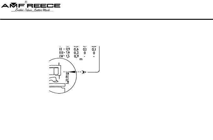
6 . I N S T R U C T I O N S F O R O P E R AT O R S A F E T Y A N D M A I N T E N A N C E O F T H E M A C H I N E S - 311
When installing the machine the manufacturer recommends the minimum clearance mentioned above around the machine. Read all of the instructions that follow. DO NOT PUT THE MACHINE INTO OPERATION UNTIL YOU ARE COMPLETELY FAMILIAR WITH ALL INSTALLATION AND OPERATING INSTRUCTIONS.
D A N G E R !
-Before connecting the machine to the power supply, be positive that all safety covers are correctly installed.
-Always engage the power lockout switch, and disconnect the main power supply, before removing any safety covers.
-Never connect the machine to the power supply when any cover is removed.
-It is forbidden to disconnect all connectors when the machine is switched on and connected to
the power supply. T h e e l e c t r i c a l c o m p o n e n t s a n d m o t o r s c a n b e d a m a g e d .
WA R N I N G !
-Locate the Emergency Stop button. Be sure you know how to use it.
-Be sure that you have a reliable and uniform power supply.
-Be sure that all electrical cables are in good condition and have no signs of damage to avoid electrical shock.
-If any covers become damaged, they must be repaired or replaced immediately.
-Do not touch moving parts of the machine while it is operating.
-Keep clear of the needle.
-Always switch off the main power before changing the needle.
-Before cleaning the machine or performing service to the machine, engage the power lock out switch or disconnect the main power supply.
-When the machine is not in use engage the power lock out switch or disconnect the main power supply.
Revised 03/2006 |
1-7 |
e-mail: service@amfreece.cz; parts@amfreece.cz; website: www.amfreece.com
Phones: +420 582 309 146 (Service); +420 582 309 286 (Spare Parts); Fax: +420 582 360 606

S-311
A - INTRODUCTION
-When this machine is used incorrectly, or is incorrectly maintained, it can be dangerous.
-Everyone who uses this machine, or maintains this machine, must be completely familiar with this manual.
C A U T I O N !
-Perform all regular service as described in this manual.
-If there is any problem with the power supply, turn off the main power switch.
-Do not remove, paint over, damage or in any way change safety labels. If a safety label cannot be easily read, replace it.
-Long hair and loose clothing may be dangerous near any machinery. Always contain long hair and avoid loose clothing, so that it cannot be caught by machinery and cause injury.
-Never use this machine while under the influence of drugs or alcohol.
-If anything seems to be operating incorrectly in the machine call for maintenance assistance immediately.
-Be sure that there is adequate light for safe operation. A normal minimum light level is 750 lux.
1-8 Revised 03/2006 e-mail: service@amfreece.cz; parts@amfreece.cz; website: www.amfreece.com
Phones: +420 582 309 146 (Service); +420 582 309 286 (Spare Parts); Fax: +420 582 360 606
S-311
A - INTRODUCTION
7 . S P E C I A L D E V I C E
7.1. Working light
- the customer can order the light (order number 12.0008.4.875)
Warning — It is necessary to disconnect the machine from the main ware before instaling the light.
7.2. A d j u s t a b l e c u t t i n g l e n g t h s t e e l ( A C L )
- the modification AF, CT, LTT allows sewing buuttonholes in range 1 6 - 3 5 m m (with the limitation according to the machine type) without changing the cutting steels
- moving cutting steel can be ordered under the no. 03.5519.0.011 - for machines which do not have this cutting steel at it`s equipment only (the order includes moving cutting steel and components related to it; the company is recommending AMF Reece service technician)
Machine types with possible usage of moving cutting steels:
-standard - AF/ACL, CT/ACL, LTT/ACL
- to order - AF, CT, LTT
(if the custumer has those machines and wants to use ACL, he must to order the components related to this modification)
7.3. Manual machine control
- order number 03.5519.0.007
- allows to change the foot machine control for manual by switch installation on the table and changing the cables
Revised 03/2006 |
1-9 |
e-mail: service@amfreece.cz; parts@amfreece.cz; website: www.amfreece.com
Phones: +420 582 309 146 (Service); +420 582 309 286 (Spare Parts); Fax: +420 582 360 606

S-311
B - MACHINE ASSEMBLY
1 . C O N T E N T O F T H E S H I P P I N G B O X
1.1. If it is not mentioned otherwise during ordering, the |
|
|
|
shipping container usually contains: |
|
—assembled machine on the stand with electroinstalation
—box with the accessories (specification in the spare parts section)
—dis-assembled thread stand
—operation manual with the spare parts manual
1.2.When unpacking the container, follow labels which are on a cover.
CAUTION: If the container was damaged during the transport, inform the carrier. Check the contents of the container with order. In the event of an error, immediately inform the manufacturerlate notification of an error in shipment may result in loss of claim.
2. TA B L E A D J U S T M E N T
2.1.fter you will unpack the machine, move the machine to its appointed place. The machine is supplied with the stand with standart height for working in seat. For another stand implementation is necessary to make an agreement with the customer. The recommended height of the stand (table) is 870 mm. Tighten the screws very well.
2.2.To stabilize the table, use the floor pads , which are controlled by hand screw . Check the levelness of the adjusted table.
2.3Eliminate the shipping band , which holds the head in place. If transporting machine to a different location, it is necessary to fasten the table to prevent shifting in transit.
1-10 Revised 03/2006 e-mail: service@amfreece.cz; parts@amfreece.cz; website: www.amfreece.com
Phones: +420 582 309 146 (Service); +420 582 309 286 (Spare Parts); Fax: +420 582 360 606

S-311
B - MACHINE ASSEMBLY
870 mm |
|
|


Revised 03/2006 |
1-11 |
e-mail: service@amfreece.cz; parts@amfreece.cz; website: www.amfreece.com
Phones: +420 582 309 146 (Service); +420 582 309 286 (Spare Parts); Fax: +420 582 360 606

S-311
B - MACHINE ASSEMBLY
3. C O N N E C T I O N O F T H E M A C H I N E H E A D W I T H T H E C O N T R O L B O X
3.1.The control box contains the control system, regulator and valve terminal for controlling the pneumatic cylinders.


3.2. The machine is connected from the plant. If disassembled, connect the machine as follows:
-blue pneumatic tubes J1A/B — J9A/B connect with equally marked electromagnetic valves.
- cables for stepping motors marked X, Y, R, T connected with equally marked cables.
-remaining cable is used for sensor and switches connection with box.
1-12 Revised 03/2006 e-mail: service@amfreece.cz; parts@amfreece.cz; website: www.amfreece.com
Phones: +420 582 309 146 (Service); +420 582 309 286 (Spare Parts); Fax: +420 582 360 606

S-311
B - MACHINE ASSEMBLY
4. B E LT T E N S I O N
4.1.Lower belt of sewing mechanism drive is installed on machine head pulley during the transport. To access this pulley : loosen screw on drive belt cover , shift the cover aside and remove the cover. Then loosen two screws and screw of the drive belt cover .
4.2.To remove the cover , loosen the screw . It allows insertion of the panel with the Emergency Stop button, inside the cover.
4.3.After loosening the screws of the tension pulley  , tighten the belt by moving the pulley. Tighten the screws again.
4.4.Check the tension by pressure approximately 10 N above the plate. The deflection of the belt should be approximately 10 mm.
4.5.After loosening the screws  , it is possible to stretch the upper drive belt
  using the pulley
  .
.
4.6.Install the motor pulley cover and machine covers , . By turning the hand wheel  check, whether the belts are clear from all covers.
|
|
|
|
|
|
|
|
|
|
|
|
|
|
|
|
|
|
|
|
|
|
|
|
|
|
|
|
|
|
|
|
|
|
|
|
|
|
|
|
|
|
|
|
|
|
|
|
|
|
|
|
|
|
|
|
|
|
|
|
|
|
|
|
|
|
|
|
|
|
|
|
|
1-13 |
|||||
Revised 03/2006 |
||||||
e-mail: service@amfreece.cz; parts@amfreece.cz; website: www.amfreece.com |
|
|
|
|
|
|
Phones: +420 582 309 146 (Service); +420 582 309 286 (Spare Parts); Fax: +420 582 360 606 |
|
|
|
|
|
|
S-311
B - MACHINE ASSEMBLY
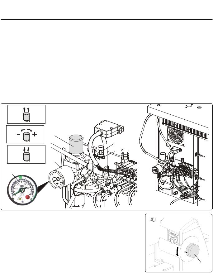
5. P O W E R A N D A I R C O N N E C T I O N
5.1.Simple connection of air lines are made by quick connector. Socket 25 KEAK 13 (order number FESTO 151776 - marking KD 1/4 - S, order number RECTUS 38044) is used as standard. Unithas corresponding input .
Input pressure must minimally be 1 bar (0,1 MPa) greater than output pressure set on regulator. The manufacturer recommends addition of a shut-off valve so that it is possible to close the air supply.
5.2.After air connection check, set the air pressure on the dial of the regulator. It should be in the range 0.45-0.6 MPa. To correct it: pull the stopper out. To increase the set pressure turn clockwise, to decrease, turn counterclockwise. Tighten the stopper again. The pressure for the cutting cylinders is set to 0.4 MPa (4bar) from manufacturer by screw and loosening the nut . If a material is incorrectly cut, check the cutting steel and a pressure on the regulator .
N o t e : Set lower air pressure for short cutting steels and higher air pressure for long cutting steels.


5.3.Power supply must be 208 to 230 volts 1 phase, 50 or 60 hertz. Receptacle plug must meet requirements of IEC standard
364-4-41, its circuit breaker must be minimal 10A with characteristic C according to the EN 60947-2 (or 16A with characteristic B). No other devices must not be connected to the circuit breaker of the socket. The hand wheel must turn counter clockwise.
The machine is equipped with a filters which contain
capacitors which generate an high frequency leakage current. In order to prevent nuisance tripping, residual current
protection device must be protected against these high frequency currents: this is the case for industrial residual current device (example „S“ type).
5.4. To add the LED lights - the provided warranty does not refer to the LED diodes.
1-14 Revised 03/2006 e-mail: service@amfreece.cz; parts@amfreece.cz; website: www.amfreece.com
Phones: +420 582 309 146 (Service); +420 582 309 286 (Spare Parts); Fax: +420 582 360 606
S-311
B - MACHINE ASSEMBLY
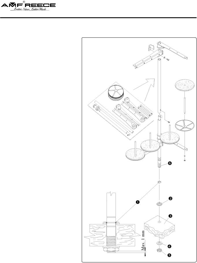
6. T H R E A D S TA N D I N S TA L L AT I O N
6.1. Put the thread stand together |
Picture 6.1. |
according to the drawing. |
|
6.2.Position of the locking ring allows assembly of the thread stand for various thickness of the table top. Threaded end of the postmust not extend more that 1 mm through the locking nut .
6.3.Insert the washer and the post into the hole provided in the right rear of the table top . Insert the washer and tighten the nut .
Revised 03/2006 |
1-15 |
e-mail: service@amfreece.cz; parts@amfreece.cz; website: www.amfreece.com
Phones: +420 582 309 146 (Service); +420 582 309 286 (Spare Parts); Fax: +420 582 360 606
S-311
B - MACHINE ASSEMBLY
7. L U B R I C AT I O N
7.1.There is the fank for oil eycess on the machine .
7.2.For oil tigthness and removal is important,that upper edge of the funnel inserted to the holder
was on bottom frame area lever and in holder socket was the rubber ring .

1-16 Revised 03/2006 e-mail: service@amfreece.cz; parts@amfreece.cz; website: www.amfreece.com
Phones: +420 582 309 146 (Service); +420 582 309 286 (Spare Parts); Fax: +420 582 360 606

S-311
C - PROPER APPLICATION
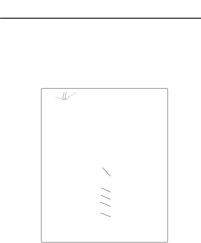
1 . P O W E R U P / H O M E P O S I T I O N
1.1.Turn the main power switch on by turning clockwise to the „ I“ position.
1.2.The display is activated and illuminated. The screen displays information about manufacturer and version of program installed in the machine. Wait until the main screen appears on the display.
1.3.If the error message E01 (machine is not in the home position) appears on the display press
the  button . If a different error message appears on the display - follow the Troubleshooting section.
1.4.The machine is ready for operation when Ready message appears on the display, in location .
(Display description is on the manual page no. 1-24).

|
|
Revised 03/2006 |
1-17 |
e-mail: service@amfreece.cz; parts@amfreece.cz; website: www.amfreece.com |
|
Phones: +420 582 309 146 (Service); +420 582 309 286 (Spare Parts); Fax: +420 582 360 606 |
|
S-311
C - PROPER APPLICATION
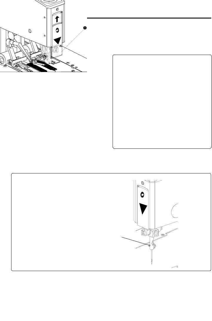
2 . N E E D L E I N S TA L L AT I O N
Use needles AMF Reece 02.0505.0.111/113…. Nm 90 – 1 10), loading  needle bard D = 2 mm. Needles 02.0558.1.112 are externally treated and needle shape is adapted for sewing thick material. Thicker needles is not possible to use for standard stitching plates.
2.1. Lift the transparent needle cover up .
Recommended Threads |
Needle System |
No. |
(Nm) |
120 |
90 |
90 |
90 — 100 |
80 |
90 — 110 |
2.2.Loosen the screw and remove the needle.
2.3.Insert the new needle so that the needle scarf A is on opposite side from screw of the tension. Do not install a bent or broken needle. Roll the needle on a flat surface to check for straightness.
2.4.Tighten the screw well.
1-18 Revised 03/2006 e-mail: service@amfreece.cz; parts@amfreece.cz; website: www.amfreece.com
Phones: +420 582 309 146 (Service); +420 582 309 286 (Spare Parts); Fax: +420 582 360 606
Loading...