


 Loading...
MODEL S-100
EYELET BUTTONHOLE MACHINE PARTS AND SERVICE MANUAL
MACHINE SERIAL No.
PART NUMBER 97. 1700.1.004
This manual is valid from the machine serial No.: J173961
AMF is trademark of AMF Group, Inc. |
02/ 2 0 0 6 |

Warranty Registration Card
(Please Fax or Mail immediately after installation)
Note: All Warranty Claims Void, unless Registration Card on file at AMF Reece HQ
Machine model number:
(S101, S100, S104, S211, Decostitch, S4000 BH, etc)
Manufacturer‘s serial or production number:
Installation Site Information:
Customer‘s Name:
Customer‘s Mailing Address:
Customer‘s Telephone Number:
Supervising Mechanic‘s or Technician‘s Name:
Signature of Supervising Technician:
AMF Reece Technician‘s Name:
AMF Reece Technician‘s Signature:
Type of garment produced at this location?
Average Daily Production Expected from this machine?
(number of buttonholes, jackets sewn, pants produced, buttons sewn, etc)
Any special requirements required at this location?
What other AMF Reece Machines are at this location?
How can we serve you better?
Tovární 582, 796 25 Prostìjov, Czech Republic
Fax: +420 582 360 606, e-mail: service@amfreece.cz, website: www.amfreece.com

LIMITED WARRANTY ON NEW AMF REECE EQUIPMENT
Warranty provisions:
A ninety (90) day limited service labor warranty to correct defects in installation, workmanship, or material without charge for labor. This portion of the warranty applies to machines sold as ”installed” only .
A one (1) year limited material warranty on major component parts to replace materials with defects. Any new part believed defective must be returned freight prepaid to AMF Reece, Inc. for inspection. If, upon inspection, the part or material is determined to be defective, AMF Reece, Inc. will replace it without charge to the customer for parts or material.
Service labor warranty period shall begin on the completed installation date. Material warranty shall begin on the date the equipment is shipped from AMF Reece, Inc.
Exclusions:
Excluded from both service labor warranty and material warranty are: (1) Consumable parts which would be normally considered replaceable in day-to-day operations. These include parts such as needles, knives, loopers and spreaders. (2) Normal adjustment and routine maintenance. This is the sole responsibility of the customer. (3) Cleaning and lubrication of equipment. (4) Parts found to be altered, broken or damaged due to neglect or improper installation or application. (5) Damage caused by the use of non-Genuine AMF Reece parts. (6) Shipping or delivery charges.
There is no service labor warranty for machines sold as ”uninstalled”.
Equipment installed without the assistance of a certified technician (either an AMF Reece Employee, a Certified Contractor, or that of an Authorized Distributor) will have the limited material warranty only. Only the defective material will be covered. Any charges associated with the use of an AMF Reece Technician or that of a Distributor to replace the defective part will be the customer’s responsibility.
NO OTHER WARRANTY, EXPRESS OR IMPLIED,AS TO DESCRIPTION, QUALITY, MERCHANTABILITY, and FITNESS FOR APARTICULAR PURPOSE, ORANYOTHER MATTER IS GIVEN BYSELLER OR SELLER’S AGENT IN CONNECTION HEREWITH. UNDER NO CIRCUMSTANCES SHALL SELLER OR SELLER’S AGENT BE LIABLE FOR LOSS OF PROFITS ORANY OTHER DIRECT OR INDIRECT COSTS, EXPENSES, LOSSES OR DAMAGESARISING OUT OF DEFECTS IN OR FAILURE OF THE EQUIPMENT ORANY PART THEREOF.
WHATTO DO IFTHERE ISAQUESTION REGARDINGWARRANTY
If a machine is purchased through an authorized AMF Reece, Inc. distributor, warranty questions should be first directed to that distributor. However, the satisfaction and goodwill of our customers are of primary concern to AMF Reece, Inc. In the event that a warranty matter is not handled to your satisfaction, please contact the appropriate AMF Reece office:
Europe/Africa/Americas |
Southwest Asia |
||
Prostejov, Czech Republic |
Istanbul, Turkey |
||
Phone: |
(+420) 582-309-275 |
Phone: |
(+90) 212-465-0707 |
Fax: |
(+420) 582-360-608 |
Fax: |
(+90) 212-465-0711 |
e-mail: |
service@amfreece.cz |
e-mail: |
amfreeceturkey@superonline.com |
Southeast Asia
Kowloon, Hong Kong Phone: (+852) 2787-2273
Fax: (+852) 2787-5642
e-mail: amfreece@netvigator.com

|
S100 |
|
TABLE OF CONTENTS |
|
|
A-INTRODUCTION |
|
|
1. Introduction .......................................................................................................................... |
1-1 |
|
2. Specifications ........................................................................................................................ |
1-2 |
|
3. Safety of work ...................................................................................................................... |
1-3 |
|
4. Security of the operator and maintenance ............................................................................... |
1-4 |
|
5. List of the safety labels and devices ....................................................................................... |
1-6 |
|
6. Position of the labels and the safety devices ........................................................................... |
1-7 |
|
B - MACHINE INSTALLATION |
|
|
1. Content of the shipping box ................................................................................................... |
1-8 |
|
2. Accessories. ......................................................................................................................... |
1-8 |
|
3. Machine unpacking and assembling ....................................................................................... |
1-9 |
|
4. Adjustment of the T - Belt tension for sewing ......................................................................... |
1-12 |
|
5. Adjustment of the left T - belt tension ..................................................................................... |
1-13 |
|
6. Thread stand installation. ....................................................................................................... |
1-14 |
|
C - OPERATOR INSTRUCTIONS |
|
|
1. Preparing to Sew .................................................................................................................. |
1-15 |
|
2. Needle Installation ................................................................................................................ |
1-16 |
|
3. Threading ............................................................................................................................. |
1-16 |
|
D - MACHINE ADJUSTMENTS |
|
|
1. Stitches density adjustment .................................................................................................... |
1-19 |
|
2.Adjustment of the stitches density in the eye ........................................................................... |
1-22 |
|
3. Adjustment of the stitches density in cross bar ........................................................................ |
1-22 |
|
4. Lengths of the sewing ............................................................................................................ |
1-23 |
|
5. Change of the buttonhole shape - change of the lateral cam .................................................... |
1-24 |
|
6. Change of the width bite ........................................................................................................ |
1-25 |
|
7. Principles of sewing ............................................................................................................... |
1-28 |
|
8. Bed plate alignment ............................................................................................................... |
1-34 |
|
9. Testing the cam position ........................................................................................................ |
1-34 |
|
10. Turning mechanism .............................................................................................................. |
1-35 |
|
11. Stopping mechanism ............................................................................................................ |
1-37 |
|
12. Setting - up the mechanism for fabric clamping ..................................................................... |
1-39 |
|
13. Clamp plate spreading ......................................................................................................... |
1-40 |
|
14. Length setting - up of the second buttonhole row ................................................................. |
1-41 |
|
15. Eye shape control ............................................................................................................... |
1-41 |
|
16. Needle bar height ................................................................................................................ |
1-42 |
|
17. Clearance Between the Looper and the Needle ................................................................... |
1-43 |
|
18. Spreaders adjustment .......................................................................................................... |
1-44 |
|
19. Loopers movement ............................................................................................................. |
1-45 |
|
Revised 10/2005 |
|
|
e - mail service @amfreece.cz, parts @amfreece.cz, website: www.amfreece.com |
1-9 |
|
Phones: +420 582 309 146 (service), +420 582 309 286 (spare parts), Fax +420 582 360 606 |
||
|

S100
TABLE OF CONTENTS
20. Setting - up of the spreaders movement ............................................................................... |
1-48 |
21. Cutting lever and anvil ......................................................................................................... |
1-49 |
22. Knife and Cutting Steel change ............................................................................................ |
1-50 |
23. Cutting space modification ................................................................................................... |
1-52 |
24. Cut Before and Cut After .................................................................................................... |
1-53 |
25. Knife adjustment for upper thread trim ................................................................................. |
1-54 |
26. Thread draw off mechanism ................................................................................................ |
1-56 |
E - ROUND EYE ADJUSTMENTS |
|
1. Introduction .......................................................................................................................... |
1-57 |
2. Different position of the machine mechanisms ......................................................................... |
1-57 |
3. Stop motion control .............................................................................................................. |
1-58 |
4. Round Eye Machine Eyelet Diameter or Cutting Space Change .............................................. |
1-59 |
5. Clamp feet using for correct buttonhole sewing ...................................................................... |
1-59 |
6. Adjustment of the supplied accessories .................................................................................. |
1-60 |
F - MACHINE ADJUSTMENT - CROSS BAR |
|
1. Introduction. ......................................................................................................................... |
1-61 |
2. Different position of the machine mechanisms ......................................................................... |
1-61 |
3. Cross bar relationship to the first and second row of the stitches ............................................. |
1-61 |
4. Device for sewing the cross bar ............................................................................................. |
1-62 |
5. Readjustment of the cross bar machine to machine without bar ............................................... |
1-64 |
6. Readjustment of the cross bar machine to the fly bar machine ................................................. |
1-64 |
7. Hand feeding ........................................................................................................................ |
1-64 |
8. Cross bar length adjustment ................................................................................................. |
1-65 |
9. Correction of the cross bar position in axis X ......................................................................... |
1-66 |
10. Cam assembly installation .................................................................................................... |
1-66 |
11. Change of the machine rotation ............................................................................................ |
1-67 |
G - MACHINE MAINTENANCE |
|
1. Cleaning and maintenance the machine ................................................................................... |
1-68 |
2. Periodic maintenance ............................................................................................................ |
1-69 |
3. Machine lubrication ............................................................................................................... |
1-70 |
4. Machine disposal .................................................................................................................. |
1-71 |
H - DOCUMENTATION |
|
1. Electrical diagrams ................................................................................................................ |
1-72 |
Revised 10/ 2005 1-10 e - mail service @amfreece.cz, parts @amf reece.cz,website: www.amfreece.com Phones: + 420 582 309 146 ( service), + 420 582 309 286 (spare parts), Fax : + 420 582 360 606

S100
A - INTRODUCTION
1 . I N T R O D U C T I O N
The S100-030/031/032 (AF-CB/CA-RE) is a versatile two thread chain stitch sewing machine for sewing buttonholes with possibility to insert the gimp. The regular eye, Cut Before / CutAfter, adjustable flybar machine may be used for suits, jeans and a wide variety of sewing applications.
The S 100-052/053 (RE) is two threads, pertinently one thread machine, which is sewing round chain stitch buttonhole. It is used for sewing decorative buttonholes, for example on the hoods or hats.
The S 100-060 (CRB) is two threads machine with chain stitch and opportunity insert the gimp for sewing buttonholes with cross bar and flybar. It allows sewing by one chain thread stitch, which is suitable for smaller highlighting of the stitches above the fabric (smaller plasticity).
The size of the buttonhole (with eye or without eye) and type of the buttonhole end (open end, flybar or cross bar) are ensured by changeable cams.
The semiautomatic lubrication system uses drip oil wicks to lubricate the critical machine areas.
To prevent machine damage, it is possible to check the level of oil in the visibly placed oil sight gauge .
Machine models:
S100 - 030 /031/032
S100 - 030
S100 - 031
S100 - 032
S100 - 052
S100 - 053
S100 - 060
AF-CB/CA-RE for standard sewing for jeans sewing for textilie sewing RE (Small eye) RE (Large eye) CRB
Note: |
|
|
AF |
- |
Adjustable Flybar |
CB |
- |
Cutting Before |
CA |
- |
Cutting After |
CRB - |
Cross Bar |
|
RE |
- |
Round Eye |
All these machines have cut upper thread mechanisms.
Revised 10/2005
e-mail: service@amfreece.cz ; parts@amfreece.cz ; website: www.amfreece.com 1-1 Phones: +420 582 309 146 (Service), +420 582 309 286 (Spare Parts); Fax: +420 582 360 606

2-1
+420 (Service), 146 309 582 +420 Phones: |
; cz.service@amfreece mail:-e |
606 360 582 +420 Fax: Parts); (Spare 286 309 582 |
com.amfreece.www website: cz;.parts@amfreece |
10/2005 Revised
Machine Type |
S100 - 030 |
|
S100 - 033 |
|
S100 - 035 |
S100 - 036 |
|
|
S100 - 060 |
|
|
S100 - 052 |
|
|
S100 - 053 |
|
|
|
|
|
|
|
|
|
Eyelet buttonhole machine for sewing the |
|
|
|
|
|
|
Description |
|
|
Eyelet Buttonhole Machine |
|
|
|
|
|
Eyelet buttonhole machine for sewing |
||||||
|
|
|
|
|
buttonholes with the cross bar and flybar |
|
|
the regular eye buttonholes |
|||||||
|
|
|
|
|
|
|
|
|
|
|
|||||
Buttonhole style |
|
|
|
|
|
|
|
|
|
|
|
|
|
|
|
Sewing speed |
|
|
1768 ± 5% stitches/min |
|
|
|
1450 ± 5% stitches/min |
|
|
1768 ± 5% stitches/min |
|||||
Buttonhole Length |
10 - 38 mm (0.4 - 1.5") without upper thread trimming, |
|
|
13-32 mm |
|
|
|
- |
|||||||
10 - 32 mm (0.4 - 1.26") with upper thread trimming |
|
|
|
|
|
||||||||||
|
|
|
|
|
|
|
|
|
|
||||||
Stitch Density |
|
|
|
|
|
6-16 |
|
stitches /cm (15-41 stitches /inch) |
|
|
|
|
|
|
|
|
|
|
|
|
|
|
|
|
|
|
|||||
|
|
|
|
|
|
8 |
|
|
|
|
|
|
|
|
|
Bite Range |
|
|
|
|
|
|
|
|
2 - 4 mm |
|
|
|
|
||
Cord Trim |
- |
|
|
|
yes |
|
|
|
|
|
- |
||||
|
|
|
|
|
|
- |
|
|
|
||||||
Eye Type |
|
|
without eye, 2.2 x 3.0 mm (0.086 x 0.118"); |
|
3.2 x 5.0 mm (0.126 x 0.197") |
|
|
2.5; 3; 3.5; 4 |
|
|
3.5; 4; 5; 6; 7 |
||||
|
|
|
|
|
|
||||||||||
Flybar Length |
|
|
|
|
standard 6 mm (possible range 3.0 - 7.0 mm) |
|
|
|
|
|
|
||||
|
|
|
|
|
|
|
- |
||||||||
Flybar Density |
|
|
|
|
8 6 - 16 stitches / cm |
|
|
|
- |
||||||
Number of stitches in the eye |
|
|
|
- |
|
|
|
8 - 16 stitches/cm |
|
|
|
- |
|||
Cross Bar Length |
|
|
|
|
|
|
4 - 8 mm |
|
|
|
|||||
|
|
|
|
|
|
|
|
||||||||
Cross Bar Density |
|
|
|
- |
|
|
|
86 - 16 stitches / cm |
|
|
|
- |
|||
Clamp Foot Height |
|
|
|
|
|
|
|
|
10 mm (0.4") |
|
|
|
|
|
|
|
|
|
|
|
|
|
|
|
|
|
|
|
|||
Maximum work thickness |
|
|
|
|
|
|
|
|
max 6 mm (1/4") |
|
|
|
|
||
Buttonhole Cutting Mode |
|
|
|
|
standard cutting after (CA), possible setting cutting before (CB) |
|
|
|
|
||||||
Cutting Space |
|
|
|
|
standard 0.5 - 0.7 (minimum 0.1; maximum 1.4) |
|
|
|
- |
||||||
|
|
|
|
|
|||||||||||
Needle system |
|
|
|
|
|
02.0501.0.111 (1807 D Nm 100 - standard) |
|
|
|
|
|
|
|||
|
|
|
|
|
|
|
|
|
|
||||||
|
|
|
|
|
|
|
|
|
|
|
|
|
|
|
|
|
|
|
|
|
02.0503.3.113 (1807 D Nm 110-130 - thick fabric) |
|
|
|
|
||||||
|
|
|
|
|
|
|
|
|
|
||||||
* Recommended threads |
|
|
|
|
|
|
|
|
Size 80,100,120 |
|
|
|
|
||
Operating Conditions |
|
|
according to IEC 364-3, IEC 364-5-51 temperature from +5° to 40°C, relative air humidity from 30 to 80 % |
|
|
|
|||||||||
Air Pressure |
- |
|
|
|
5.6 bar (80 psi) |
|
|
|
- |
|
|
|
- |
||
|
|
|
|
|
|
|
|||||||||
Machine db Level |
|
|
|
|
|
|
|
|
|
|
|
|
|
|
|
|
|
|
|
|
|
from 75 to 81 dB at max. speed |
|
|
|
|
|||||
Machine Head Dimension |
|
|
|
|
600 mm (23.6") - height x 465 mm (18") - length x 530 mm (21") - width |
|
|
|
|
||||||
Machine Head Weight |
|
|
64 kg (143 lb) |
|
|
|
66 kg |
|
|
64 kg (143 lb) |
|||||
|
|
|
|
|
|
||||||||||
Table Dimension |
|
|
|
|
780 mm (31") - height |
|
x 1100 mm (43") - length x 600 mm (23.6") - width |
|
|
|
|
|
|
||
|
|
|
|
|
|
|
|
|
|||||||
Machine Weight |
|
|
149 kg |
|
|
|
151 kg |
|
|
|
149 kg |
||||
|
|
|
|
|
|
|
|||||||||
Electrical Requirements |
|
|
1NPE~60Hz 110V/TN/S ; 3NPE~60Hz |
|
|
|
|
|
|
|
|||||
|
|
|
230V/TN/S ; 1NPE~50Hz 230V/TN/S ; 3NPE~50Hz 400V/TN/S |
|
|
|
|||||||||
|
|
|
|
|
|
|
|
|
|
|
|
|
|
|
|
* Note: If a customer uses thread size 100 and less, the manufacturer recommends to use the left looper 17.0069.4.019
SPECIFICATIONS . 2 |
S100 |
INTRODUCTION - A

S100
A - INTRODUCTION
3 . I N S T R U C T I O N F O R S A F E T Y O F W O R K
The sewing machine S -100 is designed and produced to be highly reliable. Special attention is given for securing of the service simplicity and effective safety protection of the operators and machine maintenance.
The machine S -100 has safety appliance which protects operator but also machine and respects valid safety and hygienic rules for usual technological using of the machine. These safety appliances include plug of supply, operating switch (circuit breaker) and covers.
There are safety labels placed on the machine for warning for supplementary danger. Do not remove and damage these labels. When the label is damaged, order the new one. The said precautions can not cover all safety aspects that is why operator before using of the machine has to read and understand to this instructions. The mistakes will be eliminated during machine installation and during its own operation. Do not try to put the machine into operation without reading all the machine instructions and until well understanding to every function and progress.
There are three types of safety direction in these instructions:
D A N G E R ! Possible loss of life.
WA R N I N G ! Possible serious injury or machine damage.
N O T I C E ! Possible injury or machine damage.
It is recommended to service workers fromAMF Reece oversaw to the installation and initial training of mechanics and operators.
Strictly given safety program, which part is the direction for safety operation, is the most effective security of the workers safety during the operating with the machine. The secure work with the machine is ensured by the safety covers which are useful, if they are mounted and fixed correctly. The warning labels and service must be done according to the instructions. Operators and service workers should wear safety goggles.
Revised 10/2005
e-mail: service@amfreece.cz ; parts@amfreece.cz ; website: www.amfreece.com 1-3 Phones: +420 582 309 146 (Service), +420 582 309 286 (Spare Parts); Fax: +420 582 360 606

S100
A - INTRODUCTION
4 . I N S T R U C T I O N S F O R T H E S E C U R I T Y O F T H E O P E R ATO R A N D M A I N T E N A N C E
When the machine is set to the working area, it is recommended to keep the minimal distance said in the drawing.
D A N G E R !
-Before machine connection to the power make sure, whether all safety covers are mounted.
-If it is necessary to remove some safety covers, switch off the operating switch (circuit breaker) and disconnect the machine by the fork of supply from the socket.
-Do not connect the machine to the power if some cover is removed.
WA R N I N G !
-Remember the position of the operating switch (circuit breaker) so that is possible use it from the arbitrary position.
-Make sure, whether supply of energy and its dimensioning and safeguarding allows permanent supply of energy needed for dependable output of the machine.
-Do not forget to persuade yourself before fork connection to the socket whether both switches on the machine are switched off.
-Check if the electrical cables are not damaged, so that be touch with uncovered conductor, can not occur any injury.
-Check regularly if the safety covers are correctly mounted and whether they are not damaged.
-When the covers are demaged, repair or replace them immediately for the new ones.
-Do not switch the machine on without covers.
-Do not touch rotary shafts by hands.
-In any circumstance, do not put hands to the needle space.
Revised 10/2005 1-4 e-mail: service@amfreece.cz ; parts@amfreece.cz; website: www.amfreece.com Phones: +420 582 309 146 (Service), +420 582 309 286 (Spare Parts); Fax: +420 582 360 606

S100
A - INTRODUCTION
-Before changing the needle, switch off the operating switch (circuit breaker).
-In case when the operator will not work on the machine, disconnect the power supply by removing the plug from the socket.
-Before cleaning or any maintenance work on the machine, disconnect the power supply by removing the plug from the socket.
-Do not adjust the machine in any way, which could endanger its safety.
-Every part of the machine can be dangerous, if there is incorrect manipulation or faulty maintenance with the machine That is why everybody, who will manipulate, maintain or operate with this machine must be acquainted with informations included in this manual.
C A U T I O N !
-Perform all regular service as described by this manual.
-If there is any problem with power supply, turn off the mine power switch (circuit breaker).
-Do not remove, paint over, damage or any way change safety labels. If a safety labels are lost or cannot be easily read, order the new one in our factory and place them on the original place.
-Long hair and loose clothing may be dangerous near any machinery.Always contain long hair and avoid loose clothing, so that it cannot be caught by machinery and cause injury.
-Never use this machine while under the influence of drugs or alcohol.
-If anything seems to be operating incorrectly in the machine call for maintenance assistance immediately.
-Be sure that there is adequate light for safe operation.Anormal minimum light level is 750 Lux.
Revised 10/2005
e-mail: service@amfreece.cz ; parts@amfreece.cz ; website: www.amfreece.com 1-5 Phones: +420 582 309 146 (Service), +420 582 309 286 (Spare Parts); Fax: +420 582 360 606
S100
A - INTRODUCTION
5 . L I S T O F T H E S A F E T Y L A B E L S A N D D E V I C E S
0.45 - 0.50 MPa
Standard label.
Marking of the air pressure (just for S 100 - 033, S 100 - 035 and S 100 - 036). Rotational direction (located on the right cover, left side of the rear cover, motor).
Warning by the cover removing (front cover of the frame, right cover of the drive, rear folding cover, motor cover).
Label of the safety conductor clip.
Necessity of the safety goggles using (sewing head front part, above the needle). External covers of the machine folding or dismantling by the tools.
Guard of the upper end of the needle bar. Fixed guard of the needle area.
Folding transparent eye guard - in front of the needle area.
Axis of the tilting head located irregularly to the driving axis. This solution ensure withdrawing of the belts from the driving pulleys for lifting of the head for cleaning and maintenance work . When the motor is switched on, the mechanisms of the sewing head will not move.
Folding front cover, which precludes the fingers inserting between the moving working board and the fixed frame.
Revised 10/2005 1-6 e-mail: service@amfreece.cz ; parts@amfreece.cz; website: www.amfreece.com Phones: +420 582 309 146 (Service), +420 582 309 286 (Spare Parts); Fax: +420 582 360 606

S100
A - INTRODUCTION
6 . P O S I T I O N O F T H E L A B E L S A N D T H E S A F E T Y D E V I C E S
8 |
6 |
|
Machine head |
|
|
1 |
|
|
Locking |
12 |
|
screw |
||
|
||
4 |
10 |
|
|
||
3 |
|
|
Folding |
9 |
|
rear cover |
Table |
|
12 |
||
|
||
|
Front cover of the frame |
|
2 |
4 |
|
|
||
|
Frame |
|
Bedplate |
5 |
|
3 |
|
WA R N I N G ! When the machine works, it is not disabled to give the fingers to the space between the machine table and machine head in marked place. When the working board moves, the clearance in this place is about 50 mm. If fingers are accidentally put into this place, it can occur very serious injury.
Front cover of the frame and lock screw of the folding rear cover, which disable tilting of the rear cover, are dismantled during transport. It is necessary to install these safety parts to the machine before the machine is switched on.
CAUTION! If it is necessary to lift the head out of the home position, it is necessary to tilt the folding front cover to the operator side, then put the head back. If this process is not kept, and the machine is switched on, the cover will be damaged.
Revised 10/2005
e-mail: service@amfreece.cz ; parts@amfreece.cz ; website: www.amfreece.com 1-7 Phones: +420 582 309 146 (Service), +420 582 309 286 (Spare Parts); Fax: +420 582 360 606

S100
B - MACHINE INSTALLATION
1 . C O N T E N T O F T H E S H I P P I N G B O X
1.The delivery usually contains two boxes. One box contains the table and wiring, second the head of machine.
2.The box contain also carton with accessories and operation instruction with spare parts manual and the thread stand .
3.When unpacking the delivery, follow labels which are on the cover.
C A U T I O N ! If the delivery was damaged during the transport, inform the carrier. Check the contains of the delivery with order. In case that there are some faults, immediately inform
the manufacturer - later complains will not be taken into consideration!
2 . A C C E S S O R I E S
Free accessories are supplied with the machinethe list is mentioned in this manual.
S100 |
- |
030 |
- accessories 030 (standard) - see 3-32 and it is possible to order 031, 032 |
||
S100 |
- |
031 |
- accessories 031 (jeans) |
- see 3-34 and it is possible to order 030, 032 |
|
S100 |
- |
032 |
- accessories 032 (textile) |
- see 3-36 and it is possible to order 030, 031 |
|
S100 |
- |
052 |
- accessories Round Eye (Small) |
- see 3-52 |
|
S100 |
- |
053 |
- accessories Round Eye (Large) |
- see 3-54 |
|
S100 |
- |
060 |
- accessories CRBsee 3 - 67 |
|
|
Revised 10/2005 1-8 e-mail: service@amfreece.cz ; parts@amfreece.cz; website: www.amfreece.com Phones: +420 582 309 146 (Service), +420 582 309 286 (Spare Parts); Fax: +420 582 360 606

S100
B - MACHINE INSTALLATION
3 . M A C H I N E U N PA C K I N G A N D A S S E M B L I N G
1.After unpacking it is necessary to put the table together according to the enclosed documentation. Delivered table is standardly took apart. For connection of the table frame, use enclosed connecting parts. For ensuring of the conductive connection among all metal parts of the table is necessary to put fan washers under the one of the two neighboring screws.
WA R N I N G ! Integrity of the protective connection of the machine metal parts must be kept according to the section DOCUMENTATION - Wiring diagrams.
C A U T I O N ! The wiring assembly can perform only the person, who has an appropriate electrical qualification.
2.After putting the table together and wiring the assembly - before motor cover mounting, install the table to the given place. Its stability is ensured by the rear abutment, which is controlled by the manual screw.
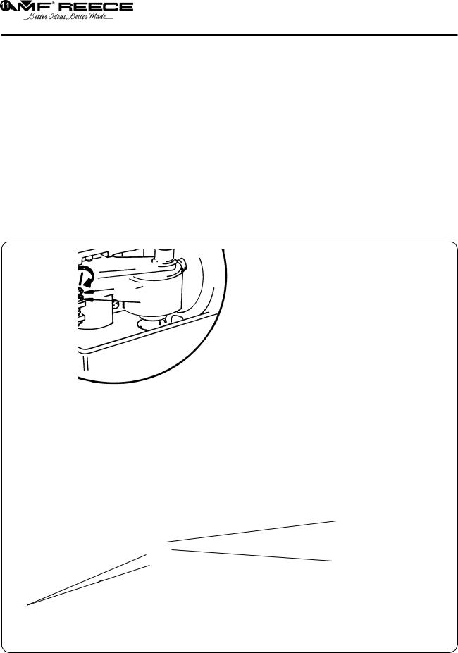
3.Before next assemblies of the machine, it is necessary to control if the motor turns in right direction, it is marked S on drawing. The plug of supply, which is used as a main switch, put into the socket. When the operational switch (circuit breaker) is switched on, activate the motor to run by the
foot pedal. Check the right rotational direction of the pulley according to the arrow placed on the motor. Incorrect rotational direction of the electric motor can cause machine damage.
|
LEFT VIEW |
Rotational direction |
Operator |
Motor |
|
Revised 10/2005
e-mail: service@amfreece.cz ; parts@amfreece.cz ; website: www.amfreece.com 1-9 Phones: +420 582 309 146 (Service), +420 582 309 286 (Spare Parts); Fax: +420 582 360 606
S100
B - MACHINE INSTALLATION
WA R N I N G ! It is commended to use original table, part number 04.90.17.0.xxx, for delivered machine. If the user has to use another table, producer can not take the responsibility for possible troubles. In this case it is necessary to use such equipment, which allows to reach on the left driving pulley for the machine cycle max. 250 rev./min. and on the right pulley for sewing drive max 875 rev./min. Higher revolution can cause serious machine damage! The socket for plug of power supply has to comply with requirements of norm IEC 364-4-41.
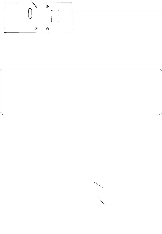
4 . |
Insert tall rubber washers from the accessories to the four holes on the table board. |
Rubber washers
Upper view
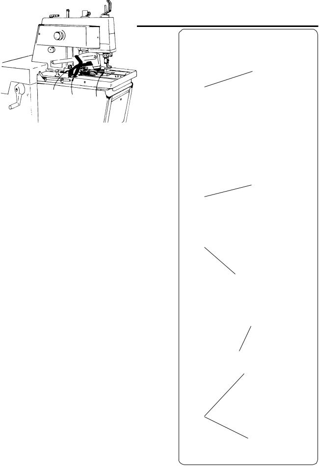
5 . |
When the head from the cover is taken out, clean the head from the preservative grease. To catch the |
|
machine during the manipulation, use slots in front and back of the machine frame. |
6 . |
The removed machine head place on the installed rubber washers and according to the drawing fix it |
|
by the screws, washers and rubber washers to the table. |
C A U T I O N ! Do not take the machine head in the machine table!
Screws Washers Small rubber washers
Tall rubber washers
Oil spool
Revised 10/2005 1-10 e-mail: service@amfreece.cz ; parts@amfreece.cz; website: www.amfreece.com Phones: +420 582 309 146 (Service), +420 582 309 286 (Spare Parts); Fax: +420 582 360 606

S100
B - MACHINE INSTALLATION
7 . |
Fold the rear covers and tilt the head in the frame, make rear screws accessible during the assembly. |
|
Since some deliveries can have the covers partly dismantled, fix them to their place by using drawings |
|
in parts manual.All safety covers must be assembled according to the section: I N T R O D U C |
|
T I O N - Position of labels and safety equipment. |
8 . |
Oil reservoir should be placed between installed tall rubber washers. |
9 . |
The installation of the right driving belt (longer) is done by loosening the screw of the right cover and |
|
its removal. |
1 0 . |
If the left drive belt is not put on the upper pulley of the head (tilting the rear cover to have the access |
|
to this belt), after loosening the inner screw of the frame, it is necessary to make adequate space |
|
between the gear of the hand drive and the gear of the rear shaft by tilting the frame. |
11 . |
After belt installation, tighten the frame inner screw again so that both gears fit in, use the |
|
hand wheel. |
|
If the belts are correctly mounted, they will not touch the covers or bedplate. |
|
C A U T I O N ! After installing the belts, install the motor cover. It is necessary to connect the cover, |
|
machine head and motor by the protective circuit breaker. |
1 2 . |
Before operating the machine, install the clip and the screw from the accessories on the rear |
|
cover. |
Folding rear cover
Rear shaft gear
Inner screw of the frame
Hand drive gear
Frame
Revised 10/2005
e-mail: service@amfreece.cz ; parts@amfreece.cz ; website: www.amfreece.com 1-11 Phones: +420 582 309 146 (Service), +420 582 309 286 (Spare Parts); Fax: +420 582 360 606

S100
B - MACHINE INSTALLATION
4 . A D J U S T M E N T O F T H E T - B E LT T E N S I O N F O R S E W I N G
The driving belt is placed under the right side cover.After its dismantling, loosen the pulley screw and adjust the V - belt pulley so that, so that during pushing on the front branch of the belt, there should be a sag about 25 mm (1”), as illustrated. Tighten the screw of the idler pulley.
For easy folding of the machine head, the pulley must be down with tilt min. 30° backwards. Install the removed cover again.
Idler pulley
Correct belt deflection
Revised 10/2005 1-12 e-mail: service@amfreece.cz ; parts@amfreece.cz; website: www.amfreece.com Phones: +420 582 309 146 (Service), +420 582 309 286 (Spare Parts); Fax: +420 582 360 606

S100
B - MACHINE INSTLLATION
5 . A D J U S T M E N T O F T H E L E F T T- B E LT T E N S I O N
1 . |
The access to the belt will be obtained after folding of the folding rear cover. |
2 . |
Then adjust the idler pulley until 13 mm, (1/2”) of flex is obtained in the belt, as illustrated. |
3 . |
Tighten the idler pulley locking screws. |
4 . |
Install the motor covers and set the belt stud, which is fixed on the motor cover to the distance 3 mm, |
|
(1/8”) below the pulley. This belt stud will prevent dropping of the belt when the machine head is |
|
lifted. |
5 . |
Install the removed covers again. |
Idler pulley
13 mm, (1/2")
Motorcover
3 mm, (1/8")
Belt stud
Idler pulley locking screw
Revised 10/2005
e-mail: service@amfreece.cz ; parts@amfreece.cz ; website: www.amfreece.com 1-13 Phones: +420 582 309 146 (Service), +420 582 309 286 (Spare Parts); Fax: +420 582 360 606

S100
B - MACHINE INSTALLATION
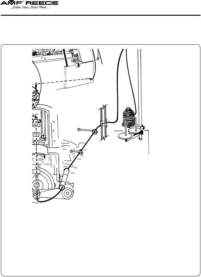
6 . T H R E A D S TA N D I N S TA L L AT I O N
1 . |
Put the thread stand together |
|
according to the drawing. |
2 . |
Position of the locking ring |
|
allows assembly of the thread stand |
|
for various thickness of the table |
|
top. Threaded end of the post |
|
must not extend more that 1 mm |
|
(1/32) through the locking nut . |
3 . |
Adjust the ring , insert the washer |
|
and the post into the hole |
|
provided in the right rear of the |
|
table top . Insert the washer |
|
and tighten the nut . |
Revised 10/2005 1-14 e-mail: service@amfreece.cz ; parts@amfreece.cz; website: www.amfreece.com Phones: +420 582 309 146 (Service), +420 582 309 286 (Spare Parts); Fax: +420 582 360 606
C - OPERATOR INSTRUCTIONS
1 . P R E PA R I N G TO S E W
1.Read through all safety instructions and ensure all covers are installed.
2.Only Cord Trim - Check on the air pressure regulator that pressure is in range 4.5 - 5 bars (0.45 - 0.50 MPa), see note above the regulator.
3.Give oil to the manual oiling points and check the correct oil quantity in oil level indicator.
4.Check the needle and gimp threads are correctly threaded.
5.Before the first sewing, insert piece of fabric similar to sewing work under the clamp feet.
6.Insert the input cable into socket and by switching on of the operating switch (circuit breaker) switch the motor on.
7.Drive of the machine is activated by the table foot
pedal .
C A U T I O N ! To make sure the machine is sewing correctly, it is recommended to sew a few buttonholes on a scrap piece of material before sewing on a quality garment.
8.Insert the material under the clamp feet.
9. |
To lower the clamp feet |
, move the lever |
|
|
forward. |
|
|
10. |
Press the starting lever |
, the clamp feet are |
|
|
automatically lowered.After the buttonhole is sewn |
||
|
and cut, the clamp feet are raised. |
||
11. |
If the emergency stop button |
is pressed and held |
|
during sewing, the clamp feet will not raise at the end of the sewing cycle and it is possible to sew the buttonhole again.
12.If it is necessary to interrupt the sewing cycle press
the stop lever . The machine will finish the cycle without sewing and the clamp foot will raise. (if the stop lever is pressed and then emergency stop is pressed the machine will finish the cycle without clamp raising. It is not valid for S 100 - CRB - see section G 7.
13.To stop the machine immediately in any place of sewing cycle, press foot pedal (by heel down the sewing cycle is stopped, by toe the sewing cycle is started.
14.To start the sewing cycle without sewing, lift the
lever and after the cycle is started, the machine makes cycle without sewing.
Revised 10/2005
e-mail: service@amfreece.cz ; parts@amfreece.cz ; website: www.amfreece.com
Phones: +420 582 309 146 (Service), +420 582 309 286 (Spare Parts); Fax: +420 582 360 606
S100
1-15
S100
C - OPERATOR INSTRUCTIONS
2 . N E E D L E I N S TA L L AT I O N
1. |
Loosen needle locking screw and dismantle the original needle. |
2. |
Insert the new needle, so that the needle flat A is on opposite side from screw of the tension. Do |
|
not install a bent or broken needle. Roll the needle on a flat surface to check for straightens. |
|
The good quality needle does not have a deflection of the point. |
3. |
Tighten the needle locking screw well. |
3 . THREADING
WA R N I N G ! Check if the operating switch (circuit breaker) is switched off.
Thread the thread, as illustrated.
The appearance and quality of the buttonhole may be affected by one or more of the following
-stitches density
-used thread strength, colour
-thread elasticity
-used sewn material
-tension of upper and lower thread
-used thread thickness
-width of stitches
-choosen sewing thechnological procedure
Revised 10/2005 1-16 e-mail: service@amfreece.cz ; parts@amfreece.cz; website: www.amfreece.com Phones: +420 582 309 146 (Service), +420 582 309 286 (Spare Parts); Fax: +420 582 360 606

S100
C - OPERATOR INSTRUCTIONS
Threading the gimp and upper thread to the machine - S 100-030/031/032/033/035/036/052/053
To change the upper thread tension, use the nut .
Upper thread
Gimp thread
To adjust the gimp tension on the machine S 100 - 060 (CRB) use the screw .
Revised 10/2005
e-mail: service@amfreece.cz ; parts@amfreece.cz ; website: www.amfreece.com 1-17 Phones: +420 582 309 146 (Service), +420 582 309 286 (Spare Parts); Fax: +420 582 360 606
S100
C - OPERATOR INSTRUCTIONS
L o w e r t h r e a d
Use the manual nut to change the lower thread tension.
 Lowerthread
Revised 10/2005 1-18 e-mail: service@amfreece.cz ; parts@amfreece.cz; website: www.amfreece.com Phones: +420 582 309 146 (Service), +420 582 309 286 (Spare Parts); Fax: +420 582 360 606
S100
D - MACHINE ADJUSTMENT
1 . S T I T C H E S D E N S I T Y A D J U S T M E N T - S T R A I G H T S E C T I O N
a ) m a c h i n e m o d i f i c a t i o n S 1 0 0 - 0 3 0 / 0 3 3 / 0 3 5 / 0 3 6 / 0 5 2 / 0 5 3
1.Remove auxiliary rear cover.
2. |
Loosen the stud nut . |
|
3. |
Shift the rod stud |
in direction 1 to increase the stitch density, in direction 2 to decrease stitch |
|
density. |
|
4. |
Tighten the nut . |
|
N o t e : The limiter is installed on the lever . To obtain the stitch density 8-9 stitches/cm, shift the rod stud towards the limiter. To decrease the density, remove the limiter .
1 2
1
2
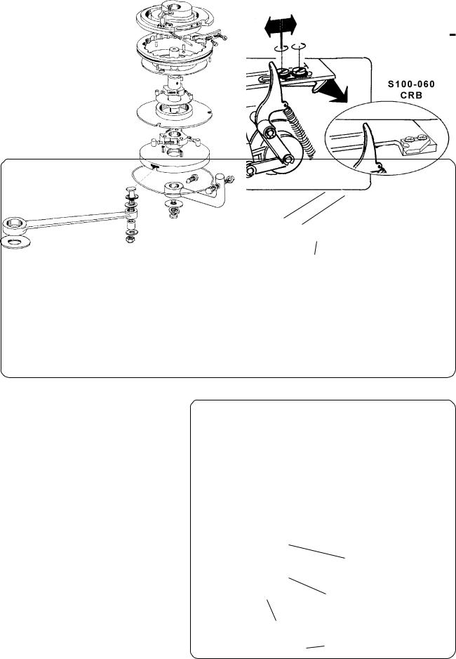
b ) m a c h i n e m o d i f i c a t i o n S 1 0 0 - 0 6 0
1.Fold the rear cover.
2.Start to sew the buttonhole, and stop the
|
machine at the moment, when the lever |
is |
|
shored up to screw . |
|
3. |
Loosen the nut and shift the lever |
in the |
|
slot. To decrease the density move the lever up, |
|
|
to increase the density move the lever down. |
|
4. |
Tighten the nut . |
|
Revised 10/2005
e-mail: service@amfreece.cz ; parts@amfreece.cz ; website: www.amfreece.com 1-19 Phones: +420 582 309 146 (Service), +420 582 309 286 (Spare Parts); Fax: +420 582 360 606

S100
D - MACHINE ADJUSTMENT
Wa r n i n g : When the machine is used for long time, the stitch density can be changed because of the running of the main cam brake and main shaft brake. That is why it is necessary to adjust the brakes.
A d j u s t i n g m a i n c a m b r a k e
The main cam brake controls the density of stitches which is adjust in chapter 2. It is a producer specification for setting the distance between stitches. Under normal use, the brake band will need to be adjusted again. The reason is to run in the brake band:
1. |
Loosen the locking nuts . |
|
2. |
By rotating the nuts is moving the brake band |
(in direction 4 to increase the break pressure, |
|
move the brake band in direction 3 to decrease the pressure). |
|
3. |
Tighten the locking nuts . |
|
CAUTION! If the main cam brake pressure is excessively high, the machine may malfunction. The brake pressure is used for easy breaking of the main cam brake, so that the main cam brake is not moving itself by rotary inertia.
H E L P : Adjust the stitch density according to the chapter 2 to require density with loosen the brake. Then lightly pull the brake, so that the number of stitches increase maximally to one stitch of length of the buttonhole. This will ensure correct function of the brake.
2
1
1.6 mm 0.063"
3 4
Revised 10/2005 1-20 e-mail: service@amfreece.cz ; parts@amfreece.cz; website: www.amfreece.com Phones: +420 582 309 146 (Service), +420 582 309 286 (Spare Parts); Fax: +420 582 360 606
S100
D - MACHINE ADJUSTMENT
A d j u s t m e n t o f t h e m a i n s h a f t b r a k e
The main shaft brake equalizes the stitch density of the buttonhole seam for the left and right-hand sides.
1. |
Loosen the locking nut of the adjustment screw |
in the main shaft brake . |
2.Adjust the brake pressure to obtain equal stitch density between the stitches. Tighten the adjusting
screw . Rotating the adjusting screw clockwise, increases the brake pressure.
CAUTION! The main shaft brake is an auxiliary brake, used to obtain equalization of stitch density on the left and right-hand sides. If the main shaft brake pressure is excessively high, the machine components may malfunction.Adjust the lightest brake pressure as possible.
Rearview
Revised 10/2005
e-mail: service@amfreece.cz ; parts@amfreece.cz ; website: www.amfreece.com 1-21 Phones: +420 582 309 146 (Service), +420 582 309 286 (Spare Parts); Fax: +420 582 360 606
S100
D - MACHINE ADJUSTMENT
2 . A D J U S T M E N T O F T H E S T I T C H E S D E N S I T Y I N T H E E Y E
This mechanism is not used for machine S 100 - 052 and S 100 - 053.
1.Fold the rear cover.
2. |
Loosen the screws |
and . Move with shim forward operator and the stitch density will de |
|
|
crease. |
|
|
3. |
Tighten the screws |
and . |
|
|
|
1 |
2 |
2
1
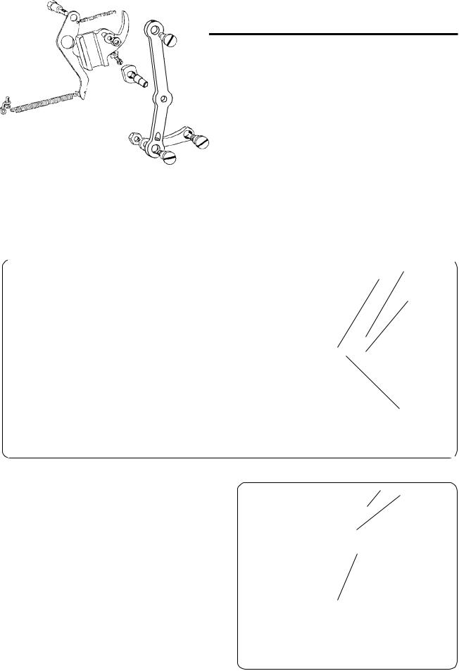
3. ADJUSTMENT OF THE STITCHES DENSITY IN CROSS BAR
(modification S 100 - 060)
1.Lift the machine head.
2. |
Loosen the nut . Move rod stud |
|
with lever in ring to centre of |
|
ring or from centre of the ring. |
|
By moving the lever to the centre the |
|
stitches density is decreased, |
|
by moving the lever form the centre |
|
the stitches density is increased. |
3. |
Tighten the nut . |
Revised 10/2005 1-22 e-mail: service@amfreece.cz ; parts@amfreece.cz; website: www.amfreece.com Phones: +420 582 309 146 (Service), +420 582 309 286 (Spare Parts); Fax: +420 582 360 606

S100
D - MACHINE ADJUSTMENT
4 . L E N G T H S O F T H E S E W I N G
The mechanism is not used for machine S 100 - 052 and S 100 - 053.
1. |
Loosen the clamp screw and move with the rod till , so that the needed sewing length on the |
|
dial rod is covered with the indicator mark . |
2. |
Tighten the screw . |
The total length of the sewing L was just adjusted - see picture.
N o t e : The total sewing length is the sum of the: length of cutting plus the length of the bar. If the fly bar sewing is needed, it is necessary to change the length of the shape cam.
WA R N I N G ! When the length of buttonhole is changed, it is necessary to change also the cutting steel with appropriate length.
Revised 10/2005
e-mail: service@amfreece.cz ; parts@amfreece.cz ; website: www.amfreece.com 1-23 Phones: +420 582 309 146 (Service), +420 582 309 286 (Spare Parts); Fax: +420 582 360 606
Loading...