


 Loading...
MODEL S-101
EYELET BUTTONHOLE MACHINE
PARTS AND SERVICE MANUAL
PART NUMBER 97. 1000.0.003
AMF is trademark of AMF Group, |
09/2004 |
Inc. |
|
2-14

MODEL S-101
EYELET BUTTONHOLE MACHINE
PARTS AND SERVICE MANUAL
PART NUMBER 97. 1000.0.003
AMF is trademark of AMF Group, |
09/2004 |
Inc. |
|
2-13

S-101
S-101
S-101
S-101
S-101
S-101
EYELET BUTTONHOLE MACHINE PARTS AND SERVICE MANUAL
EYELET BUTTONHOLE MACHINE PARTS AND SERVICE MANUAL
EYELET BUTTONHOLE MACHINE PARTS AND SERVICE MANUAL
EYELET BUTTONHOLE MACHINE PARTS AND SERVICE MANUAL
EYELET BUTTONHOLE MACHINE PARTS AND SERVICE MANUAL
EYELET BUTTONHOLE MACHINE PARTS AND SERVICE MANUAL
2-13

Warranty Registration Card
(Please Fax or Mail immediately after installation)
Note: All Warranty Claims Void, unless Registration Card on file at AMF Reece HQ
Machine model number:
(S101, S100, S104, S211, Decostitch, S4000 BH, etc)
Manufacturer‘s serial or production number:
Installation Site Information:
Customer‘s Name:
Customer‘s Mailing Address:
Customer‘s Telephone Number:
Supervising Mechanic‘s or Technician‘s Name:
Signature of Supervising Technician:
AMF Reece Technician‘s Name:
AMF Reece Technician‘s Signature:
Type of garment produced at this location?
Average Daily Production Expected from this machine?
(number of buttonholes, jackets sewn, pants produced, buttons sewn, etc)
Any special requirements required at this location?
What other AMF Reece Machines are at this location?
How can we serve you better?
Tovární 582, 796 25 Prostìjov, Czech Republic
Fax: +420 582 360 606, e-mail: service@amfreece.cz, website: www.amfreece.com

LIMITED WARRANTY ON NEW AMF REECE EQUIPMENT
Warranty provisions:
A ninety (90) day limited service labor warranty to correct defects in installation, workmanship, or material without charge for labor. This portion of the warranty applies to machines sold as ”installed” only .
A one (1) year limited material warranty on major component parts to replace materials with defects. Any new part believed defective must be returned freight prepaid to AMF Reece, Inc. for inspection. If, upon inspection, the part or material is determined to be defective, AMF Reece, Inc. will replace it without charge to the customer for parts or material.
Service labor warranty period shall begin on the completed installation date. Material warranty shall begin on the date the equipment is shipped from AMF Reece, Inc.
Exclusions:
Excluded from both service labor warranty and material warranty are: (1) Consumable parts which would be normally considered replaceable in day-to-day operations. These include parts such as needles, knives, loopers and spreaders. (2) Normal adjustment and routine maintenance. This is the sole responsibility of the customer. (3) Cleaning and lubrication of equipment. (4) Parts found to be altered, broken or damaged due to neglect or improper installation or application. (5) Damage caused by the use of non-Genuine AMF Reece parts. (6) Shipping or delivery charges.
There is no service labor warranty for machines sold as ”uninstalled”.
Equipment installed without the assistance of a certified technician (either an AMF Reece Employee, a Certified Contractor, or that of an Authorized Distributor) will have the limited material warranty only. Only the defective material will be covered. Any charges associated with the use of an AMF Reece Technician or that of a Distributor to replace the defective part will be the customer’s responsibility.
NO OTHER WARRANTY, EXPRESS OR IMPLIED,AS TO DESCRIPTION, QUALITY, MERCHANTABILITY, and FITNESS FOR APARTICULAR PURPOSE, ORANYOTHER MATTER IS GIVEN BYSELLER OR SELLER’S AGENT IN CONNECTION HEREWITH. UNDER NO CIRCUMSTANCES SHALL SELLER OR SELLER’S AGENT BE LIABLE FOR LOSS OF PROFITS ORANY OTHER DIRECT OR INDIRECT COSTS, EXPENSES, LOSSES OR DAMAGESARISING OUT OF DEFECTS IN OR FAILURE OF THE EQUIPMENT ORANY PART THEREOF.
WHATTO DO IFTHERE ISAQUESTION REGARDINGWARRANTY
If a machine is purchased through an authorized AMF Reece, Inc. distributor, warranty questions should be first directed to that distributor. However, the satisfaction and goodwill of our customers are of primary concern to AMF Reece, Inc. In the event that a warranty matter is not handled to your satisfaction, please contact the appropriate AMF Reece office:
Europe/Africa/Americas |
Southwest Asia |
||
Prostejov, Czech Republic |
Istanbul, Turkey |
||
Phone: |
(+420) 582-309-275 |
Phone: |
(+90) 212-465-0707 |
Fax: |
(+420) 582-360-608 |
Fax: |
(+90) 212-465-0711 |
e-mail: |
service@amfreece.cz |
e-mail: |
amfreeceturkey@superonline.com |
Southeast Asia
Kowloon, Hong Kong Phone: (+852) 2787-2273
Fax: (+852) 2787-5642
e-mail: amfreece@netvigator.com

S-101
1-8 |
Revised 09/2004 |
e-mail: service@amfreece.cz; parts@amfreece.cz; website: www.amfreece.com |
Phones: +420 582 309 146 (Service), +420 582 309 286 (Spare Parts); Fax: +420 582 360 606
S-101
CONTENTS
|
SHEET NO. |
INSTRUCTION FOR INSTALLATION ON REECE INDIVIDUAL TABLES ............ |
1-1 |
STOP MOTION ADJUSTMENTS ................................................................................... |
1-2 |
MODEL 101 - SETTING UP INSTRUCTIONS .............................................................. |
1-3 |
THREADING DIAGRAMS .............................................................................................. |
1-4 |
MODEL 101 - OPERATING INSTRUCTIONS ............................................................... |
1-7 |
ADJUSTMENTS THAT DETERMINE THE CHARACTER OF THE BUTTONHOLE |
|
Needle information ............................................................................................... |
1-8 |
Adjusting the bite and cutting space .................................................................... |
1-9 |
To adjuste the clamp spread ................................................................................. |
1-9 |
Adjusting the number of stitches per inch in a buttonhole ................................ |
1-10 |
Increasing or decreasing of number of stitches in the eye independently |
|
of the sides ............................................................................................................. |
1-10 |
Tension ................................................................................................................... |
1-10 |
MACHINE ADJUSTMENTS - CORRECTIVE AND MAINTENANCE |
|
Needle bar and race line up adjustment ............................................................... |
1-11 |
Equalizing the loopers .......................................................................................... |
1-12 |
Looper and spreader adjustment .......................................................................... |
1-13 |
To adjust play in split collar yoke ........................................................................ |
1-14 |
To line up and adjust the cutting lever................................................................. |
1-14 |
Adjusting the clamp operating mechanism ......................................................... |
1-15 |
To adjust the trip lever .......................................................................................... |
1-16 |
To correct distortion of eye................................................................................... |
1-16 |
To adjust the roll pressure on length gauge ......................................................... |
1-16 |
To adjust the rocker arm and stop motion ........................................................... |
1-17 |
Adjusting the stop latch on stitching wheel ........................................................ |
1-18 |
Adjusting the trigger setting mechanism ............................................................. |
1-18 |
To adjust the timing of the L.H. handwheel in relation to rocker shaft and |
|
lever ........................................................................................................................ |
1-18 |
To adjust L.H. handwheel to disengage at the stopping position |
|
of the machine ....................................................................................................... |
1-19 |
To adjust for friction on worm shaft .................................................................... |
1-19 |
To adjust for friction on main shaft ..................................................................... |
1-19 |
Revised |
09/2004 |
1-9 |
e-mail: service@amfreece.cz; parts@amfreece.cz; website: www.amfreece.com |
||
Phones: |
+420 582 309 146 (Service), +420 582 309 286 (Spare Parts); Fax: +420 582 360 606 |
|

S-101
CONTENTS
CUT BEFORE - MACHINE ADJUSTMENTS ............................................................... |
1-20 |
CORD TRIM |
|
Threading diamgrams ........................................................................................... |
1-23 |
Upper thread draw-off and tension adjustments ................................................. |
1-24 |
Thread pick-up adjustments ................................................................................. |
1-24 |
Under thread draw-off and tension release .......................................................... |
1-24 |
Thread trimmer and thread retainer ..................................................................... |
1-25 |
To set the under thread quide ............................................................................... |
1-26 |
Shear adjustment ................................................................................................... |
1-26 |
To adjust the hold down finger ............................................................................. |
1-26 |
ADJUSTMENT FOR THE ADJUSTABLE FLY BAR MACHINE ............................... |
1-27 |
CUT BEFORE ENDGING MACHINE ............................................................................ |
1-29 |
NEEDLES ........................................................................................................................... |
1-30 |
1-10 |
Revised 09/2004 |
e-mail: service@amfreece.cz; parts@amfreece.cz; website: www.amfreece.com |
Phones: +420 582 309 146 (Service), +420 582 309 286 (Spare Parts); Fax: +420 582 360 606

S-101
EQUIMENT FAMILIARIZATION
Description |
|
|
|
|
|
|
|
Eyelet Buttonhole Sewing Machine |
||||
Sewing Speed |
|
|
|
|
|
|
|
Up to 1,600 spm |
||||
|
|
|
|
|
|
|
|
|
|
|
|
|
Stitch Type |
|
|
|
|
|
|
|
401 two thread chainstitch |
||||
|
|
|
|
|
|
|
|
|
|
|
|
|
Stitch Density |
|
|
|
|
|
|
|
3 to 16 s/cm (7 to 40 spi) |
||||
|
|
|
|
|
|
|
|
|
|
|
|
|
Buttonhole Lenght |
|
|
|
|
|
|
|
13 to 32 mm ( 1/2" to 1 1/4") |
||||
Automatic Cutting Lenght |
|
|
|
|
|
|
|
N/A |
|
|||
|
|
|
|
|
|
|
|
|
|
|
|
|
Eze Shape (X; Y) mm |
|
|
|
|
|
|
|
No Eye; 2,7 x 4,3 |
||||
|
|
|
|
|
|
|
|
|
|
|
|
|
|
|
|
|
|
|
|
|
|
|
|
|
|
|
|
|
|
|
|
|
|
|
|
|
|
|
X |
|
|
|
|
Y |
|
|
|
|
|
||
|
|
|
|
|
|
|
|
|
|
|||
|
|
|
|
|
|
|
|
|
|
|
|
|
|
|
|
|
|
|
|
|
|
||||
|
|
|
|
|
|
|
|
|
||||
|
|
|
|
|
|
|
|
|
|
|
|
|
End Shape |
|
|
|
|
|
|
|
flibar, open end |
||||
|
|
|
|
|
|
|
|
|
|
|
|
|
Stitch Bite |
|
|
|
|
|
|
|
2 to 4 mm |
||||
|
|
|
|
|
|
|
|
|
|
|
|
|
Automatic Thread Triming |
|
|
|
|
|
|
|
AF - top thread only |
||||
|
|
|
|
|
|
|
|
|
|
|
|
|
Lubrication |
|
|
|
|
|
|
|
Semi - automatic wicking system |
||||
|
|
|
|
|
|
|
|
|
|
|
|
|
Electrical Supply |
|
|
|
|
|
|
|
230V, 50/60Hz, 3 Ph |
||||
|
|
|
|
|
|
|
|
|
|
|
400V, 50/60Hz, 3Ph |
|
|
|
|
|
|
|
|
|
|
|
|
230V, 50/60Hz, 1Ph |
|
|
|
|
|
|
|
|
|
|
|
|
110V 60Hz 1Ph |
|
|
|
|
|
|
|
|
|
|
|
|
|
|
Dimensions (crated) |
|
|
|
|
|
|
|
|
|
|||
Sewing Head |
|
|
|
|
|
|
|
|
|
|||
Lenght |
|
|
|
|
|
|
|
70 cm |
(27" 1/2") |
|||
Width |
|
|
|
|
|
|
|
55 cm |
(21" 1/2") |
|||
Height |
|
|
|
|
|
|
|
75 cm |
(29 1/2") |
|||
Weight |
|
|
|
|
|
|
|
74 kg (163 lbs) |
||||
|
|
|
|
|
|
|
|
|
|
|
|
|
Table |
|
|
|
|
|
|
|
|
|
|||
Lenght |
|
|
|
|
|
|
|
114 cm |
(45") |
|||
Width |
|
|
|
|
|
|
|
68 cm |
(27") |
|||
Height |
|
|
|
|
|
|
|
40 cm |
(16") |
|||
Weight |
|
|
|
|
|
|
|
80 kg |
(176 lbs) |
|||
|
|
|
|
|
|
|
|
|
|
|
|
|
Overall Dimensions |
|
|
|
|
|
|
|
|
|
|||
Floor Plan |
|
|
|
|
|
|
|
110 x 60 cm (43" x 24") |
||||
Table Height |
|
|
|
|
|
|
|
70 cm (27 1/2") adjustable to 90 cm (35") |
||||
Revised |
09/2004 |
|
e-mail: service@amfreece.cz; parts@amfreece.cz ; website: www.amfreece.com |
1-1 |
|
Phones: |
+420 582 309 146 (Service), +420 582 309 286 (Spare Parts); Fax: +420 582 360 606 |
|

S-101
INSTRUCTIONS FOR INSTALLATION ON REECE INDIVIDUAL TABLES
Parts and Belting for this installation are contained in the accessory box which accompanies each machine.
1. Be certain that Motor Pulley rotates in direction of arrow. If not, motor rotation must be corrected before operating machine.
2. Check with a plumb line to see that the heel of Transmitter Pedal is 6“ in back of front edge of the table.
3. Place the Machine on the Table between the belt slots and even with front edge of Table. Install crossed Belt o and open Belt p. The rear leg of Belt p must pass between the Idle Pulley q and Belt Guard r.
4. Adjust Machine sideways as necessary so that Belt p is central in its belt slot, and attach Machine to Table with 4 wood screws.
q5. Crank the Machine head to the rearmost point of its travel and adjust Idle Pulley q, to provide approximately 1/4“ clearance between Belt Guard r and the front leg of Belt p.
o r  n
n
p
6“
Approx 1/4“
p r q
1-2 |
Revised 09/2004 |
e-mail: service@amfreece.cz; parts@amfreece.cz; website: www.amfreece.com |
Phones: +420 582 309 146+ (Service), +420 582 309 286 (Spare Parts); Fax: +420 582 360 606

S-101
STOP MOTION ADJUSTMENTS
101 Stop Position - all 101 models except the Eyelet and Cross Oval - when the head of the machine is all the way forward.
1) Page 16, Figure 5 and 6 - Machine in stop position and the stitch wheel locked up. Check Roll 10.1122.0.000 ‘ on the 10.1120.0.000 Link. It should rest lightly on the 10.2018.1.000 ’ Length Gauge.
Adjust by turning Adjustment Screw 10.2066.0.000 u on Bracket 10.1127.3.000.
2) Page 17, Figure 1A - Machine in stop position - locked up. Roll 01.7002 p should lightly contact the low point of the cam on the inside of the Hand Wheel 10.1088.0.050. Adjust by loosening screw 10.1114.0.000 r on Three Forked Lever 10.1113.0.000 s. Recheck adjustment number 1.
3) Page 18, Figures 4 and 5 - While holding turning pressure on |
The full thickness .060“ (1/16“) is used to measure |
|
the clearance between the end of the Flyover Lever |
||
the Hand Wheel, |
||
and the Rocking Lever Dog when the roll reaches |
||
10.1088.0.050, crank the machine back by using the Cutting Wheel |
||
the highest point on the Length Gage. |
||
10.3039.0.000 instead of the Crank 10.3037.1. (On Cut Before |
||
|
||
machines, use the crank until after cutting or remove cutting steel.) |
|
|
The 10.1089.0.000 Dog v on the 10.1088.0.000 Hand Wheel |
|
|
should disengage the 10.1099.0.000 Bolt on the Rocking Lever |
|
|
as the 10.3038.1 Striker on the crank disengages the 10.3042.2 |
|
|
Dog on the cutting wheel. Adjust by loosening Clamp Screw |
|
|
01.2035.0.000 on Shifter Spool 10.3045.0.000 and moving in or |
|
|
out to suit. |
|
|
4) Page 17, Figure 3-A - Crank the machine back until the |
|
|
10.1122.0.000 Roll t is on the high point of the 10.2018 Length |
|
|
Gauge u. In this position, the 10.1085.0.000 Lever should be |
|
|
approximately 1/16“ from the 10.1102.0.000 Dog (not shown). |
|
|
Adjust by loosening nut 10.3005 and positioning. Set the rise and |
|
|
fall of the 10.1085 Lever so that its lowest point is approximately |
|
|
1/16“ below the top of the 10.1102.0.000 Dog. Adjust by |
|
|
positioning 10.1087.0.000 Bracket. |
|
|
Check 10.1124.0.000 Lever w for correct clearance of Dog on the |
0.20“ Step at one end measures space between end of |
|
Three Forked Lever (10.1113.0.000) - s by lifting 10.1118.0.000 |
||
Flyover Lever and Rocking Lever Dog when Three |
||
Lever, which releases the 10.1120.0.000 Roll t and lets the |
||
Forked Lever is held by Trip Lever and Flyover Lever |
||
10.1124.0.000 w take over. The 10.1102.1.000 should not move |
||
is at its lowest point. |
||
more than 2/3 of the distance to 10.1085.0.000. Adjust |
||
The Depth of the Step, .062“ measures the distance |
||
10.1124.0.000 to suit. |
||
that the lower tip of the Flyover Lever should be below |
||
|
||
5 & 6) Page 19, Figure 1. |
the top of the Rocking Lever Dog under the same |
|
circumstances. |
||
|
5)Stop position 1/64“ between points (r and s).
6)Crank machine through cycle until 10.3039.0.000 Cutting Wheel (Fig.1) shifts part way out as Lever w (10.1124.0.000, Fig. 3-A, Page 17) is released. When one stitch more is taken by turning the hand wheel, the cutting wheel shifts all the way out and the hand wheel is locked up. Contact points at (r and s) should just clear when the cutting wheel moves out. If hitting, adjust wheel inward
by loosening screw  . Figure 5, Page 18 and tapping wheel. Recheck adjustment 3. If compensation between these two adjustments is not possible, the lower prong of the Three Forked
Lever has to be bent (removed from machine). |
Corner Step, 1/32“ measures distance between Dogs |
|
|
||
|
on Cutting Wheel and Crank when machine is in |
|
Revised 09/2004 |
home locked position. |
|
|
|
|
e-mail: service@amfreece.cz; parts@amfreece.cz ; website: www.amfreece.com |
1-3 |
|
Phones: +420 582 309 146 (Service), +420 582 309 286 (Spare Parts); Fax: +420 582 360 606 |
||

S-101
MODEL 101 - SETTING UP INSTRUCTIONS
Before operating the machine by hand or power, remove the two shipping pins nshown Fig.1, which are easily identified by a red tag tied to each - these pins nare installed at the factory to lock the Head oand Bed Plate ptogether as a protection against shipping damages.
Set up machine in accordance with the instructions on the installation template that is sent with each new machine. This template shows two different installations depending on direction of rotation of the power shaft. The one marked „Preferred Installation“ on which the left hand machine belt is crossed and the
right hand one open, should always be employed when the machine is installed on a Reece Individual Motorized Table. The „Preferred Installation“ should also be used whenever possible in cases where the machine is installed on a line shaft table.
In the event that the machine should be disassembled at any time, the correct line-up of the Head o on the Bed Plate p can be re-established by using one of the shipping pins n in the follower manner:
Turn the left hand crank handle until shipping pin hole q Fig. 2 in the Head o corresponds with shipping pin hole r in Bed Plate p. If holes q and r do not line up exactly, loosen clamp screw u Fig. 2 and move the Head o of machine to left or right until holes q and r line up when tested with the shipping pin. If no shipping pin is available, proceed as outlined above, but match line s on Head o with line t on Bed Plate p as illustrated Fig. 2. Important - Before tightening clamp screw u, press lever 1-C19 v upward on the stud to lightly contact the shoulder of the Cam Case w. Note - Do not follow these line-up instructions on Adjustable Fly Bar machines. Use the instructions on Sheet 28.
1-4 |
Revised 09/2004 |
e-mail: service@amfreece.cz; parts@amfreece.cz; website: www.amfreece.com |
Phones: +420 582 309 146+ (Service), +420 582 309 286 (Spare Parts); Fax: +420 582 360 606
S-101
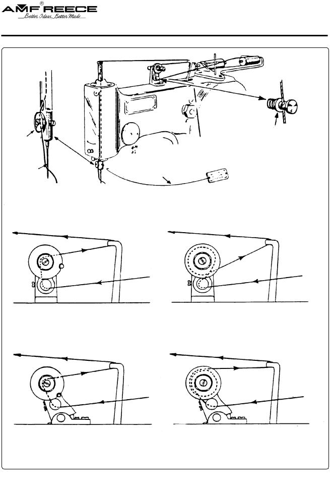
THREADING DIAGRAMS
UPPER SYSTEM
Thread is |
Detail |
between |
|
tension discs |
|
Long groove |
|
Use T-20 thrading wire for threading needle bar
Detail
Spread washer so that thread will rest in notch
THREADING OF FIXED TYPE TENSIONS |
|
|
S p l i t d i s c t y p e |
S o l i d r o l l e r t y p e |
|
To needle bar |
To needle bar |
|
From thread |
From thread |
|
supply |
||
supply |
||
|
||
|
N o t e : Thread makes approximately one full turn |
|
|
around the roller on this tension. |
|
THREADING OF ROCKING TYPE TENSIONS |
||
S p l i t d i s c t y p e |
S o l i d r o l l e r t y p e |
|
To needle bar |
To needle bar |
|
From thread |
From thread |
|
supply |
supply |
|
N o t e : Thread makes approximately 1 1/2 turns around the roller on this tension.
N o t e : Refer to sheet 23 for additional information on threading Cord Trim Machines.
Revised |
09/2004 |
|
e-mail: service@amfreece.cz; parts@amfreece.cz ; website: www.amfreece.com |
1-5 |
|
Phones: |
+420 582 309 146 (Service), +420 582 309 286 (Spare Parts); Fax: +420 582 360 606 |
|

S-101
THREADING DIAGRAMS
LOWER SYSTEM
Turn L.H. handwheel until race and loopers are in front. Thread as shown.
Threading details for split disc tension
CORD THREADING DIAGRAM
Threading details for solid roller tension
Throat plate |
Race |
Crank machine until race faces as shown.
Note:
Cord may also be led from rear of machine through guide A, and up through the race and throat plate as shown.
Note: Refer to Sheet 23 for threading diagrams on Cord Trim Machines.
1-6 |
Revised 09/2004 |
e-mail: service@amfreece.cz; parts@amfreece.cz; website: www.amfreece.com |
Phones: +420 582 309 146+ (Service), +420 582 309 286 (Spare Parts); Fax: +420 582 360 606
Loading...