

Page 1

DCS-E 1kW Series,
DLM-E 3kW & 4kW
Power Supplies
M51A Option: Isolated Analog
Programming Manual
M362250-01 Rev C www.programmablepower.com
Page 2

Page 3

Page 4

Page 5

About AMETEK
AMETEK Programmable Power, Inc., a Division of AMETEK, Inc., is a global leader in the design
and manufacture of precision, programmable power supplies for R&D, test and measurement,
process control, power bus simulation and power conditioning applications across diverse
industrial segments. From bench top supplies to rack-mounted industrial power subsystems,
AMETEK Programmable Power is the proud manufacturer of Elgar, Sorensen, California
Instruments and Power Ten brand power supplies.
AMETEK, Inc. is a leading global manufacturer of electronic instruments and electromec hanical
devices with annualized sales of $2.5 billion. The Company has over 11,000 colleagues working
at more than 80 manufacturing facilities and more than 80 sales and service centers in the United
States and around the world.
Trademarks
AMETEK is a registered trademark of AMETEK, Inc. Sorensen is a trademark of AMETEK , Inc.
Other trademarks, registered trademarks, and product names are the property of their respective
owners and are used herein for identification purposes only.
Notice of Copyright
DCS-E 1kW Series, DLM-E 3kW & 4kW Power Supplies M51A Option: Isolated Analog
Programming Manual
© 2004 AMETEK Programmable Power, Inc. All rights reserved.
Exclusion for Documentation
UNLESS SPECIFICALLY AGREED TO IN WRITING, AMETEK PROGRAMMABLE POWER, INC.
(“AMETEK”):
(a) MAKES NO WARRANTY AS TO THE ACCURACY, SUFFICIENCY OR SUITABILITY OF ANY
TECHNICAL OR OTHER INFORMATION PROVIDED IN ITS MANUALS OR OTHER
DOCUMENTATION.
(b) ASSUMES NO RESPONSIBILITY OR LIABILITY FOR LOSSES, DAMAGES, COSTS OR
EXPENSES, WHETHER SPECIAL, DIRECT, INDIRECT, CONSEQUENTIAL OR INCIDENTAL,
WHICH MIGHT ARISE OUT OF THE USE OF SUCH INFORMATION. THE USE OF ANY SUCH
INFORMATION WILL BE ENTIRELY AT THE USER’S RISK, AND
(c) REMINDS YOU THAT IF THIS MANUAL IS IN ANY LANGUAGE OTHER THAN ENGLISH,
ALTHOUGH STEPS HAVE BEEN TAKEN TO MAINTAIN THE ACCURACY OF TH E
TRANSLATION, THE ACCURACY CANNOT BE GUARANTEED. APPROVED AMETEK CONTENT
IS CONTAINED WITH THE ENGLISH LANGUAGE VERSION, WHICH IS POSTED AT
WWW.PROGRAMMABLEPOWER.COM.
Date and Revision
November 2008 Revision C
Part Number
M362250-01
Contact Information
Telephone: 800 733 5427 (toll free in North America)
858 450 0085 (direct)
Fax: 858 458 0267
Email: sales@programmablepower.com
service@programmablepower.com
Web: www.programmablepower.com
i
Page 6

This page intentionally left blank.
ii
Page 7
G
G
Important Safety Instructions
Before applying power to the system, verify that your product is configured properly for your
particular application.
WARNIN
WARNIN
Only qualified personnel who deal with attendant hazards in power supplies, are allowed to perform
installation and servicing.
Ensure that the AC power line ground is connected properly to the Power Rack input connector or
chassis. Similarly, other power ground lines including those to application and maintenance
equipment must be grounded properly for both personnel and equipment safety.
Always ensure that facility AC input power is de-energized prior to connecting or disconnecting any
cable.
In normal operation, the operator does not have access to hazardous voltages within the chassis.
However, depending on the user’s application configuration, HIGH VOLTAGES HAZARDOUS TO
HUMAN SAFETY may be normally generated on the output terminals. The customer/user must
ensure that the output power lines are labeled properly as to the safety hazards and that any
inadvertent contact with hazardous voltages is eliminated.
Guard against risks of electrical shock during open cover checks by not touching any portion of the
electrical circuits. Even when power is off, capacitors may retain an electrical charge. Use safety
glasses during open cover checks to avoid personal injury by any sudden component failure.
Neither AMETEK Programmable Power Inc., San Diego, California, USA, nor any of the subsidiary
sales organizations can accept any responsibility for personnel, material or inconsequential injury,
loss or damage that results from improper use of the equipment and accessories.
Hazardous voltages may be present when covers are removed. Qualified
personnel must use extreme caution when servicing this equipment.
Circuit boards, test points, and output voltages also may be floating above
(below) chassis ground.
The equipment used contains ESD sensitive parts. When installing
equipment, follow ESD Safety Procedures. Electrostatic discharges might
cause damage to the equipment.
SAFETY SYMBOLS
iii
Page 8

This page intentionally left blank.
iv
Page 9

CONTENTS
SECTION 1 M51A OPTION OVERVIEW .............................................1-1
1.1 Introduction ...................................................................................................... 1-1
1.2 General Description ......................................................................................... 1-1
1.3 Specifications................................................................................................... 1-2
1.3.1 Electrical Specifications ....................................................................... 1-2
1.3.2 Supplemental Characteristics .............................................................. 1-2
SECTION 2 ISOLATED ANALOG PROGRAMMER OPERATION .........2-1
2.1 SW1 Switch ..................................................................................................... 2-1
2.1.1 SW1 Switch Setup ............................................................................... 2-2
2.2 ISOLATED ANALOG PROGRAMMER Connector (J4)................................... 2-3
2.2.1 ISOLATED ANALOG PROGRAMMER Functions ............................... 2-4
2.3 Remote Programming Configuration ............................................................... 2-7
2.3.1 Voltage Source Programming of Output Voltage................................. 2-7
2.3.2 Voltage Source Programming of Output Current................................. 2-8
2.3.3 Voltage Source Programming of OVP ................................................. 2-9
2.3.4 Resistance Programming of Output Voltage ..................................... 2-10
2.3.5 Resistance Programming of Output Current...................................... 2-11
2.3.6 Resistance Programming of OVP...................................................... 2-12
2.3.7 4-20mA Current Source Programming of Output Voltage ................. 2-13
2.3.8 4-20mA Current Source Programming of Output Current.................. 2-14
2.3.9 Programming the Shutdown Function ............................................... 2-15
2.3.10 TTL Shutdown ................................................................................. 2-15
2.3.11 Shutdown Application – Contact Closure ........................................ 2-16
2.3.12 Local/Remote Application ................................................................ 2-18
2.4 Remote Monitoring ........................................................................................ 2-19
2.5 Remote Digital Status Signals ....................................................................... 2-19
M51A Option v
Page 10

Contents DLM-E Series and DCS-E Series
LIST OF TABLES
Table 2–1. SW1 SETUP Switch.................................................................................. 2-1
Table 2–2. ISOLATED ANALOG PROGRAMMER Connector Pinout ........................ 2-3
Table 2–3. Remote Monitoring................................................................................. 2-19
Table 2–4. Remote Digital Status Signals ............................................................... 2-19
LIST OF FIGURES
Figure 2–1. Rear Panel View, DLM-E Series 3kW and 4kW Power Supply ............... 2-2
Figure 2–2. Rear Panel View, DCS-E Series 1kW Power Supply .............................. 2-2
Figure 2–3. Using Shutdown with a DC Input (Positive Logic) ................................. 2-15
Figure 2–4. Using Shutdown with Contact Closure of a Normally OPEN Relay
(SW1-6 ON)........................................................................................... 2-16
Figure 2–5. Using Shutdown with Contact Closure of a Normally OPEN Relay
(SW1-6 OFF) ......................................................................................... 2-17
Figure 2–6. Using Shutdown with Contact Closure of a Normally CLOSED Relay
(SW1-6 ON)........................................................................................... 2-17
Figure 2–7 Using Local/Remote Operation with Contact Closure ............................ 2-18
vi M51A Option
Page 11

SECTION 1
M51A OPTION OVERVIEW
1.1 Introduction
This manual is to be used in conjunction with the DCS-E 1kW Series & DCS-E 1.2kW Series
DC Power Supplies Operation Manual, Sorensen Document No. M362500-01 and the DLM-E
3Kw & 4Kw Series Power Supplies Operation Manual, Sorensen Document No. M362000-01.
The Sorensen M51A Option provides a remote isolated analog programming interface, which
has safety isolation from the output terminals. This allows the remote analog interface to be
connected to user–accessible, Safety Extra Low Voltage, (SELV) control circuits, even though
the output terminals are floated at a high potential with respect to the chassis.
1.2 General Description
The M51A Option provides isolation for all programming, monitoring, and digital I/O signals that
are available through the standard rear panel analog interface connector. This isolation barrier
eliminates the connection that exists in the standard models between the non-isolated remote
interface circuits and the power supplies output return (negative) terminal. All control and
monitoring signals on the M51A option are optically coupled from the power supply output, and
can are user accessible irrespective of the float potentials that could exist at the output
terminals.
The M51A Option provides a full complement of programming, monitoring, and control
functions. Remote programming is available for output voltage, current, and overvoltage
protection (OVP). Analog output monitor signals are available for the output voltage and
current. Digital I/O signals provide indication of the operational state, and a means of enabling
the remote interface and the output.
The type and range of the control and monitor signals are user-selectable with a rear panel
setup switch and connector jumpers. The output voltage, current, and OVP can be programmed
with a 0-5VDC, 0-10VDC, or 0-5kΩ resistance; in addition, the output voltage and current can
be programmed with 4-20mA signals. The output voltage and current monitors can produce
0-5VDC, 0-10VDC, or 4-20mA signals. Isolated 1mA current sources are provided to facilitate
the utilization of 0-5kΩ programming resistances.
Except for the isolated remote analog interface, the installation and operation of the power
supplies remains as presented in the Operation Manual. The following sections provide a
detailed description of the new features and the differences in operation.
M51A Option 1-1
Page 12

M51A Option Overview DLM-E Series and DCS-E Series
1.3 Specifications
1.3.1 Electrical Specifications
Remote Voltage Programming Accuracy, 0-5/10V Inputs:
Output Voltage: 0.5% of Vmax
Output Current: 0.75% of Imax
OVP: 1.0% of 1.1 X Vmax
Remote 4-20 mA Programming Accuracy:
Output Voltage: 1.0% of Vmax
Output Current: 1.0% of Imax
Burden voltage of 6.25 VDC (312.5 ohms nominal)
1.3.2 Supplemental Characteristics
Remote Resistance Programming Accuracy, 0-5kΩ Input:
Output Voltage: 1.0% of Vmax
Output Current: 1.5% of Imax
OVP: 1.5% of 1.1 X Vmax
Remote Monitor Accuracy:
Output Voltage, 0-5/10V ranges: 0.5% of Vmax
Output Voltage, 4-20mA: 1.0% of Vmax
Output Current, 0-5/10V ranges: 0.75% of Imax
Output Current, 4-20mA: 1.0% of Imax
Electrical Isolation:
500 VDC from all isolated inputs to supply output
1-2 M51A Option
Page 13

SECTION 2
ISOLATED ANALOG
PROGRAMMER OPERATION
2.1 SW1 Switch
The SW1 SETUP switch is accessible from the rear panel of the unit. It provides user selection
of the programming/monitoring ranges and shutdown logic signal level. Setting a switch to the 1
or 0 position changes a range. The factory default settings are shown below.
Refer to Figure 2–1 for a rear panel view of the DLM-E 3kW and 4kW models.
Refer to Figure 2–2 for a rear panel view of the DCS-E 1kW models.
Switch
Position
1
2
3
4
5
6
* Indicates default settings
Output Voltage Monitor
Output Current Monitor
Remote ON-OFF Level
Function OFF (0) Position ON (1) Position
Voltage Programming
Range Select
Current Programming
Range Select
OVP Programming
Range Select
Range Select
Range Select
Select
0-10 VDC
0-10 VDC * 0-5 VDC, 4-20mA
0-10 VDC * 0-5 VDC
* 0-5 VDC 0-10 VDC
* 0-5 VDC 0-10 VDC
Active Low Signal * Active High Signal
* 0-5 VDC, 4-20mA
Table 2–1. SW1 SETUP Switch
M51A Option 2-1
Page 14

Isolated Analog Programmer Operation DLM-E Series and DCS-E Series
2.1.1 SW1 Switch Setup
The following sections describe the functions of the various switch positions:
Voltage Programming Range Select (V PROG): SW1-1, ON (1) position, selects 0-5VDC
programming range for the output voltage. Must also be set to ON (1) position when the Isolated
Analog Programmer is wired for 4-20mA input programming. OFF (0) position, selects 010VDC programming for the output voltage.
Current Programming Range Select (I PROG): SW1-2, ON (1) position selects 0-5VDC
programming range for the output current. Must also be set to ON (1) position when the Isolated
Analog Programmer is wired for 4-20mA input programming. OFF (0) position, selects 0-10VDC
programming for the output voltage.
OVP Programming Range Select (OVP PROG): SW1-3, ON (1) position selects 0-5VDC
programming of OVP threshold. OFF (0) position, selects 0-10VDC programming for OVP
threshold.
Output Voltage Monitor Range Select (V MON): SW1-4, ON (1) position selects 0-10VDC
range for readback of output voltage. OFF (0) position selects 0-5VDC readback of output
voltage. 4-20mA readback for output voltage is independent of the position of this switch.
Output Current Monitor Range Select (I MON): SW1-5, ON (1) position selects 0-10VDC
range for readback of output current. OFF (0) position selects 0-5VDC readback of output
current. 4-20mA readback for output current is independent of the position of this switch.
Remote ON-OFF Level Select (S/D): SW1-6, ON (1) position selects ACTIVE-HIGH logic level
for disabling the output with the S/D signal of the Isolated Analog Programmer connector. OFF
(0) position selects the ACTIVE-LOW logic level for disabling the output with the S/D signal of
the Isolated Analog connector.
Figure 2–1. Rear Panel View, DLM-E Series 3kW and 4kW Power Supply
Figure 2–2. Rear Panel View, DCS-E Series 1kW Power Supply
2-2 M51A Option
Page 15

DLM-E Series and DCS-E Series Isolated Analog Programmer Operation
2.2 ISOLATED ANALOG PROGRAMMER Connector (J4)
The ISOLATED ANALOG PROGRAMMER connector is a 25-position female
Subminiature-D type. The table below defines each pins function.
Pin Function
1 ANALOG-CONTROL input
2 Isolated Analog Common
3 OVP programming input
4 Voltage monitor output, 4-20mA
5 VOLTAGE-MODE status output
6 Isolated Analog Common
7 Current monitor output, 0-5/10V
8 4-20mA voltage programming offset signal (-2.5VDC)
9 Voltage programming input, 0-5/10V
10 Current programming input, 0-5/10V
11 4-20mA current programming offset signal (-2.5VDC)
12 Isolated Analog Common
13 Return for 4-20mA current programming signal
14 Shut-Down input
15 Auxiliary 16VDC output (+)
16 OVP resistance programming output, 1mA source
17 OVP status output
18 FAULT status output
19 Voltage monitor output, 0-5/10V
20 Input for 4-20mA current programming offset signal (-2.5VDC)
21 Voltage resistance programming output, 1mA source
22 Current resistance programming output, 1mA source
23 Input for 4-20mA current programming offset signal (-2.5VDC)
24 Current monitor output, 4-20mA
25 Return for 4-20mA voltage programming
Table 2–2. ISOLATED ANALOG PROGRAMMER Connector Pinout
CAUTION
The signals of the ISOLATED ANALOG PROGRAMMER have an
internal connection to chassis ground. Damage could result if the
voltage from signal returns, Pin-2, 6, 12, 13, and 25 to chassis ground
exceeds 60VDC.
M51A Option 2-3
Page 16

Isolated Analog Programmer Operation DLM-E Series and DCS-E Series
2.2.1 ISOLATED ANALOG PROGRAMMER Functions
The following sections describe the functions of the various signals of the ISOLATED ANALOG
Programmer. Circuit is SELV, and all connections have electrical isolation from the output of the
unit. Pin numbers correspond to the rear panel J4 connector pin out of Table 2–2.
Digital Control Input Signals
ANALOG-CONTROL (Remote/Local): Pin-1, enables remote analog programming with an
active-low logic level. When a low level is applied, the supply will power-up with the analog
interface in control of the output voltage. When high, the power supply will be in local control
mode. Signal return is at J4-2.
EXTERNAL SHUT DOWN (S/D): Pin-14, disables the output when applied and supply is
working in the Remote Control mode. Logic level can be selected with switch SW1-6 to be
active high or low. Signal return is at J4-2.
Digital Control Status Output Signals
VOLTAGE-MODE: Pin-5, nominal 5VDC logic level indicates operation in constant-voltage
mode. Low logic level indicates operation in constant current mode. Signal return is at J4-2.
OVP: Pin-17, nominal 5VDC logic level indicates that the output has been disabled because of
overvoltage protection. Signal return is at J4-2.
FAULT: Pin-18, nominal 5VDC logic level indicates that the output is disabled because of an
over temperature or shutdown fault. Signal return is at J4-2.
Analog Monitor Signals
VOLTAGE MONITOR, 0-5/10V: Pin-19, provides an analog readback of the output voltage
with a 0-5VDC or 0-10VDC signal (user selectable with switch SW1-4) indicating 0-100% of full
scale output. Signal is referenced to J4-6.
VOLTAGE MONITOR, 4-20mA: Pin-4, provides an analog readback of the output voltage with
a 4-20mA signal indicating 0-100% of full scale output. Signal return for the 4-20mA current is
J4-6.
CURRENT MONITOR, 0-5/10V: Pin-7, provides an analog readback of the output current with
a 0-5VDC or 0-10VDC signal (user selectable with switch SW1-5) indicating 0-100% of full scale
output. Signal return is at J4-6.
CURRENT MONITOR, 4-20mA: Pin-24, provides an analog readback of the output current
with a 4-20mA signal indicating 0-100% of full scale output. Signal return for the 4-20mA current
is J4-6.
2-4 M51A Option
Page 17

DLM-E Series and DCS-E Series Isolated Analog Programmer Operation
Analog Programming Signals
OVP PROGRAMMING INPUT: Pin-3, an input signal of 0-5 volts or 0-10 volts (user selectable
with switch SW1-3) programs the OVP threshold from 5-110% of full scale output voltage.
Signal return is at J4-12.
Note: The OVP input is programmed to 110% by an internal connection between the 1mA
source on Pin-16 to a separate circuit. This allows the user to program remotely without having
to provide a separate programming source or jumper to the OVP input.
VOLTAGE PROGRAMMING INPUT: Pin-9, an input signal of 0-5 volts, 0-10 volts or 4-20mA
programs the output voltage from 0-100% of full scale.
a) An input signal of 0-5 volts or 0-10 volts (user selectable with switch SW1-1) programs the
output voltage from 0-100% of full scale. Signal return is at J4-12.
b) An input signal of 4-20mA (with switch SW1-1 set to ON (1) position, programs the output
voltage from 0-100% of full scale. Jumpers from J4-25 to J4-12 and J4-20 to J4-8 are also
required. Signal return for the 4-20mA current is J4-25.
CURRENT PROGRAMMING INPUT: Pin-10, an input signal of 0-5 volts, 0-10 volts or 4-20mA
programs the output current from 0-100% of full scale.
a) An input signal of 0-5 volts or 0-10 volts (user selectable with switch SW1-2) programs the
output current from 0-100% of full scale. Signal return is at J4-12.
b) An input signal of 4-20mA (with switch SW1-2 set to ON (1) position) programs the output
current from 0-100% of full scale. Jumpers from J4-13 to J4-12 and J4-23 to J4-11 are also
required. Signal return for the 4-20mA current is J4-23.
OVP RESISTANCE PROGRAMMING OUTPUT: Pin-16, provides a 1mA current source which
when connected to Pin-3, the OVP PROG INPUT, with a 0-10KΩ external resistor connected
between Pin-16 and Pin-12, programs the OVP threshold from 5-110% of full scale output
voltage. Switch SW1-3 must be set to ON (1) to select 0-5VDC input range.
Note: The OVP input is programmed to 110% by an internal connection between the 1mA
source on Pin-16 to a separate circuit. This allows the user to program remotely without having
to provide a separate programming source or jumper to the OVP input.
VOLTAGE RESISTANCE PROGRAMMING OUTPUT: Pin-21, provides a 1mA current source
which when connected to Pin-9, the V PROG INPUT, with a 0-5KΩ external resistor connected
between Pin-21 and Pin-12, programs the output voltage from 0-100% of full scale output.
Switch SW1-1 must be set to ON (1) to select 0-5VDC input range.
CURRENT RESISTANCE PROGRAMMING OUTPUT: Pin-22, provides a 1mA current source
which when connected to Pin-10, the I PROG INPUT, with a 0-5KΩ external resistor connected
between Pin-22 and Pin-12, programs the output current from 0-100% of full scale output.
Switch SW1-2 must be set to ON (1) to select 0-5VDC input range.
M51A Option 2-5
Page 18

Isolated Analog Programmer Operation DLM-E Series and DCS-E Series
Auxiliary Sources
AUXILIARY DC OUTPUT: Pin-15, 16VDC source for use with logic and programming circuits.
Source capability is adequate to provide for full scale programming of output voltage, current, or
OVP when the user connects it to the appropriate programming input(s). Source is referenced
to Pin-6. Can be used as a source for 4-20mA programming current.
AUXILIARY DC RETURN: Pin-6, return for AUXILIARY source output.
4-20MA CURRENT PROGRAMMING OFFSET SIGNAL (-2.5VDC): Pin-8, provides a negative
2.5VDC to zero out the 4mA signal generated by internal circuits when using 4-20mA
programming of output voltage. Jumpers to Pin-20.
4-20MA CURRENT PROGRAMMING OFFSET SIGNAL (-2.5VDC): Pin-11, provides a
negative 2.5VDC to offset the signal generated by internal circuits when using 4-20mA
programming of output current. Jumpers to Pin-23.
2-6 M51A Option
Page 19

DLM-E Series and DCS-E Series Isolated Analog Programmer Operation
2.3 Remote Programming Configuration
2.3.1 Voltage Source Programming of Output Voltage
SW1 Switch Settings
SW1-1 ON (1)= 0–5V
SW1-1 OFF (0)= 0–10V
291213 1
25
14
Set up for voltage source programming of the output voltage as follows:
1. Set SW1-1, V PROG, to ON (1) for 0-5VDC programming range.
2. Set SW1-1, V PROG, to OFF (0) for 0-10VDC programming range.
3. Connect the external programming voltage source to the ISOLATED ANALOG
PROGRAMMER connector, J4, with positive to Pin-9 and negative to Pin-12.
4. Connect Pin-1, ANALOG-CONTROL, of the ISOLATED ANALOG PROGRAMMER
connector, J4, to Pin-2 to enable remote control.
5. Program the other parameters to the desired limit values.
M51A Option 2-7
Page 20

Isolated Analog Programmer Operation DLM-E Series and DCS-E Series
2.3.2 Voltage Source Programming of Output Current
SW1 Switch Settings
SW1-2 ON (1) = 0–5V
SW1-2 OFF (0)= 0–10V
2101213 1
25
14
Set up for voltage source programming of the output voltage as follows:
1. Set SW1-2, I PROG, to ON (1) for 0-5VDC programming range.
2. Set SW1-1, V PROG, to OFF (0) for 0-10VDC programming range.
3. Connect the external programming voltage source to the ISOLATED ANALOG
PROGRAMMER connector, J4, with positive to Pin-10 and negative to Pin-12.
4. Connect Pin-1, ANALOG-CONTROL, of the ISOLATED ANALOG PROGRAMMER
connector, J4, to Pin-2 to enable remote control.
5. Program the other parameters to the desired limit values.
2-8 M51A Option
Page 21
DLM-E Series and DCS-E Series Isolated Analog Programmer Operation
2.3.3 Voltage Source Programming of OVP
SW1 Switch Settings
SW1-3 ON (1) = 0–5V
SW1-3 OFF(0) = 0–10V
2361213 1
25
1416
Set up for voltage source programming of OVP as follows:
1. Set SW1-3, OVP PROG, to ON (1) for 0-5VDC programming range.
2. Set SW1-3, OVP PROG, to OFF (0) for 0-10VDC programming range.
3. Connect the external programming voltage source to the ISOLATED ANALOG
PROGRAMMER connector, J4, with positive to Pin-5 and negative to Pin-12.
4. Connect Pin-1, ANALOG-CONTROL, of the ISOLATED ANALOG PROGRAMMER
connector, J4, to Pin-2 to enable remote control.
5. Connect Pin 16, OVP RESISTANCE PROGRAMMING OUTPUT, of the ISOLATED
ANALOG PROGRAMMER connector, J4, to Pin 6 to disable the default OVP
programming connection.
6. Program the other parameters to the desired limit values.
M51A Option 2-9
Page 22

Isolated Analog Programmer Operation DLM-E Series and DCS-E Series
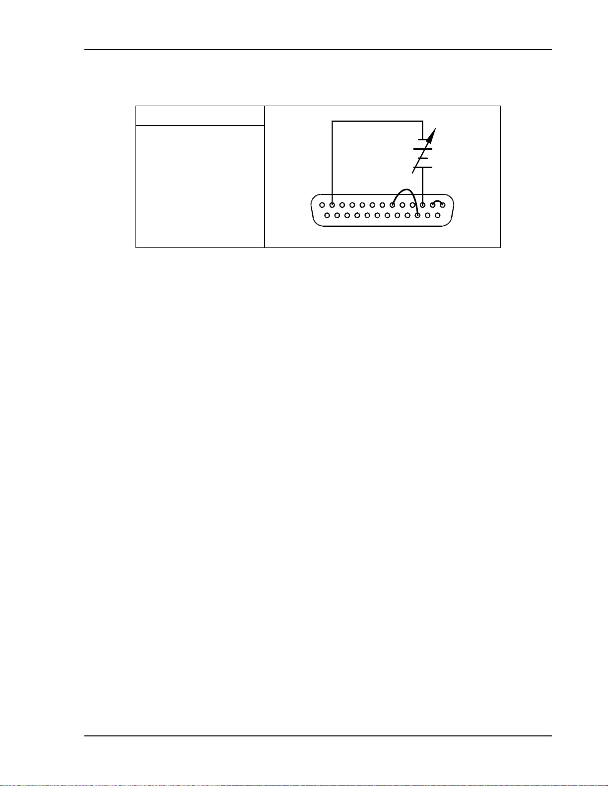
2.3.4 Resistance Programming of Output Voltage
SW1 Switch Settings
SW1-1 ON (1) = 0–5K
291213 1
25 21
14
Set up for resistance programming of the output voltage as follows:
1. Set SW1-1, V PROG, to ON (1) for 0-5VDC programming range.
2. Connect the external programming resistance, 0-5kΩ, to the ISOLATED ANALOG
PROGRAMMER connector, J4, from Pin-9 to Pin-12.
3. Connect a jumper from Pin-21 to Pin-9 to connect the 1mA current source.
4. Connect Pin-1, ANALOG-CONTROL, of the ISOLATED ANALOG PROGRAMMER
connector, J4, to Pin-2 to enable remote control.
5. Program the other parameters to the desired limit values.
2-10 M51A Option
Page 23

DLM-E Series and DCS-E Series Isolated Analog Programmer Operation
2.3.5 Resistance Programming of Output Current
SW1 Switch Settings
SW1-2 ON (1) = 0–5K
2101213 1
25 22
14
Set up for resistance programming of the output current as follows:
1. Set SW1-2, I PROG, to ON (1) for 0-5VDC programming range.
2. Connect the external programming resistance, 0-5kΩ, to the ISOLATED ANALOG
PROGRAMMER connector, J4, from Pin-10 to Pin-12.
3. Connect a jumper from Pin-22 to Pin-10 to connect the 1mA current source.
4. Connect Pin-1, ANALOG-CONTROL, of the ISOLATED ANALOG PROGRAMMER
connector, J4, to Pin-2 to enable remote control.
5. Program the other parameters to the desired limit values.
M51A Option 2-11
Page 24

Isolated Analog Programmer Operation DLM-E Series and DCS-E Series
2.3.6 Resistance Programming of OVP
SW1 Switch Settings
SW1-3 ON (1) = 0–5K
2361213 1
25
141621
Set up for resistance programming of the output voltage as follows:
1. Set SW1-3, OVP PROG, to ON (1) for 0-5VDC programming range.
2. Connect the external programming resistance, 0-5KΩ, to the ISOLATED ANALOG
PROGRAMMER connector, from Pin-3 to Pin-12.
3. Connect a jumper from Pin-3 to Pin-21 or Pin-22, (whichever one is available) to connect
the 1mA current source.
4. Connect Pin-1, ANALOG-CONTROL, of the ISOLATED ANALOG PROGRAMMER
connector, J4, to Pin-2 to enable remote control.
5. Program the other parameters to the desired limit values.
6. Connect Pin-16, OVP Default Programming Input, of the ISOLATED ANALOG
PROGRAMMER connector (J4) to Pin-6 to disable the default OVP programming
connection.
2-12 M51A Option
Page 25

DLM-E Series and DCS-E Series Isolated Analog Programmer Operation
5
2.3.7 4-20mA Current Source Programming of Output Voltage
SW1 Switch Settings
SW1-1 ON (1) = 4-20mA
4-20mA
8
91213 12
2
1420
Set up for 4-20 mA programming of the output voltage as follows:
1. Set SW1-1, V PROG, to ON (1) for 4-20mA programming range.
2. Connect the external programming current source to the ISOLATED ANALOG
PROGRAMMER connector, J4, with the source to Pin-9 and the return to Pin-25.
3. Connect a jumper from Pin-25 to Pin-12 to connect the 4-20mA current sense resistors
to common.
4. Connect a jumper from Pin 20 to Pin 8 to provide the negative 2.5VDC to zero out the
4mA signal generated by internal circuits.
5. Connect Pin-1, ANALOG-CONTROL, of the ISOLATED ANALOG PROGRAMMER
connector, J4, to Pin-2 to enable remote control.
6. Program the other parameters to the desired limit values.
M51A Option 2-13
Page 26
Isolated Analog Programmer Operation DLM-E Series and DCS-E Series
5
2.3.8 4-20mA Current Source Programming of Output Current
SW1 Switch Settings
SW1-2 ON (1) = 4-20mA
4-20mA
10
111213 12
2
1423
Set up for 4-20 mA programming of the output current as follows:
1. Set SW1-2, I PROG, to ON (1) for 4-20mA programming range.
2. Connect the external programming current source to the ISOLATED ANALOG
PROGRAMMER connector, J4, with the source to Pin-10 and the return to Pin-13.
3. Connect a jumper from Pin-13 to Pin-12 to connect the 4-20mA current sense resistors
to common.
4. Connect a jumper from Pin 23 to Pin 11 to provide the negative 2.5VDC to zero out the
4mA signal generated by internal circuits.
5. Connect Pin-1, ANALOG-CONTROL, of the ISOLATED ANALOG PROGRAMMER
connector, J4, to Pin-2 to enable remote control.
6. Program the other parameters to the desired limit values.
2-14 M51A Option
Page 27
DLM-E Series and DCS-E Series Isolated Analog Programmer Operation
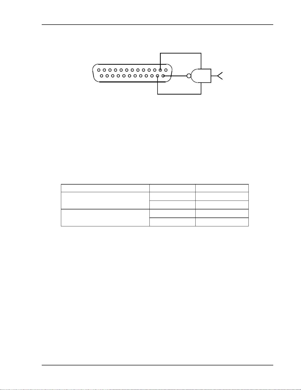
2.3.9 Programming the Shutdown Function
2131
GND
14
25
15
+5V
Figure 2–3. Using Shutdown with a DC Input (Positive Logic)
2.3.10 TTL Shutdown
Set up for Shutdown input signal as follows:
1. Connect the shutdown signal source to the ISOLATED ANALOG PROGRAMMER
connector, J4, with positive to Pin-14 and the return to Pin-2.
2. Set switch SW1-6 to select the desired logic as defined in the following table.
Switch SW1-6 Setting Signal Level Output Condition
Low OFF
OFF (0) = Negative Logic
High ON
High OFF
ON (1) = Positive Logic
Low ON
M51A Option 2-15
Page 28

Isolated Analog Programmer Operation DLM-E Series and DCS-E Series
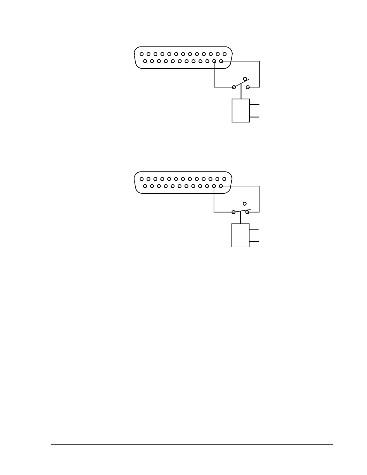
2.3.11 Shutdown Application – Contact Closure
An external relay, whether normally open or normally closed, may be used to activate the
Shutdown circuit. Either positive or negative logic may be used.
Set up for Shutdown input signal as follows:
1. Connect one side of the external relay to pin 15 (+16 VDC Auxiliary Output) on
connector J4. Connect the other side of the relay to pin 14 (Remote Shutdown Input).
2. Set rear panel DIP switch SW1-6 to select the desired circuit logic as defined in the
following table.
Relay Switch SW1-6 Setting Relay Coil State Output
ON (1) (Positive Logic)
Normally Open Relay
OFF (0) (Negative Logic)
ON (1) (Positive Logic)
Normally Closed Relay
OFF (0) (Negative Logic)
Energized OFF
De-energized ON
Energized ON
De-energized OFF
Energized ON
De-energized OFF
Energized OFF
De-energized ON
Figure 2–4.
13 1
14
25 15
Using Shutdown with Contact Closure of a Normally OPEN Relay (SW1-6 ON)
2-16 M51A Option
Page 29
DLM-E Series and DCS-E Series Isolated Analog Programmer Operation
13 1
14
25 15
Figure 2–5.
Using Shutdown with Contact Closure of a Normally OPEN Relay (SW1-6 OFF)
Figure 2–6.
13 1
14
25 15
Using Shutdown with Contact Closure of a Normally CLOSED Relay (SW1-6 ON)
M51A Option 2-17
Page 30
Isolated Analog Programmer Operation DLM-E Series and DCS-E Series
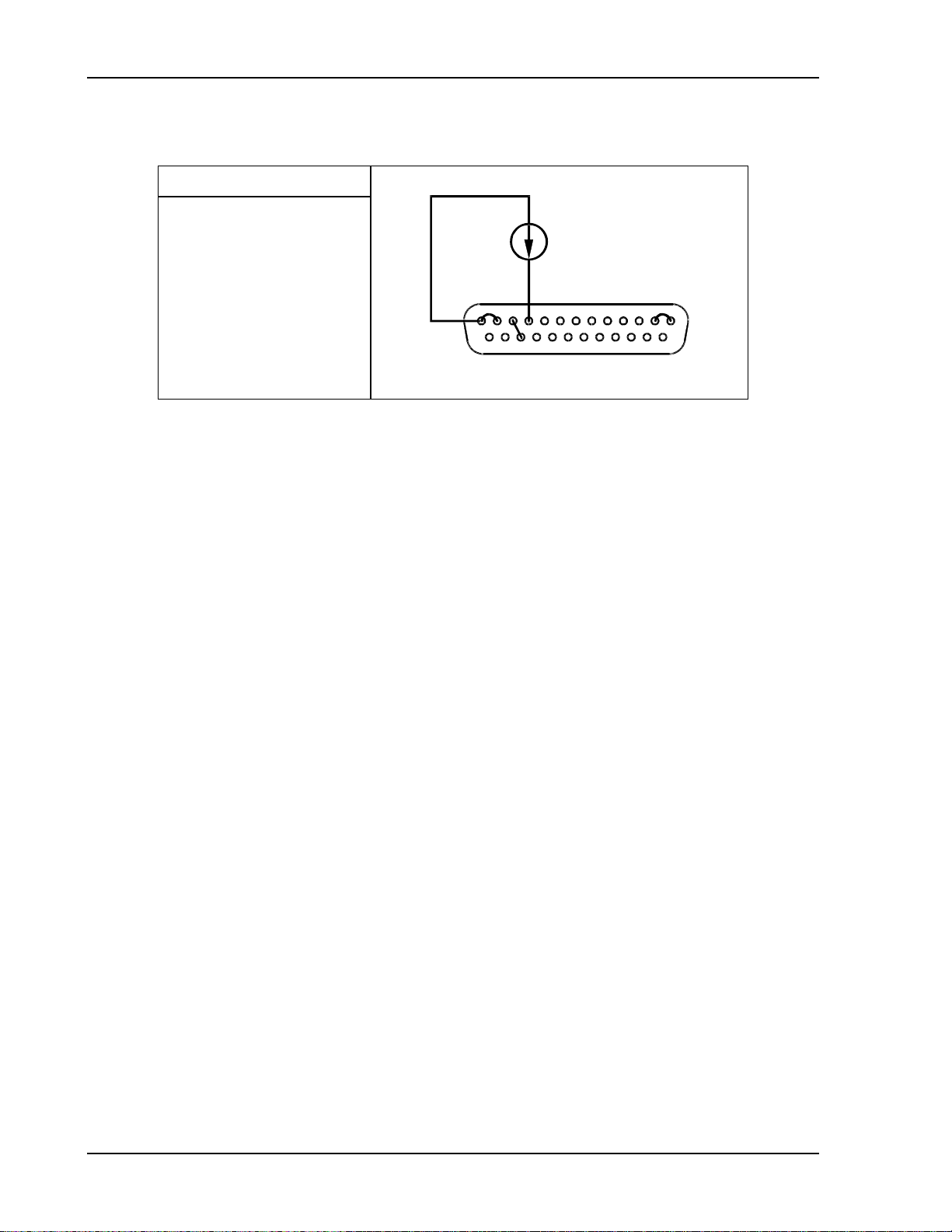
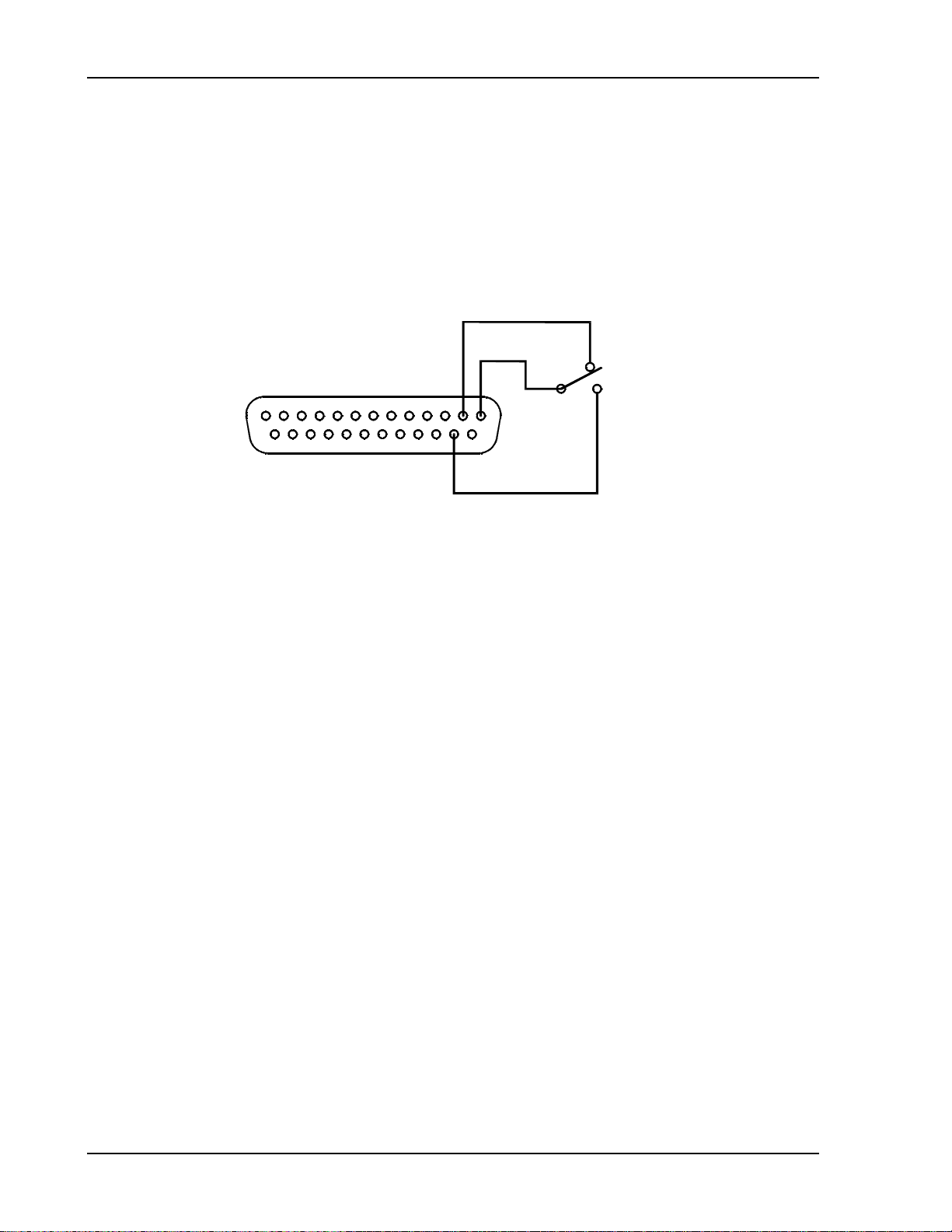
2.3.12 Local/Remote Application
An external relay or switch may be used to select the Local/Remote function.
1. Connect one side of the contacts to Pin-15 (+16 VDC Auxiliary Output) on connector J4.
Connect the other contact to Pin-2. Connect the wiper to Pin-1, Analog Control Input.
2. Remote operation results when Pin-1 is low (Pin 1-2) and local supply operation results
when Pin-1 is high (Pin1-15).
Remote
13 1
2
Local
25 15
14
Figure 2–7 Using Local/Remote Operation with Contact Closure
2-18 M51A Option
Page 31
DLM-E Series and DCS-E Series Isolated Analog Programmer Operation
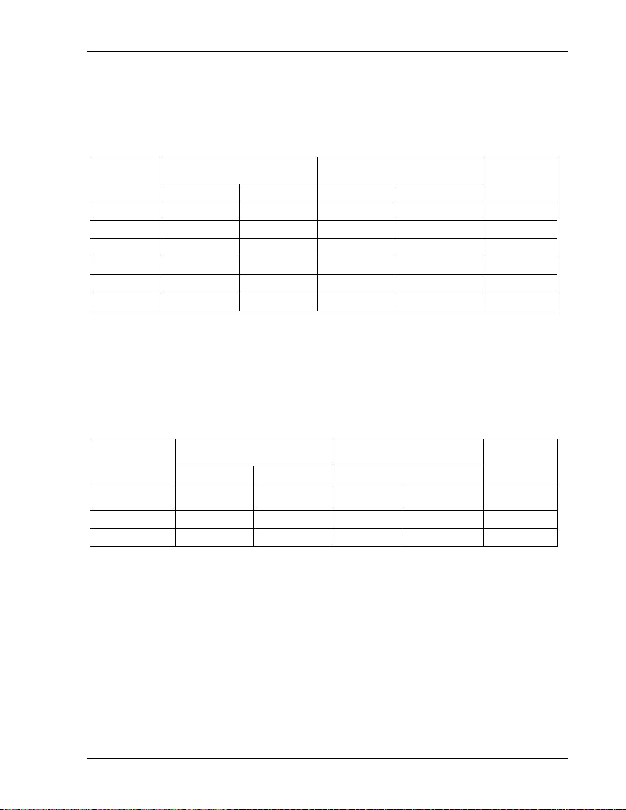
2.4 Remote Monitoring
Analog signals are available for monitoring the output voltage and current. These signals vary
proportionally to the output parameters, and have user selectable ranges of 0-5VDC, 0-10VDC,
or 4-20mA for an output change from zero to full scale. Refer to Table 2–3 for information on
configuring the monitors.
Output
Monitor
Signal
Voltage Pin-19 Pin-12 4 - V MON ON (1) 0-10VDC
Voltage Pin-19 Pin-12 4 - V MON OFF (0) 0-5VDC
Voltage Pin-4 Pin-12 N/A N/A 4-20mA
Current Pin-7 Pin-12 5 - I MON ON (1) 0-10VDC
Current Pin-7 Pin-12 5 - I MON OFF (0) 0-5VDC
Current Pin-24 Pin-12 N/A N/A 4-20mA
Isolated Analog
Programmer Connector J4
Signal Return Position Setting
Table 2–3. Remote Monitoring
SW1 SETUP Switch
Signal
Range
2.5 Remote Digital Status Signals
Digital signals are available for remote monitoring the operational status of the unit. Refer to
Table 2–4 for information on the characteristics of the signals.
Status
Indicator
Signal
VOLTAGE-
MODE
OVP Pin-17 Pin-6 5V 0V 1kΩ
FAULT Pin-18 Pin-6 5V 0V 1kΩ
Isolated Analog Interface
Connector J4
Signal Return Asserted Not Asserted
Pin-5 Pin-6 5V 0V 1kΩ
Table 2–4. Remote Digital Status Signals
Logic Levels (with No
Signal Output Current)
Output
Resistance
M51A Option 2-19
Page 32

Isolated Analog Programmer Operation DLM-E Series and DCS-E Series
This page intentionally left blank.
2-20 M51A Option
 Loading...