

Page 1
Reference Manual
Compact Temperature Calibrator
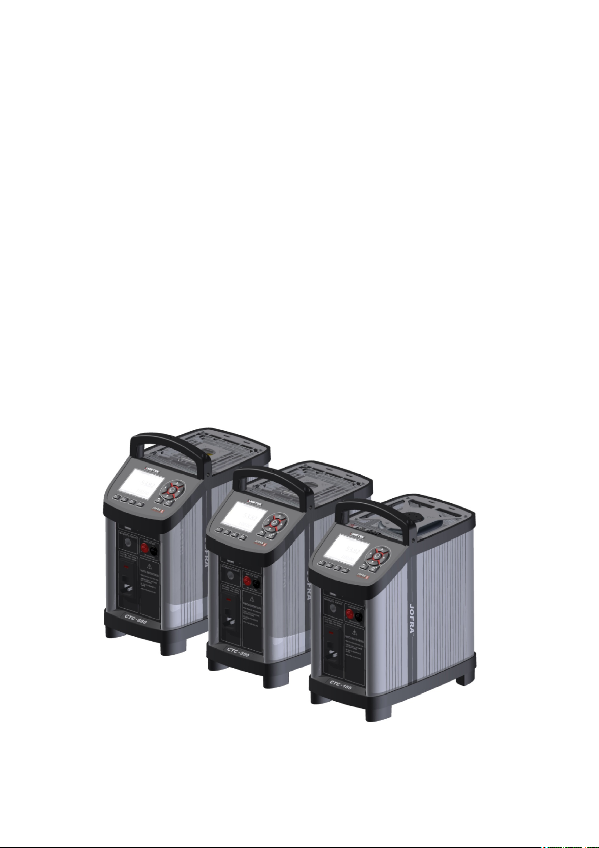
Jofra CTC-155/350/660 A/C
Page 2
Reference Manual
Compact Temperature Calibrator
JOFRA CTC-155/350/660 A/C
Copyright 2016 AMETEK Denmark A/S
Page 3
About this manual….
The structure of the manual
This reference manual is aimed at users who are familiar with AMETEK calibrators, as well
as those who are not. The manual is divided into 11 sections which describe how to set up,
operate, service and maintain the calibrator. The technical specifications are described and
accessories may be ordered from the list of accessories.
Safety symbols
This manual contains a number of safety symbols designed to draw your attention to
instructions which must be followed when using the instrument, as well as any risks involved.
Warning
Conditions and actions that may compromise the safe use of the
instrument and result in considerable personal or material damage.
Caution…
Conditions and actions that may compromise the safe use of the
instrument and result in slight personal or material damage.
Note…
Special situations which demand the user’s attention.
129375 00 2016-05-18 2
Page 4

List of contents
1.0 Introduction ................................................................................................................................. 4
1.1 Warranty ................................................................................................................................................ 5
1.2 Receiving the Compact Temperature Calibrator ................................................................................... 6
1.3 Dimensioning drawing ........................................................................................................................... 7
2.0 Safety instructions ...................................................................................................................... 8
3.0 Setting up the calibrator for use .............................................................................................. 11
3.1 Preparing the calibrator ....................................................................................................................... 11
3.2 Choosing an insertion tube ................................................................................................................. 12
3.2.1 Standard insertion tubes ........................................................................................................ 13
3.3 Inserting the sensor ............................................................................................................................. 14
3.4 Programming intelligent STS sensors ................................................................................................. 16
4.0 Calibrator Interface ................................................................................................................... 17
4.1 Keypad - Functions ............................................................................................................................. 17
4.2 Display - Functions .............................................................................................................................. 17
4.2.1 Main screen temperature values ............................................................................................ 18
4.2.2 Stability of temperature values ............................................................................................... 18
4.3 Input/Output Connections ................................................................................................................... 19
5.0 Operating the calibrator ........................................................................................................... 20
5.1 Operating principle .............................................................................................................................. 20
5.1.1 System menu .......................................................................................................................... 21
5.2 Starting the calibrator .......................................................................................................................... 23
5.3 Selecting a TRUE – reference sensor (C-models only) ...................................................................... 23
5.4 Stability setting .................................................................................................................................... 25
5.5 Selecting the set-temperature ............................................................................................................. 25
5.5.1 Editing the preset set-temperature ......................................................................................... 26
5.6 Auto Step function ............................................................................................................................... 28
5.6.1 Running an Auto Step test ..................................................................................................... 28
5.6.2 The calibrator's Auto Step procedure ..................................................................................... 29
5.7 Switch Test function ............................................................................................................................ 31
5.7.1 Running a Switch Test ........................................................................................................... 31
5.7.2 The calibrator's Switch Test procedure .................................................................................. 33
6.0 Storing and transporting the calibrator .................................................................................. 34
7.0 Error messages (List of alarms) .............................................................................................. 37
8.0 Returning the calibrator for service ........................................................................................ 40
9.0 Maintenance .............................................................................................................................. 42
9.1 Replacing the main fuses .................................................................................................................... 42
9.2 Maintenance mode .............................................................................................................................. 43
9.3 Cleaning .............................................................................................................................................. 47
9.4 Adjusting and calibrating the instrument ............................................................................................. 48
9.5 Maintenance of STS-reference sensor ............................................................................................... 48
10.0 Technical specifications .......................................................................................................... 49
11.0 List of accessories .................................................................................................................... 56
129375 00 2016-05-18 3
Page 5

1.0 Introduction
A
Congratulations on your new AMETEK JOFRA CTC Calibrator!
With the AMETEK JOFRA Compact Temperature Calibrator, you have chosen an extremely
effective instrument which we hope will live up to all your expectations.
This CTC calibrator is a fast, timesaving, and reliable true industrial temperature calibrator
designed for on-site use.
During the past several years, we have acquired extensive knowledge of industrial temperature
calibration. This expertise is reflected in our products which are all designed for daily use in an
industrial environment. Please note that we would be very interested in hearing from you if you
have any ideas or suggestions for changes to our products.
This reference manual applies to the following instruments:
JOFRA CTC-155 A – Temperature calibrator
JOFRA CTC-155 C – Temperature calibrator with reference sensor input
JOFRA CTC-350 A – Temperature calibrator
JOFRA CTC-350 C – Temperature calibrator with reference sensor input
JOFRA CTC-660 A – Temperature calibrator
JOFRA CTC-660 C – Temperature calibrator with reference sensor input
The calibrator has the following features and functions:
Wide temperature range
Fast heating and cooling time as well as a short stabilization time
Signal input for external reference sensor, which makes it possible to improve accuracy even
more.
External sensor control for running in two modes.
Multi-Information colour Display and Function keys
Useful features such as Set function, Preset mode, Auto Switch Test and Auto Stepping
IRI – Intelligent Recalibration Information
Plug and play STS reference sensors with memory chip
Broad range of inserts
Reference sensor protection
Silent mode operation
JOFRACAL calibration software
Protective carrying case with compartments for inserts, cables, manuals, plugs etc.
ISO-9001 certified
METEK Denmark A/S was ISO-9001 certified in September 1994 by Bureau Veritas
Certification Denmark.
129375 00 2016-05-18 4
Page 6

CE-label
Your new temperature calibrator bears the CE label and conforms to the
Electromagnetic Compatibility (EMC) Directive and the Low Voltage Directive.
Technical assistance
Please contact the dealer from whom you acquired the instrument if you require technical
assistance.
1.1 Warranty
This instrument is warranted against defects in workmanship, material and design for two (2)
years from date of delivery to the extent that AMETEK will, at its sole option, repair or replace
the instrument or any part thereof which is defective, provided, however, that this warranty shall
not apply to instruments subjected to tampering or, abuse, or exposed to highly corrosive
conditions.
THIS WARRANTY IS IN LIEU OF ALL OTHER WARRANTIES WHETHER EXPRESS OR
IMPLIED AND AMETEK HEREBY DISCLAIMS ALL OTHER WARRANTIES, INCLUDING,
WITHOUT LIMITATION, ANY WARRANTY OF FITNESS FOR A PARTICULAR PURPOSE OR
MERCHANTABILITY. AMETEK SHALL NOT BE LIABLE FOR ANY INCIDENTAL OR
CONSEQUENTIAL DAMAGES, INCLUDING, BUT NOT LIMITED TO, ANY ANTICIPATED OR
LOST PROFITS.
This warranty is voidable if the purchaser fails to follow any and all instructions, warnings or
cautions in the instrument’s User Manual.
If a manufacturing defect is found, AMETEK will replace or repair the instrument or replace any
defective part thereof without charge; however, AMETEK’s obligation hereunder does not
include the cost of transportation, which must be borne by the customer. AMETEK assumes
no responsibility for damage in transit, and any claims for such damage should be presented
to the carrier by the purchaser.
129375 00 2016-05-18 5
Page 7

1.2 Receiving the Compact Temperature Calibrator
When you receive the instrument…
1) Unpack and check the calibrator and the accessories carefully.
2) Check the parts according to the list shown below.
If any of the parts are missing or damaged, please contact the dealer who sold
you the calibrator.
You should receive:
1 CTC Calibrator
1 USB memory stick containing electronic Reference manual and software
package JOFRACAL
1 mains cable
1 sets of test leads and test clips (black and red)
Thermal protection shield (CTC-660 only)
1 tool for insertion tube
1 USB cable
1 Calibration certificate (International traceable)
When reordering, please specify the part numbers according to the list of accessories,
section 11.0
129375 00 2016-05-18 6
Page 8
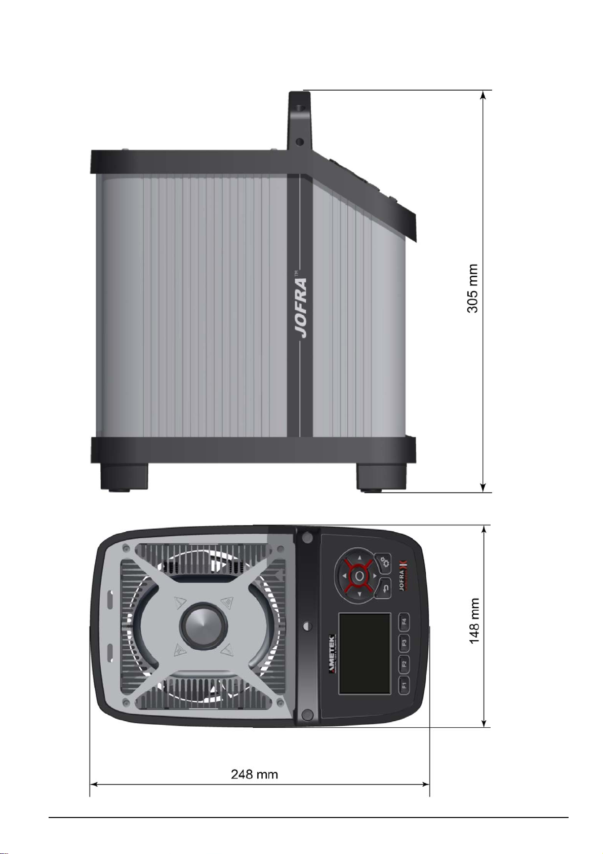
1.3 Dimensioning drawing
129375 00 2016-05-18 7
Page 9
2.0 Safety instructions
Read this manual carefully before using the instrument!
Please follow the instructions and procedures described in this manual. They are
designed to allow you to get the most out of your calibrator and avoid any personal
injuries and/or damage to the instrument.
Disposal – WEEE Directive
These calibrators contain Electrical and Electronic circuits and must be recycled or
disposed of properly (in accordance with the WEEE Directive 2002/96/EC).
Warning
About the use:
The calibrator must not be used for any purposes other than those described in
this manual, as it might cause a hazard.
The calibrator has been designed for indoor use only and is not to be used in
wet locations.
The calibrator is not to be used in hazardous areas, where vapour or gas leaks,
etc. may constitute a danger of explosion.
The calibrator is not designed for operation in altitudes above 2000 meters.
The calibrator is a CLASS I product and must be connected to a mains outlet with
a protective earth connection. Ensure the ground connection of the calibrator is
properly connected to the protective earth before switching on the calibrator.
Always use a mains power cable with a mains plug that connects to the protective
earth.
To ensure the connection to protective earth any extension cord used must also
have a protective earth conductor.
Only use a mains power cord with a current rating as specified by the calibrator
and which is approved for the voltage and plug configuration in your area.
Before switching on the calibrator make sure that it is set to the voltage of the
mains electricity supply.
Always position the calibrator to enable easy and quick disconnection of the
power source (mains inlet socket).
The calibrator must be kept clear within an area of 20 cm on all sides and 1 metre
above the calibrator due to fire hazard.
Never use heat transfer fluids such as silicone, oil, paste, etc. in the dry-block
calibrators. These fluids may penetrate the calibrator and cause electrical hazard,
damage or create poisonous fumes.
The calibrator must be switched off before any attempt to service the instrument
is made. There are no user serviceable parts inside the calibrator.
When cleaning the well or the insertion tube, REMEMBER to wear goggles when
using compressed air!
About the frontpanel:
The connectors, on the front panel of the calibrator, must NEVER be connected to
a voltage source.
Thermostats connected to the switch test input must not be connected to any
other voltage source during a test.
129375 00 2016-05-18 8
Page 10
About insertion tubes and insulation plugs:
Never leave hot insertion tubes, which have been removed from the calibrator,
unsupervised – they may constitute a fire hazard or personal injury.
If you intend to store the calibrator in the aluminium carrying case after use, you
must ensure that the instrument has cooled down to a temperature below
50°C/122°F before placing it in the carrying case.
Never place a hot insertion tube in the optional carrying case.
Use only insulation plugs supplied by AMETEK Denmark A/S.
About the fuses:
The fuse box must not be removed from the power control switch until the mains
cable has been disconnected.
The two main fuses must have the specified current and voltage rating and be of
the specified type. The use of makeshift fuses and the short-circuiting of
fuse holders are prohibited and may cause a hazard.
Caution – Hot surface
This symbol is visible on the grid plate.
Do not touch the grid plate, the well or the insertion tube as the calibrator is
heating up – they may be very hot and cause burns.
Do not touch the tip of the sensor when it is removed from the insertion tube/well
– it may be very hot and cause burns.
Do not touch the handle of the calibrator during use – it may be very hot and
cause burns.
Over 50°C/122°F
If the calibrator has been heated up to temperatures above 50°C/122°F, you must
wait until the instrument reaches a temperature below 50°C/122°F before you
switch it off.
Do not remove the insert from the calibrator before the insert has cooled down to
less than 50°C/122°F.
Caution – Cold surface
Below 0°C/32°F (applies only to the CTC-155 C models)
Do not touch the well or insertion tube when these are below 0°C/32°F - they
might create frostbite.
If the calibrator has reached a temperature below 0°C/32°F, ice crystals may form
on the insertion tube and the well. This, in turn, may cause the material surfaces
to oxidize
To prevent this from happening the insertion tube and the well must be dried. This
is done by heating up the calibrator to 100°C/212°F until all water left has
evaporated.
Remove the insulation plug while heating up.
It is very important that humidity in the well and insertion tube is removed to
prevent corrosion and frost expansion damages.
129375 00 2016-05-18 9
Page 11

Caution…
A
About the use:
Do not use the instrument if the internal fan is out of order.
Before cleaning the calibrator, you must switch it off, allow it to cool down and
remove all cables.
bout the well, insertion tube and grid plate:
The well and the insertion tube must be clean and dry before use.
Do not pour any form of liquids into the well. It might damage the well or cause
a hazard.
Scratches and other damage to the insertion tubes should be avoided by storing
the insertion tubes carefully when not in use.
The insertion tube must never be forced into the well. The well could be
damaged as a result, and the insertion tube may get stuck.
Before using new insertion tubes for the calibration, the insertion tubes must be
heated up to maximum temperature 350°C(662°F) / 660°C (1220°F) for a period
of minimum 30 minutes (CTC-350/660 only).
The insertion tube must always be removed from the calibrator after use.
The humidity in the air may cause corrosion oxidation on the insertion tube
inside the instrument. There is a risk that the insertion tube may get stuck if this
is allowed to happen.
If the calibrator is to be transported, the insertion tube must be removed from
the well to avoid damage to the instrument.
Note…
The product liability only applies if the instrument is subject to a manufacturing
defect. This liability becomes void if the user fails to follow the instructions set out
in this manual or uses unauthorised spare parts.
129375 00 2016-05-18 10
Page 12
3.0 Setting up the calibrator for use
3.1 Preparing the calibrator
Warning
The calibrator has been designed for indoor use only and is not to be used in
wet locations.
The calibrator is not to be used in hazardous areas, where vapour or gas leaks,
etc. may constitute a danger of explosion.
The calibrator is not designed for operation in altitudes above 2000 meters.
The calibrator is a CLASS I product and must be connected to a mains outlet with
a protective earth connection. Ensure the ground connection of the calibrator is
properly connected to the protective earth before switching on the calibrator.
Always use a mains power cable with a mains plug that connects to the protective
earth.
To ensure the connection to protective earth any extension cord used must also
have a protective earth conductor.
Only use a mains power cord with a current rating as specified by the calibrator
and which is approved for the voltage and plug configuration in your area.
Before switching on the calibrator make sure that it is set to the voltage of the
mains electricity supply.
Always position the calibrator to enable easy and quick disconnection of the
power source (mains inlet socket).
The calibrator must be kept clear within an area of 20 cm on all sides and 1 metre
above the calibrator due to fire hazard.
Note…
The instrument must not be exposed to draughts.
When setting up the calibrator, you must…
Place the calibrator on an even horizontal surface where you intend to use it.
Caution…
Do not use the instrument if the internal fan is out of order.
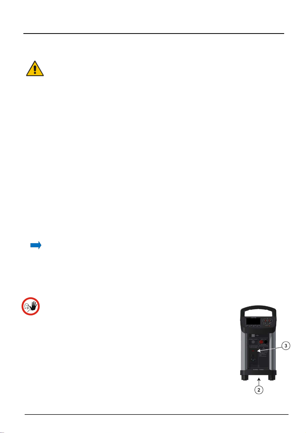
Ensure a free supply of air to the internal fan located at the bottom
of the instrument (pos. 2). The area around the calibrator should be
free of draught, dirt, flammable substances etc.
Check that the fuse size corresponds to the applied voltage on (pos.
3). The fuse is contained in the power control switch (on/off switch
(230V/115V)). To check; do as follows (see Fig. 1):
129375 00 2016-05-18 11
Page 13
Warning
The two main fuses must have the specified current and voltage rating and be of the
specified type. The use of makeshift fuses and the short-circuiting of fuse holders are
prohibited and may cause a hazard.
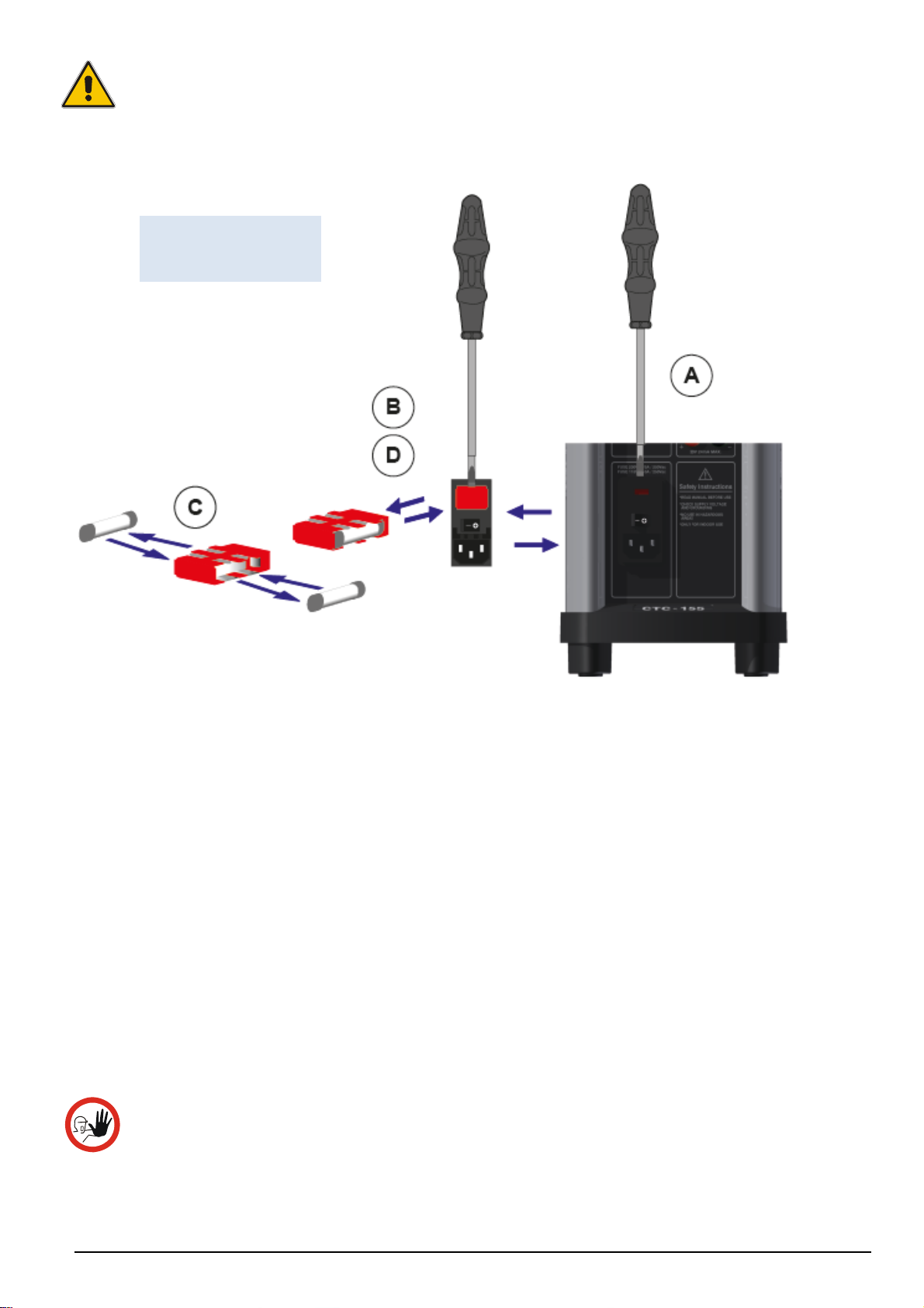
A. Open the fuse box lid using a screwdriver.
B. Take out the fuse box.
C. Remove both fuses replacing them with two new fuses. These must be identical
D. Slide the fuse box back into place.
Fig. 1
Changing fuses
and should correspond to the line voltage. See section 11.0.
The calibrator is now ready for use.
Check that the earth connection for the instrument is present and attach the cable.
Select an insertion tube with the correct bore diameter. See section 3.2 for information
on how to select insertion tubes.
3.2 Choosing an insertion tube
Caution…
To get the best results out of your calibrator, the insertion tube dimensions, tolerance
129375 00 2016-05-18 12
and material are critical. We highly advise using the JOFRA insertion tubes, as they
guarantee trouble free operation. Use of other insertion tubes may reduce
performance of the calibrator and cause the insertion tube to get stuck.
Page 14
Caution…
Before using new insertion tubes for the calibration in the CTC-350/660 instruments
the insertion tubes must be heated up to maximum temperature 350°C(662°F) /
660°C (1220°F) for a period of minimum 30 minutes.
Insertion tubes are selected on the basis of the diameter of the sensor to be calibrated.
Use the table for insertion tubes in section 3.2.1 to find the correct parts number.
Alternatively, you may order an undrilled insertion tube and drill the required hole yourself. The
finished dimension should be as follows:
Sensor diameter ød+0.2 +0.05 / -0.00 mm.
Reference sensor hole ø4.2mm +0.05 / -0.00 mm
3.2.1 Standard insertion tubes
Caution…
To get the best results out of your calibrator, the insertion tube dimensions, tolerance
and material are critical. We highly advise using the JOFRA insertion tubes, as they
guarantee trouble free operation. Use of other insertion tubes may reduce
performance of the calibrator and cause the insertion tube to get stuck.
PARTS NO. FOR STANDARD INSERTION TUBES – SINGLE HOLES
Sensor
size
3 mm
4 mm
5 mm
6 mm
7 mm
8 mm
9 mm
10 mm
11 mm
12 mm
13 mm
14 mm
15 mm
16 mm*
18 mm*
20 mm*
CTC-155 CTC-350 CTC-660
129407
129408
129409
129410
129411
129412
129413
129414
129415
129416
129417
-
-
-
-
-
129429
129430
129431
129432
129433
129434
129435
129436
129437
129438
129439
129440
129441
129442
129443
129444
129459
129460
129461
129462
129463
129464
129465
129466
129467
129468
129469
129470
129471
129472
129473
129474
Sensor
size
Undrilled
Undrilled/ref. hole
1/8”
3/16”
1/4”
5/16”
3/8”
7/16”
1/2”
9/16”
5/8”
11/16”*
13/16”*
3/4”*
CTC-155 CTC-350 CTC-660
129418
129419
129420
129421
129422
129423
129424
129425
129426
129427
129428
-
-
-
129445
129446
129447
129448
129449
129450
129451
129452
129453
129454
129455
129456
129457
129458
129475
129476
129477
129478
129479
129480
129481
129482
129483
129484
129485
129486
129487
129488
The CTC-155 single-hole insertion tubes are delivered with a matching insulation plug.
*Note: Insertion tubes without reference holes.
129375 00 2016-05-18 13
Page 15
PART NO. FOR STANDARD INSERTION TUBES – MULTI-HOLE
Description
Metric Type 1
Sensor size
3, 4, 5, 6, 9 mm and
4mm REF
Inch Type 2
Sensor size
1/8”, 3/16”, 1/4”, 3/8” and
4 mm REF
CTC-155
129489 129491 129493
129490
CTC-350
129492
CTC-660
129494
The CTC-155 multi-hole insertion tubes are delivered with a matching insulation plug.
3.3 Inserting the sensor
Before inserting the sensor and switching on the calibrator, please note the following important
warning:
Warning
Never use heat transfer fluids such as silicone, oil, paste, etc. in the dry-block
calibrators.
These fluids may penetrate the calibrator and cause electrical hazard, damage or
create poisonous fumes.
Never try to modify the insulation plugs to make them fit the sensor. Use only
insulation plugs supplied by AMETEK Denmark A/S.
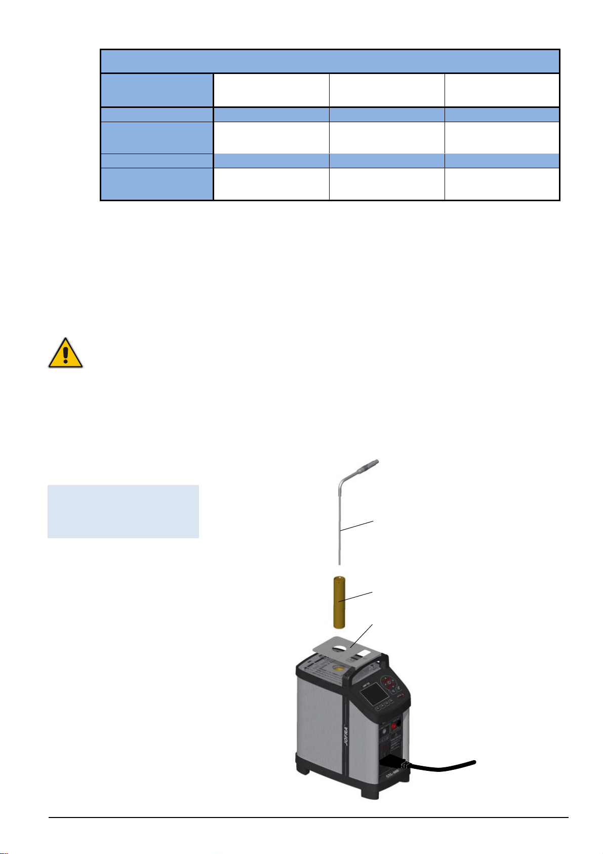
Insert the sensor as shown below in fig. 2.
Fig. 2
Inserting sensor and
insertion tube
Sensor under test
Insertion tube
Thermal protection shield
129375 00 2016-05-18 14
Page 16
Check that the insulation plug fits the diameter of the sensor. Otherwise replace it (CTC-155
only).
In order to spare the sensor and its connections it is recommended to use a thermal
protection shield (129264) at high temperatures (CTC-350/660 only).
Caution…
The well and the insertion tube must be clean before use.
Do not pour any form of liquids in the well. It might damage the well.
Scratches and other damage to the insertion tubes should be avoided by storing
the insertion tubes carefully when not in use.
The insertion tube must never be forced into the well. The well could be damaged
as a result, and the insertion tube may get stuck.
Caution – Hot surface
Do not touch the grid plate, the well or the insertion tube as the calibrator is
heating up – they may be very hot and cause burns.
Do not touch the tip of the sensor when it is removed from the insertion tube/well
– it may be very hot and cause burns.
Do not touch the handle of the calibrator during use – it may be very hot and
cause burns.
Do not remove the insertion tube from the calibrator before the insertion tube has
cooled down to less than 50°C/122°F.
Caution – Cold surface
Below 0°C/32°F (applies only to the CTC-155 models)
Do not touch the well or insertion tube when these are below 0°C/32°F - they might
create frostbite.
If the calibrator has reached a temperature below 0°C/32°F, ice crystals may form
on the insertion tube and the well. This, in turn, may cause the material surfaces to
oxidize
To prevent this from happening the insertion tube and the well must be dried. This is
done by heating up the calibrator to 100°C/212°F until all water left has evaporated.
Remove the insulation plug while heating up.
It is very important that humidity in the well and insertion tube is removed to prevent
corrosion and frost expansion damages.
129375 00 2016-05-18 15
Page 17

3.4 Programming intelligent STS sensors
Use the configuration software CON050 supplied with CTC to program and to update
calibration information in intelligent STS sensors.
For instructions read the software manual for CON050 installed on the USB key.
129375 00 2016-05-18 16
Page 18
play
y
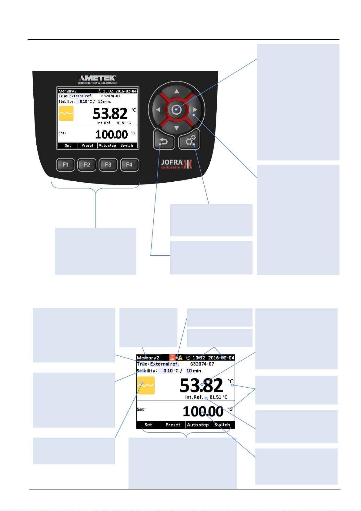
4.0 Calibrator Interface
4.1 Keypad - Functions
Function keys
F1, F2, F3, F4
To operate the horizontal
menu bar use the
Functions keys.
System menu key
Press the key to enter the
System menu.
Back key
Press the key to cancel a
selection or return to
previous menu.
Arrow Keys
Serve different functions
depending on the mode of
operation.
Navigation mode: Use the
four keys to move the
cursor in the desired
direction.
Edit mode: The Up and
Down Arrow keys scroll
through the lists of options.
If entering a number, the
Left and Right Arrow keys
move the cursor one
character in the desired
direction.
Action key / Enter key
Action function: Open and
close edit fields or a menu
button. The action key also
accepts the selected
option or entered value.
Enter function: Accept
selected options or
entered values. When a
value is entered with the
Enter Key the cursor
selects the next
configurable field in the
list.
4.2 Display - Functions
Reference sensor info
Shows the reference sensor
selected. The serial number
of the external reference
sensor is read from the
intelligent reference sensor
and displayed in this field.
“Time to stable”
Selection
Shows the selected
specified stability criteria
and states a time when the
stable situation can be
achieved.
Process Indicator
Indicates the status of the
current process.
Memory reading
Shows the current
memory selected
from the System
menu.
Warning/Error
s
mbols. See 4.2.2
Real Time Clock and
date dis
Horizontal menu bar
Provides you with the relevant menu
options that can be selected at the
present point.
selected and activated by pressing the
function keys (F1, F2, F3 and F4).
Each option can be
.
True temperature
reading
Shows the numeric value
of the temperature being
measured. Can be either
the internal reference
sensor or an external
reference sensor.
Units
Shows the unit of the
current measurement.
Internal Reference
temperature reading
Shows the temperature of
the well.
Set temperature reading
Shows the numeric value
of the current set
temperature selected.
129375 00 2016-05-18 17
Page 19

4.2.1 Main screen temperature values
Two temperatures are always displayed:
TRUE temperature: This is the reference temperature of the calibrator. The TRUE
temperature can either be the internal reference or the external reference.
SET temperature: This is the target temperature for the well. SET temperature displays the
last value entered. If no value has been entered previously, "---,--" is displayed.
Additional temperatures displayed:
If External reference is selected as TRUE temperature, the temperature of the internal
reference is also displayed.
4.2.2 Stability of temperature values
The stability of the TRUE and SENSOR temperatures are indicated by the following
messages:
"Not stable": Indicates that the measured temperature is not yet within the specified
stability criteria.
Indicates "Time to stable": The temperature changes are within the specified stability
criteria (see section 10.0) and states a time (in minutes and seconds) when the stable
situation can be achieved.
Indicates that the “stable” situation is achieved and for how long the calibrator has
been stable. When the calibrator has been stable for more than 99 minutes, only the
stable sign is displayed (time is no longer displayed).
If External reference is selected as TRUE, the stability criteria will refer to this.
The criteria can be changed, however, if the temperature stability criteria is set
wider or the stability time is set shorter, the calibrator may not reach the SET
temperature.
If “Use stability criteria” is set to “Yes” for the SENSOR, the automatic calibration
function will continue to next temperature step only when both TRUE and
SENSOR indicate stability.
When the instrument is heating up and cooling down indication of this will be shown as
following symbols:
The instrument is heating up.
The instrument is cooling down (CTC-155 only).
The instrument is cooling down (CTC-350/660 only).
Heating and cooling symbols will be displayed in the upper black info bar when:
the well temperature is below 5°C.
the well temperature is above 45°C.
129375 00 2016-05-18 18
Page 20

Warning and error symbols will be displayed in the upper black info bar indicating that action
needs to be taken:
Warning symbol.
Error symbol.
If a warning or an error symbol occurs during operation, a list of alarms will be displayed
showing the warning and/or error messages. See section 7.0 – Error messages.
Note…
A warning will always surpass an error, even if the error occurs after the warning.
4.3 Input/Output Connections
Fig. 3
Input and Output
Device
USB 2.0 Device Port, 1 x
USB.
Reference Sensor
Input for reference
sensor.
Power Control Switch
With a cable connection
and On/Off switch. It also
contains the main fuse.
See section 3.1 for
information on how to
change the fuse. The text
above the Power Control
Switch indicates the fuse
value.
Warning
The input terminals must NEVER be connected to voltage exceeding 30V with
reference to ground.
Switch Test
Connection for
thermostat switch test.
Note that this connection
is for voltage free
switches.
129375 00 2016-05-18 19
Page 21

5.0 Operating the calibrator
5.1 Operating principle
Warning Caution…
Please inspect the Safety Instructions in section 2.0 before using the instrument.
The calibrator is operated using the Functions keys, the Arrow keys and the
Action/Enter key.
1. Press the Functions keys to operate the horizontal menu bar.
2. Press any of the (Arrow) keys to enter Navigation Mode. Editable fields will be
highlighted in blue.
3. Use the (Arrow) keys to move between the configurable fields within the
display. Selected fields will be highlighted in dark blue..
4. Press the (Enter) key to access the selected field for editing.
5. Use the (Up) and (Down) Arrow keys to select a new value.
6. Press the (Enter) key to accept the new value
7. To exit the Navigation Mode press the (Back) key. The (Back) key is also
used to cancel a selection or to return to a previous menu.
129375 00 2016-05-18 20
Page 22

5.1.1 System menu
The System menu can be accessed at any stage of operation:
1. Press the (System) key to display the System menu.
2. Use the (Up) and (Down) Arrow keys to scroll in the list.
System Settings menu
1. Use the (Enter) key and the (Up) and (Down) Arrow keys to access
editable fields, select new values and accept new values.
Note…
If the current set-temperature is higher than the new max-temperature, you will
need to adjust the set-temperature. The instrument will immediately begin to
cool (if required) as soon as the new max-temperature is accepted.
The calibration interval can be set between 1 and 99 months. When the
calibration interval is exceeded, a yellow warning symbol will appear in
the upper part of the display. The recalibration interval is not used for the
external reference sensor. The interval for this sensor is stored in the intelligent
sensor.
If the Ext. reference input setting is disabled, it will not be possible to select the
external reference or SET follows true from the Mode menu. Only the internal
reference can be selected and displayed in the main display (C-models only).
129375 00 2016-05-18 21
Page 23

If Silent mode is selected, the cooling speed will be reduced.
Presets menu
The preset temperatures can be changed manually using the (Arrows) keys.
Note…
Temperature range is limited by Min. SET Temp. and Max. SET Temp. settings
editable in the System Settings menu and by the temperature range of the
external reference sensor, if connected.
System Info menu
In the System Info menu important information such as serial numbers and
calibration dates of both the instrument and the external reference sensor are
given.
It is not possible to edit any fields in this menu.
Store menu (Save Settings)
After you have configured the instrument, you can save the setup for future use
using the Store function.
1. Use the (Up) and (Down) Arrow keys to select the Memory-setup you want to
modify, and press (Save). The new configuration is now saved.
F3
2. You can change the name of the highlighted saved setup by pressing (Enter),
and then using the (Up) and (Down) Arrow keys to change the characters.
129375 00 2016-05-18 22
Page 24

The name is limited to seven (7) characters.
3. Press to save the new name.
F3
Recall menu
To recall your memory setups select the Recall function.
1. Use the (Up) and (Down) Arrow keys to to scroll in the setup-list.
2. Select the requested setup, and press (Enter).
The name of the setup will appear in the upper-left corner of the display.
If selecting the Factory default function the active setup will be reset and change to
the initial setting.
5.2 Starting the calibrator
Switch on the calibrator using the power control switch (see section 4.3).
A start up screen is displayed and then replaced with the main menu screen:
The functions in the horizontal menu bar are available using the Functions soft keys
F1 – F4. For Operating principle – See section 5.1.
5.3 Selecting a TRUE – reference sensor (C-models only)
1. Press one of the (Arrow) keys and the (Enter) key to access the Mode
menu.
129375 00 2016-05-18 23
Page 25

You can choose between one of the following sensor constellations:
Internal reference source (A and C models)
External reference source (C models only)
SET follows TRUE (C-models only)
Internal reference source
The internal reference sensor will be displayed as the TRUE value on the main
screen.
The calibrator has a set of internal stability criteria it shall meet before stability is
indicated. The stability time may be set beyond the internal stability criteria.
The stability time can be set (in minutes) using integers from 5 – 99
External reference source (C-models only)
The TRUE value on the main screen will be read from the Intelligent Reference
Sensor connected to the REF. INPUT on the front panel (see section 4.3, fig 3). The
calibrator automatically reads the calibration data and serial number of the Sensor.
SET follows TRUE (C-models only)
This function enables you to reach the TRUE temperature measured by the
External reference sensor.
The TRUE value on the main screen will be read from the Intelligent Reference
Sensor connected to the REF. INPUT on the front panel (see section 4.3, fig 3). The
calibrator automatically reads the calibration data and serial number of the Sensor.
129375 00 2016-05-18 24
Page 26

Note…
that when “SET follow true” is selected, the calibrator will control the temperature
to the TRUE temperature. This means that it could take longer time before the
calibrator indicates stability.
5.4 Stability setting
True: Internal reference
When internal reference is selected the calibrator uses a set of minimum internal
stability criteria that shall be met before stability is indicated.
The stability time can be adjusted from the minimum internal stability time (typical 5
min) up to 99 min.
True: External reference
When internal reference is selected the user can adjust both stability tolerance and
stability time.
The Stability tolerance can be set between 0.01°C to 1.00°C. The tolerance should
be set low enough to utilize the good temperature stability of the calibrator –
however a low value also gives a longer time to be stable.
The stability time can be set from 1 – 99 minutes.
When the TRUE temperature has reached the specified Stability tolerance during
the specified Stability time, then the stability indicator in the main screen will turn
green.
5.5 Selecting the set-temperature
Note…
Temperature range is limited by Min. SET Temp. and Max. SET Temp. settings
editable in the System Settings menu and by the temperature range of the
external reference sensor, if connected.
The set-temperature can be entered both manually and by selecting a preset
temperature.
2. For manually use press (Set)
3. Use the (Arrow) keys to enter the temperature requested.
4. Press (Enter) to accept the entered temperature.
129375 00 2016-05-18 25
F1
Page 27

1. For selecting the preset temperature press (Preset).
F2
2. Select one of the 4 temperature options available from the menu bar by pressing
the correspondent Function key (F1 – F4).
3. The set-temperature is selected, once the Function key has been pressed.
The calibrator will now heat up / cool down.
The starting point is the last chosen set-temperature (even if the instrument has
been switched off).
The top display continuously shows the read-temperature and the lower display
shows the set-temperature.
In the top display the calibrator will indicate the estimated time in whole minutes
until the calibrator will be stable.
When the calibrator is stable the display will show a green checkmark
symbol and the instrument will emit an audible alarm. The instrument will indicate in
minutes and seconds for how long the instrument has been stable.
5.5.1 Editing the preset set-temperature
It is possible to change the preset set temperature to whatever value desired.
1. Press (Preset).
F2
2. Press one of the (Arrow) keys and an editable field displaying the preset set
temperatures appears.
129375 00 2016-05-18 26
Page 28

3. Navigate to the set temperature field using the arrows.
4. Press (Enter) to access the editable field and use the arrows (Up) and
(Down) to select a new set value.
5. Press (Enter) to accept the new set value.
6. Press (Back) to return to the previous menu.
129375 00 2016-05-18 27
Page 29

5.6 Auto Step function
Auto Step is used to step automatically between a range of different calibration
temperatures. This is useful when calibrating sensors in places which are hard to
reach, and when calibrating sensors for which the output is displayed in a different
location.
The function can be illustrated using the following example:
Note…
Temperature range is limited by Min. SET Temp. and Max. SET Temp. settings
editable in the System Settings menu and by the temperature range of the
external reference sensor, if connected.
5.6.1 Running an Auto Step test
1. Press (Auto Step) to access the Auto Step setup. If you wish to return to the
Main screen press (Main).
F3
F1
129375 00 2016-05-18 28
Page 30

2. Press one of the (Arrow) keys to access the editable fields for new values:
No of steps: the number of temperature steps per direction (T
set using integers from 2 to 12. You must select minimum 2
steps, maximum 12 steps.
Hold time: defines the time (in minutes) the temperature is maintained
(after it is stable) for each step.
Step values: must be set within the sensors permitted range.
3. Press (F4) to start the Auto Step test.
The Auto Step test is now in progress.
Tx) can be
1
While the Auto Step test is in progress, 4 options are available:
Stop : Press (F1) to stop the Auto Step test. The process will
end.
Pressing the (F4) key the process will start again running
step 1.
Previous : Press (F2) to force the test to jump a step backwards to the
previous running step regardless of the step’s stability.
Next : Press (F3) to force the test to jump a step forwards to the
next running step regardless of the step’s stability.
Pause : Press (F4) to pause the test. Pressing start (F4)
again, the process will continue running from the current step.
5.6.2 The calibrator's Auto Step procedure
1) Once the Auto Step test is started, the calibrator starts working towards the given
set-temperature. An audible alarm will be emitted once the calibrator is stable.
2) The calibrator will wait the specified amount of hold time. The instrument indicates
this by counting down the amount of time remaining:
3) The calibrator will then go to the next step. The procedure is the same as for the first
step. This process will be repeated until the last step has been executed and the
function has been completed.
129375 00 2016-05-18 29
Page 31

4) The measured TRUE temperatures for each step are displayed during operation.
129375 00 2016-05-18 30
Page 32

5.7 Switch Test function
Switch Test automatically locates the switch temperature of a thermostat.
Three parameters are required:
Start temperature (T1)
End temperature (T2)
Rate of change in temperature pr. minute (Rate).
Dead band of a thermostat can also be determined here. Where the dead band
determines the tolerance between the upper switch temperature and the lower switch
temperature of the thermostat.
The function can be illustrated using the following example:
T
T
T
T
T
max
open
close
T (°C/°F)
min
start
Shifting temperatureX
Calibrator stable
Heating with Rate from Setup
X
5.7.1 Running a Switch Test
T
open
Cooling with Rate from Setup
close
T
T
Dead
X
band
t (min)
Expected switch range
for thermostat
When choosing more test runs
Note…
Before running the Switch Test, make sure that the switch is connected to the Switch
Test input.
Note…
Temperature range is limited by Min. SET Temp. and Max. SET Temp. settings
editable in the System Settings menu and by the temperature range of the
external reference sensor, if connected.
129375 00 2016-05-18 31
Fig. 4
Switch Test input
Page 33

1. Press (Switch) to access the Switch Test setup. If you wish to return to the
F4
Main screen press (Main).
F1
The small graph illustrates the current T1, T2 and dead band selections. Note that T1
can be greater than T2.
2. Press one of the (Arrow) keys to access the editable fields for new values:
T
T
First set temperature
1 :
2
:
Second set temperature
Dead band : To determine dead band, toggle between "Yes" (a two-way-
temperature measurement) and "No" (a one-way-temperature
measurement). A dead band result is only measured when
dead band is set to “Yes”.
Rate : The permitted range is 0.01 - 10.0°C/min. / 0.02 - 18.0°F/min.
Test runs: Can be set from 1 to 3 making it possible to run the test more
than once.
Note…
the Rate should be set so that the thermostat sensor can follow the
temperature in the calibrator's well.
3. Press (F4) to start the Switch Test.
The Switch test is now in progress. See section 5.4.2 for the Switch Test
Procedure.
While the Switch Test is in progress, 2 options are available:
Stop : Press (F1) to stop the Switch Test. The process will end and
the results will be deleted from the results list.
Pressing the (F4) key the process will start from the
beginning heating towards T1.
129375 00 2016-05-18 32
Page 34

Results : Press (F3) to display the current Switch Test result. The
....
....
....
....
results change as the test progresses. The results list is also
accessible from the Switch Test menu screen.
5.7.2 The calibrator's Switch Test procedure
1) Once the Switch Test is started, the calibrator starts working towards T1 as quickly
as possible. The calibrator's temperature changes (heating or cooling) and switch
status are shown in the display.
2) When T1 is achieved and the temperature is stable, the text and the graphic in the
bottom of the screen will change accordingly.
3) The calibrator now starts working towards T2 at the specified Rate.
4) In a normal situation, the thermostat changes state before T2 is achieved. If T2 is
achieved and the temperature is stable, no results will be displayed.
5) When dead band is not selected (single temperature change) (the graphic indicates
the choice), the finished switch test result is displayed.
When dead band is selected (two switch changes), the calibrator starts working
towards T1 at the specified Rate.
6) Normally, the thermostat changes state before T1 is achieved. If T1 is reached and
the temperature is stable, no results will be displayed.
7) The finished switch test results are displayed in the results list by pressing
(F3).
The results show the temperature when the thermostat has closed and the
temperature when it has opened – whichever comes first. The difference between
these 2 temperatures is calculated as the dead band.
....
....
....
....
129375 00 2016-05-18 33
Page 35

6.0 Storing and transporting the calibrator
Warning
Caution…
The following guidelines should always be observed when storing and transporting
the calibrator. This will ensure that the instrument and the sensor remain in good
working order.
The calibrator must be switched off before any attempt to service the instrument is
made. There are no user serviceable parts inside the calibrator.
The following routine must be observed before the insertion tube is removed and the
instrument switched off:
Over 50°C/122°F
If the calibrator has been heated up to temperatures above 50°C/122°F, you must
wait until the instrument reaches a temperature below 50°C/122°F before you
switch it off.
Below 0°C/32°F
(applies only to the CTC-155 models)
Do not touch the well or insertion tube when these are below 0°C/32°F - they
might create frostbite.
If the calibrator has reached a temperature below 0°C/32°F, ice crystals may
form on the insertion tube and on the well. This, in turn, may cause the material
surfaces to oxidize.
To prevent this from happening, the insertion tube and the well must be dried.
This is done by heating up the calibrator to min. 100°C/212°F until all water left
has evaporated.
Remove the insulation plug while heating up.
It is very important that humidity in the well and insertion tube is removed to
prevent corrosion and frost expansion damages.
1. Switch off the calibrator using the power control switch.
Note that the calibration procedure may be interrupted at any time using the power
control switch. Switching off the calibrator during the calibration process will not
damage either the instrument or the sensor.
2. Remove the insertion tube from the calibrator using the tool for insertion tube
supplied with the instrument as shown in fig. 5.
129375 00 2016-05-18 34
Page 36

Fig. 5
Removing insertion
tube
Insertion tube
Tool for insertion tube
Caution – Hot surface
Do not remove the insert from the calibrator before the insert has cooled down to less
than 50°C/122°F
129375 00 2016-05-18 35
Caution…
The insertion tube must always be removed from the calibrator after use.
The humidity in the air may cause corrosion oxidation on the insertion tube inside
the instrument. There is a risk that the insertion tube may get stuck if this is allowed
to happen.
If the calibrator is to be transported long distances, the insertion tube must be
removed from the well to avoid damage to the instrument.
Page 37

Warning
Never leave hot insertion tubes which have been removed from the calibrator
unsupervised – they may constitute a fire hazard or personal injury.
If you intend to store the calibrator in the optional aluminium carrying case after use,
you must ensure that the instrument has cooled to a temperature below 50°C/122°F
before placing it in the carrying case.
Never place a hot insertion tube in the optional carrying case.
Do not touch the well or insertion tube when these are deep frozen – they might
create frostbite.
129375 00 2016-05-18 36
Page 38

7.0 Error messages (List of alarms)
If the calibrator detects an error during operation, the instrument will terminate all functions
and display a list of alarms. Make a note of the error message and contact your distributor or
AMETEK Denmark’s service department.
1. Press (Left) to access the System Info display for status information on the
Warning
The calibrator must be switched off before any attempt to service the instrument is
made. There are no user serviceable parts inside the calibrator.
Note…
AMETEK Denmark’s liability ceases if:
parts are replaced/repaired using spare parts which are not identical to those
recommended by the manufacturer.
non-original parts are used in any way when operating the instrument.
AMETEK Denmark’s liability is restricted to errors which originated from the factory.
instrument.
2. Press (Right) to return to the list of alarms.
Note…
Errors that are critical to safety and the calibrator remain on the list of alarms until the
instrument is switched off and on again.
The following alarms can occur:
Error message: Solution:
Wrong mains frequency
Please enter code to proceed
Mains frequency cannot be
measured
Temperature cut off error
Heater error
Contact your local distributor in order to obtain
a special pin code.
Please report the error to your local distributor
or to AMETEK Denmark’s service department.
Please report the error to your local distributor
or to AMETEK Denmark’s service department.
Please report the error to your local distributor
or to AMETEK Denmark’s service department.
129375 00 2016-05-18 37
Page 39

Heater 1-2 error
Please report the error to your local distributor
or to AMETEK Denmark’s service department.
Heater 3-4 error
Temperature control error
Ambient temperature too high
Well temperature too high
Watchdog reset has occurred
Software reset has occurred
Calibrator calibration date has been
exceeded
Reference input calibration date has
been exceeded
Please report the error to your local distributor
or to AMETEK Denmark’s service department.
Please report the error to your local distributor
or to AMETEK Denmark’s service department.
Please report the error to your local distributor
or to AMETEK Denmark’s service department.
Please report the error to your local distributor
or to AMETEK Denmark’s service department.
Please report the error to your local distributor
or to AMETEK Denmark’s service department.
Please report the error to your local distributor
or to AMETEK Denmark’s service department.
The instrument needs to be calibrated. Please
return the instrument to AMETEK Denmark’s
service department or to your national
laboratory.
The instrument needs to be calibrated. Please
return the instrument to AMETEK Denmark’s
service department or to your national
laboratory.
Reference sensor calibration date has
been exceeded
Communication error, RTC
Communication error, safety DAC
EEPROM read/write error
Calibrator coefficients have not been
set
Default configuration loaded
Model number has to be set
Default configuration loaded
Wrong PCB according to configured
variant
The instrument needs to be calibrated. Please
return the instrument to AMETEK Denmark’s
service department or to your national
laboratory.
Please report the error to your local distributor
or to AMETEK Denmark’s service department.
Please report the error to your local distributor
or to AMETEK Denmark’s service department.
Please report the error to your local distributor
or to AMETEK Denmark’s service department.
Please report the error to your local distributor
or to AMETEK Denmark’s service department.
Please report the error to your local distributor
or to AMETEK Denmark’s service department.
Please report the error to your local distributor
or to AMETEK Denmark’s service department.
Please report the error to your local distributor
or to AMETEK Denmark’s service department.
Illegal hardware version
Fan speed to low
Extension board not connected
Please report the error to your local distributor
or to AMETEK Denmark’s service department
Please check that the fan is not blocked
Please report the error to your local distributor
.
or to AMETEK Denmark’s service department.
129375 00 2016-05-18 38
Page 40

Sensor type not found
Illegal sensor type
Internal RTD excitation current too low
Internal RTD excitation current too high
This particular external reference type is not
designed to be used in the CTC-calibrator
This particular external reference type is not
designed to be used in the CTC-calibrator
Please report the error to your local distributor
or to AMETEK Denmark’s service department.
Please report the error to your local distributor
or to AMETEK Denmark’s service department.
129375 00 2016-05-18 39
Page 41

8.0 Returning the calibrator for service
When returning the calibrator to the manufacturer for service, please enclose a fully completed
service information form. Simply copy/print out the form on the following page and fill in the
required information.
The calibrator should be returned in the original packing.
Furthermore please follow the guidelines for transportation described in section 6.0 – Storing
and transporting the calibrator.
129375 00 2016-05-18 40
Page 42

Service info
Customer data: Date:
Customer name and address:_________________________________________________________________
Attention and dept.:_________________________________________________________________________
Fax no./phone no.:__________________________________________________________________________
Your order no.:_____________________________________________________________________________
Delivery address:___________________________________________________________________________
Distributor name:___________________________________________________________________________
Instrument data:
Model and serial no.:_________________________________________________________________________
Warranty claimed Yes:___________ No:___________ Original invoice no.:_______________________
____________________________________________________________________________________________________
Temp. Sensor Service request: This instrument is sent for
calibration input (please check off):
___ Calibration as left ___ Check
___ Calibration as found and as left ___ Service
___ Accredited calibration as left ___ Repair
___ Accredited calibration as found and as left.
____________________________________________________________________________________________________
Diagnosis data/cause for return:
Diagnosis/fault description:____________________________________________________________________
____________________________________________________________________________________________________
____________________________________________________________________________________________________
____________________________________________________________________________________________________
____________________________________________________________________________________________________
Special requests:____________________________________________________________________________
____________________________________________________________________________________________________
____________________________________________________________________________________________________
____________________________________________________________________________________________________
____________________________________________________________________________________________________
Safety precautions: if the product has been exposed to any hazardous substances, it must be
thoroughly decontaminated before it is returned to AMETEK Denmark A/S. Details of the hazardous
substances and any precautions to be taken must be enclosed.
129375 00 2016-05-18 41
Page 43

9.0 Maintenance
9.1 Replacing the main fuses
Warning
The calibrator must be switched off before any attempt to service the instrument is
made. There are no user serviceable parts inside the calibrator.
The fuse box must not be removed from the power control switch until the mains
cable has been disconnected.
The two main fuses must have the specified current and voltage rating and be of the
specified type. The use of makeshift fuses and the short-circuiting of fuse holders
are prohibited and may cause a hazard.
Fig. 6
Replacing fuses
A. Locate the main fuses in the fuse box in the power control switch and check the
voltage of the power control switch (on/off switch (230V/115V)). If the voltage of the
power control switch differs from the line voltage, you must adjust the voltage of the
power control switch.
B. Open the lid of the fuse box using a screwdriver and remove the fuse box.
C. Replace the fuses. The fuses must be identical and should correspond to the line
voltage.
115V: 10AF/250V = 60B302
230V: 5AF/250V = 127573
If the fuses blow immediately after you have replaced them, the calibrator should be
returned to the manufacturer for service.
D. Slide the fuse box into place with the correct voltage turning upwards.
129375 00 2016-05-18 42
Page 44

9.2 Maintenance mode
The user can change the configuration of the instrument by accessing the Maintenance mode.
1. Press (Enter) while switching on the calibrator using the ON/OFF switch.
2. Wait a few seconds and press the (System) key to access the Maintenance
System menu.
From the Maintenance System menu you can access the System Settings, the
System Info, the Configuration and the Calibration date. You are also presented to
a selection of adjustment options.
The editable possibilities in the System Settings and the System Info are the same
as described in section 5.1.1.
Configuration
If the system is locked on a specific main frequency it is possible to change this
frequency.
The alarm list will be displayed with the following text:
Wrong mains frequency
Note…
In order to change the main frequency a pin code is needed. Please contact your
local distributor to obtain your special pin code.
1. Select the Configuration mode.
2. Type in the pin code obtained from the distributor using the (Up) and
(Down) keys. The pin code must consist of 4 digits.
129375 00 2016-05-18 43
Page 45

3. Select a new main frequency from the Main Frequency variant list
4. Press (Save) to save the configuration set up.
F4
Adjusting external reference input
In order to adjust the external reference input a 50Ω and a 330Ω resistance must
be connected to external reference input.
Fig. 7
Restistance connected
to the external ref. input
1. Select the Adjust ext. ref. Input mode.
Read and True are displayed, True as en editable line.
2. The Read value is automatically read and when the calibrator is stable an audible
alarm will be emitted.
3. Type in the True value of the connected resistance using the (Up) and
(Down) keys.
129375 00 2016-05-18 44
Page 46

4. Press Continue (F3) to activate the heating up/cooling down process and
wait until the first calibration temperature has been reached.
5. Once the calibrator indicates stability, press Continue (F3) again and wait
for the next stability indication.
6. Now the adjusting process is complete (the (Continue) key can only be
pressed twice), and a new calibration date must be typed in. The calibrator will
automatically ask for a new date.
Calibration date
1. Select the Calibration date mode.
2. Use the (Up) and (Down) keys to enter a new date.
3. Press (Enter) to accept the new date.
4. Press (F3) to continue to the next screen setup.
5. Continue pressing the (Continue) key until the process is completed.
Adjusting temperature, internal reference
Adjusting temperature, external reference
Adjusting temperature, internal & external reference
1. Place the reference sensor in the calibrator.
2. Select the Adjust temp., mode.
3. Press (Enter) and the calibrator starts heating up/cooling down to reach the
first calibration temperature.
4. When the calibrator is stable an audible alarm will be emitted.
5. Type in the reference temperature found using the reference thermometer. Use
the (Up) and (Down) keys to type in the value.
6. Press (Enter) to accept the value.
129375 00 2016-05-18 45
Page 47

7. Press Continue (F3) to activate the heating up/cooling down process and
wait for the stability indication.
8. Once the temperature is stable, press Continue (F3) again.
9. Continue pressing the (Continue) key until the adjusting process is
completed.
10. When the temperature has been adjusted a new calibration date must be typed in.
The calibrator automatically asks for a new date.
Adjusting temperature, self calibration
1. Place the external reference sensor in the calibrator and connect it to the external
reference input.
2. Select the Adjust temp., self calibration mode.
3. Press Start (F4). The self calibration starts running automatically step by
step as shown in the table below.
Adjustment temperature – Calibration Steps
CTC-155 CTC-350 CTC-660
-25°C, -10°C, 0°C, 50°C,
100°C, 155°C
50°C, 100°C, 200°C,
300°C, 350°C
50°C, 200°C, 350°C,
500°C, 660°C
129375 00 2016-05-18 46
Page 48

9.3 Cleaning
Caution…
Before cleaning the calibrator, you must switch it off, allow it to cool down and
remove all cables.
The insertion tube must always be removed from the calibrator after use.
The humidity in the air may cause corrosion oxidation on the insertion tube inside
the instrument. There is a risk that the insertion tube may get stuck if this is allowed
to happen.
Caution – Hot surface
Do not remove the insert from the calibrator before the insert has cooled down to
less than 50°C/122°F
Warning (all versions)
Never leave hot insertion tubes that have been removed from the calibrator
unsupervised – they may constitute a fire hazard or personal injury.
If you intend to store the calibrator in the optional aluminium carrying case after use,
you must ensure that the instrument has cooled to a temperature below 50°C/122°F
before placing it in the carrying case.
Do not touch the well or insertion tube when these are deep frozen – they can
create frostbite.
Users should/must carry out the following cleaning procedures as and when required:
The exterior of the instrument – Clean using water or isopropyl alcohol and a soft cloth.
The cloth should be wrung out hard to avoid any water penetrating the calibrator and
causing damage.
The keyboard may be cleaned using isopropyl alcohol when heavily soiled.
The insertion tube - Must always be clean and should be regularly wiped using a soft, lint-
free, dry cloth.
You must ensure there are no textile fibres on the insertion tube when it is inserted in the
well. The fibres may adhere to the well and damage it.
If the calibrator has reached a temperature below 0°C/32°F, ice crystals may form on the
insertion tube. This, in turn, may cause the material surfaces to oxidize (CTC-155 only).
To prevent this from happening, the insertion tube must be dried. This is done by heating up
the calibrator to min. 100°C/212°F until all water left has evaporated.
Remove the insulation plug while heating up.
It is very important that humidity in the insertion tube is removed to prevent corrosion and
frost expansion damages.
The well - Must always be clean.
Dust and textile fibres should be removed from the well using e.g. compressed air.
Warning
REMEMBER! Wear goggles when using compressed air!
129375 00 2016-05-18 47
Page 49

If the calibrator has reached a temperature below 0°C/32°F, ice crystals may form on the
well. This, in turn, may cause the material surfaces to oxidize (CTC-155 only).
To prevent this from happening, the well must be dried. This is done by heating up the
calibrator to min. 100°C/212°F until all water left has evaporated.
Remove the insulation plug while heating up.
It is very important that humidity in the well is removed to prevent corrosion and frost
expansion damages.
9.4 Adjusting and calibrating the instrument
You are advised to return the calibrator to AMETEK Denmark A/S or another accredited
laboratory at least once a year for calibration.
9.5 Maintenance of STS-reference sensor
Use the configuration software CON050 supplied with the CTC to update calibration
information in the intelligent reference sensor.
Read the STS- and CON050 manuals for instruction about calibration and up-/download
procedure.
The following information in the sensor is used by the CTC and must be filled in correctly:
Serial number
Model number
Sensor type
Temperature range Min/Max
Electrical output Min/Max
RTD type (CvD or ITS-90)
Calibration date
Calibration initials
Calibration period
R0, A, B and C (RTD type = CvD)
RTPW, A(LR), B(LR)C(LR)/C1(LR), C2(LR), C3(LR), C4(LR), C5(LR) A(HR), B(HR),
C(HR), D(HR) and W(HR) (RTD type = ITS-90)
All other data are not used by the CTC.
129375 00 2016-05-18 48
Page 50

*
10.0 Technical specifications
All specifications are given with an ambient temperature of 23°C/73.4°F ± 3°C/5.4°F
MECHANICAL SPECIFICATIONS CTC-155 A/C
Dimensions l w h
248 x 148 x 305 mm / 9.76 x 5.83 x 12.01 inch
Weight 5.5 kg / 12.1 lbs
Bore diameter/depth of well Ø26 mm / 100 mm – ø1.02 inch / 3.94 inch
Weight non-drilled insert 136 g / 4.8 oz
POWER SUPPLY
Line voltage/frequency 90-127VAC / 180-254VAC 47-63 Hz
Power consumption 100 VA max.
Type of connection IEC320
COMMUNICATION INTERFACES
Type of connections USB type B
ENVIRONMENT
Ambient operating temperature range 0-50°C / 32-122°F
Storage temperature range -20-50°C / -4-122°F
Humidity range 5-90% RH, non-condensing
Protection class IP10
Altitude 0-2000 m
READOUT SPECIFICATIONS
Resolution 1 / 0.1 / 0.01
Temperature units °C / °F / K
THERMAL SPECIFICATIONS CTC-155 A/C
Maximum temperature 155°C / 311°F
Minimum temperature *
-7°C / 19.4°F @ ambient temperature 50°C / 122°F
-25°C / -13°F @ ambient temperature 23°C / 73.4°F
-39°C / -38.2°F @ ambient temperature 0°C / 32°F
The minimum temperature will be affected by the number of sensors and the dimensions of the sensors being calibrated.
129375 00 2016-05-18 49
Page 51

THERMAL SPECIFICATIONS CTC-155 A/C
Well specifications
Loaded with up to 4 mm external reference, one 4 mm and
one 6 mm sensor :
30 mm / 1.18 inch axial homogeneity:
0.15°C / 0.37°F @ -25°C / -13°F to 23°C / 73.4°F
0.15°C / 0.27°F @ 23°C / 73.4°F to 155°C / 311°F
40 mm / 1.57 inch axial homogeneity:
0.25°C / 0.45°F @ -25°C / -13°F to 23°C / 73.4°F
0.30°C / 0.54°F @ 23°C / 73.4°F to 155°C / 311°F
Difference between borings :
0.02°C / 0.036 @ -25°C / -13°F to 23°C / 73.4°F
0.03°C / 0.054 @ 23°C / 73.4°F to 155°C / 311°F
Influence from 6 mm load :
0.20°C / 0.36°F
Influence from 6 mm load with Ext. Reference :
0.01°C / 0.02°F
Long term drift (1 year) :
±0.15°C / ±0.27°F
Temperature coefficient ±0.015°C/°C (0-20°C and 26-50°C) / ±0.027°F/°F (32-68°F
and 79-122°F)
Stability ±0.04°C / ±0.07°F
Total accuracy
Total accuracy – C models only
Internal reference:
±0.30°C / 0.72°F
With STS-120 A 915 External reference:
±0.20°C / 0.36°F
Heating time incl. insert -25°C / -13°F to 23°C / 73.4°F : 4 min.
23°C / 73.4°F to 155°C / 311°F : 13 min.
Time to stability 10 min.
Cooling time incl. insert 155°C / 311°F to 23°C / 73.4°F: 12 min. (12 min. silent
mode)
23°C / 73.4°F to –25°C / -13°F : 16 min. (20 min. silent
mode)
129375 00 2016-05-18 50
Page 52

MECHANICAL SPECIFICATIONS CTC-350 A/C
Dimensions l w h
248 x 148 x 305 mm / 9.76 x 5.83 x 12.01 inch
Weight 5.0 kg / 11.0 lbs
Bore diameter/depth of well Ø26 mm / 120 mm – ø1.02 inch / 4.72 inch
Weight non-drilled insert 160 g / 5.6 oz
POWER SUPPLY
Line voltage/frequency 90-127VAC / 180-254VAC 47-63 Hz
Power consumption 1150 VA max.
Type of connection IEC320
COMMUNICATION INTERFACES
Type of connections USB type B
ENVIRONMENT
Ambient operating temperature range 0-50°C / 32-122°F
Storage temperature range -20-50°C / -4-122°F
Humidity range 5-90% RH, non-condensing
Protection class IP10
Altitude 0-2000 m
READOUT SPECIFICATIONS
Resolution 1 / 0.1 / 0.01
Temperature units °C / °F / K
THERMAL SPECIFICATIONS CTC-350 A/C
Maximum temperature 350°C / 662°F
Minimum temperature
55°C / 131°F @ ambient temperature 50°C / 122°F
28°C / 82°F @ ambient temperature 23°C / 73.4°F
5°C / 41°F @ ambient temperature 0°C / 32°F
129375 00 2016-05-18 51
Page 53

THERMAL SPECIFICATIONS CTC-350 A/C
Well specifications
Loaded with up to 4 mm external reference, one 4 mm and
one 6 mm sensor :
30 mm / 1.18 inch axial homogeneity:
0.07°C / 0.13°F @ 28°C / 82.4°F to 200°C / 392°F
0.15°C / 0.27°F @ 200°C / 392°F to 350°C / 662°F
40 mm / 1.57 inch axial homogeneity:
0.10°C / 0.18°F @ 28°C / 82.4°F to 200°C / 392°F
0.20°C / 0.36°F @ 200°C / 392°F to 350°C / 662°F
Difference between borings :
0.02°C / 0.036 @ 28°C / 82.4°F to 200°C / 392°F
0.04°C / 0.072 @ 200°C / 392°F to 350°C / 662°F
Influence from 6 mm load :
0.25°C / 0.36°F @ 28°C / 82.4°F to 200°C / 392°F
0.35°C / 0.63°F @ 200°C / 392°F to 350°C / 662°F
Influence from 6 mm load with Ext. Reference :
0.01°C / 0.02°F
Long term drift (1 year) :
±0.15°C / ±0.27°F
Temperature coefficient ±0.015°C/°C (0-20°C and 26-50°C) / ±0.027°F/°F (32-68°F
and 79-122°F)
Stability
Total accuracy
Total accuracy – C models only
±0.05°C / ±0.09°F
Internal reference:
±0.40°C / 0.72°F @ 28°C / 82.4°F to 200°C / 392°F
±0.45°C / 0.81°F @ 200°C / 392°F to 350°C / 662°F
With STS-120 A 935 External reference:
±0.25°C / 0.45°F @ 28°C / 82.4°F to 200°C / 392°F
±0.25°C / 0.45°F @ 200°C / 392°F to 350°C / 662°F
Heating time incl. insert 23°C / 73.4°F to 350°C / 662°F : 6 min.
Time to stability 10 min.
Cooling time incl. insert 350°C / 662°F to 100°C / 212°F: 20 min. (27 min. silent
mode)
100°C / 212°F to 50°C / 122°F: 14 min. (22 min. silent
mode)
129375 00 2016-05-18 52
Page 54

MECHANICAL SPECIFICATIONS CTC-660 A/C
Dimensions l w h
248 x 148 x 305 mm / 9.76 x 5.83 x 12.01 inch
Weight 6.1 kg / 13.4 lbs
Bore diameter/depth of well Ø26 mm / 120 mm – ø1.02 inch / 4.72 inch
Weight non-drilled insert 510 g / 18.0 oz
POWER SUPPLY
Line voltage/frequency 90-127VAC / 180-254VAC 47-63 Hz
Power consumption 1150 VA max.
Type of connection IEC320
COMMUNICATION INTERFACES
Type of connections USB type B
ENVIRONMENT
Ambient operating temperature range 0-50°C / 32-122°F
Storage temperature range -20-50°C / -4-122°F
Humidity range 5-90% RH, non-condensing
Protection class IP10
Altitude 0-2000 m
READOUT SPECIFICATIONS
Resolution 1 / 0.1 / 0.01
Temperature units °C / °F / K
THERMAL SPECIFICATIONS CTC-660 A/C
Maximum temperature 660°C / 1220°F
Minimum temperature
55°C / 131°F @ ambient temperature 50°C / 122°F
28°C / 82°F @ ambient temperature 23°C / 73.4°F
5°C / 41°F @ ambient temperature 0°C / 32°F
129375 00 2016-05-18 53
Page 55

THERMAL SPECIFICATIONS CTC-660 A/C
Well specifications
Loaded with up to 4 mm external reference, one 4 mm and
one 6 mm sensor :
30 mm / 1.18 inch axial homogeneity:
0.40°C / 0.72°F @ 28°C / 82.4°F to 200°C / 392°F
0.50°C / 0.9°F @ 200°C / 392°F to 400°C / 752°F
0.50°C / 0.9°F @ 400°C / 752°F to 660°C / 1220°F
40 mm / 1.57 inch axial homogeneity:
0.50°C / 0.9°F @ 28°C / 82.4°F to 200°C / 392°F
0.70°C / 1.26°F @ 200°C / 392°F to 400°C / 752°F
1.00°C / 1.8°F @ 400°C / 752°F to 660°C / 1220°F
Difference between borings :
0.03°C / 0.054 @ 28°C / 82.4°F to 400°C / 752°F
0.10°C / 0.18 @ 400°C / 752°F to 660°C / 1220°F
Influence from 6 mm load :
0.15°C / 0.27°F @ 28°C / 82.4°F to 200°C / 392°F
0.30°C / 0.54°F @ 200°C / 392°F to 400°C / 752°F
0.30°C / 0.54°F @ 400°C / 752°F to 660°C / 1220°F
Influence from 6 mm load with Ext. Reference :
0.03°C / 0.054°F
Long term drift (1 year) :
±0.40°C / ±0.72°F
Temperature coefficient ±0.03°C/°C (0-20°C and 26-50°C) / ±0.054°F/°F (32-68°F
and 79-122°F)
Stability ±0.08°C/ ±0.14°F
Total accuracy
Total accuracy – C models only
Internal reference:
±0.65°C / 1.17°F @ 28°C / 82.4°F to 200°C / 392°F
±0.75°C / 1.35°F @ 200°C / 392°F to 400°C / 752°F
±0.85°C / 1.53°F @ 400°C / 752°F to 660°C / 1220°F
With STS-120 A 966 External reference:
±0.40°C / 0.72°F @ 28°C / 82.4°F to 200°C / 392°F
±0.45°C / 0.81°F @ 200°C / 392°F to 400°C / 752°F
±0.45°C / 0.81°F @ 400°C / 752°F to 660°C / 1220°F
Heating time incl. insert 23°C / 73.4°F to 660°C / 1220°F : 18 min.
Time to stability 5 min.
Cooling time incl. insert 660°C / 1220°F to 100°C / 212°F: 39 min. (52 min. silent
mode)
100°C / 212°F to 50°C / 122°F: 18 min. (26 min. silent
mode)
129375 00 2016-05-18 54
Page 56

INPUT SPECIFICATIONS
Switch Test Input
Signal range
Internal power supply 1 mA test current, max. 14 V (open)
Type of connection ø4 mm safety test sockets
External reference PT-100 (4 wire true ohm PT100) – C MODELS ONLY
Signal range
Internal power supply Measuring current max. 1 mA (pulsed)
Resolution 1/0.1/0.01 °C/°F/K
Accuracy ±(0.005%rdg + 0.001% F.S.) ohms
Closed : 0-1k / Open : >1k
0 – 400
±0.02°C(±0.04°F) @ -200°C(-328°F)
±0.02°C(±0.04°F) @ -100°C(-148°F)
±0.03°C(±0.05°F) @ -25°C(-13°F)
±0.03°C(±0.05°F) @ 0°C(32°F)
±0.04°C(±0.07°F) @ 155°C(311°F)
±0.05°C(±0.09°F) @ 350°C(662°F)
±0.05°C(±0.09°F) @ 420°C(788°F)
±0.07°C(±0.12°F) @ 660°C(1220°F)
Temperature coefficent
Type of connection LEMO Redell 6 pole –connector for sensor with 1 wire
STANDARDS
The following standards are observed
according to the EMC-Directive
2014/30/EU
The following standards are observed
according to the low voltage-directive
2014/35/EU
10 ppm/°C = 0.004 ohm/°C = ±0,012°C/°C (0-20C and 2650C)
EEPROM
EN 61326-1: 2013:
Electrical equipment for measurement, control and
laboratory use – EMC requirements
Part 1: General requirements
Emmision: Class B - equipment suitable for use in
domestic estabilishment and in estabilishments directly
connected to low voltage power supply network which
supplies buildings used for domestic purposes.
Immunity: Table 2 - Immunity test requirements for
equipment intended to be used in an industrial
electromagnetic environment.
EN61010-1:2010 :
Safety requirements for electrical equipment for
measurement, control and laboratory use, part 1: General
requirement
EN61010-2-030:2010 :
Safety requirements for electrical equipment for
measurement, control and laboratory use, part 2-030:
Particular requirements for testing and measuring circuits
129375 00 2016-05-18 55
Page 57

11.0 List of accessories
All parts listed in the list of accessories can be obtained from the factory through our dealers.
Please contact your dealer for assistance if you require parts which do not appear on the list.
List of accessories
Accessories Part no.
Fuse 115V: 10AF/250V 60B302
Fuse 230V: 5AF/250V 127573
Alu. carrying case 129540
Electronical ref. manual +JOFRACAL PC software 124915
Tool for insertion tube 60F170
Thermal protection shield (CTC-350/660 only) 129264
Mains cable, 115V, US, type B 60F135
Mains cable, 240V, UK, type C 60F136
Mains cable, 220V, South Africa, type D 60F137
Mains cable, 220V, Italy, type E 60F138
Mains cable, 240V, Australia, type F 60F139
Mains cable, 230V, Europe, type A 60F140
Mains cable, 230V, Denmark, type G 60F141
Mains cable, 220V, Switzerland, type H 60F142
Mains cable, 230V, Israel, type I 60F143
USB cable 127278
Set of test cables 104203
Cleaning brush, 4 mm 122832
Cleaning brush, 6 mm 60F174
Cleaning brush, 8 mm 122822
Support rod set 129539
Sensor grip 125067
Fixture for sensor grip 125066
Reference probe STS-120 A 90°, with accredited certificate, STS120A915EH
diameter 4mm, (-45°C to 155°C) (CTC-155)
Reference probe STS-120 A 90°, with accredited certificate, STS120A935EH
diameter 4mm, (0°C to 350°C) (CTC-350)
Reference probe STS-120 A 90°, with accredited certificate, STS120A966EH
diameter 4mm, (0°C to 660°C) (CTC-660)
Reference probe STS-102 A with accredited certificate, STS102A030EH
diameter 4mm, (-50°C to 155°C) (CTC-155)
129375 00 2016-05-18 56
Page 58

A business unit of AMETEK Measurement & Calibration
Technologies Division offering the following industry
leading brands for test and calibration instrumentation.
Portable dry-block calibrators, precision thermometers
and liquid baths. Temperature sensors for industrial and
Convenient electronic systems ranging from -25 mbar to
1000 bar - fully temperature-compensated for problem-
Process signal measurement and simulation for easy
Pneumatic floating-ball or hydraulic piston deadweight
testers with accuracies to 0.015% of reading. Pressure
accurate, easy-to -use and reliable. Designed for use in
the harshest environments; most products carr y an IS,
Material testing machines and software that guarante es
expert materials testing solutions. Also covering Texture
Analysers to perform rapid, general food te sting and
detailed texture analysis on a dive rse range of foods and
Allows measurement and characterization of moisture-
The hand held force gauges and motorized testers
have earned their reputation for quality, reliability and
accuracy and they represent the de facto standard for
Hardness testers, durometer s, optical systems and
AMETEK Sen sors, Test & Calibration
JOFRA Calibration Instruments
Temperature Calibrators
marine use.
Pressure Calibrators
free and accurate field use.
Signal Instruments
control loop calibration and measurement tasks.
M&G Deadweight Tester s & Pumps
generators delivering up to 1,000 bar.
Crystal Pressure
Digital pressure gauges and calibrators that are
IP67 and DNV rating.
Lloyd Material Testing
cosmetics.
Davenport Polymer Test Equipment
sensitive PET polymers and polymer density.
Chatillon Force Measurement
force measurement.
Newage Hardness Testing
software for data acquisition and analysis.
United Kingdom
Tel +44 (0)1243 833 302
jofra@ametek.co.uk
France
Tel +33 (0)1 30 68 89 40
general.lloyd-instruments@ametek.fr
Germany
Tel +49 (0)2159 9136 510
info.mct-de@ametek.de
Denmark
Tel +45 4816 8000
jofra@ametek.com
www.ametekcalibration.com
USA
Florida
Tel +1 (800) 527 9999
cal.info@ametek.com
California
Tel +1 (800) 444 1850
crystal@ametek.com
India
Tel +91 22 2836 4750
jofra@ametek.com
Information in this document is subject to change without notice. ©2016 by AMETEK, Inc., www.ametek.com. All rights reserved.
Singapore
Tel +65 6484 2388
jofra@ametek.com
China
Shanghai
Tel +86 21 5868 5111
Beijing
Tel +86 10 8526 2111
jofra-china.sales@ametek.com.cn
 Loading...