


Amana GUCA090AX50, GUCA070AX30, GUCA115AX50, GCCA045AX30, GCCA070AX30 Service Instructions Manual
...
Service
A
t
Instructions
40" 90% Condensing Gas Furnaces
GUCA, GCCA & Accessories
Model and Manufacturing
numbers listed on page 4.
This manual is to be used by qualified HVAC
technicians only. Amana does not assume
any responsibility for property damage or
personal injury for improper service procedures done by an unqualified person.
®
Heating n Air Conditioning
higher standard of comfor
RS6610002
Revision 0
October 1998

INDEX
Important Safety Information ................................................................................. 3
Product Identification ............................................................................................. 4-13
Furnace Specifications .......................................................................................... 14-15
Blower Performance Specifications....................................................................... 16-18
Combustion and Ventilation Air ............................................................................. 19-28
Condensate Drain Lines and Drain Trap ............................................................... 29-32
Product Design ...................................................................................................... 33-46
System Operation.................................................................................................. 47-51
Polarization and Phasing ....................................................................................... 52
Scheduled Maintenance ........................................................................................ 53-54
Servicing................................................................................................................ 55-73
Wiring Diagrams.................................................................................................... 74-75
Schematics............................................................................................................ 76-78
2 Rev. 0

IMPORTANT INFORMATION
Pride and workmanship go into every product to provide our customers with quality products. It is possible, however,
that during its lifetime a product may require service. Products should be serviced only by a qualified service technician
who is familiar with the safety procedures required in the repair and who is equipped with the proper tools, parts, testing
instruments and the appropriate service manual. REVIEW ALL SERVICE INFORMATION IN THE APPROPRIATE
SERVICE MANUAL BEFORE BEGINNING REPAIRS.
IMPORTANT NOTICES
IF REPAIRS ARE ATTEMPTED BY UNQUALIFIED PERSONS,
WARNING
CAUTION
OWN PRODUCT, YOU ASSUME RESPONSIBILITY FOR ANY PERSONAL INJURY OR PROPERTY DAMAGE WHICH MAY RESULT.
DANGEROUS CONDITIONS (SUCH AS EXPOSURE TO ELECTRICAL SHOCK) MAY RESULT. THIS MAY CAUSE SERIOUS INJURY OR DEATH.
AMANA WILL NOT BE RESPONSIBLE FOR ANY INJURY OR
PROPERTY DAMAGE ARISING FROM IMPROPER SERVICE OR
SERVICE PROCEDURES. IF YOU PERFORM SERVICE ON YOUR
To locate an authorized servicer, please consult your telephone book or the dealer from whom you purchased this
product. For further assistance, please contact:
CONSUMER AFFAIRS DEPT. OR 1-319-622-5511
AMANA HEATING & AIR CONDITIONING CALL and ask for
AMANA, IOWA 52204 Consumer Affairs
If outside the United States contact:
AMANA HEATING & AIR CONDITIONING
ATTN: INTERNATIONAL DIVISION
AMANA, IOWA 52204, USA
Telephone: (319) 622-5511
Facsimile: (319) 622-2180
RECOGNIZE SAFETY SYMBOLS, WORDS AND LABELS
DANGER
DANGER - Immediate hazards which WILL result in
severe personal injury or death.
WARNING
CAUTION
WARNING - Hazards or unsafe practices which COULD
result in severe personal injury or death.
CAUTION - Hazards or unsafe practices which COULD
result in minor personal injury or product or property damage.
3 Rev. 0

PRODUCT IDENTIFICATION
The model and manuacturing number are used for positive identification of component parts used in manufacturing. At
which time engineering and manufacturing changes take place where interchangeability of components are affected, the
manufacturing number will change.
It is very important to use the model and manufacturing numbers at all times when requesting service or parts information.
MODEL M/N
GUCA045AX30 P1219301F
GUCA070AX30 P1219302F
GUCA070AX40 P1219303F
GUCA090AX40 P1219304F
GUCA090AX50 P1219305F
GUCA115AX50 P1219306F
GCCA045AX30 P1219501F
GCCA070AX30 P1219502F
GCCA070AX40 P1219503F
GCCA090AX40 P1219504F
GCCA090AX50 P1219505F
GCCA115AX50 P1219506F
FURNACE ACCESSORY KITS
FTK_ Furnace Twinning Kit
HANG_High Altitude Natural Gas Kit
HALP_ High Altitude LP Kit
HAPS_ High Altitude Pressure Switch Kit
LPTK_ LP Conversion Kit
MODEL M/N
GUCA045AX30 P1227501F
GUCA070AX30 P1227502F
GUCA070AX40 P1227503F
GUCA090AX40 P1227504F
GUCA090AX50 P1227505F
GUCA115AX50 P1227506F
GCCA045AX30 P1227601F
GCCA070AX30 P1227602F
GCCA070AX40 P1227603F
GCCA090AX40 P1227604F
GCCA090AX50 P1227605F
GCCA115AX50 P1227606F
Note: See servicing section for available kits and usage.
ADDITIONAL FURNACE ACCESSORIES
CFB_ Counterflow Floor Base
EAC_ Electronic Air Cleaner
EFR_ External Filter Rack Kit
HCVK_ Horizontal Style Concentric Vent Kit
MAC_ Media Air Cleaner
MAF_ Media Air Filter (Replacement Filter For MAC_)
VCVK_ Vertical Style Concentric Vent Kit
Note: For additional accessory kits listed above, see product identification
section pages 11, 12 and 13 for available accessories and usage.
4 Rev. 0

PRODUCT IDENTIFICATION
G U C A 045 A X 30
Product Type
G: Gas Furnace
Supply Type
C: Counterflow/Horizontal
U: Upflow/Horizontal
Furnace Type
C: Condensing (90%)
Model Family
A: Air Command 90 (40" Height)
Airflow Capability
30: 3.0 Tons
35: 3.5 Tons
40: 4.0 Tons
50: 5.0 Tons
Additional Features
A: Not NOx Certified
X: NOx Models
Design Series
A: First Series
Nominal Input
045: 46,000 Btuh
070: 69,000 Btuh
090: 92,000 Btuh
115: 115,000 Btuh
5 Rev. 0

PRODUCT IDENTIFICATION
FOR YOUR SAFETY
READ BEF ORE OPERATING
WARNING:
explosion may result ca using property
pers on al injury or
A. This appliance does not have a pilot. It is equipped
with an ignition device which automatically lights
the burner.
B.
BEFORE O P ERAT ING
area for gas. Be sure to smell next to the floor
because some gas is heavier than air and will
settle on the floor.
WHAT TO DO IF YOU SMELL GAS
C. Use only your hand to push in or turn the gas control lever.
Never use tools. If the lever will not push in or turn by
hand, don't try to repair it, call a qualified service
technician. Force or attempted repair may result in a fire
or explosion.
D. Do not use this appliance if any part has been underwater.
Immediately call a qualified service technician to inspect
the appliance and to replace any part of the control
syst em and any gas control whic h has been underwater.
If you do not follow these instructions
damage,
loss of life.
try
to light the burner by hand.
not
Do
Do not try to light any appliance.
Do not touch any electric switch;
do not use any phone in your building.
Immediately call your gas supplier from a neighbor's
phon e. Fol low the gas suppl ier's ins tr uct i ons .
If you cannot reach yo ur gas supplier,
call the fire department.
smell all around the appliance
LIRE AVANT DE METTRE
EN MA RCHELIRE
AVERTISSEMENT:
la lettre les instructions dans le présent manuel
risque de décl echer un incendie ou une explosion
entraînant des dammages matériels, des lésions
corp ore ll e s ou la perte de vies humain es .
Cet appareil ne comporte pas de veilleuse. Il est
A.
muni d'un dispositif d'allumage qui allume
automatiquement le brûleur. Ne
d'allumer le brûleur manuellement.
B. AVANT DE LE FAIRE FONCTIONNER,
renifler tout autour de l'appariel pour déceler
une odeur de gaz. Renifler près du plancher, car
certains gaz sont plus lourds que l'air et
peuvent s'accumuler au niveau du so.l
Qui c onque n e respecte pas á
tenter
pas
QUE FAIRE S'IL Y A UNE ODEUR DE GAZ
Ne pas tenter d'allumer l'appariel
Ne touche r aucun int err upteur électrique ;
n'utiliser aucun téléphone dans le bâtiment.
Appeler immédiatement le fournisseur de gaz
en employant le téléphone dún voisin.
Re specter à la lettre les instructions du
C
qu'à la main; ne jamais emploer d'outil à cet effet
Si la manette reste coincée, ne pas tenter de la
réparer; appeler un technicien qualifié. Quiconque
tente de forcer la manette ou de la reparer peut
déclencher une explosion ou un incendie.
D.
dans l'eau, complètement ou en partie. Appeler un
technicien qualifié pour inspecter l'appareil et
remplacer tout partie du système de contrôle et
toute commande qui ont été plongés dans
fournisseur de gaz.
Si personne ne répond, appeler le service des
incendies.
Ne pousser ou tourner le levier d'admission du gaz
.
Ne pas se servir de cet appareil s'il a été plongé
l'eau.
.
OPERATING INSTRUC TIONS
1.
this label.
2. Set the thermostat to lowest setting.
3. Turn off all power to the appliance.
4. This appliance is equipped with an ignition
device which automatically lights the burner.
Do
5. Push the gas control lever to
Do
6. Wait five (5) minutes to clear out any gas. Then
smell for gas, including near the floor. If you
then smell gas,
in the safety. information above
on this label if you don't smell
gas, go to next step.
7. Push gas control lever
to
8. R eplace access p anel.
9. Turn on all electric
power to the appliance.
10.Set thermostat to desired setting.
11.If the appliance will not operate,
follow the instructions "To Turn
Off Gas To Appliance" and call your
service technician or gas company.
Read the safety information above on
STOP!
not
try to light the burner by hand.
not
force.
Follow
STOP!
.
"ON"
"OFF"
"B"
GAS
INLET
ARRIVEE
DU GAZ
Position.
TO TURN OFF GAS TO APPLIANCE
1. Set the thermostat to lowest setting.
2. Turn off all electric power to the appliance
if service is to be perfo rm ed .
3. Push the gas control lever to
Do not force.
4. Re pl ace contr ol acce ss panel.
"OFF"
.
MANUAL GAS
LEVER SHOWN
IN ON POSITION
Position.
ROBINET A GAZ
MANUEL, EN POS
"ON/MARCHE"
*
*
M
O
F
P
F
C
ON
*
*
MISE EN MARCHE
ARRETÊR!
1.
la portion supérieure de cette étiquette.
2. R égler le thermostat à la températur e la plus basse
.
3. Couper l'alimentation électrique de l'appareil.
4. Cet appareil ménager étant doté d'un système
d'allumage automatique, ne
allumer le brûleur manuellement.
5. Pousse le levier du contrôle du gaz à
position.
6. Attendre cinq (5) minutes pour laisser echapper tout le
gaz. Renifler tout autour de l'appareil, y compris près du
plancher, pour déceler une odeur de gaz. Si c'est le cas,
ARRETER!
sur la portion supérieure de cette étiquette.
*
1
*
3
2
*
S'il n'y a pas d'odeur de gaz, passer à l'étape suivanté.
7. Pousse le levier du contrôle du gaz à
position.
8. Remettre en place le panneau d'accés.
9. Mettre l'appareil sous tension.
10. Régler le thermostat à la température desirée.
11. Si l'appareil ne se met pas en marche, suiyre les
instructions intitulées. Comment coupler l'admission
de gaz de l'appereil et appeler un technicien
qualifié ou le fourrnisseur de gaz.
Lisez les instructions de sécurité sur
s
essayer à
pa
"OFF/ ARRET"
Passer à l'étape B des instructions de sécuritié
"ON/MARCHE"
POU R CO UP E R L'ADM ISSION
DE GAZ DE L'APPAREIL
1. Ré gl er le therm ostat à l a température la plus basse.
2. Couper l'alimenta tion électrique de l'appareil s'il
faut pro céder à des opérat ions d'entr etie n.
3. Pousse le levier du contrôle du gaz à "OFF / ARRET"
position.
Ne pas forcer.
4. Re mettr e en place le pa nneau d'accès.
11072707
6 Rev. 0

PRODUCT IDENTIFICATION
3/4
14
1 5/8
1 1/2
Cabinet
Size
Small
Medium
Large
AIR
DISCHARGE
28 3/4
20 3/16
ALTERNATE
GAS SUPPLY
HOLE
LEFT SIDE
DRAIN LINE
HOLES
23
LOW VOLTAGE
ELECTRICAL HOLE
HIGH VOLTAGE
ELECTRICAL HOLE
SIDE CUT-OUT
25 9/16
BOTTOM CUT-OUT
LEFT SIDE
VIEW
2 5/8
1 3/4
7 3/8
2 1/2
AIR INTAKE PIPE
2" PVC
DRAIN
TRAP
C
L
19 3/16
11 3/4
9 3/8
3/4
30 1/4
GUCA
40
UnitsABCD
045__30
070__30
070__40
090__40
090__50
16-1/2
20-1/2
24-1/2
15
19
23
12-3/8
16-3/8
20-3/8
12-5/8
14-5/8
18-5/8
115__50
All dimensions are in inches.
MINIMUM CLEARANCES TO COMBUSTIBLE MATERIALS
POSITION* SIDES FRONT REAR TOP BOTTOM FLUE
Upflow0 3 01C 0
Horizontal6 3 06C 0
* = All positioning is determined as installed unit is viewed from the front.
C = If placed on combustible floor, floor MUST be wood ONLY.
A
B
(DISCHARGE)
C
D
BOTTOM CUT-OUT
FRONT
VIEW
3/4
2 1/16
CONDENSATE
DRAIN TRAP
w/ 3/4" PVC
DISCHARGE
(RIGHT OR
LEFT SIDE)
2
16 5/8
(INCHES)
VENT/FLU E PIPE
2" PVC
27 1/8
30 1/4
32 13/16
2 11/16
19 3/16
4 1/8
2 5/8
11 3/4
7 7/8
6 1/8
DRAIN
TRAP
1 3/4
AIR
DISCHARGE
ALTERNATE
AIR INTAKE LOCATION
STANDARD G AS
SUPPLY HOLE
ALTERNATE
VENT/FLUE
LOCATION
RIGHT SIDE
DRAIN LINE
HOLES
C
L
LOW VOLTAGE
ELECTRICAL HOLE
HIGH VOLTAGE
ELECTRICAL HOLE
SIDE CUT-OUT
RIGHT SIDE
VIEW
NOTES:
1. Installer must supply one or two PVC pipes: one
for combustion air (optional) and one for the flue
outlet (required). Vent pipe must be either 2” or 3”
in diameter, depending upon furnace input, number of elbows, length of run and installation (1 or
2 pipes). The optional Combustion Air Pipe is
dependent on installation/code requirements and
must be 2” or 3” diameter PVC.
2. Line voltage wiring can enter through the right or
left side of the furnace. Low voltage wiring can
enter through the right or left side of furnace.
3. Conversion kits for high altitude natural gas operation are available. Contact your Amana distributor or dealer for details.
4. Installer must supply following gas line fittings, according to which entrance is used:
Left -- Two 90º Elbows, one close nipple, straight pipe
Right -- Straight pipe to reach gas valve
ACCESSIBILITY CLEARANCES (MINIMUM):
36” at front is required for servicing or cleaning.
NOTE: In all cases, accessibility clearance shall take
precedence over clearances from the enclosure where
accessibility clearances are greater.
7 Rev. 0

C
(
)
3/4
28 3/4
20 1/4
HIGH VOLTAGE
ELECTRICAL HOLE
LOW VOLTAGE
ELECTRIC AL HOLE
LEFT SIDE
DRAIN LINE
HOLES
STANDARD GAS
SUPPLY HOLE
18 5/8
UNFOLDED FLANGES
20 5/32
FOLDED FLANGES
AIR
DISCHARGE
2 5/8
4 1/8
PRODUCT IDENTIFICATION
GCCA
A
2 1/2
AIR INTAKE PIPE
2" PVC
1 3/4
28 5/16
DRAIN
TRAP
C
L
11 1/2
9 13/16
32 3/16
3/4
40
UNFOLDE D FLANGES
B
(RETURN)
C
D
E
FOLDED FLANGES
DISCHARGE
3/4
2 1/16
CONDENSATE
DRAIN TRAP
w/ 3/4" PVC
DISCHARGE
(RIGHT OR
LEFT SIDE)
17 15/16
2
VENT/FLUE PIPE
28 5/16
19 7/8
30 11/16
2" PVC
15 1/2
1 3/4
2 11/16
DRAIN
TRAP
C
L
11 5/8
9 3/4
6 1/8
7 3/8
HIGH VOLTAGE
ELECTRIC AL HOLE
LOW VOLTAGE
ELECTRIC AL HOLE
ALTERNATE
VENT/FLUE
LOCATION
ALTERNATE
AIR INTAKE
2 5/8
RIGHT SIDE
DRAIN LINE
HOLES
ALTERNAT E G AS
SUPPLY HOLE
AIR
DISCHARGE
LOCATION
Cabinet
Size
Small 16-1/2
Medium 20-1/2 19
Large 24-1/2
Units A B C
045__30
070__30
070__40
090__40
090__50
115__50
15 12-3 /8 13-1/2 15
19 16-3/8 17-1/2
23 20-3/8 21-1/2 23
D
UnfoldedEFolded
All dimensions are in inches.
MINIMUM CLEARANCES TO COMBUSTIBLE MATERIALS
POSITION* SIDES FRONT REAR TOP BOTTOM FLUE
Counterflow 0 3 0 1 NC 0
Horizontal 6 3 0 6 C 0
* = All positioning is determined as installed unit is viewed from the front.
C = If placed on combustible floor, floor MUST be wood ONLY.
N
= For installati on on non-combustible floors only. A combustible floor subbase
must be used for installations on combustible flooring.
NOTES:
1. Installer must supply one or two PVC pipes: one
for combustion air (optional) and one for the flue
outlet (required). Vent pipe must be either 2” or 3”
in diameter, depending upon furnace input, number of elbows, length of run and installation (1 or
2 pipes). The optional Combustion Air Pipe is
dependent on installation/code requirements and
must be 2” or 3” diameter PVC.
2. Line voltage wiring can enter through the right or
left side of the furnace. Low voltage wiring can
enter through the right or left side of furnace.
3. Conversion kits for high altitude natural gas operation are available. Contact your Amana distributor or dealer for details.
INCHES
4. Installer must supply following gas line fittings, according to which entrance is used:
Right -- Two 90º Elbows, one close nipple, straight pipe
Left -- Straight pipe to reach gas valve
ACCESSIBILITY CLEARANCES (MINIMUM):
36” at front is required for servicing or cleaning.
NOTE: In all cases, accessibility clearance shall take
precedence over clearances from the enclosure where
accessibility clearances are greater.
8 Rev. 0

PRODUCT IDENTIFICATION
6
5
4
3
2
1
33
18
19
20
32
31
30
29
28
BLOWER COMPARTMENT BURNER COMPARTMENT
7
27
8
7
26
10
9
11
3
12
13
14 15
17
19
25
16
18
20
21
22
23
24
22
18
20
14
34
23
25
19
24
3
33
13
5
26
9
7
27
8
7
10
11
29
30
31
32
3
16
15
17
12
18
19
20
2
1
6
4
Upflow/Horizontal (GUCA Models) Counterflow/Horizontal (GCCA Models)
21
BURNER COMPARTMENT BLOWER COMPARTMENT
1 Gas Valve
2 Gas Line Entrance (Alternate)
3 Pressure Switch
4 Gas Manifold
5 Combustion Air Intake Connection / “Coupling”
6 Hot Surface Igniter
7 Rollout Limit
8 Burners
9 Flame Sensor
10 Flue Pipe Connection / “Coupling”
11 Flue Pipe (Internal)
12 Combustion Air Intake (Alternate)
13 Primary Limit
14 Gas Line Entrance
15 Flue Pipe Connection (Alternate)
16 Rubber Elbow
17 Induced Draft Blower
18 Coil Front Cover Pressure Tap
19 Coil Front Cover Drain Port
20 Drain Line Penetrations
21 Drain Trap
22 Capacitor
23 Electrical Connection Inlets (Alternate)
24 Integrated Control Module
(with fuse and diagnostic LED)
25 24-Volt Thermostat Connections
26 Transformer (40 VA)
27 Circulator Blower
28 Bottom Return Filter Retainer
29 Blower Door Interlock Switch
30 Junction Box
31 Electrical Connection Inlets
32 Auxiliary Limit
33 Coil Front Cover
34 Combustion Air Inlet Pipe
COMPONENT IDENTIFICATION
9 Rev. 0

PRODUCT IDENTIFICATION
A large array of Amana coils are available for use with the new GUCA and GCCA furnaces, in either upflow, counterflow,
or horizontal applications. These coils are available in both cased and uncased models, with or without a TXV expansion
device. These new 90%+ furnaces match up with the existing Amana coils as shown in the chart below.
Btuh
Input
45,000 16 1/2" 1 1/2 - 3
70,000 16 1/2" 2 - 3 1/2
70,000 20 1/2" 2 1/2 - 4
90,000 20 1/2" 2 1/2 - 4
90,000 24 1/2" 3 - 5
115,000 24 1/2" 3 - 5
Cabinet
Width
Air Flow
(tons)
CHA_F*C
Cased
A-Coils
CCA18FCC
CCA24FCC
CCA30FCC
CCA36FCC
CCA42FCC
CCA30FDC
CCA36FDC
CCA42FDC
CCA48FCC
CCA36FKC
CCA48FDC
CCA54FCC
CCA57FCC
CCA60FCC
CCA_FSC
Uncased
A-Coils
CCA18FSC
CCA24FSC
CCA30FSC
CCA36FSC
CCA42FSC
CCA48FSC CHA42TSC
CCA54FSC
CCA57FSC
CCA60FSC
CHA_TCC
Cased
TXV A-Coils
CHA18TCC
CHA24TCC
CHA30TCC
CHA36TCC
CHA42TCC
CHA48TCC
CHA54TCC
CHA57TCC
CHA60TCC
TXV A-Coils
CHA18TSC
CHA24TSC
CHA30TSC
CHA36TSC
CHA48TSC
CHA54TSC
CHA57TSC
CHA60TSC
COIL MATCHES
CHA_TSC
Uncased
CCF_F*C
Horiz.
A-Coils
CCF24FCC
CCF30FCC
CCF36FCC
CCF24FDC
CCF36FDC
CCF42FCC
CCF48FCC
CCF48FDC
CCF60FCC
CHF_TCC
Horiz.
A-Coils
CHF18TCC
CHF24TCC
CHF30TCC
CHF36TCC
CHF42TCC
CHF48TCC
10 Rev. 0

PRODUCT IDENTIFICATION
ACCESSORIES
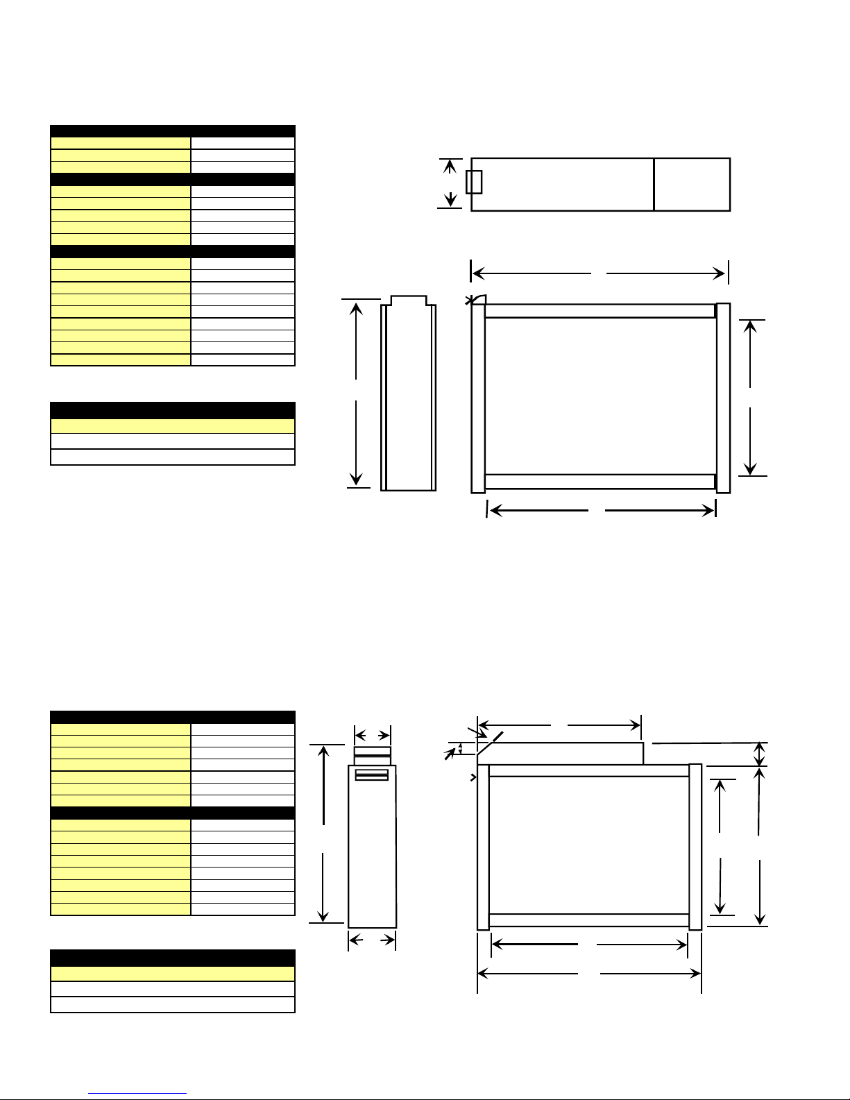
Floor Base
Part Numbers
CFB16
D
F
E
Used On
Models
GCCA045__30
GCCA070__30
Furnace
Gasket
1" Min.
Duct
3/4"
Plenum
F
Floor Base
Floor
3/4"
E
Front View
Used On
Models
GCCA045__30
GCCA070__30
GCCA070__40
GCCA090__40
GCCA090__50
GCCA115__50
A
B
C
Floor Base
Part Numbers
CFB16
CFB20
CFB24
G
ABCDEFG
18-9/16 23-3/4 29 17-1/2 16-1/2 15 1-11/32
Furnac e Front
Plenum
4-7/16"
B
A
Side View
Floor Opening Plenum Size
HJKL
16-1/2 23-3/4 15 18-9/16
20-1/2 23-3/4 19 18-9/16
24-1/2 23-3/4 23 18-9/16
All dimension are in inches.
2"
3/4"
CFB20
CFB24
GCCA070__40
GCCA090__40
GCCA090__50
GCCA115__50
18-9/16 23-3/4 29 21-1/2 20-1/2 19 1-11/32
18-9/16 23-3/4 29 25-1/2 24-1/2 23 1-11/32
COUNTERFLOW FLOOR BASE
23.567
4.500
EFR01 EXTERNAL FILTER RACK KIT
Used On Models
GUCA
GCCA
INTERNAL
FILTER
RETAINERS
(80% MODELS
ONLY)
FILTER KIT PLUG FOR
STANDARD ELECTR ICAL INLET
ALTERNATE
ELECTRICAL INLET
LOCATION
(GUCA ONLY)
FRONT
OF UNIT
BASE
OF UNIT
(GUCA ONLY)
All dimension are in inches.
INTERNAL FILTER
RETAINER SCREWS
(80% MODELS ONLY)
UNIT SIDE
PANEL
RETURN AIR
CUTOUT AREA
SLOTS IN FILTER
CLEAR SCREWS
ON UNIT
BLOWER DECK
LOWER EDGE
SCREW
SCREWS
FILTER RACK ASSEMBLY
(FACE FILTER OPENING
TOWARDS FRONT
OF UNIT)
EXTERNAL FILTER RACK KIT
11 Rev. 0
PRODUCT IDENTIFICATION
(
g
(2)
ACCESSORIES
MAC1 SPEC IFICATIONS
CAPACITY
MEDIA SERVICE LI FE
MEDIA LISTING
DIMENSIONS
A
B
C
D 22-5/8
E
RESISTANCE
CFM INCHES W. C.
600 .04
800
1000
1200
1400 .15
1600
1800
2000
All dimensions are in inches.
MEDIA AIR CLEANER
Used On Models
GUCA
GUCA
600-2000CFM
12 MO.NOMINAL
UL CLASS 2
7-1/4
25
22-1/8
17-11/16
.05
.09
.12
.18
.22
.27
A
B
C
E
D
EAC5 SPECIFICATIONS
RATED CAPACITY
MAX. PRESSURE DROP
CELL WEIGHT
UNIT WEIGHT
POWER CONSUMPTION
ELECTRICAL INPUT
ELECTRICAL OUTPUT
DIMENSION S
A
B
C 7-3/16
D
E
F
G 22-1/2
H
EAC5 ELECTRONIC AIR CLEANER
Used On Models
GUCA
GCCA
2000 CFM
.13 in. w.
12 lbs. each
46 lbs.
48 watts maximum
120 V , 60 HZ, 1
3.2 MA @ 6200
4-1/2
24-7/16
20-5/16
20-3/4
17-3/4
All dimensions are in inches.
25
MEDIA AIR CLEANER
3400
. @
B
A
2-1/8"
C
30°
H
E
D
3-1/2"
G
F
12 Rev. 0
ELECTRONIC AIR CLEANER

PRODUCT IDENTIFICATION
g
g
ACCESSORIES
Vertical
(VCVK)
Horizontal
(HCVK)
Connection for
Fresh Air Intake
Pipe to Furnace
Connection for
Vent/Flue Pipe
from Furnace
Pipe to Furnace
Tee
Inside
Combustion
Air Intake Pipe
Outside
Seal Penetration
with Caulking
Wall Thick ne ss
3/4" Minimum
13 3/4" Maximum
HVCK Installation
Concentric Vents Kits HVCK and VCVK
are suitable for use with the following
Amana 90% efficient furnace products:
CONCENTRIC VENT KIT
Used On Models
GUCA
GCCA
This kit is not certified for, and must not
be applied to any furnace not listed in the
above table.
Vent/Flue Termination
with Tee
12" Minimum Above
Grade or Highest
Anticipate Snow Level
Combustion Air
Intake Pipe
Roof Thicknes s
3/4" Minimum
22" Maximum
Interior Section
of Concentric Vent Assembly
Must Be Adequat ely
Secured and Supported
Sanitary Tee
Connection for
Fresh Air Intake
Pipe to Furnace
VCVK Installation
(Tee, Pipe, & 2" to 4" Reducer)
12" Minimum Above
Roof or Highest
Anticipated Snow Level
Outside
Inside
Connection for
Vent/ Flue Pipe
From Furnace
Vent/Flue
Termination
Seal Penetration
with Flashin
and Caulkin
CONCENTRIC VENT CONVERSION KIT
13 Rev. 0

FURNACE SPECIFICATIONS
g
MODEL
Btuh
Input (US) 46,000 69,000 69,000 92,000 92, 000 115,000
Output (US) 42,800 64,400 64,400 86,000 85,300 106,500
Input (CAN) 46,000 69,000 69,000 92,000 90,000 115,000
Output (CAN) 42,800 64,400 64,400 86,000 85,300 106,500
A.F.U.E. 92.0% 92.0% 92.0% 92.0% 92.0% 92.0%
Rated External Static (WC) .20 - .50 .20 - .50 .20 - .50 .20 - .50 .20 - .50 .20 - .50
Temper ature Rise °F 35 - 65 35 - 65 35 - 65 35 - 65 35 - 65 35 - 65
ID Blower Pressure Switch Tr ip Point -0.37 -0.37 -0.37 -0.37 -0.37 -0.37
Front Cover Pressure Switch Trip Point -0.37 -0.37 -0.37 -0.37 -0.37 -0.37
Blower Wheel (D x W)" 11 x 6 11 x 7 11 x 9 11 x 9 11 x 9 11 x 10
Blower Horsepower 1/3 1/2 1/2 1/2 3/4 3/4
Blower Speeds 444444
Max CFM @ 0.5 E.S.P. 1196 1406 1643 1544 2128 2029
Power Supply 115-60-1 115-60-1 115-60-1 115-60-1 115-60-1 115-60-1
Min. Circuit Ampacity (MCA) 9.0 8.9 8.9 8.9 13.8 14.9
Max. Overcurrent Device 15.0 15.0 15.0 15.0 15.0 15.0
Transformer (VA) 40 40 40 40 40 40
Heat Anticipator 0.7 0.7 0.7 0.7 0.7 0.7
Limit Setting °F 150 150 160 150 150 150
Aux. Limit °F . 150 150 150 150 150 160
Fan Delay Timings
On Heating 30 secs. 30 secs. 30 secs. 30 secs. 30 secs. 30 secs.
Off Heating * 90 secs. 90 secs. 90 secs. 90 secs. 90 secs. 90 secs.
On Cooling 5 sec. 5 sec. 5 sec. 5 sec. 5 sec. 5 sec.
Off Cooling 45 secs. 45 secs. 45 secs. 45 secs. 45 secs. 45 secs.
Gas Supply Pressure (Nat/LP) 7" / 11" 7" / 11" 7" / 11" 7" / 11" 7" / 11" 7" / 11"
Manifold Pressure (Nat/LP) 3.5 " / 10" 3.5 " / 10" 3.5 " / 10" 3.5 " / 10" 3.5 " / 10" 3.5 " / 10 "
Orifice Size (Nat/LP) #43 / #55 #43 / #55 #43 / #55 #43 / #55 #43 / #55 #43 / #55
Number of Burners 233445
Vent Connector Diameter 2" 2" 2" 2" 2" 2"
Combust io n Air Connector Diameter 2" 2" 2" 2" 2" 2"
Shipping Weight (lbs.) 131 144 152 166 175 187
GUCA045AX30 GUCA070AX30 GUCA070AX40 GUCA090AX40 GUCA090AX50 GUCA115AX50
* Off Heatin
- This fan del ay timing is adjustabl e (60, 90, 120 or 180 seconds). 90 seconds as shipp ed.
1. These furnaces are manufactured for natural gas operation. Optional LP Conversion Kits are available to convert
to propane gas.
2. When these furnaces are installed at high altitude, the appropriate High Altitude orifice kit must be applied. This is
required due to the natural reduction in the density of both the gas fuel and combustion air as altitude increases. The
kit will provide the proper design certified input rate within the specified altitude range.
3. The total heat loss from the structure as expressed in TOTAL BTU/HR must be calculated by the manufactures
method of in accordance with the "A.S.H.R.A.E. GUIDE" or "MANUAL J-LOAD CALCULATIONS" published by the
AIR CONDITIONING CONTRACTORS OF AMERICA. The total heat loss calculated should be equal to or less
than the heating capacity. Output based on D.O.E. test procedures, steady state efficiency times output.
4. Minimum Circuit Ampacity calculated as: (1.25 x Circulation Blower Amps) + I.D. Blower Amps.
14 Rev. 0

FURNACE SPECIFICATIONS
g
MODEL
Btuh
Input (US) 46,000 69,000 69,000 92,000 92,000 115,000
Output (US) 43,000 65,400 63,300 87,500 86,200 109,100
Input (CAN) 46,000 69,000 69,000 92,000 92,000 115,000
Output (CAN) 43,000 65,400 63,300 87,500 86,200 109,100
A.F.U.E. 92.0% 92.0% 92.0% 92.0% 92.0% 92.0%
Rated External Static (WC) .20 - .50 .20 - .50 .20 - .50 .20 - .50 .20 - .50 .20 - .50
Temperature Rise °F 35 - 65 35 - 65 35 - 65 40 - 70 35 - 65 40 - 70
ID Blower Pressure Switch Trip Point -0.37 -0.37 -0.37 -0.37 -0.37 -0 .37
Front Cover Pressure Switch Trip Point -0.37 -0.37 -0.37 -0.37 -0.37 -0.37
Blower Wheel (D x W)" 11 x 6 11 x 7 11 x 9 11 x 9 11 x 9 11 x 10
Blower Horsepower 1/3 1/2 1/2 1/2 3/4 3/4
Blower Speeds 444444
Max CFM @ 0.5 E.S.P. 1195 1366 1590 1581 1987 1903
Power Supply 115-60-1 115-60-1 115-60-1 115-60-1 115-60-1 115-60-1
Min. Circuit Ampacity (MCA) 9.0 8.9 8.9 8.9 13.8 14.9
Max. Overcurrent Device 15.0 15.0 15.0 15.0 15.0 15.0
Transformer (VA) 40 40 40 40 40 40
Heat Anticipator 0.7 0.7 0.7 0.7 0.7 0.7
Limit Setti ng °F 170 170 170 150 170 155
Aux. Limit °F. 160 160 160 160 170 160
Fan Delay Timings
On Heating 30 secs. 30 secs. 30 secs. 30 secs. 30 secs. 30 secs.
Off Heating * 90 secs. 90 secs. 90 secs. 90 secs. 90 secs. 90 secs.
On Cooling 5 sec. 5 sec. 5 sec. 5 sec. 5 sec. 5 sec.
Off Cooling 45 secs. 45 secs. 45 secs. 45 secs. 45 secs. 45 secs.
Gas Supply Pressure (Nat/LP) 7" / 11" 7" / 11" 7" / 11" 7" / 11" 7" / 11" 7" / 11"
Manifold Pressure (Nat/LP) 3.5 " / 10" 3.5 " / 10" 3.5 " / 10" 3.5 " / 10" 3.5 " / 10" 3.5 " / 10"
Orifice Size (Nat/LP) #43 / #55 #43 / #55 #43 / #55 #43 / #55 #43 / #55 #43 / #55
Number of Burners 233445
Vent Connector Diameter 2" 2" 2" 2" 2" 2"
Combustion Air Connector Diameter 2" 2" 2" 2" 2" 2"
Shipping Weight (lbs.) 132 145 153 167 176 188
GCCA045AX30 GCCA070AX30 GCCA070AX40 GCCA090AX40 GCCA090AX50 GCCA115AX50
* Off Heatin
- This fan delay timing is adjustable (60, 90, 120 or 180 seconds). 90 seconds as shipped.
1. These furnaces are manufactured for natural gas operation. Optional LP Conversion Kits are available to convert
to propane gas.
2. When these furnaces are installed at high altitude, the appropriate High Altitude orifice kit must be applied. This is
required due to the natural reduction in the density of both the gas fuel and combustion air as altitude increases. The
kit will provide the proper design certified input rate within the specified altitude range.
3. The total heat loss from the structure as expressed in TOTAL BTU/HR must be calculated by the manufactures
method of in accordance with the "A.S.H.R.A.E. GUIDE" or "MANUAL J-LOAD CALCULATIONS" published by the
AIR CONDITIONING CONTRACTORS OF AMERICA. The total heat loss calculated should be equal to or less
than the heating capacity. Output based on D.O.E. test procedures, steady state efficiency times output.
4. Minimum Circuit Ampacity calculated as: (1.25 x Circulation Blower Amps) + I.D. Blower Amps.
15 Rev. 0

BLOWER PERFORMANCE SPECIFICATIONS
GUCA Bl ower Performance
Model
Heating Sp eed
()
As Shipped
GUCA045AX30 MED 2.5 113135111435109736106837101939 968907827
(MED-LO) MED-LO 2.0 903 44 896 44 876 45 844 47 807 49 764 706 652
GUCA070AX30 MED 3.0 1489 40 1450 41 1415 42 1370 43 1324 45 1261 1205 1130
(MED-LO) MED-LO 2.5 1251 47 1226 48 1205 49 1173 50 1135 52 1096 1037 975
GUCA70AX40 MED 3.5 1620 37 1597 37 1565 38 1516 39 1462 41 1410 1318 1235
(MED-LO) MED-LO 3.0 1387 43 1369 43 1313 45 1284 46 1224 48 1167 1095 1024
GUCA090AX40 MED 3.5 1624 49 1561 51 1520 52 1461 54 1381 57 1297 1217 1109
Motor
Speed
HIGH 3.0 1322 --- 1298 --- 1278 --- 1243 --- 1196 --- 1137 1074 1000
LOW 1.5 702 56 68 0 58 657 60 624 63 584 --- 542 485 423
HIGH 3.5 1590 37 1550 38 1505 39 1454 41 1406 42 1343 1266 1194
LOW 2.0 1001 59 988 60 969 61 956 62 929 64 902 859 807
HIGH 4.0 1861 --- 1823 --- 1778 --- 1721 --- 1643 36 1581 1500 1387
LOW 2.5 1193 50 1162 51 1118 53 1072 55 1012 59 961 894 836
HIGH 4.0 1821 43 1768 45 1699 46 1624 49 1544 51 1439 1354 1227
Tons AC
at 0.5" 0.1 0.2 0.3 0.4 0.5 0.6 0.7 0.8
ESP CFM RISE CFM RISE CFM RISE CFM RISE CF M RISE CFM CF M CFM
External Static Pr essure (Inches Water Column)
(HIGH) MED-LO 3.0 1395 57 1363 58 1311 60 1258 63 1201 66 1120 1045 957
LOW 2.5 1212 65 1164 --- 1126 --- 1080 --- 1014 --- 957 882 815
HIGH 5.0 2375 --- 2323 --- 2282 35 2217 36 2128 37 2056 1956 1857
GUCA090AX50 MED 4.0 1752 45 1741 45 1729 46 1682 47 1640 48 1591 1534 1454
(MED-HI) MED-LO 3.5 1504 53 1487 53 1469 54 1443 55 1412 56 1380 1318 1228
LOW 3.0 1274 62 1258 63 1253 63 1222 65 1201 --- 1147 1072 972
HIGH 5.0 2359 42 2298 43 2208 45 2117 47 2029 49 1914 1783 1678
GUCA115AX50 MED 4.0 1849 53 1808 55 1757 56 1722 57 1651 60 1595 1507 1403
(HIGH) MED-LO 3.5 1575 63 1556 63 1527 65 1497 --- 1456 --- 1370 1290 1205
LOW 3.0 1370 --- 1348 --- 1313 --- 1278 --- 1254 --- 1180 1114 1029
1. CFM in charts is with filters(s). Filters do not ship with this furnace, but must be provided by the installer. If the furnace
requires two return filters, this chart assumes both filters are installed.
2. All furnaces ship as high speed cooling. Installer must adjust blower speed as needed.
3 For most jobs, about 400 CFM per ton when cooling is desirable.
4. INSTALLATION IS TO BE ADJUSTED TO OBTAIN TEMPERATURE RISE WITHIN THE RANGE SPECIFIED ON
THE RATING PLATE.
5. The chart is for information only. For satisfactory operation, external static pressure must not exceed value shown
on rating plate. The shaded area indicates ranges in excess of maximum external static pressure allowed when
heating.
6 The dashed (----) areas indicate a temperature rise not recommended for this model.
7. The above chart is for U.S. furnaces installed at 0-4000 feet. At higher altitudes, a properly derated unit will have
approximately the same temperature rise at a particular CFM, while the ESP at that CFM will be lower.
16 Rev. 0

BLOWER PERFORMANCE SPECIFICATIONS
GUCA Bl ower Performance
Model
Heating Sp eed
()
As Shipped
GCCA045AX30 MED 2.5 1195 ----- 1179 ----- 1136 35 1092 36 1037 38 988 918 839
(MED-LO) MED-LO 2. 0 979 40 949 42 906 43 862 46 816 48 791 736 66 8
GCCA070AX30 MED 3.0 1385 43 1338 44 1300 45 1245 47 1198 49 1138 1075 1008
(MED-HIGH) MED-LO 2.5 116451113552110553106855102758 982931873
GCCA70AX40 MED 3.5 1674
(MED-LO) MED-LO 3.0 1481 40 1407 42 1352 44 1329 44 1234 48 1157 1076 972
GCCA090AX40 MED 3.5 1654 48 1594 49 1531 51 1485 53 1403 56 1263 1239 1157
Motor
Speed
HIGH 3.0 1327 ----- 1342 ----- 1305 ----- 1251 ----- 1195 ----- 1128 1056 969
LOW 1.5 764 52 73 6 54 703 56 668 59 621 63 589 537 477
HIGH 3.5 1594 37 1541 38 1495 40 1426 41 1366 43 1300 1229 1155
LOW 2.0 982 60 95 7 62 924 64 891 -- --- 859 ----- 819 777 724
HIGH 4.0 1911 ----- 1838 ----- 1762 ----- 1674 35 1590 37 1501 1407 1294
LOW 2.5 1282 46 1234 48 1183 50 1117 53 1047 56 987 906 818
HIGH 4.0 1867 42 1797 44 1730 46 1660 47 1581 50 1498 1403 1316
Tons AC
at 0.5" 0.1 0.2 0.3 0.4 0.5 0.6 0. 7 0.8
ESP CFM RISE CFM RISE CFM RISE CFM RISE CF M RISE CFM CF M CFM
35
External Static Pr essure (Inches Water Column)
1609 37 1551 38 1481 40 1407 42 1329 1234 1157
(HIGH) MED-LO 3.0 1452 54 1407 56 1353 58 1295 61 1225 64 1156 1083 1005
LOW 2.5 1255 63 1206 65 1165 68 1115 ----- 10 56 ----- 997 93 1 849
HIGH 5.0 2313 ----- 2243 35 2171 36 2066 38 1987 40 1889 1785 1655
GCCA090AX50 MED 4.5 1900 41 1862 42 1810 44 1744 45 1674 47 1601 1510 1412
(MED-L0) MED-LO 3.5 1661 47 1615 49 1583 50 1530 52 1480 53 1406 1332 1245
LOW 3.0 1450 54 1415 56 1379 57 1332 59 1284 61 1219 1144 1053
HIGH 5.0 2283 43 2192 45 2108 47 2012 49 1903 52 1829 1727 1636
GCCA115AX50 MED 4.5 1910 52 1860 53 1782 55 1714 57 1658 59 1555 1460 1377
(MED-HI) MED-LO 3.5 1686 58 1644 60 1585 62 1524 65 1460 67 1411 1324 2132
LOW 3.0 1460 67 1410 70 1377 ---- - 1324 ---- - 1288 ----- 1212 1152 1067
1. CFM in charts is with filters(s). Filters do not ship with this furnace, but must be provided by the installer. If the furnace
requires two return filters, this chart assumes both filters are installed.
2. All furnaces ship as high speed cooling. Installer must adjust blower speed as needed.
3 For most jobs, about 400 CFM per ton when cooling is desirable.
4. INSTALLATION IS TO BE ADJUSTED TO OBTAIN TEMPERATURE RISE WITHIN THE RANGE SPECIFIED ON
THE RATING PLATE.
5. The chart is for information only. For satisfactory operation, external static pressure must not exceed value shown
on rating plate. The shaded area indicates ranges in excess of maximum external static pressure allowed when
heating.
6 The dashed (----) areas indicate a temperature rise not recommended for this model.
7. The above chart is for U.S. furnaces installed at 0-4000 feet. At higher altitudes, a properly derated unit will have
approximately the same temperature rise at a particular CFM, while the ESP at that CFM will be lower.
17 Rev. 0

BLOWER PERFORMANCE SPECIFICATIONS
18 Rev. 0

COMBUSTION AND VENTILATION AIR
(DIRECT/NON-DIRECT VENT MODELS)
WARNING
Property damage, bodily injury, or death may occur if
the furnace and any other fuel-burning appliances are
not provided with enough fresh air for proper combustion and ventilation of flue gases. Most homes require
outside air to be supplied into the furnace area.
Improved construction and additional insulation in homes
has reduced the heat loss and made these homes much
tighter around doors and windows so that air infiltration is
minimal. This creates a problem to supply combustion and
ventilation air for gas fired or other fuel burning appliances..
Any use of appliances that pull air out of the house (clothes
dryers, exhaust fans, fireplaces, etc.) increases this problem and appliances could be starving for air.
In addition, these energy saving measures mean that your
home will retain more water vapor and have a higher relative humidity. High humidity, especially during cold weather,
may be damaging to buildings because condensation forms
on windows and inside walls.
AIR REQUIREMENTS
Most homes will require that outside air be supplied to the
furnace area by means of ventilation grilles or ducts connecting directly to the outdoors or spaces open to the outdoors such as attics or crawl spaces. The following information on air for combustion and ventilation is reproduced
from the National Fuel Gas Code NFPA54/ANSIZ223.1 Section 5.3.
5.3.1 General
(a) The provisions of 5.3 apply to gas utilization equipment
installed in buildings and which require air for combustion,
ventilation and dilution of flue gases from within the building. They do not apply to (1) direct vent equipment which is
constructed and installed so that air for combustion is obtained from the outside atmosphere and all flue gases are
discharged to the outside atmosphere, or (2) enclosed furnaces which incorporate an integral total enclosure and use
only outside air for combustion and dilution of flue gases.
(b) Equipment shall be installed in a location in which the
facilities for ventilation permit satisfactory combustion of
gas, proper venting, and the maintenance of ambient temperature at safe limits under normal conditions of use.
Equipment shall be located so as not to interfere with proper
circulation of air. When normal infiltration does not provide
the necessary air, outside air shall be introduced.
(c) In addition to air needed for combustion, process air
shall be provided as required for: cooling of equipment or
material, controlling dew point, heating, drying, oxidation
or dilution, safety exhaust, odor control, and air for compressors.
(d) In addition to air needed for combustion, air shall be
applied for ventilation, including all air required for comfort
and proper working conditions for personnel.
(e) While all forms of building construction cannot be covered in detail, air for combustion, ventilation, and dilution of
flue gases for gas utilization equipment vented by natural
draft normally may be obtained by appliance of one of the
methods covered in 5.3.3 and 5.3.4.
(f) Air requirements for the operation of exhaust fans,
kitchen ventilation systems, clothes dryers, and fireplaces
shall be considered in determining the adequacy of a space
to provide combustion air requirements.
5.3.2 Equipment Located in Unconfined Spaces:
In unconfined spaces (see definition below) in buildings,
infiltration may be adequate to provide air for combustion,
ventilation and dilution of flue gases. However, in buildings
of tight construction (for example, weather stripping, heavily
insulated, caulked, vapor barrier, etc.), additional air may
need to be provided using the methods described in 5.3.3b or 5.3.4.
Unconfined Space. For purposes of this Code, a space
whose volume is not less than 50 cubic feet per 1,000 Btu
per hour of the aggregate input rating of all appliances installed in that space. Rooms communicating directly with
the space in which the appliances are installed, through
openings not furnished with doors, are considered a part of
the unconfined space.
5.3.3 Equipment Located in Confined Spaces:
(a)
All Air from Inside the Building:
be provided with two permanent openings communicating
directly with an additional room(s) of sufficient volume so
that the combined volume of all spaces meets the criteria
for an unconfined space. The total input of all gas utilization equipment installed in the combined space shall be
considered in making this determination. Each opening shall
have a minimum free area of 1 square inch per 1,000 Btu
per hour of the total input rating of all gas utilization equipment in the confined space, but not less than 100 square
inches. One opening shall be within 12 inches of the top
and one within 12 inches of the bottom of the enclosure.
The following drawing illustrates the air opening specifications for equipment located in confined spaces; all air from
inside building.
The confined space shall
19 Rev. 0

COMBUSTION AND VENTILATION AIR
(DIRECT/NON-DIRECT VENT MODELS)
Equipment Located in Confined Spaces; All Air from
Inside Building. See 5.3.3-a
(b)
All Air from Outdoors:
vided with two permanent openings, one commencing within
12 inches of the top and one commencing within 12 inches
of the bottom of the enclosure. The openings shall communicate directly, or by ducts, with the outdoors or spaces
(crawl or attic) that freely communicate with the outdoors.
1. When directly communicating with the outdoors, each
opening shall have a minimum free area of 1 square
inch per 4,000 BTU per hour of total input rating of all
equipment in the enclosure. The following drawing illustrates the air opening specifications for equipment
located in confined spaces; all air from outdoors-inlet
air from ventilated crawl space and outlet air to ventilated attic.
The confined space shall be pro-
2. When communicating with the outdoors through vertical ducts, each opening shall have a minimum free area
of 1 square inch per 4,000 BTU per hour of total input
rating of all equipment in the enclosure. The following
drawing illustrates the air opening specifications for
equipment located in confined spaces; all air from outdoors through ventilated attic.
Equipment Located in Confined Spaces; All Air
from Outdoors Through Ventilated Attic. See
5.3.3-b.
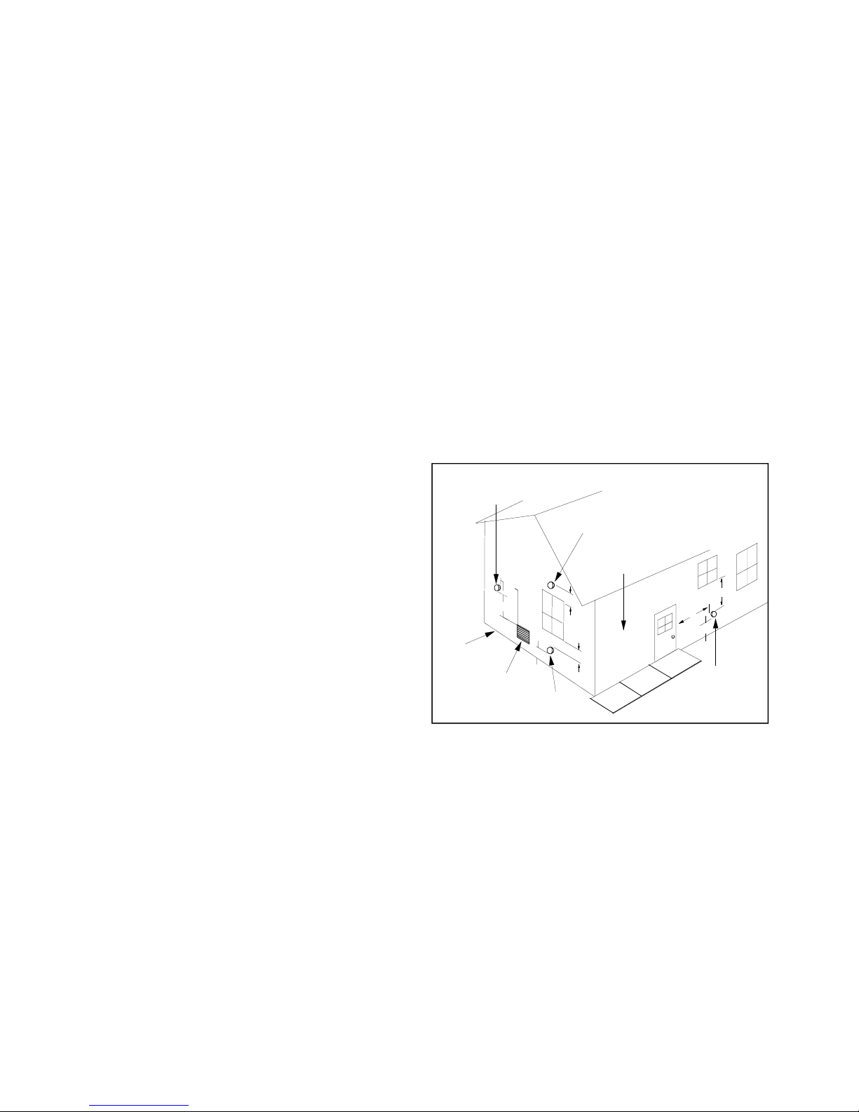
3. When communicating with the outdoors through horizontal ducts, each opening shall have a minimum free
area of 1 square inch per 2,000 BTU per hour of total
input rating of all equipment in the enclosure. The following drawing illustrates the air opening specifications
for equipment located in confined spaces; all air from
outdoors.
Equipment Located in Confined Spaces; All Air from
Outdoors—Inlet Air from Ventilated Crawl Space and
Outlet Air to Ventilated Attic. See 5.3.3-b
20 Rev. 0
*If the appliance room is located against an outside wall and the air openings communicate
directly with the outdoors, each opening shall have a free area of not less than one square inch
per 4,000 BTU per hour of the total input rating of all appliances in the enclosure.
Equipment Located in Confined Spaces; All Air from
Outdoors. See 5.3.3-b.

COMBUSTION AND VENTILATION AIR
(DIRECT/NON-DIRECT VENT MODELS)
4. When ducts are used, they shall be of the same crosssectional area as the free area of the openings to which
they connect. The minimum dimension of rectangular
air ducts shall not be less than 3 inches.
5.3.4 Specially Engineered Installations:
The requirements of 5.3.3 shall not necessarily govern when
special engineering, approved by the authority having jurisdiction, provides an adequate supply of air for combustion, ventilation, and dilution of flue gases.
5.3.5 Louvers and Grilles:
In calculating free area in 5.3.3, consideration shall be given
to the blocking effect of louvers, grilles or screens protecting openings. Screens used shall not be smaller than 1/4
inch mesh. If the area through a design of louver or grille is
known, it should be used in calculating the size of opening
required to provide the free area specified. If the design
and free area is not known, it may be assumed that wood
louvers will have 20-25 percent free area and metal louvers and grilles will have 60-75 percent free area. Louvers
and grilles shall be fixed in the open position or interlocked
with the equipment so that they are opened automatically
during equipment operation.
5.3.6 Special Conditions Created by Mechanical Ex-
hausting or Fireplaces:
Operation of exhaust fans, ventilation systems, clothes dryers, or fireplaces may create conditions requiring special
attention to avoid unsatisfactory operation of installed gas
utilization equipment.
Vent/Flue Pipe and Combustion Air Pipe
General
WARNING
Failure to follow these instructions can result in bodily
injury or death. Carefully read and follow all instructions given in this section.
WARNING
Upon completion of the furnace installation, carefully
inspect the entire flue system both inside and outside
the furnace to assure it is properly sealed. Leaks in the
flue system can result in serious personal injury or
death due to exposure to flue products, including carbon monoxide.
A condensing gas furnace achieves its high level of efficiency by extracting almost all of the heat from the products of combustion and cooling them to the point where
condensation takes place. Because of the relatively low flue
gas temperature and water condensation requirements,
PVC pipe is used as venting material.
This furnace must not be connected to Type B, BW, or L
vent or vent connector, and must not be vented into any
portion of a factory built or masonry chimney except when
used as a pathway for PVC as described later in this section. Never common vent this appliance with another appliance or use a vent which is used by a solid fuel appliance.
Do not use commercially available “no hub connectors” other
than those shipped with this product.
It is the responsibility of the installer to follow the manufacturers’ recommendations and to verify that all vent/flue piping and connectors are compatible with furnace flue products. Additionally, it is the responsibility of the installer to
ensure that all piping and connections possess adequate
structural integrity and support to prevent flue pipe separation, shifting, or sagging during furnace operation.
Dual Certification: Non-Direct/Direct Vent
This furnace is dual certified and may be installed as a nondirect vent (single pipe) or direct vent (dual pipe) appliance.
A
non-direct vent
while a
and a combustion air intake pipe. Refer to the appropriate
section for details concerning piping size, length, number
of elbows, furnace connections, and terminations.
Materials and Joining Methods
direct vent
installation requires only a vent/flue pipe,
installation requires both a vent/flue pipe
WARNING
To avoid fire, explosion, or bodily injury, solvent cements must be kept away from all ignition sources (i.e.,
sparks, open flames, and excessive heat) as they are
combustible liquids. Avoid breathing cement vapors
or contact with skin and/or eyes.
Two- or three-inch nominal diameter PVC Schedule 40 pipe
meeting ASTM D1785, PVC primer meeting ASTM F656,
and PVC solvent cement meeting ASTM D2564 specifications must be used. Fittings must be DWV type fittings
meeting ASTM D2665 and ASTM D3311. Carefully follow
the manufacturer’s instructions for cutting, cleaning, and
solvent cementing of PVC.
As an alternative to PVC pipe, primer, solvent cement, and
fittings, ABS materials which are in compliance with the
following specifications may be used. Two-or-three-inch
ABS Schedule 40 pipe must meet ASTM D1527 and, if
used in Canada, must be CSA listed. Solvent cement for
ABS to ABS joints must meet ASTM D2235 and, if used in
Canada, must be CSA listed. The solvent cement for the
PVC to ABS transition joint must meet ASTM D3138. Fittings must be DWV type fittings meeting ASTM D2661 and
ASTM D3311 and, if used in Canada, must be CSA listed.
Carefully follow the manufacturers’ instructions for cutting,
cleaning, and solvent cementing PVC and/or ABS.
21 Rev. 0
COMBUSTION AND VENTILATION AIR
(DIRECT/NON-DIRECT VENT MODELS)
All 90° elbows must be medium radius (1/4 bend DWV) or
long radius (Long sweep 1/4 bend DWV) types conforming to ASTM D3311. A medium radius (1/4 bend DWV)
elbow measures 3 1/16” minimum from the plane of one
opening to the centerline of the other opening for 2” diameter pipe, and 4 9/16” minimum for 3” pipe.
Proper Vent/Flue and Combustion Air Piping Practices
Adhere to these instructions to ensure safe and proper furnace performance. The length, diameter, and number of
elbows of the vent/flue pipe and combustion air pipe (when
applicable) affects the performance of the furnace and must
be carefully sized. All piping must be installed in accordance
with local codes and these instructions.
Piping must be adequately secured and supported to prohibit sagging, joint separation, and/or detachment from the
furnace. Horizontal runs of vent/flue piping must be supported every three feet and must maintain a 1/4 inch per
foot downward slope, back towards the furnace, to properly return condensate to the furnace’s drain system. Allowances should be made for minor expansion and contraction due to temperature variations. For this reason, particular care must be taken to secure piping when a long run
is followed by a short offset of less than 40 inches.
Precautions should be taken to prevent condensate from
freezing inside the vent/flue pipe and/or at the vent/flue pipe
termination. All vent/flue piping exposed outdoors or in unheated areas must be insulated with 1/2” thick closed cell
foam such as “Armaflex” or “Insultube.” Inspect piping for
leaks prior to installing insulation.
Termination Locations
Note: Refer to
Location Requirements and Considerations
section for combustion air contaminant restrictions.
The following bullets and diagram describe the restrictions
concerning the appropriate location of vent/flue pipe and
combustion air intake pipe (when applicable) terminations.
Refer to
Vent (Dual Pipe) Piping
Non-Direct Vent (Single Pipe) Piping
sections for specific details on ter-
and
Direct
mination construction.
• All terminations must be located at least 12 inches
above ground level or the anticipated snow level.
• Vent terminations must terminate at least 3 feet above
any forced air inlet located within 10 feet.
Note: This provision does not apply to the combustion air
intake termination of a direct vent application.
• The vent termination of a
non-direct vent
application
must terminate at least 4 feet below, 4 feet horizontally from, or 1 foot above any door, window, or gravity air inlet into any building.
• The vent termination of a
direct vent
application must
terminate at least 12 inches from any opening through
which flue gases may enter a building (door, window,
or gravity air inlet).
• The vent termination of vent pipe run vertically through
a roof must terminate at least 12 inches above the
roof line (or the anticipated snow level) and be at least
12 inches from any vertical wall (including any anticipated snow build up).
• A vent termination shall not terminate over public
walkways or over an area where condensate or vapor could create a nuisance or hazard or could be
detrimental to the operation of regulators, relief
valves, or other equipment.
• The combustion air intake termination of a direct vent
application should not terminate in an area which is
frequently dusty or dirty.
Note: In Canada, the Canadian Fuel Gas Code takes precedence over the preceding termination restrictions.
Other Than
Combustion Air
Termination I ntake
Non-Direct Vent
Vent/Flue Termination
No Terminations
Above Walkway
Grade or Highest
Anticipated
Snow Level
10'
3"
Forced Air
Inlet
12"
12"
Vent/Flue Termination
12"
Direct Vent
4'
4'
12"
Non-Direct Vent
Vent/Flue Termination
Vent Termination Clearances
Canadian Venting Requirements
In Canada, venting must conform to the requirements of
the current CAN/CGA-B149 Installation Code. Use only CSA
listed two or three inch diameter PVC or ABS pipe, solvent
cement, and fittings throughout. Carefully follow the manufacturers’ instructions for cutting, cleaning, and solvent cementing PVC and/or ABS.
The vent can be run through an existing unused chimney
provided the space between the vent pipe and the chimney
is insulated and closed with a weather-tight, corrosion-resistant flashing.
The vent shall
not
be located:
• Less than 12 inches above the finished grade line.
22 Rev. 0

COMBUSTION AND VENTILATION AIR
(DIRECT/NON-DIRECT VENT MODELS)
• Less than 36 inches from any building opening or
any gas service regulator. For gas service regulators
in the Province of Ontario, 72 inches.
• Less than 72 inches from the combustion air intake
of another appliance.
• Directly above a gas utility meter or service regulator.
• Over a walkway unless located 84 inches above
grade.
Standard Furnace Connections
It is the responsibility of the installer to ensure that the piping connections to the furnace are secure, airtight, and adequately supported.
As shipped, attachment “couplings” for vent/flue and combustion air intake pipe connections are provided on the
furnace’s top cover (upflow) or basepan (counterflow). To
use the standard connections, field supplied vent/flue pipe
and combustion air intake pipe (when applicable) should
be secured directly to the furnace at these locations.
Vent/Flue Pipe
Vent/flue pipe can be secured to the vent/flue coupling using the rubber coupling and worm gear hose clamps provided with this furnace (See “Standard Connections” figure). The rubber coupling allows separation of the vent/flue
pipe from the furnace during servicing.
Note: Do not use other commercially available “no hub connectors” due to possible material conflicts. The vent/flue
pipe can also be secured using a PVC or ABS elbow or
coupling using the appropriate glue (See
ing Methods
Note: For
section).
non-direct vent
installations, a minimum of one
Materials and Join-
90° elbow must be installed on the combustion air intake
coupling to guard against inadvertent blockage.
Non-Direct Vent Installations
A minimum of one 90° elbow must be installed on the combustion air intake “coupling” to guard against inadvertent
blockage.
(DIRECT VENT ONLY)
90 PVC
ELBOW
(NON-DIRECT VENT)
CUMBUSTION
AIR PIPE
OR
VENT/FLUE
PIPE
RUBBER
COUPLING
WITH WORM
GEAR CLAMPS
PVC
COUPLING
(DIRECT VENT
UPFLOW
90 PVC
ELBOW
(NON-DIRECT VENT)
CUMBUSTION
AIR PIPE
(DIRECT VENT ONLY)
OR
COUNTER FLOW
RUBBER
COUPLINGS
WITH WORM
GEAR CLAMPS
VENT/FLUE
PIPE
Standard Connections
Alternate Furnace Connections
If the standard locations are undesirable for a specific installation, alternate side panel locations are available for
both combustion air inlet and vent/flue pipe connections.
These locations may be of particular benefit to upright upflow
installations requiring additional access to an
"A"
coil, or to
upright counterflow installations requiring additional access
to a filter or electronic air cleaner, or to horizontal installations desiring vent/flue (and combustion air intake) piping
run vertically from the side of the cabinet.
Note: Standard and alternate locations can be combined
(i.e., an installation may use the standard combustion air
intake location but use the alternate vent/flue location or
vice versa), if needed.
CAUTION
Edges of sheet metal holes may be sharp. Use gloves
as a precaution when removing hole plugs.
Combustion Air Pipe
Direct Vent Installations
On
upflow
units secure the combustion air intake pipe directly to the air intake coupling. On
cure the combustion air intake pipe to the air intake coupling using the rubber coupling and worm gear hose clamps
provided with the unit. The counterflow rubber coupling allows service removal of air intake piping internal to the furnace blower compartment. Note: Because of probable material conflicts, do not use other commercially available “no
hub connectors”. The combustion air intake pipe can also
be secured directly to the counterflow unit air intake pipe
coupling.
counterflow
units se-
Alternate Vent/Flue Location
The alternate vent/flue location is the large hole directly in
line with the induced draft blower outlet. To use the alternate vent/flue location refer to the following steps, the “Vent/
Flue Pipe Cuts” figure, and the “Alternate Vent/Flue Location” figure.
Note: Counterflow instructions follow the upflow instructions.
1. Remove and save the four screws securing the vent/
flue coupling to the furnace top panel.
Counterflow
units.
Remove and save the four screws securing the vent/
flue coupling to the furnace basepan. Also remove the
three screws securing the furnace’s internal vent/flue
piping to the blower deck.
23 Rev. 0

COMBUSTION AND VENTILATION AIR
(
)
(
)
R
(DIRECT/NON-DIRECT VENT MODELS)
2.
Upflow
Loosen the worm gear hose clamps on the rubber elbow and detach it from both the induced draft blower
and the vent/flue pipe.
3.
Upflow
Remove the vent/flue pipe from the furnace.
4. Cut the vent/ flue pipe at the elbow nearest the coupling
end of the pipe (See “ Vent/Flue Pipe Cuts” figure). The
section of pipe attached to the coupling will reach
through the side panel to the induced draft blower. Discard unused pipe and elbows.
Counterflow
Cut the vent/flue pipe 3.718 inches from the blower deck
coupling (See “Vent/Flue Pipe Cuts” figure). Save vent/
flue pipe attached to blower deck coupling for use in
the alternate location. Discard remaining pipe and elbows.
COUPLING
ELBOWS
5. Remove plastic plug from alternate vent/flue location.
Relocate and install plug in standard vent/flue location
(top cover).
Counterflow
Remove plastic plug from alternate vent/flue location.
Relocate and install plug in standard vent/flue location
(basepan). Plug remaining hole in blower deck with plastic plug included in the drain kit bag.
6.
Upflow
Insert cut section of vent/flue pipe and coupling into alternate vent/flue location. Using a rubber coupling and
worm gear hose clamps from the drain kit bag, attach
the vent/flue pipe and coupling to the induced draft
blower. Secure the coupling to the cabinet using the
screws removed in step 1 or with field-supplied 3/8” #8
self drilling screws.
24 Rev. 0
UPFLOW
and
Counterflow
and
Counterflow
units.
units.
and
Counterflow
units
.
units
.
4
CUT AT ELBOW
NEAREST COUPLING
CUTPI PE
INSIDE
DECK
FLANG E
OF
COUPLING
BLOWER
COUPLING
Vent/Flue Pipe Cuts
units
.
4
3.718"
BLOWER
FROM
3.718"
DECK
COUNTERFLOW
WARNING
The rubber elbow is not designed to support a load.
When the rubber elbow is mounted externally to the
furnace cabinet, extreme care must be taken to adequately support field-supplied vent/flue piping. As
damage can result in leaks causing bodily injury or
death due to exposure to flue gases, including carbon
monoxide.
7.
Upflow
For upright installations, externally mount the rubber
elbow to the vent/flue coupling using a worm gear hose
clamp. Secure field supplied vent/flue piping to the rubber elbow using a worm gear hose clamp. Note: Use of
the alternate vent/flue location for upright installations,
requires the drain trap be installed on the same side of
the unit as the flue pipe.
8.
Upflow
For
supplied vent/flue pipe directly to the vent/flue coupling
using a PVC or ABS coupling or elbow.
UPFLOW
and
Counterflow
and
Counterflow
horizontal installations
3
REMOVE
PIPE
***
*
M1
*
O
FF
23PC
ON
* *
ID BLOWER WITH
RUBBER COUPLING
SECURE TO
AND HOSE
1
6
REMOVE
2
PIPE
REMOVE
4 SCREWS
ON
23PC
O
*
F
F
M1
***
*
REMOVE
4 SCREWS
AND REL O C A T E
DETATCH RUBBER
ELBOW FROM
ID BLOWER AND
VENT/FLUE
COUNTERFLOW/UPRIGHT
UPFLOW SIMILAR
7
CLAMPS
*
*
123
*
M
PC
ON
*
OF
F
*
* *
UPFLOW/HORIZONTAL
COUNTERFLOW SIMILAR
Alternate Vent/Flue Location
units
.
units
.
, externally secure the field-
1.
COUNTERFLOW
ADDITIONAL PLUG
FROM DRAIN KIT
EXTERNALLY
RUBBER ELBOW
7
SECURE TO
**
ID BLOWER WITH
RUBBER COUPLING
AND HOSE
CLAMPS
SECURE TO
CABINET WITH
* *
ON
23PC
O
*
FF
M1
***
*
6
8
MOUNT
7
SCREWS
3
REMOVE
PIPE
AND REL O C A T E
DETATCH RUBBE
1
REMOVE
4 SCREWS
6
REMOVE
2
ELBOW FROM
ID BLOWER AND
VENT/FLUE
PIPE
 Loading...