


Altronix NETWAYSP8B, NETWAYSP8PL, NETWAYSP8WP, NETWAYSP8WPN, NETWAYSP8WPX Installation Guide
...
Embedded
™
8-Port Ethernet over Fiber PoE+ Hardened Switches
Installation Guide
Models include:
NetWaySP8WP
-Includes Fiber Optic SFP 1G Link, 8-port PoE+ switch and power supply.
-NEMA4/4X, IP66 rated Outdoor enclosure.
NetWaySP8WPX
-Includes Fiber Optic SFP 1G Link, 8-port PoE+ switch and power supply.
-NEMA4/4X, IP66 rated Outdoor enclosure.
-Accommodates up to four (4) 12VDC/4AH batteries.
NetWaySP8X
-Includes Fiber Optic SFP 1G Link, 8-port PoE+ switch and power supply.
-NEMA1 rated Indoor enclosure.
NetWaySP8WPN
-Includes Fiber Optic SFP 1G Link and 8-port PoE+ switch
(uses external power supply).
-NEMA4/4X, IP66 rated Outdoor enclosure.
NetWaySP8PL
-Includes Fiber Optic SFP 1G Link, 8-port PoE+ switch and power supply.
-Backplane version.
NetWaySP8B
-Fiber Optic SFP 1G Link and 8-port PoE+ switch
-Board only.
I.T.E. 43KC
DOC#: NetWaySP8 Rev. 032117 |
More than just power.TM |

Overview:
Altronix NetWay Indoor/Outdoor Ethernet over Fiber PoE Hardened Switches provide two (2) 1Gb SFP ports and eight (8) PoE+ (30W) ports or up to two (2) Hi-PoE (60W) ports, passing data and power to PoE/PoE+ compliant devices. Cameras/edge devices may be located up to 100m from the unit. Features also include an integral battery charger for applications requiring backup and embedded LINQ Technology to monitor, control, and report power and diagnostics from anywhere.
Features:
Input:
•115VAC, 60 Hz, 2.5A or 230VAC, 50/60 Hz, 1.3A. NetWaySP8B/NetWaySP8WPN:
48-55V UL Listed ITE power supply (up to 120W)
Power Output:
•Eight (8) ports PoE+ (30W) or up to two (2) Hi-PoE (60W) ports.
•IEEE 802.3at (30W) and IEEE 802.3af (15W) compliant.
•115W total power.
•Integral surge protection.
Fiber Port:
•Two (2) Gigabit SFP ports.
•Use with SFP module 1000Base-X (1Gb), compliant to Class 1 laser product (not included).
Ethernet Ports:
•Six (6) 10/100 Mbps and
two (2) 10/100/1000 Mbps ports.
•Connectivity: RJ45, auto-crossover.
•Wire type: 4-pair CAT5 or better structured cable.
•Distance: up to 100m.
•Speed: 10/100/1000 Mbps, half/full duplex, auto negotiation.
Battery Backup:
•Built-in charger for sealed lead acid or gel type batteries.
•Automatic switch over to stand-by battery when AC fails.
LEDs:
•Individual PoE On LEDs for each port.
•Individual IP Link status, 10/100Base-T/active
LEDs for each port.
•ALOS LED indicates fiber connection for SFP port.
•Heartbeat LED indicates proper operation of the unit.
Environmental:
•Refer to Technical Specifications Chart on page 4 for Environmental Conditions.
Applications:
• Provides PoE / PoE+ / Hi-PoE for cameras/devices.
LINQ Technology:
•Remote network management allows for camera/ device reset and monitoring.
•Provides local and/or remote access to critical information via LAN/WAN.
•Email and Windows Dashboard Alert notifications report real-time diagnostics.
•Event log tracks history.
Accessories:
NetWaySP1A
•Ethernet over Fiber Media Converter/Repeater - for applications requiring an additional SFP (Fiber) port (Fig. 3, pg. 6).
Mechanical:
NetWaySP8WP
•NEMA4/4X, IP66 Rated enclosure for outdoor use.
•Dimensions (H x W x D approx.): 13.31” x 11.31” x 5.59” (338.1mm x 287.3mm x 142mm).
NetWaySP8WPN
•NEMA4/4X, IP66 Rated enclosure for outdoor use.
•Dimensions (H x W x D approx.): 13.31” x 11.31” x 5.59” (338.1mm x 287.3mm x 142mm).
NetWaySP8WPX
•NEMA4/4X, IP66 Rated enclosure for outdoor use.
•Accommodates four (4) 12VDC/4AH batteries (48V of backup).
•Dimensions (H x W x D approx.): 17.375” x 12” x 6.5”
(441.3mm x 304.8mm x 165.1mm).
NetWaySP8X
•Dimensions (H x W x D approx.):
13.5” x 13” x 3.25” (342.9mm x 330.2mm x 83mm).
NetWaySP8PL
•Dimensions (H x W x D approx.): 10.75” x 8.875” x 2.375” (273.1mm x 225.4mm x 60.3mm).
NetWaySP8B
•Dimensions (L x W x D approx.): 5.625” x 4.5” x 0.625”
(158.8mm x 142.9mm x 15.9mm).
Agency Listings:
•UL/cUL Listed for Information Technology Equipment (UL 60950-1), Information Technology Equipment to Be Installed Outdoors (UL 60950-22).
•CE approved.
- 2 - |
NetWaySP4 Series |
Installation Instructions:
Wiring methods shall be in accordance with the National Electrical Code/NFPA 70/ANSI, and with all local codes and authorities having jurisdiction. All units should be installed by a trained service personnel.
NetWaySP8WP/SP8WPN/SP8WPX Enclosure Mounting and Installation:
1.Remove backplane from enclosure prior to drilling. Do not discard hardware.
Note: Make sure that hardware will not interfere with components of the circuit board.
2.Mark and drill desired inlets on the enclosure to facilitate wiring. Maximum NEMA type 4X rated fittings to be used are 0.5”. Follow manufacturer’s specifications for the appropriate size opening.
Note: Inlets for conduit fittings should only be made on the bottom of the enclosure.
UL Listed NEMA type 4X rated conduit connector/hubs shall be used for the appropriate size inlets.
3.Clean out the inside of enclosure before remounting circuit board.
4.Mounting NEMA4/4X rated enclosure (Enclosure Dimensions, pgs. 11-12):
Wall mount: Mount unit in desired location. Mark and drill holes to line up with the top and bottom holes of the enclosure flange. Secure enclosure with appropriate fasteners (e. g. screws and anchors; bolts and locking nuts, etc.) that are compatible with mounting surface and are of sufficient length/construction to ensure a secure mount (Fig. 5, pg. 8).
Pole Mount: Refer to Figs. 6 - 10, pg. 8.
NetWaySP8WPX only: In order to properly mount NetWaySP8WPX on a pole using Altronix PMK1, additional holes need to be drilled in the enclosure’s flanges, so the distance between those holes is 10”.
5.Mount backplane in enclosure with hardware.
6.To facilitate wire entry utilize weather-tight NEMA rated connectors (supplied), bushings, and cable.
NetWaySP8X Enclosure Mounting and Installation:
1.Mount unit in the desired location. Mark and predrill holes in the wall to line up with the top two keyholes in the enclosure. Install two (2) upper fasteners and screws in the wall with the screw heads protruding. Place the enclosure’s upper keyholes over the two (2) upper screws; level and secure. Mark the position of the lower two (2) holes. Remove the enclosure. Drill the lower holes and install two fasteners. Place the enclosure’s upper keyholes over the two (2) upper screws. Install the two (2) lower screws and make sure to tighten all screws (Enclosure Dimensions, pg. 9). Secure enclosure to earth ground.
NetWaySP8B/SP8PL Mounting and Installation:
1.Mount board/backplane in the desired location/enclosure with hardware supplied.
2.NetWaySP8B: Connect 56VDC/120W max power source to terminal marked [+] and [–].
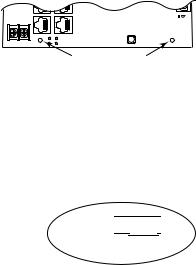
Note: For proper earth ground connections on NetWaySP8B fasten metal standoffs (provided) to threaded studs at indicated board mounting holes (shown on the right).
This is recommended for better environmental immunity.
NetWaySP8B |
|
|
|||
|
PORT 7 |
PoE5 |
PoE6 |
PORT 8 |
Factory Reset |
|
|
||||
+ 48VInput:-56VDC |
-- |
PoE7 |
PoE8 |
|
|
|
|
|
|
||
Metal Standoffs
Installation:
1.For NetWaySP8WP, NetWaySP8WPX, NetWaySP8X, and NetWaySP8PL:
Before powering unit, set input voltage selection switch to proper Input Voltage position (Fig. 3a, pg. 6). Units are factory set for 115VAC.
2.Secure cabinet to earth ground. Connect AC power from overcurrent protective device circuit breaker
(20A @ 115VAC, 60Hz, 16A @ 230VAC, 50/60Hz) to the terminals marked [L, N] on power supply board (Fig. 3, pg. 6). Use 14AWG or larger for all power connections (Battery, DC output, AC input).
Connect ground lug  to earth or green branch wire (12AWG min.).
Note: For NetWaySP8WPN use external 48-55V UL Listed ITE power supply, carefully observing correct polarity (Fig. 4, pg. 7). Keep power-limited wiring separate from non power-limited
wiring by utilizing separate knockouts/inlets.
Minimum 0.25” spacing must be provided. CAUTION: Do not touch exposed metal parts.
Shut branch circuit power before installing or servicing equipment. There are no user serviceable parts inside.
Refer installation and servicing to qualified service personnel.
3. Port Configurations (Fig. 1, pg. 3; Fig. 3b, pg. 6):
Fig. 1
PORT 2 


 30W 60W
|
Jumper |
|
|
|
Structured Cable Ports |
|
|
|
|||
Jumper |
Position |
1 |
2 |
3 |
|
4 |
5 |
|
6 |
7 |
8 |
PORT 4 |
30W |
30W and |
30W and |
30W and |
|
30W and |
----- |
|
----- |
----- |
----- |
Data |
Data |
Data |
|
Data |
|
||||||
|
|
|
|
|
|
|
|
||||
PORT 6 |
30W |
----- |
----- |
----- |
|
----- |
30W and |
|
30W and |
30W and |
30W and |
|
Data |
|
Data |
Data |
Data |
||||||
|
|
|
|
|
|
|
|
||||
PORT 4 |
60W |
Data |
Data |
Data |
|
60W and |
----- |
|
----- |
----- |
----- |
Only |
Only |
Only |
|
Data |
|
||||||
|
|
|
|
|
|
|
|
||||
PORT 6 |
60W |
----- |
----- |
----- |
|
----- |
Data |
|
60W and |
Data |
Data |
|
Only |
|
Data |
Only |
Only |
||||||
|
|
|
|
|
|
|
|
||||
NetWaySP4 Series |
- 3 - |

4.Connect structured cables from port marked [Port 1] to [Port 8] on NetWay unit to PoE-compliant cameras/ edge devices (Fig. 3, pg. 6). Note: All interconnected devices must be UL Listed.
5.Insert SFP module into port(s) marked [SFP], then connect cable to the SFP module on NetWaySP8B to the corresponding input of an SFP switch (Fig. 3, pg. 6).
6.Battery Backup (if desired): Connect four (4) 12VDC batteries wired in series to terminals marked [+ BAT –] (Fig. 3, pg. 6), carefully observing polarity.
When use of stand-by batteries is desired, they must be lead acid or gel type.
Note: When batteries are not used, a loss of AC will result in the loss of output voltage.
7.Please ensure that the cover is secured with:
Key lock and screws for NetWaySP8X, security bolt for NetWaySP8WP, NetWaySP8WPN and
NetWaySP8WPX.
Recommended Altronix SFP Modules:
Altronix P1MM and P1SM10 are hot-pluggable SFP fiber transceiver modules and are readily usable with all Altronix Spectrum fiber optic equipment for 1Gb transmission rates.
P1MM - For use with Multi-Mode Fiber for distances up to 550m. P1SM10 - For use with Single-Mode Fiber for distances up to 10km.
|
Technical Specifications: |
|
|||
|
|
|
|
|
|
Parameter |
Description |
|
|
|
|
Number of Ports |
Eight (8) ports PoE+ (30W) or up to two (2) Hi-PoE (60W) ports. |
||||
Two (2) Gigabit SFP Ports. |
|
|
|
||
|
|
|
|
||
Input Power |
115VAC, 60Hz, 2.5A or 230VAC, 50/60Hz, 1.3A. |
|
|||
Requirements |
NetWaySP8B/NetWaySP8WPN: 48-55V UL Listed ITE power supply |
||||
|
Operating Ambient Temperature: |
|
|
|
|
|
NetWaySP8WP/NetWaySP8WPX: |
60W: -40ºC to 75ºC (-40ºF to 167ºF); |
|||
|
|
|
|
75W: -40ºC to 70ºC (-40ºF to 158ºF); |
|
|
|
|
|
100W: -40ºC to 55ºC (-40ºF to 131ºF); |
|
|
|
|
|
115W: -40ºC to 45ºC (-40ºF to 113ºF). |
|
Environmental |
NetWaySP8X: |
|
115W: -40ºC to 50ºC (-40ºF to 122ºF). |
||
Conditions |
|
||||
|
|
|
|
|
|
|
NetWaySP8B/NetWaySP8WPN: |
115W: -40ºC to 75ºC (-40ºF to 167ºF). |
|||
|
Relative Humidity: 85%, +/- 5% |
|
|
|
|
|
Storage Temperature: -40ºC to 85ºC (-40ºF to 185ºF). |
|
|||
|
Operating Altitude: -304.8 to 2,000m. |
|
|
||
|
Model |
|
Product Weight |
Shipping Weight |
|
|
NetWaySP8WP |
|
10.72 lbs. (4.86 kg) |
12.1 lbs. (5.49 kg) |
|
Weights (approx.) |
NetWaySP8WPN |
|
7.9 lbs. (3.58 kg) |
10.2 lbs. (4.63 kg) |
|
NetWaySP8WPX |
|
15 lbs. (6.8 kg) |
17.5 lbs. (7.9kg) |
||
|
NetWaySP8X |
|
6.85 lbs. (3.11 kg) |
7.75 lbs. (3.51 kg) |
|
|
NetWaySP8PL |
|
2.8 lbs. (1.27 kg) |
4.2 lbs. (1.9 kg) |
|
|
NetWaySP8B |
|
0.45 lbs. (0.2 kg) |
1 lbs. (0.45 kg) |
|
|
|
|
|
|
|
Configuring Units for Network Connection
Please be sure to visit altronix.com for latest firmware and installation instructions
Factory Default Settings
• |
IP Address: |
192.168.168.168 |
• |
User Name: |
admin |
• |
Password: |
admin |
1.Set the static IP address for the laptop to be used for programming to the same network IP address as the NetwaySP8. The default address of the NetwaySP8 is 192.168.168.168, E.I. 192.168.168.200.
2.Connect one end of the network cable to the network jack on the NetwaySP8 and the other to the network connection of the laptop.
- 4 - |
NetWaySP4 Series |
 Loading...