

Page 1

HyperTransport MegaCore Function
User Guide
c
The IP described in this document is scheduled for product obsolescence and
discontinued support as described in PDN0906. Therefore, Altera® does not
recommend use of this IP in new designs. For more information about Altera’s
current IP offering, refer to Altera’s Intellectual Property website.
101 Innovation Drive
San Jose, CA 95134
www.altera.com
MegaCore Version: 9.1
Document Date: November 2009
Page 2

Copyright © 2009 Altera Corporation. All rights reserved. Altera, The Programmable Solutions Company, the stylized Altera logo, specific device designations, and all other
words and logos that are identified as trademarks and/or service marks are, unless noted otherwise, the trademarks and service marks of Altera Corporation in the U.S. and other
countries. All other product or service names are the property of their respective holders. Altera products are protected under numerous U.S. and foreign patents and pending applications, maskwork rights, and copyrights. Altera warrants performance of its semiconductor products to current specifications in accordance with Altera's standard warranty,
but reserves the right to make changes to any products and services at any time without notice. Altera assumes no responsibility or liability arising out of the application or use of
any information, product, or service described herein except as expressly agreed to in writing by Altera Corporation. Altera customers are advised to obtain the latest version of
device specifications before relying on any published information and before placing orders for products or services
.
UG-MCHYPRTRNS-1.12
Page 3

Contents
Chapter 1. About this MegaCore Function
Release Information . . . . . . . . . . . . . . . . . . . . . . . . . . . . . . . . . . . . . . . . . . . . . . . . . . . . . . . . . . . . . . . . . . . . . 1–1
Device Family Support . . . . . . . . . . . . . . . . . . . . . . . . . . . . . . . . . . . . . . . . . . . . . . . . . . . . . . . . . . . . . . . . . . . 1–1
Introduction . . . . . . . . . . . . . . . . . . . . . . . . . . . . . . . . . . . . . . . . . . . . . . . . . . . . . . . . . . . . . . . . . . . . . . . . . . . . 1–2
Features . . . . . . . . . . . . . . . . . . . . . . . . . . . . . . . . . . . . . . . . . . . . . . . . . . . . . . . . . . . . . . . . . . . . . . . . . . . . . . . . 1–2
OpenCore Plus Evaluation . . . . . . . . . . . . . . . . . . . . . . . . . . . . . . . . . . . . . . . . . . . . . . . . . . . . . . . . . . . . . 1–3
Performance . . . . . . . . . . . . . . . . . . . . . . . . . . . . . . . . . . . . . . . . . . . . . . . . . . . . . . . . . . . . . . . . . . . . . . . . . . . . 1–3
Chapter 2. Getting Started
Design Flow . . . . . . . . . . . . . . . . . . . . . . . . . . . . . . . . . . . . . . . . . . . . . . . . . . . . . . . . . . . . . . . . . . . . . . . . . . . . 2–1
MegaCore Function Walkthrough . . . . . . . . . . . . . . . . . . . . . . . . . . . . . . . . . . . . . . . . . . . . . . . . . . . . . . . . . 2–2
Create a New Quartus II Project . . . . . . . . . . . . . . . . . . . . . . . . . . . . . . . . . . . . . . . . . . . . . . . . . . . . . . . . . 2–2
Launch the MegaWizard Plug-in Manager . . . . . . . . . . . . . . . . . . . . . . . . . . . . . . . . . . . . . . . . . . . . . . . 2–3
Step 1: Parameterize . . . . . . . . . . . . . . . . . . . . . . . . . . . . . . . . . . . . . . . . . . . . . . . . . . . . . . . . . . . . . . . . . . . 2–5
Step 2: Set Up Simulation . . . . . . . . . . . . . . . . . . . . . . . . . . . . . . . . . . . . . . . . . . . . . . . . . . . . . . . . . . . . . . 2–9
Step 3: Generate . . . . . . . . . . . . . . . . . . . . . . . . . . . . . . . . . . . . . . . . . . . . . . . . . . . . . . . . . . . . . . . . . . . . . 2–11
Simulate the Design . . . . . . . . . . . . . . . . . . . . . . . . . . . . . . . . . . . . . . . . . . . . . . . . . . . . . . . . . . . . . . . . . . . . 2–13
Compile the Design . . . . . . . . . . . . . . . . . . . . . . . . . . . . . . . . . . . . . . . . . . . . . . . . . . . . . . . . . . . . . . . . . . . . . 2–13
Program a Device . . . . . . . . . . . . . . . . . . . . . . . . . . . . . . . . . . . . . . . . . . . . . . . . . . . . . . . . . . . . . . . . . . . . . . 2–14
Set Up Licensing . . . . . . . . . . . . . . . . . . . . . . . . . . . . . . . . . . . . . . . . . . . . . . . . . . . . . . . . . . . . . . . . . . . . . . . 2–15
Append the License to Your license.dat File . . . . . . . . . . . . . . . . . . . . . . . . . . . . . . . . . . . . . . . . . . . . . 2–15
Specify the License File in the Quartus II Software . . . . . . . . . . . . . . . . . . . . . . . . . . . . . . . . . . . . . . . . 2–15
Example Simulation and Compilation . . . . . . . . . . . . . . . . . . . . . . . . . . . . . . . . . . . . . . . . . . . . . . . . . . . . . 2–16
Example Quartus II Project . . . . . . . . . . . . . . . . . . . . . . . . . . . . . . . . . . . . . . . . . . . . . . . . . . . . . . . . . . . . 2–16
Example Simulation with Test Vectors . . . . . . . . . . . . . . . . . . . . . . . . . . . . . . . . . . . . . . . . . . . . . . . . . . 2–16
Chapter 3. Specifications
HyperTransport Technology Overview . . . . . . . . . . . . . . . . . . . . . . . . . . . . . . . . . . . . . . . . . . . . . . . . . . . . . 3–1
HT Systems . . . . . . . . . . . . . . . . . . . . . . . . . . . . . . . . . . . . . . . . . . . . . . . . . . . . . . . . . . . . . . . . . . . . . . . . . . 3–2
HT Flow Control . . . . . . . . . . . . . . . . . . . . . . . . . . . . . . . . . . . . . . . . . . . . . . . . . . . . . . . . . . . . . . . . . . . . . . 3–3
HyperTransport MegaCore Function Specification . . . . . . . . . . . . . . . . . . . . . . . . . . . . . . . . . . . . . . . . . . . 3–3
Physical Interface . . . . . . . . . . . . . . . . . . . . . . . . . . . . . . . . . . . . . . . . . . . . . . . . . . . . . . . . . . . . . . . . . . . . . 3–4
Synchronization and Alignment . . . . . . . . . . . . . . . . . . . . . . . . . . . . . . . . . . . . . . . . . . . . . . . . . . . . . . . . 3–4
Protocol Interface . . . . . . . . . . . . . . . . . . . . . . . . . . . . . . . . . . . . . . . . . . . . . . . . . . . . . . . . . . . . . . . . . . . . . 3–5
Clocking Options . . . . . . . . . . . . . . . . . . . . . . . . . . . . . . . . . . . . . . . . . . . . . . . . . . . . . . . . . . . . . . . . . . . . . 3–7
HyperTransport MegaCore Function Parameters and HT Link Performance . . . . . . . . . . . . . . . . . 3–10
Signals . . . . . . . . . . . . . . . . . . . . . . . . . . . . . . . . . . . . . . . . . . . . . . . . . . . . . . . . . . . . . . . . . . . . . . . . . . . . . 3–14
CSR Module . . . . . . . . . . . . . . . . . . . . . . . . . . . . . . . . . . . . . . . . . . . . . . . . . . . . . . . . . . . . . . . . . . . . . . . . . 3–31
OpenCore Plus Time-Out Behavior . . . . . . . . . . . . . . . . . . . . . . . . . . . . . . . . . . . . . . . . . . . . . . . . . . . . . 3–40
Appendix A. Parameters
Introduction . . . . . . . . . . . . . . . . . . . . . . . . . . . . . . . . . . . . . . . . . . . . . . . . . . . . . . . . . . . . . . . . . . . . . . . . . . . A–1
Parameter Lists . . . . . . . . . . . . . . . . . . . . . . . . . . . . . . . . . . . . . . . . . . . . . . . . . . . . . . . . . . . . . . . . . . . . . . . . A–1
Device Family and Read Only Registers . . . . . . . . . . . . . . . . . . . . . . . . . . . . . . . . . . . . . . . . . . . . . . . . . A–1
Base Address Registers . . . . . . . . . . . . . . . . . . . . . . . . . . . . . . . . . . . . . . . . . . . . . . . . . . . . . . . . . . . . . . . A–2
Clocking Options . . . . . . . . . . . . . . . . . . . . . . . . . . . . . . . . . . . . . . . . . . . . . . . . . . . . . . . . . . . . . . . . . . . . A–3
Advanced Settings . . . . . . . . . . . . . . . . . . . . . . . . . . . . . . . . . . . . . . . . . . . . . . . . . . . . . . . . . . . . . . . . . . . A–3
© November 2009 Altera Corporation HyperTransport MegaCore Function User Guide
Page 4

iv Contents
Appendix B. Stratix Device Pin Assignments
Introduction . . . . . . . . . . . . . . . . . . . . . . . . . . . . . . . . . . . . . . . . . . . . . . . . . . . . . . . . . . . . . . . . . . . . . . . . . . . B–1
Guidelines . . . . . . . . . . . . . . . . . . . . . . . . . . . . . . . . . . . . . . . . . . . . . . . . . . . . . . . . . . . . . . . . . . . . . . . . . . . . . B–1
Appendix C. Example Design
General Description . . . . . . . . . . . . . . . . . . . . . . . . . . . . . . . . . . . . . . . . . . . . . . . . . . . . . . . . . . . . . . . . . . . . C–1
Additional Information
Revision History . . . . . . . . . . . . . . . . . . . . . . . . . . . . . . . . . . . . . . . . . . . . . . . . . . . . . . . . . . . . . . . . . . . . . Info–1
How to Contact Altera . . . . . . . . . . . . . . . . . . . . . . . . . . . . . . . . . . . . . . . . . . . . . . . . . . . . . . . . . . . . . . . . Info–1
Typographic Conventions . . . . . . . . . . . . . . . . . . . . . . . . . . . . . . . . . . . . . . . . . . . . . . . . . . . . . . . . . . . . . Info–2
HyperTransport MegaCore Function User Guide © November 2009 Altera Corporation
Page 5
Release Information
Tab le 1– 1 provides information about this release of the HyperTransport MegaCore®
function.
Table 1–1. HyperTransport MegaCore Function Release Information
Version 9.1
Release Date November 2009
Ordering Code IP-HT
Product ID(s) 0098
Vendor ID(s) 6AF7
®
Altera
previous version of each MegaCore function. Any exceptions to this verification are
reported in the MegaCore IP Library Release Notes and Errata. Altera does not verify
compilation with MegaCore function versions older than one release.
verifies that the current version of the Quartus® II software compiles the
1. About this MegaCore Function
Item Description
c The HyperTransport MegaCore function is scheduled for product obsolescence and
discontinued support as described in PDN0906. Therefore, Altera does not
recommend use of this IP in new designs. For more information about Altera’s current
IP offering, refer to Altera’s Intellectual Property website.
Device Family Support
MegaCore functions provide either full or preliminary support for target Altera
device families:
■ Full support means the MegaCore function meets all functional and timing
requirements for the device family and may be used in production designs.
■ Preliminary support means the MegaCore function meets all functional
requirements, but may still be undergoing timing analysis for the device family; it
may be used in production designs with caution.
Tab le 1– 2 shows the level of support offered by the HyperTransport MegaCore
function for each of the Altera device families.
Table 1–2. Device Family Support
®
Stratix
II Full
Stratix
Stratix II GX Preliminary
Stratix GX Full
Other device families No support
Device Family Support
Full
© November 2009 Altera Corporation HyperTransport MegaCore Function User Guide
Preliminary
Page 6

1–2 Chapter 1: About this MegaCore Function
Introduction
Introduction
The HyperTransport MegaCore function implements high-speed packet transfers
between physical (PHY) and link-layer devices, and is fully compliant with the
HyperTransport I/O Link Specification, Revision 1.03. This MegaCore function allows
designers to interface to a wide range of HyperTransport™ technology (HT) enabled
devices quickly and easily, including network processors, coprocessors, video
chipsets, and ASICs.
Features
The HyperTransport MegaCore function has the following features:
■ 8-bit fully integrated HT end-chain interface
■ Packet-based protocol
■ Dual unidirectional point-to-point links
■ Up to 16 Gigabits per second (Gbps) throughput (8 Gbps in each direction)
■ 200, 300, and 400 MHz DDR links in Stratix and Stratix GX devices
■ 200, 300, 400, and 500 MHz DDR links in Stratix II and Stratix II GX devices
■ Low-swing differential signaling with 100- differential impedance
■ Hardware verified with HyperTransport interfaces on multiple industry standard
processor and bridge devices
■ Fully parameterized MegaCore function allows flexible, easy configuration
■ Fully optimized for the Altera Stratix II, Stratix, Stratix GX, and Stratix II GX
device families
■ Application-side interface uses the Altera Atlantic
■ Manages HT flow control, optimizing performance and ease of use
■ Independent buffering for each HT virtual channel
■ Automatic handling of HT ordering rules
■ Stalling of one virtual channel does not delay other virtual channels (subject to
TM
interface standard
ordering rules)
■ Flexible parameterized buffer sizes, allowing customization depending on
system requirements
■ User interface has independent interfaces for the HT virtual channels, allowing
independent user logic design
■ Cyclic redundancy code (CRC) generation and checking to preserve data integrity
■ Integrated detection and response to common HT error conditions
■ CRC errors
■ End-chain errors
■ Fully integrated HT configuration space includes all required configuration space
registers and HT capabilities list registers
HyperTransport MegaCore Function User Guide © November 2009 Altera Corporation
Preliminary
Page 7

Chapter 1: About this MegaCore Function 1–3
Performance
■ 32-bit and 64-bit support across all base address registers (BARs)
■ Automatically handles all CSR space accesses
■ Verilog HDL and VHDL simulation support
OpenCore Plus Evaluation
With the Altera free OpenCore Plus evaluation feature, you can perform the following
actions:
■ Simulate the behavior of a megafunction (Altera MegaCore function or AMPP
megafunction) within your system
■ Verify the functionality of your design, as well as quickly and easily evaluate its
size and speed
■ Generate time-limited device programming files for designs that include
MegaCore functions
■ Program a device and verify your design in hardware
You only need to purchase a license for the MegaCore function when you are
completely satisfied with its functionality and performance, and want to take your
design to production.
™
f For more information about OpenCore Plus hardware evaluation using the
HyperTransport MegaCore function, refer to “OpenCore Plus Time-Out Behavior” on
page 3–40 and AN 320: OpenCore Plus Evaluation of Megafunctions.
Performance
The HyperTransport MegaCore function uses 20 differential I/O pin pairs and 2
single-ended I/O pins, requiring 42 pins total. Tab le 1– 3 through Table 1–5 show
typical performance and adaptive look-up table (ALUT) or logic element (LE) usage
for the HyperTransport MegaCore function in StratixIIGX, StratixII, Stratix, and
Stratix GX devices respectively, using the Quartus
Tab le 1– 3 shows the maximum supported data rates in megabits per second (Mbps)
by device family and speed grade.
Table 1–3. Maximum Supported HyperTransport Data Rates (Note 1)
Speed Grade
Device Family
-3 -4 -5 -6 -7 -8
Stratix II GX devices 1000 Mbps 1000 Mbps 800 Mbps N/A (2) N/A (2) N/A (2)
Stratix II devices 1000 Mbps 1000 Mbps 800 Mbps N/A (2) N/A (2) N/A (2)
Stratix devices
N/A (2) N/A (2) 800 Mbps 800 Mbps 600 Mbps 400 Mbps
(Flip-Chip packages)
Stratix devices
N/A (2) N/A (2) N/A (2) 600 Mbps 400 Mbps 400 Mbps
(Wire Bond packages)
Stratix GX devices N/A (2) N/A (2) 800 Mbps 800 Mbps 600 Mbps N/A (2)
Notes to Table 1–3:
(1) Rates are per interface bit. Multiply by eight to calculate the uni-directional data rate of an 8-bit interface.
(2) Devices of this speed grade are not offered in this device family.
®
II software version 7.1.
© November 2009 Altera Corporation HyperTransport MegaCore Function User Guide
Preliminary
Page 8

1–4 Chapter 1: About this MegaCore Function
Performance
Tab le 1– 4 shows performance and device utilization for the HyperTransport
MegaCore function in Stratix II and Stratix II GX devices.
Table 1–4. HyperTransport MegaCore Function Performance in Stratix II and Stratix II GX Devices
Parameters
Rx
Posted
Buffers
Rx
Non-Posted
Buffers
Rx
Response
Buffers
Clocking
Option (1) M4K M512
84 4Shared
Combinational
ALUTs
(2)
Logic
Registers
3,500 5,200 12 0 500 125 (4)
Memory
HT Link
(MHz)
f
MAX
(3)
User
Interface
(MHz)
f
MAX
(3)
Rx/Tx/Ref
84 4Shared
3,500 5,200 14 0 500 125 (4)
Ref/Tx
84 4Shared
3,600 5,400 16 0 500 > 150
Rx/Tx
88 8Shared
4,000 6,000 16 0 500 > 150
Rx/Tx
16 8 8 Shared
4,100 6,200 12 0 500 125 (4)
Rx/Tx/Ref
16 8 8 Shared
4,100 6,200 14 0 500 125 (4)
Ref/Tx
16 8 8 Shared
4,200 6,400 16 0 500 > 150
Rx/Tx
Notes to Table 1–4:
(1) Refer to “Clocking Options” on page 3–7 for more information about these options.
(2) Other parameters (BAR configurations, etc.) vary the ALUT and Logic Register utilization numbers by approximately +/- 200.
(3) Figures for -3 speed grade devices only.
(4) When using the Shared Rx/Tx/Ref and Shared Ref/Tx options, the user interface frequency is limited to exactly the HT frequency divided by
four.
Tab le 1– 5 shows performance and device utilization for the HyperTransport
MegaCore function in Stratix and Stratix GX devices.
Table 1–5. HyperTransport MegaCore Function Performance in Stratix and Stratix GX Devices
User Interface f
Rx
Posted
Buffers
Rx
Non-Posted
Buffers
Parameters Utilization HT Link f
Rx
Response
Buffers
Clocking Option
(1)
LEs
(2)
M4K
Blocks
-5 -6 -5 -6
(MHz)
MAX
Speed Grade
(MHz)
8 4 4 Shared Rx/Tx/Ref 7,500 12 400 400 100 (3) 100 (3)
8 4 4 Shared Ref/Tx 7,600 14 400 400 100 (3) 100 (3)
8 4 4 Shared Rx/Tx 7,900 16 400 400 > 125 > 100
8 8 8 Shared Rx/Tx 8,900 16 400 400 > 125 > 100
16 8 8 Shared Rx/Tx/Ref 9,400 12 400 400 100 (3) 100 (3)
16 8 8 Shared Ref/Tx 9,500 14 400 400 100 (3) 100 (3)
16 8 8 Shared Rx/Tx 9,700 16 400 400 > 125 > 100
Notes to Table 1–5:
(1) Refer to “Clocking Options” on page 3–7 for more information about these options.
(2) Other parameters (BAR configurations etc.) vary the LE utilization by approximately +/- 200 LEs.
(3) When using the Shared Rx/Tx/Ref and Shared Ref/Tx options, the user interface frequency is limited to exactly the HT frequency divided by four.
MAX
HyperTransport MegaCore Function User Guide © November 2009 Altera Corporation
Preliminary
Page 9
Design Flow
doc
Contains the documentation for the HyperTransport MegaCore function.
example
Contains the design example for the HyperTransport MegaCore function
lib
Contains encrypted lower-level design files.
ip
Contains the Altera MegaCore IP Library and third-party IP cores.
<path>
Installation directory.
altera
Contains the Altera MegaCore IP Library.
common
Contains shared components.
ht
Contains the HyperTransport HyperTransport MegaCore function files and documentation.
f For system requirements and installation instructions, refer to Altera Software
2. Getting Started
To evaluate the HyperTransport MegaCore function using the OpenCore Plus feature,
include these steps in your design flow:
1. Obtain and install the HyperTransport MegaCore function.
The HyperTransport MegaCore function is part of the MegaCore IP Library, which is
distributed with the Quartus II software and downloadable from the Altera website,
www.altera.com.
Installation and Licensingon the Altera website at
www.altera.com/literature/lit-qts.jsp.
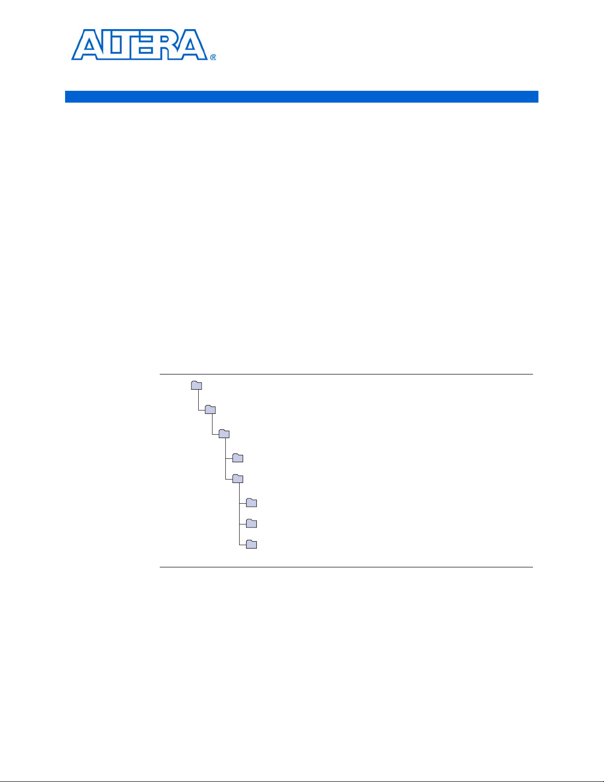
Figure 2–1 shows the directory structure after you install the HyperTransport
MegaCore function, where <path> is the installation directory. The default installation
directory on Windows is C:\altera\<version number>; on Linux it is
/opt/altera<version number>.
Figure 2–1. Directory Structure
2. Create a custom variation of the HyperTransport MegaCore function.
© November 2009 Altera Corporation HyperTransport MegaCore Function User Guide
f For more information about IP functional simulation models, refer to the Simulating
3. Implement the rest of your design using the design entry method of your choice.
4. Use the IP functional simulation model to verify the operation of your design.
Altera IP in Third-Party Simulation Tools chapter in volume 3 of the Quartus II Handbook.
5. Use the Quartus II software to compile your design.
Page 10

2–2 Chapter 2: Getting Started
MegaCore Function Walkthrough
1 You can also generate an OpenCore Plus time-limited programming file,
which you can use to verify the operation of your design in hardware.
6. Purchase a license for the HyperTransport MegaCore function.
After you have purchased a license for the HyperTransport MegaCore function,
follow these additional steps:
1. Set up licensing.
2. Generate a programming file for the Altera device(s) on your board.
3. Program the Altera device(s) with the completed design.
MegaCore Function Walkthrough
This walkthrough explains how to create a custom variation using the Altera
HyperTransport IP Toolbench and the Quartus II software, and simulate the function
using an IP functional simulation model and the ModelSim software. When you are
finished generating your custom variation of the function, you can incorporate it into
your overall project.
1 IP Toolbench allows you to select only legal combinations of parameters, and warns
you of any invalid configurations.
In this walkthrough, you follow these steps:
■ Create a New Quartus II Project
■ Launch the MegaWizard Plug-in Manager
■ Step 1: Parameterize
■ Step 2: Set Up Simulation
■ Step 3: Generate
■ Simulate the Design
1 To generate a wrapper file and IP functional simulation model using default values,
omit the procedure described in “Step 1: Parameterize” on page 2–5.
Create a New Quartus II Project
Create a new Quartus II project with the New Project Wizard, which specifies the
working directory for the project, assigns the project name, and designates the name
of the top-level design entity.
To create a new project, perform the following steps:
1. On the Windows Start menu, select Programs > Altera > Quartus II <version> to
start the Quartus II software. Alternatively, you can use the Quartus II Web Edition
software.
2. In the Quartus II window, on the File menu, click New Project Wizard. If you did
not turn it off previously, the New Project Wizard: Introduction page appears.
3. On the New Project Wizard Introduction page, click Next.
HyperTransport MegaCore Function User Guide © November 2009 Altera Corporation
Page 11

Chapter 2: Getting Started 2–3
MegaCore Function Walkthrough
4. On the New Project Wizard: Directory, Name, Top-Level Entity page, enter the
following information:
a. Specify the working directory for your project. For example, this walkthrough
uses the C:\altera\projects\ht_project directory.
b. Specify the name of the project. This walkthrough uses ht_example for the
project name.
1 The Quartus II software automatically specifies a top-level design entity
that has the same name as the project. This walkthrough assumes that the
names are the same.
5. Click Next to close this page and display the New Project Wizard: Add Files page.
1 When you specify a directory that does not already exist, a message asks if
the specified directory should be created. Click Yes to create the directory.
6. Click Next to close this page and display the New Project Wizard: Family and
Device Settings page.
7. On the New Project Wizard: Family & Device Settings page, perform the
following steps:
a. in the Family list, select the target device family.
b. Under Ta r g e t d e v i c e , turn on Specific device selected in ’Available devices’
list.
c. In the Available devices list, select a device.
8. The remaining pages in the New Project Wizard are optional. Click Finish to
complete the Quartus II project.
You have finished creating your new Quartus II project.
Launch the MegaWizard Plug-in Manager
To launch the MegaWizardTM Plug-in Manager in the Quartus II software, perform the
following steps:
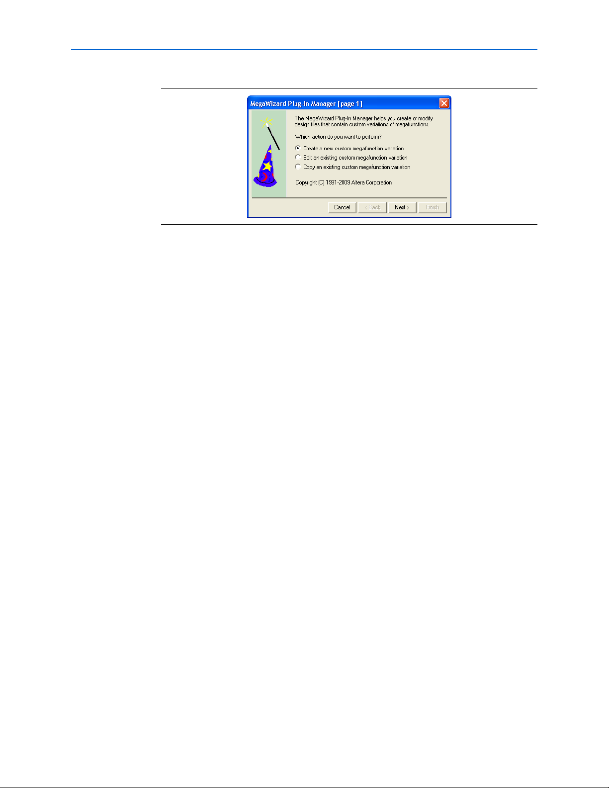
1. On the To ol s menu, click MegaWizard Plug-In Manager. The MegaWizard
Plug-In Manager displays, as shown in Figure 2–2.
1 Refer to Quartus II Help for more information about how to use the
MegaWizard Plug-In Manager.
© November 2009 Altera Corporation HyperTransport MegaCore Function User Guide
Page 12
2–4 Chapter 2: Getting Started
Figure 2–2. MegaWizard Opening Screen
MegaCore Function Walkthrough
2. Choose Create a new custom megafunction variation and click Next.
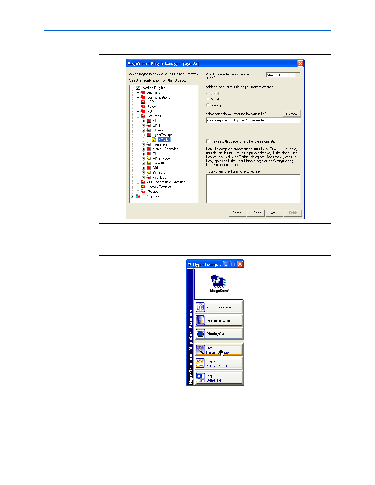
3. Under Interfaces in the HyperTransport folder, click the HT v9.1 component.
4. Choose the device family you want to use for this MegaCore function variation,
for example, Stratix II GX. Your selection should match the device family you
selected in step 7 on page 2–3 when creating the project.
5. Select the output file type for your design; the wizard supports VHDL and Verilog
HDL.
6. The MegaWizard Plug-in Manager shows the project path that you specified in the
New Project Wizard. Append a variation name for the MegaCore function output
files <project path>\<variation name>. For this walkthrough, to create a project that
includes only a single HyperTransport MegaCore function with no additional
logic, define <variation name> to be ht_example to match the project name.
Figure 2–3 shows the wizard after you have made these settings.
HyperTransport MegaCore Function User Guide © November 2009 Altera Corporation
Page 13
Chapter 2: Getting Started 2–5
MegaCore Function Walkthrough
Figure 2–3. Select the MegaCore Function
7. Click Next to launch the IP Toolbench for the HyperTransport MegaCore function.
Figure 2–4. IP Toolbench
Step 1: Parameterize
To parameterize your MegaCore function, follow these steps:
1. In the IP Toolbench, click Step 1: Parameterize, as shown in Figure 2–4. The IP
Toolbench wizard opens to the Device Family & Read-Only Registers tab.
© November 2009 Altera Corporation HyperTransport MegaCore Function User Guide
Page 14
2–6 Chapter 2: Getting Started
MegaCore Function Walkthrough
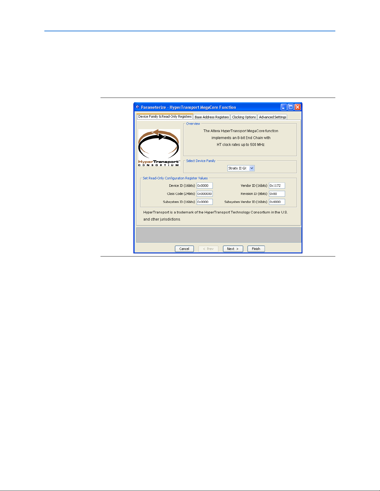
2. Set the target Altera device family and the values for the read-only
HyperTransport configuration registers on the Device Family & Read-Only
Registers tab. For this walkthrough, use the default settings, which are shown in
Figure 2–5. For more information about these parameters, refer to Table A–1 on
page A–1.
Figure 2–5. Parameterize—Device Family and Read-Only Registers
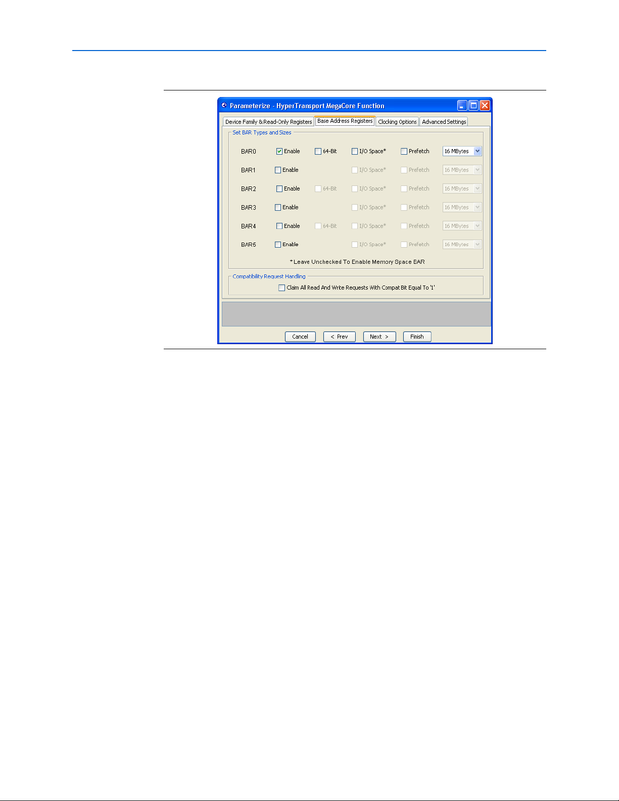
3. Click Next. The Base Address Registers tab appears.
4. On the Base Address Registers tab, configure the HyperTransport BARs that
define the address ranges of memory read and write request packets that your
application claims from the HyperTransport interface. For this walkthrough, use
the default settings, which are shown in Figure 2–6. For more information about
the parameters modified by these settings, refer to Table A–2 on page A–2.
HyperTransport MegaCore Function User Guide © November 2009 Altera Corporation
Page 15
Chapter 2: Getting Started 2–7
MegaCore Function Walkthrough
Figure 2–6. Parameterize—Base Address Registers Tab
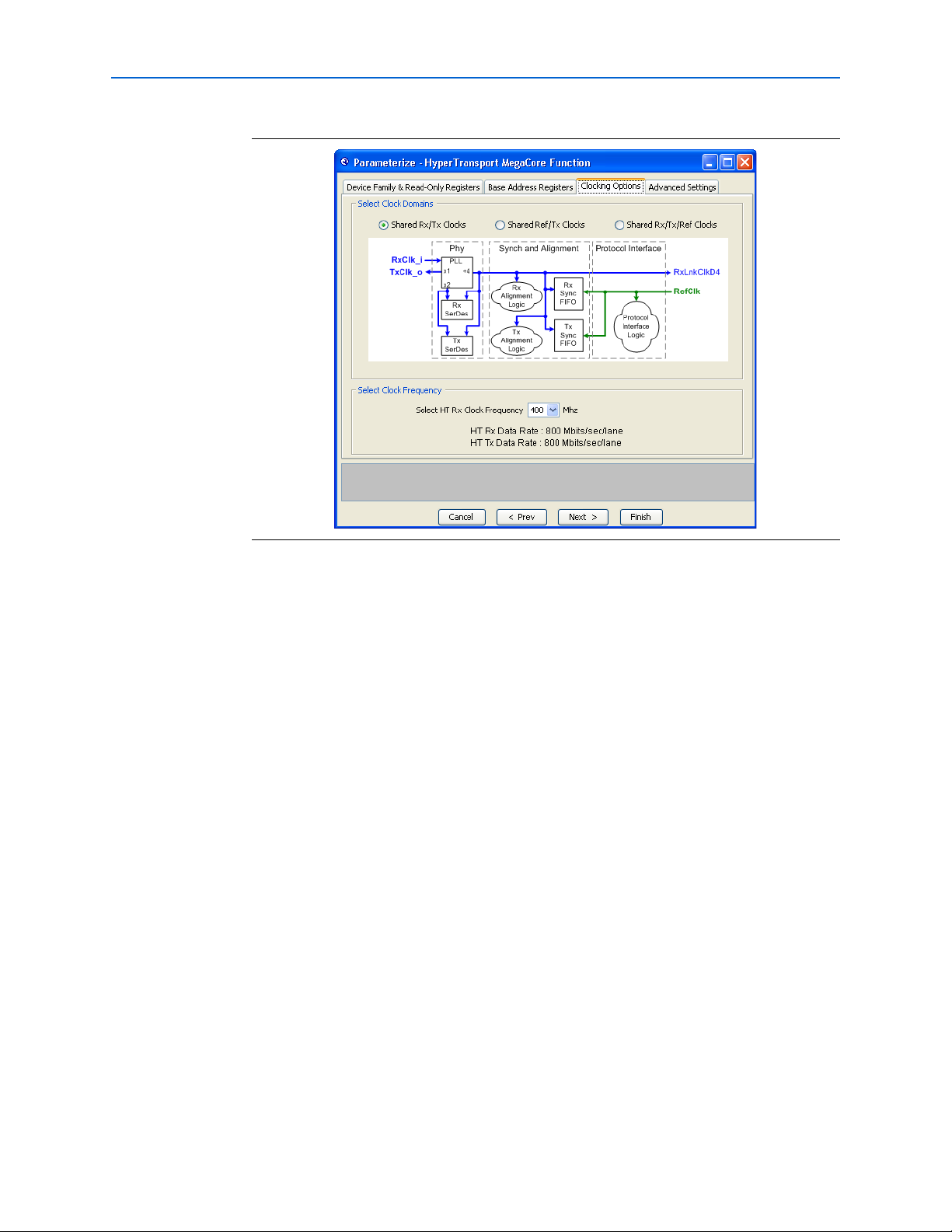
5. Click Next. The Clocking Options tab displays, as shown in Figure 2–7.
6. You set the clocking options for your application on the Clocking Options tab. For
more information about the available options, refer to “Clocking Options” on
page 3–7 and Tabl e A – 3 o n pa ge A–3 . For this walkthrough, use the default
settings, which are shown in Figure 2–7.
1 HyperTransport link clock frequencies of 500 MHz are only supported in
Stratix II and Stratix II GX devices.
© November 2009 Altera Corporation HyperTransport MegaCore Function User Guide
Page 16
2–8 Chapter 2: Getting Started
MegaCore Function Walkthrough
Figure 2–7. Parameterize—Clocking Options Tab
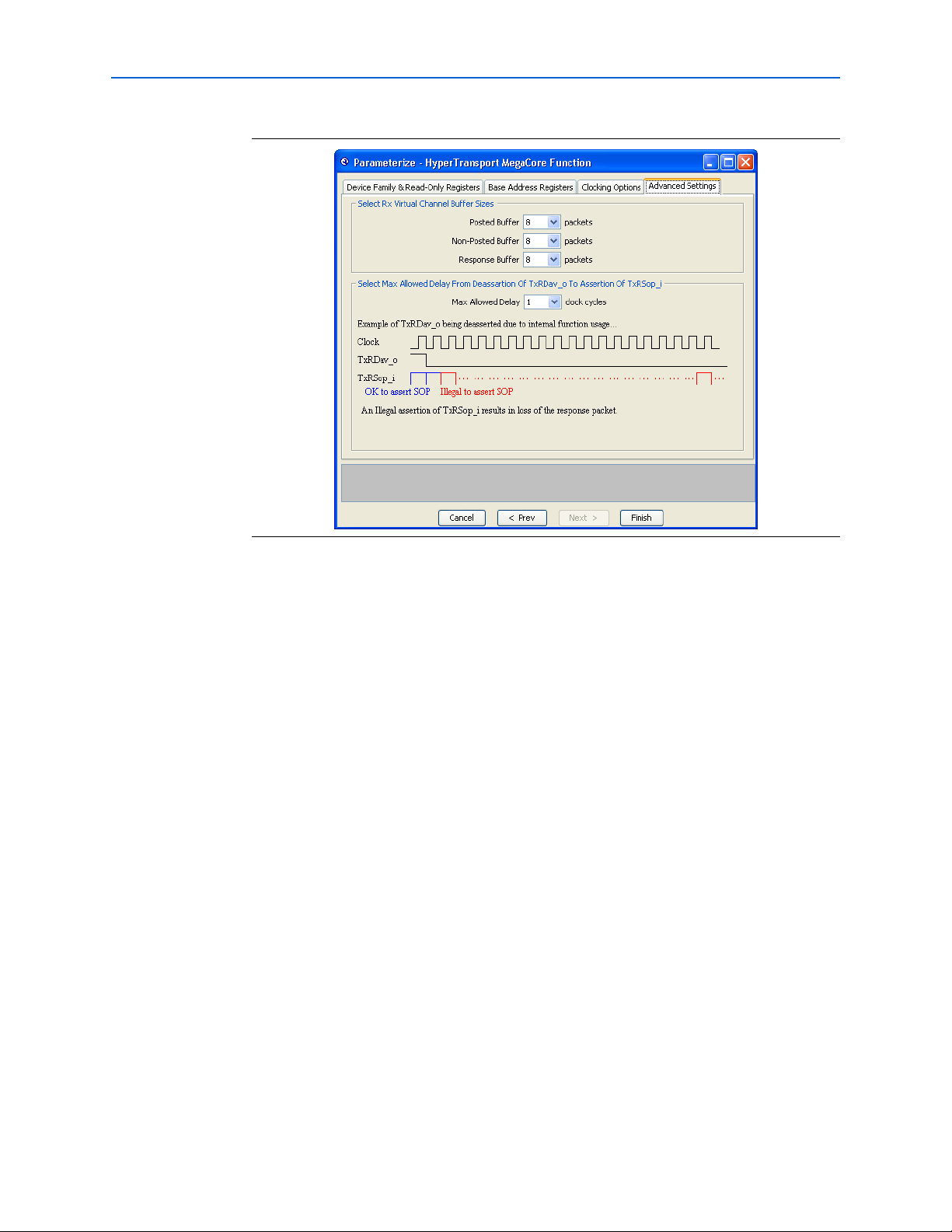
7. Click Next. The Advanced Settings tab displays.
8. You set the receiver virtual channel buffer sizes and the maximum allowed delay
from the deassertion of TxRDav_o to the assertion of TxRSop_i on the Advanced
Settings tab. For more information about these parameters, refer to Table A–4 on
page A–3. For this walkthrough, use the default settings, which are shown in
Figure 2–8.
HyperTransport MegaCore Function User Guide © November 2009 Altera Corporation
Page 17
Chapter 2: Getting Started 2–9
MegaCore Function Walkthrough
Figure 2–8. Parameterize—Advanced Settings Tab
9. Click Finish. The Parameterize—HyperTransport MegaCore Function
Parameterize panel closes and you are returned to the IP Toolbench interface.
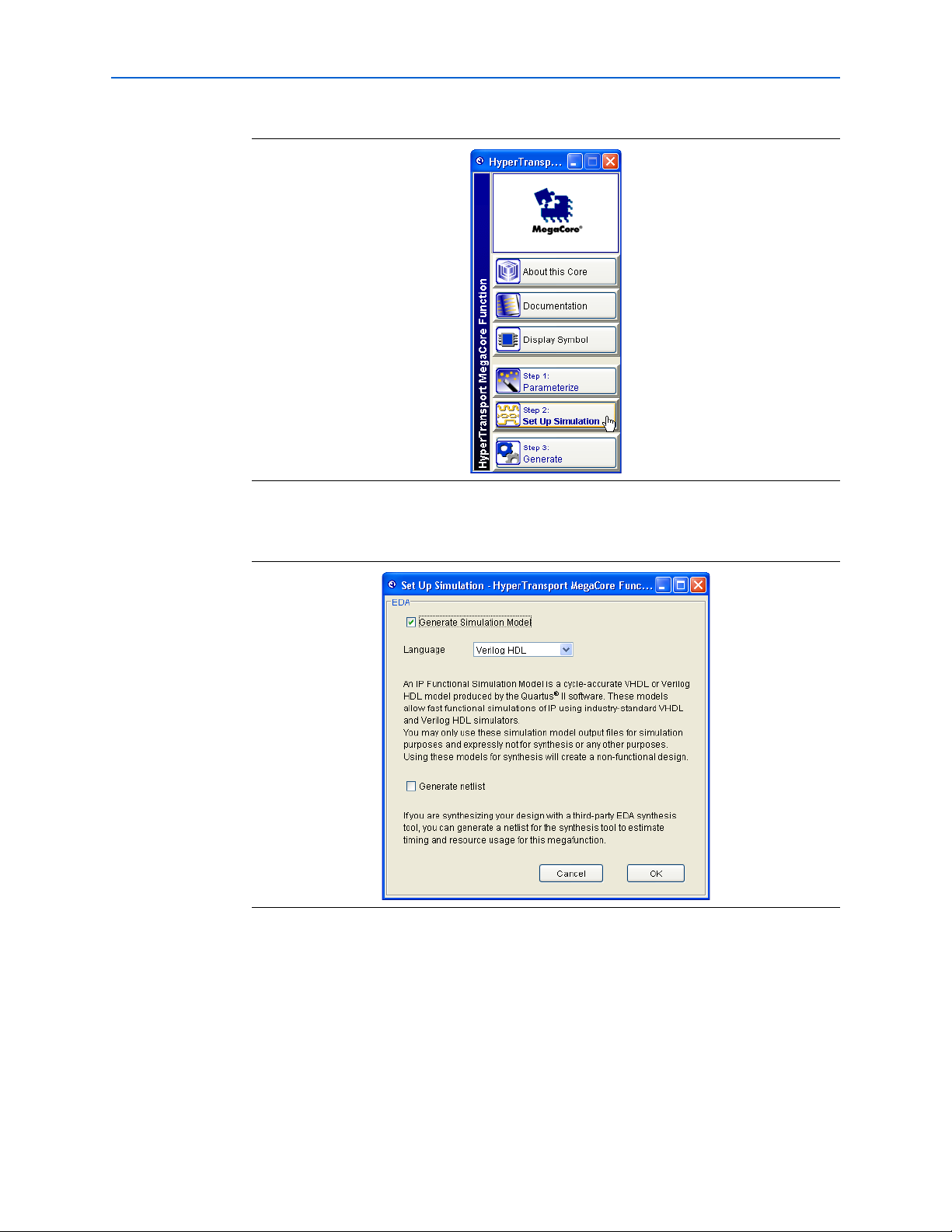
Step 2: Set Up Simulation
An IP functional simulation model is a cycle-accurate VHDL or Verilog HDL model
file produced by the Quartus II software. The simulation model allows for fast
functional simulation of IP using industry-standard VHDL and Verilog HDL
simulators.
1 You may only use these simulation model output files for simulation purposes and
expressly not for synthesis or any other purposes. Using these models for synthesis
creates a nonfunctional design.
To generate an IP functional simulation model for your MegaCore function, follow
these steps:
1. In the IP Toolbench, click Step 2: Set Up Simulation, as shown in Figure 2–9.
© November 2009 Altera Corporation HyperTransport MegaCore Function User Guide
Page 18
2–10 Chapter 2: Getting Started
MegaCore Function Walkthrough
Figure 2–9. Set Up Simulation
2. Turn on Generate Simulation Model, as shown in Figure 2–10.
Figure 2–10. Generate Simulation Model
3. Select the language in the Language list. In this case, Ver i lo g H DL was chosen.
If you are synthesizing your design with a third-party EDA synthesis tool, you can
generate a netlist for the synthesis tool to estimate timing and resource usage for this
megafunction.
1. To generate a netlist, turn on Generate netlist.
2. Click OK.
HyperTransport MegaCore Function User Guide © November 2009 Altera Corporation
Page 19
Chapter 2: Getting Started 2–11
MegaCore Function Walkthrough
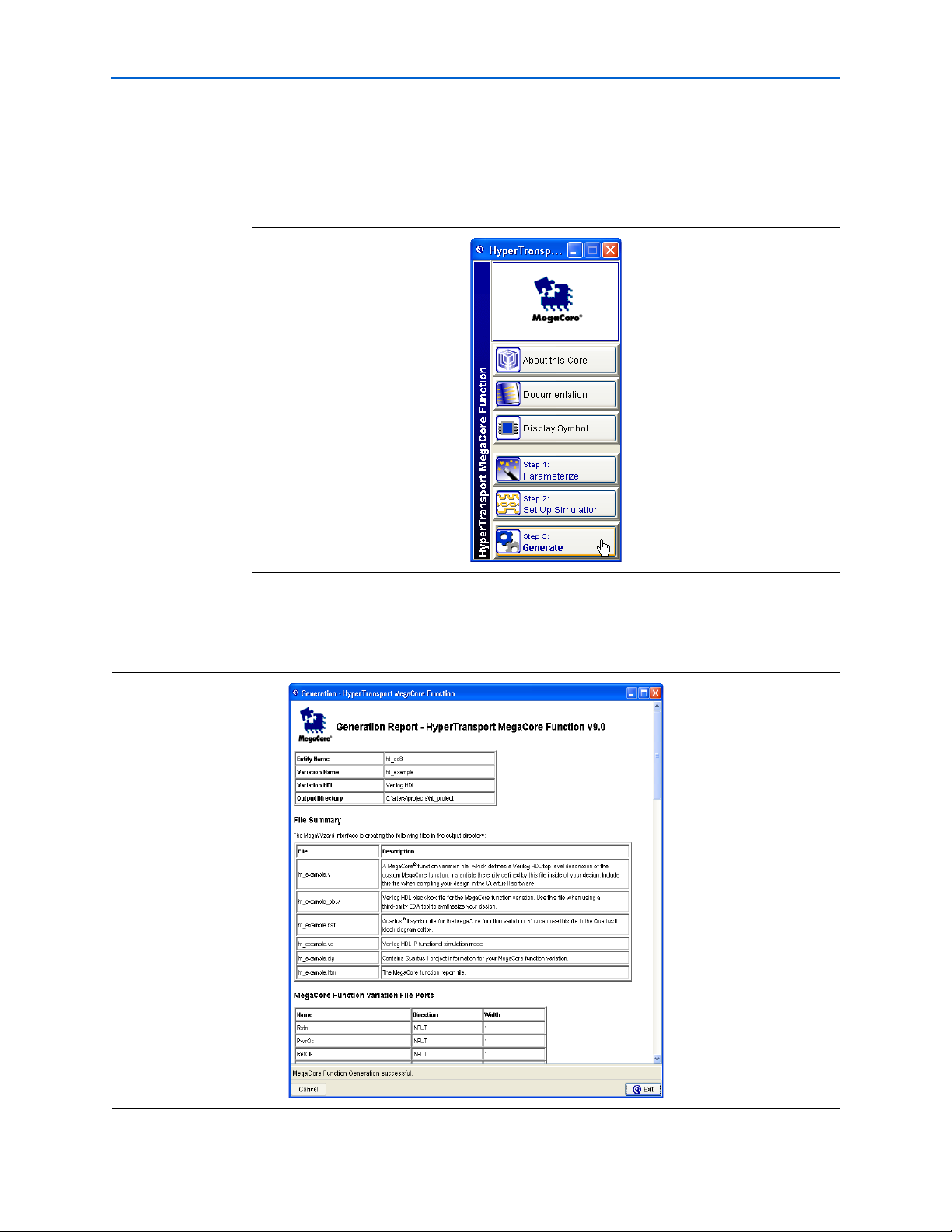
Step 3: Generate
To generate your MegaCore function, follow these steps:
1. In the IP Toolbench, click Step 3: Generate as shown in Figure 2–11.
Figure 2–11. Generation
The generation report lists the design files that the IP Toolbench creates, as shown
in Figure 2–12.
Figure 2–12. Generation Report—HyperTransport MegaCore Function
© November 2009 Altera Corporation HyperTransport MegaCore Function User Guide
Page 20

2–12 Chapter 2: Getting Started
MegaCore Function Walkthrough
2. After the MegaCore function is generated, according to the message and progress
at the bottom of the generation report window, click Exit.
3. If you are prompted to add the Quartus II IP File (.qip) to the project, click Yes .
1 If you previously turned on Automatically add Quartus II IP Files to all
projects, the .qip file is generated automatically.
You have generated an instance of the HyperTransport MegaCore function.
Tab le 2– 1 describes the IP Toolbench-generated files, which are listed in the file
<variation name>.html in your project directory.
Table 2–1. IP Toolbench Files (Note 1)
File Name (2) Description
<variation name>.vhd or .v A MegaCore function variation file, which defines a VHDL or Verilog HDL top-level description
of the custom MegaCore function. Instantiate the entity defined by this file inside your design.
Include this file when compiling your design in the Quartus II software.
<variation name>_bb.v Verilog HDL black-box file for the MegaCore function variation. Use this file when using a
third-party EDA tool to synthesize your design. This file is only produced when the Verilog
HDL language is selected.
<variation name>.bsf Quartus II symbol file for the MegaCore function variation. You can use this file in the
Quartus II block diagram editor.
<variation name>.cmp A VHDL component declaration file for the MegaCore function variation. Add the contents of
this file to any VHDL architecture that instantiates the MegaCore function. This file is only
produced when the VHDL language is selected.
<variation name>.vo or
Verilog HDL or VHDL IP functional simulation model.
<variation name>.vho
<variation name>.qip Contains Quartus II project information for your MegaCore function variation.
<variation name>.html The MegaCore function report file.
Notes to Table 2–1:
(1) These files are variation dependent; some may be absent or their names may change.
(2) <variation name> is the variation name selected by the user in the MegaWizard Plug-In Manager.
1 The .qip file is generated by the MegaWizard interface and contains information
about your generated IP core. You are prompted to add this .qip file to the current
Quartus II project at the time of file generation. In most cases, the .qip file contains all
of the necessary assignments and information required to process the core or system
in the Quartus II compiler. Generally, a single .qip file is generated for each MegaCore
function.
You can now integrate your custom megafunction in your design and compile the
design.
HyperTransport MegaCore Function User Guide © November 2009 Altera Corporation
Page 21

Chapter 2: Getting Started 2–13
Simulate the Design
Simulate the Design
To simulate your design, you use the IP functional simulation models generated by
the IP Toolbench. The IP Functional Simulation model is the .vo or .vho file generated
by the IP Toolbench, as specified in “Step 2: Set Up Simulation” on page 2–9. Add this
file in your simulation environment to perform functional simulation of your custom
variation of the MegaCore function.
The HyperTransport MegaCore function vector-based testbench is an example you
can use to help set up your own simulation environment. You should not attempt to
edit these files. For information about how to perform a simulation using this
vector-based testbench, see “Example Simulation and Compilation” on page 2–16.
f For more information about IP functional simulation models, refer to the Simulating
Altera IP in Third-Party Simulation Tools chapter in volume 3 of the Quartus II Handbook.
You can use any Altera-supported third-party simulator to simulate your design and
testbench.
Compile the Design
You can use the Quartus II software to compile your design. Refer to Quartus II Help
for instructions on compiling your design.
The instructions in this section assume that you named your wrapper file
ht_example.v using the MegaWizard Plug-In Manager. If you chose a different name,
substitute that name when following the instructions.
To compile your design in the Quartus II software, perform the following steps:
1. If you are using the Quartus II software to synthesize your design, skip to step 2. If
you are using a third-party synthesis tool to synthesize your design, perform the
following steps:
a. Set a black box attribute for ht_example.v before you synthesize the design.
Refer to the Quartus II Help for your specific synthesis tool for instructions on
setting black-box attributes.
b. Run the synthesis tool to produce an EDIF Netlist File (.edf) or Verilog Quartus
Mapping file (.vqm) for input to the Quartus II software.
c. Add the .edf or .vqm file to your Quartus II project.
2. On the Processing menu, point to Start and click Start Analysis & Elaboration to
elaborate the design.
3. On the Assignments menu, click Assignment Editor.
4. If the pin names are not displayed, on the View menu, click Show All Known Pin
Names.
© November 2009 Altera Corporation HyperTransport MegaCore Function User Guide
Page 22

2–14 Chapter 2: Getting Started
5. Set the I/O Standard to HyperTransport for the I/O pins that are connected to the
HyperTransport wrapper ports TxCAD_o[7:0], TxCTL_o, TxClk_o,
RxCAD_i[7:0], RxCTL_i, and RxClk_i, by performing the following steps:
a. In the row for the pin, double-click in the Assignment Name column.
b. In the Assignment Name list, click I/O Standard.
c. In the row for the pin, double-click in the Val u e column.
d. In the Value list, click HyperTransport.
6. Set the I/O Standard to 2.5 V for the I/O pins connected to the HyperTransport
wrapper ports PwrOk and Rstn.
7. If you are compiling the HyperTransport MegaCore function variation file
top-level entity in your Quartus II project, set virtual pin attributes for all of the
internal interface signals of the variation.
1 An example Quartus II project that has all of the above I/O standards set,
and virtual pin and clock latency settings, is included with the
HyperTransport MegaCore function installation. Refer to “Example
Quartus II Project” on page 2–16.
Program a Device
8. Turn on the Quartus II timing analysis setting Enable Clock Latency to perform
correct timing analysis. Refer to Quartus II Help for instructions on how to make
this assignment.
9. Set the remaining constraints in the Quartus II software, including the device, pin
assignments, timing requirements, and any other relevant constraints. Refer to
Appendix B, Stratix Device Pin Assignments for more details about assigning
pins. If you have not made pin assignments for your board design, you can use the
Quartus II software to automatically assign pins.
10. On the Processing menu, click Start Compilation to compile the design.
Program a Device
After you compile your design, you can program your targeted Altera device and
verify your design in hardware.
With Altera's free OpenCore Plus evaluation feature, you can evaluate the
HyperTransport MegaCore function before you purchase a license. OpenCore Plus
evaluation allows you to generate an IP functional simulation model and produce a
time-limited programming file.
You can simulate the HyperTransport MegaCore function in your design and perform
a time-limited evaluation of your design in hardware.
1 For more information about OpenCore Plus hardware evaluation for the
HyperTransport MegaCore function, refer to “OpenCore Plus Time-Out Behavior” on
page 3–40 and AN320: OpenCore Plus Evaluation of Megafunctions.
HyperTransport MegaCore Function User Guide © November 2009 Altera Corporation
Page 23

Chapter 2: Getting Started 2–15
Set Up Licensing
Set Up Licensing
You need purchase a license for the MegaCore function only after you are completely
satisfied with its functionality and performance and want to take your design to
production.
After you purchase a license for the HyperTransport MegaCore function, you can
request a license file from the Altera web site at www.altera.com/licensing and install
it on your computer. After you request a license file, Altera emails you a license.dat
file. If you do not have Internet access, contact your local Altera representative.
To install your license, you can either append the license to your Quartus II software
license.dat file or you can specify the MegaCore function’s license.dat file in the
Quartus II software.
1 Before you set up licensing for the HyperTransport MegaCore function, you must
already have the Quartus II software installed on your computer with licensing set
up.
Append the License to Your license.dat File
To append the license, follow these steps:
1. Close the following software if it is running on your computer:
■ Quartus II software
■ MAX+PLUS
■ LeonardoSpectrum™ synthesis tool
■ Synplify software
■ ModelSim
®
II software
®
simulator
2. Open the HyperTransport license file in a text editor. The file should contain one
FEATURE line, spanning 2 lines.
3. Open your Quartus II license.dat file in a text editor.
4. Copy the FEATURE line from the HyperTransport license file and paste it in the
Quartus II license file.
1 Do not delete any FEATURE lines from the Quartus II license file.
5. Save the Quartus II license file.
1 When using editors such as Microsoft Word or Notepad, ensure that the file
does not have extra extensions appended to it after you save (for example,
license.dat.txt or license.dat.doc). Verify the file name in a DOS box or at a
command prompt.
Specify the License File in the Quartus II Software
To specify the MegaCore function’s license file, follow these steps:
© November 2009 Altera Corporation HyperTransport MegaCore Function User Guide
Page 24

2–16 Chapter 2: Getting Started
1 Altera recommends that you give the file a unique name, for example,
<MegaCore name>_license.dat.
1. Run the Quartus II software.
2. On the Tools menu, click License Setup. The Options dialog box opens to the
License Setup page.
3. In the License file box, add a semicolon to the end of the existing license path and
file name.
4. Type the path and file name of the MegaCore function license file after the
semicolon.
1 Do not include any spaces either around the semicolon or in the path or file
name.
5. Click OK to save your changes.
Example Simulation and Compilation
Example Simulation and Compilation
Altera provides example design files in the directory <path>\ht\example, where
<path> is the directory in which you installed the MegaCore function. You can use
these design files to run vector-based simulations and to compile in the Quartus II
software. The example can help you validate the installation of the HyperTransport
MegaCore function in your design environment and serve as an example for setting
up your custom environment.
Example Quartus II Project
Altera provides an example Quartus II project in the directory
<path>\ht\example\quartus that compiles the file <path>\ht\example\ht_top.v.
This project has Quartus II virtual pins assigned for the user-side signals from the
MegaCore function variation. The target device is the EP1S60F1020C6. The pin
assignments used for the HyperTransport link signals support all clocking options.
To compile this example Quartus II project, perform the following steps in the
Quartus II software version 9.1:
1. Start the Quartus II software.
2. On the File menu, click Open Project.
3. In the Open Project dialog box, browse to <path>\ ht\example\quartus.
4. Select the ht_top.qpf file.
5. On the Processing menu, click Start Compilation to compile the project.
Example Simulation with Test Vectors
The example design in directory <path>\ht\example contains the following Verilog
HDL files used in the example simulation:
■ ht_top.vo
■ ht_top_tb.v
HyperTransport MegaCore Function User Guide © November 2009 Altera Corporation
Page 25

Chapter 2: Getting Started 2–17
Example Simulation and Compilation
1 The file ht_top.vo is the IP functional simulation model corresponding to the ht_top.v
variation file included the this directory.
The test vectors consist of the following files:
■ input_ht_vector.dat
■ output_ht_vector.dat
■ input_ui_vector.dat
■ output_ui_vector.dat
When you simulate your design, the top module in the simulation file ht_top_tb.v
reads the input vectors at startup and drives them as test vectors to ht_top.vo. It
compares the outputs from ht_top.vo to the output vectors. If the simulation module
detects a mismatch, it displays an error and the simulation stops. If all of the vectors
match, the simulation displays a message indicating that the test passed. The test
vectors are described in “About the Test Vectors” on page 2–18.
1 The following simulation examples use an IP functional simulation model generated
with the Quartus II software version 9.1. When simulating your design, you must use
the simulation library files supplied with the version of the Quartus II software you
used to create the IP functional simulation model for your MegaCore function
variation.
Simulating Test Vectors Using ModelSim
To simulate with the test vectors interactively, perform the following steps:
1. Start the ModelSim software by executing the vsim command at a system
command prompt or by using the Windows Start menu.
2. In the Modelsim session, change your working directory to the Modelsim example
project directory <path>/ht/example/modelsim.
3. To map the correct libraries, compile the required files, and load and run the
simulation, type the following command:
do run.do r
To simulate with the test vectors without opening a Modelsim session, perform the
following steps:
1. Change your working directory to the ModelSim example project directory
<path>/ht/example/modelsim.
2. To map the correct libraries, compile the required files, and load and run the
simulation, perform one of the following steps:
■ On a supported Windows platform, double-click run.bat or, if scripting, type
the following command:
run r
■ On a supported Linux operating system, at a system command prompt, type
the following command:
./run.sh r
© November 2009 Altera Corporation HyperTransport MegaCore Function User Guide
Page 26

2–18 Chapter 2: Getting Started
Example Simulation and Compilation
About the Test Vectors
The example design has a host connected to an instance of the HyperTransport
MegaCore function configured as an end-chain link. When simulating the receive link
interface, the following events occur:
1. The host configures the end chain link’s BAR0 with 0xfa000000. It then writes
0x01 as the UnitID and 0x0007 in the command register of the device header
space.
2. The host writes double-word data with data ranging from 1 to 16 DWORDs to the
posted channel followed by a byte write with data ranging from 1 to 8 DWORDs.
3. The host writes double-word data with data ranging from 1 to 16 DWORDs to the
non-posted channel followed by a byte write with data ranging from 1 to 8
DWORDs.
4. The host performs a read request with data ranging from 1 to 16 DWORDs to the
non-posted channel followed by a byte read request with data ranging from 1 to 8
DWORDs.
Analyzing the transmit local-side interface, the following sequence of events occurs:
1. The local side writes double word data with data ranging from 1 to 16 DWORDs to
the posted channel followed by a byte write with data ranging from 1 to 8
DWORDs.
2. The local side writes double word data with data ranging from 1 to 16 DWORDs to
the non-posted channel followed by a byte write with data ranging from 1 to 8
DWORDs.
3. The local side performs a read request with data ranging from 1 to 16 DWORDs to
the non-posted channel followed by a byte read request with data ranging from 1
to 8 DWORDs.
HyperTransport MegaCore Function User Guide © November 2009 Altera Corporation
Page 27

HyperTransport Technology Overview
HyperTransport
Device A
Control Pair
Clock Pair
2, 4, 8, 16, or 32 Data Pairs
Clock Pair
Control Pair
2, 4, 8, 16, or 32 Data Pairs
RESET_L
PWROK
V
HT
GND
HyperTransport
Device B
HyperTransport technology (HT) is packet-based point-to-point link that is designed
to deliver a scalable, high-performance interconnect between the CPU, memory, and
I/O devices on a circuit board. The HT link uses low-swing differential signaling with
differential termination to achieve high data rates from 400 Megabytes per second
(Mbytes/s) to 1.6 Gigabytes per second (Gbytes/s) per direction, assuming an 8-bit
interface.
The HT link provides significantly more bandwidth than competing interconnect
technologies; it uses scalable frequency and data width to achieve scalable
bandwidth. Designers can use HT in networking, telecommunications, computer, and
high-performance embedded applications, and in applications that require high
speed, low latency, and scalability.
The HT link consists of two independent, source-synchronous, clocked, and
unidirectional sets of wires, as illustrated in Figure 3–1.
3. Specifications
Figure 3–1. HT Link
f For additional information, refer to the HyperTransport I/O Link Specification Revision
1.03.
HT systems consist of two or more HT devices. The HyperTransport specification
includes the following device types:
■ Host Bridge—A host bridge is the HT interface that provides connectivity to the
system’s host processor. Because all communication within an HT chain is
between individual devices and the host bridge, the host bridge includes
additional functionality such as managing peer-to-peer packets and handling error
conditions.
© November 2009 Altera Corporation HyperTransport MegaCore Function User Guide
Preliminary
Page 28

3–2 Chapter 3: Specifications
Host Bridge
(Master)
HT Link
Interface
Mem
Tunnel
Tunnel
HT Link
Interface
Tree
CPU
Tunnel
HT-to-HT Bridge
HT Link
(P)
HT Link
(S)
End-Chain
HT Link
Interface
End-Chain
HT Link
Interface
Primary
Chain
Secondary
Chain
Host Bridge
HT Link
Interface
Tunnel
Tunnel
HT Link
Interface
Tunnel
Tunnel
HT Link
Interface
End-Chain
HT Link
Interface
Chain
Mem
CPU
HyperTransport Technology Overview
■ End-Chain Link—The end-chain link device is the simplest of all HT devices and
only one can exist in an HT chain. This single-link device claims packets when the
destination address of the packet matches its address. If it receives a packet that
does not match its address, it must indicate an error condition by setting
appropriate error bits or sending a return packet indicating that an error occurred.
The Altera
■ Tu n ne l —A tunnel is a dual-link device that is not a
HyperTransport MegaCore function implements an end-chain link.
HyperTransport-to-HyperTransport bridge. In the upstream direction, tunnels
transfer all packets except for information packets directly from the downstream
link to the upstream link. In the downstream direction, only packets that are not
claimed by the device are transferred to the downstream interface.
■ HyperTransport-to-HyperTransport Bridge—This bridge has one or more HT links
and is more complex than a tunnel because it translates packets from one chain to
two or more chains. The bridge must take upstream traffic from secondary chains
and forward the packets to the primary chain while maintaining I/O streams,
virtual channel ordering, and error conditions.
HT Systems
Figure 3–2. HT Systems
HT systems, or fabrics, are implemented as one or more daisy chains of HT devices.
Figure 3–2 shows two of the three variations of HT fabric configurations. You can use
the HyperTransport MegaCore function as the end-chain link in any of these systems.
Preliminary
HyperTransport MegaCore Function User Guide © November 2009 Altera Corporation
Page 29

Chapter 3: Specifications 3–3
HyperTransport MegaCore Function Specification
HT Flow Control
All commands and data are separated into one of three separate virtual channels,
which provide higher performance and allow certain types of requests to pass others
to avoid deadlocks. However, in some cases, requests in one channel cannot pass
those in other channels to preserve ordering as required by systems. The three virtual
channels are:
■ Non-Posted Requests—Requests that require a response (all read requests and
optionally write requests)
■ Posted Requests—Requests that do not require a response (typically write requests)
■ Responses—Responses to non-posted requests (read responses or target done
responses to non-posted writes)
The HT flow control mechanism is a credit-based scheme maintained per virtual
channel for an individual link. A transmitter consumes a buffer credit each time it
transmits a packet and cannot transmit a packet to the receiver unless a buffer credit is
available. The receiver provides buffer credits for each available buffer at link
initialization, and it provides an additional buffer credit each time a buffer is freed
thereafter.
Buffer credits are transmitted in the opposite direction of the data flow as part of NOP
packets.
HyperTransport MegaCore Function Specification
This section describes the functionality and features of the 8-bit end-chain
HyperTransport MegaCore function. Figure 3–3 shows the block diagram of the
HyperTransport MegaCore function. The HyperTransport MegaCore function is
partitioned into three layers:
■ Physical Interface
■ Synchronization and Alignment
■ Protocol Interface
© November 2009 Altera Corporation HyperTransport MegaCore Function User Guide
Preliminary
Page 30

3–4 Chapter 3: Specifications
TxPHY
Rx Alignment
Tx Alignment
Rx
Claimed
Buffers
Rx Packet
Processor
Tx Packet
Buffering
End-
Chain
Handler
Tx Packet
Scheduling
&
Framing
Protocol InterfaceSynch & AlignmentPhysical Interf a c e
Reset Generation
RxPHY
Tx Clock
Generation
RxClk_i
RxCAD_i[7:0]
RxCTL_i
TxClk_o
TxCAD_o[7:0]
TxCTL_o
Rstn
PwrOk
C
S
R
Rx
Interface
Tx &Rx
Buffer Credit
Counters
CSR
Interface
Rx
Sync
FIFO
Tx
Interface
Tx
Sync
FIFO
Rx Response Req /Data
Rx Posted Req/Dat a
Rx Non-Poste d Req/Data
Tx Response Req/Data
Tx Posted Req/Data
Tx Non-Posted Req/Data
Rx Clock
Generation
×2
÷4
Rx Link Clock Divided by 4
×8
×4
Ref Clk
HyperTransport MegaCore Function Specification
Figure 3–3. HyperTransport MegaCore Function Block Diagram
Physical Interface
The physical interface module contains the logic that interfaces the HyperTransport
MegaCore function to the physical link signals. It contains the logic for both the
receiver and transmitter portions. The SERDES functionality is embedded into the
Altera device to ensure operation at maximum speed.
Rx Deserialization Logic and Clock Generation
This module receives serial data from each RxCTL_i and RxCAD_i bit and converts it
to a parallel data stream. The Rx clock generator (implemented in a fast PLL)
multiplies the receiver Rx link RxClk_i by two to capture RxCTL_i and RxCAD_i.
The data is then deserialized by a factor of eight and clocked by a divided-by-four
clock for use in the synchronization and alignment layer.
Tx Serialization Logic and Clock Generation
This module transmits serial data on the link interface. Data is transferred from the
internal module in parallel and is serialized on the link interface. The data entering
this module is already split into channels. The serialization circuit drives TxCAD_o
and TxCTL_o. The Tx clock generator multiplies the Tx alignment logic clock by eight
to serialize the TxCTL_o and TxCAD_o signals, and generates a multiplied-by-four
clock for use as the HT TxClk_o.
Synchronization and Alignment
The synchronization and alignment layer is responsible for synchronizing clock
domains and aligning data to the natural boundaries.
HyperTransport MegaCore Function User Guide © November 2009 Altera Corporation
Preliminary
Page 31

Chapter 3: Specifications 3–5
HyperTransport MegaCore Function Specification
Rx Synchronization and Alignment Interface
The Rx synchronization and alignment interface performs the following functions:
■ Bit-to-Byte Alignment—The interface performs link initialization sync packet
detection and byte alignment so that the first received byte of data is placed in byte
0 of the internal 64-bit data path.
■ CRC Checking—The interface checks the link CRC.
■ Synchronization—The interface writes all non-CRC data to an Rx synchronization
FIFO buffer so that the data can be synchronized to the protocol interface clock
domain for the protocol interface layer.
1 If you turn on the Shared Rx/Tx/Ref Clock option in the IP Toolbench
parameterization wizard, the IP Toolbench removes the Rx synchronization
FIFO buffer from the design to reduce latency. Refer to “Clocking Options”
on page 3–7 for more information about clock options.
Tx Alignment Interface
The Tx alignment interface performs the following functions:
■ Synchronization—The interface reads transmit data from the Tx synchronization
FIFO buffer to move the data from the protocol interface clock domain to the Tx
alignment clock domain.
Protocol Interface
1 If you turn on the Shared Ref/Tx Clock or Shared Rx/Tx/Ref Clock option
in the wizard, the wizard removes the Tx synchronization FIFO buffer from
the design to reduce latency. Refer to “Clocking Options” on page 3–7 for
more information about clock options.
■ Link Initialization—The interface generates the link initialization sequence when
the link is reset.
■ CRC Generation—The interface generates CRCs.
The protocol interface module has a 64-bit data path. It receives formatted packets
from the Rx synchronization and alignment module and transmits packets to the Tx
alignment module. Because the HT specification requires that traffic in the three
different virtual channels (posted, non-posted, and responses) be kept independent,
the module maintains internal packet buffering and the local interface separately for
each virtual channel. The following sections describe the protocol interface blocks and
their function.
Rx Packet Processor
The Rx packet processor reads the data stream from the Rx sync FIFO buffer. It parses
the data and determines whether packets should be claimed or passed to the end
chain handler.
© November 2009 Altera Corporation HyperTransport MegaCore Function User Guide
Preliminary
Page 32

3–6 Chapter 3: Specifications
HyperTransport MegaCore Function Specification
If the Rx request address matches one of the BAR registers in the CSR module, the Rx
packet processor claims the packet and writes to the Rx posted buffer or the Rx
non-posted buffer. If the UnitID in an Rx response matches the UnitID in the CSR, the
processor claims the packet and writes to the Rx response buffer. The processor claims
data packets and writes to the appropriate Rx buffer if it claimed the associated
request or response packet.
The Rx packet processor passes unclaimed packets to the end-chain handler.
End-Chain Handler
The end-chain handler logs errors when it receives a response or posted packet. It also
generates NXA response packets when it receives a non-posted packet.
Rx Claimed Buffers
The traffic written to the claimed packet buffers is stored in the appropriate virtual
channel buffer. The packets are stored in the order in which they are received from the
link. When reading the packets from the buffers, you read commands followed by any
associated data.
To allow maximum throughput of the command packets, command packets are
stored in registers. Data packets, on the other hand, are stored in dual-port memory
blocks.
Although data packets and command packets are stored in separate storage elements,
when the user interface reads those packets it appears as though they are stored in the
same location. That is, the user interface sees a command packet followed by the data,
consecutively.
Tx Buffers
The Tx buffers are temporary storage for the traffic to be transmitted on the Tx path.
The user logic writes packets to the buffer with the command as the first word written
followed by any data associated with that command. Tx buffers automatically adjust
for 32-bit commands or 64-bit commands by inserting idle NOP packets in the upper
bits of a 32-bit command, such as a read response. Additionally, because the
transmitted data may be an odd number of DWORDS, the Tx buffers insert a NOP
packet from the NOP generator to align the end of packet to the 64-bit boundary,
placing the next packet start command on the lower DWORD. The Tx buffers also
generate appropriate CTL information for transmission to the link.
Scheduler
The scheduler ensures equal access to all HT virtual channels. The scheduler is an
arbiter that performs round-robin arbitration between the response, non-posted, and
posted buffers. Additionally, the scheduler gives a higher priority to the NOP
generator so that if a NOP packet with flow control information is available at the end
of a packet transmission, the scheduler allows it to be transmitted before starting a
new packet transmission from another virtual channel.
HyperTransport MegaCore Function User Guide © November 2009 Altera Corporation
Preliminary
Page 33

Chapter 3: Specifications 3–7
32-Bit Command
Followed by 28-Byte Data
64-Bit Command
Followed by
16-Byte Data
32-Bit Command
64-Bit Command
Followed by
32-Byte Data
Command
Data
Idle NOP
Flow Control NOP
HyperTransport MegaCore Function Specification
Figure 3–4 shows example transmitter traffic. This example assumes that each square
represents one DWORD. The top square is the low DWORD and the bottom square is
the high DWORD. In Figure 3–4, the leftmost information transmits first. The vertical
dashed lines delineate packets. The idle NOP packets are NOP packets inserted to
align data and never contain flow control information. Flow control NOP packets are
read from the NOP generator and may or may not contain flow control information,
depending on the buffer release status generated by the Rx claimed buffers.
Figure 3–4. Example Transmission in the Tx Interface
Clocking Options
CSR Module
The CSR module reads packets from the non-posted buffer and checks whether they
are CSR access packets. This process allows the HyperTransport MegaCore function
to use the same buffers for the CSR interface that it uses for general non-posted traffic,
reducing the size of the MegaCore function variation. If a packet is a CSR access (read
or write request) it is routed to the CSR interface module instead of the user interface.
Normal non-posted traffic is provided directly to the local user interface.
The CSR module contains all of the CSR registers and provides read/write capability
to them. It also generates the appropriate response to CSR accesses in the Tx response
buffer.
The HyperTransport MegaCore function has three distinct clock domains:
■ Protocol interface clock domain
■ Rx alignment clock domain
■ Tx alignment clock domain
The MegaCore function has three clocking options that link clock domains together to
reduce overall latency and resource usage. Due to the HT protocol flow control
mechanism, the clocking option you choose results in different latency for the flow
control information inside the HyperTransport MegaCore function, which can affect
your overall system performance.
© November 2009 Altera Corporation HyperTransport MegaCore Function User Guide
Preliminary
Page 34

3–8 Chapter 3: Specifications
HyperTransport MegaCore Function Specification
Shared Rx/Tx Clock
When you turn on the Shared Rx/Tx Clock option, the Rx alignment logic, protocol
interface logic, and Tx alignment logic operate as independent clock domains with
synchronization FIFO buffers buffering data between the modules, as shown in
Figure 3–5. The Rx and Tx clocks share the same PLL, and are synchronous. This
implementation provides the most flexible design because the reference clock
(RefClk) frequency and phase can be determined by other requirements the user
application may impose, and the HT Tx link clock is always synchronous with the HT
Rx link clock.
Figure 3–5. Shared Rx/Tx Clock Option
RxClk_i
TxClk_o
Phy Synch & Alignment Protocol Interface
PLL
×1
÷4
×2
Rx
SerDes
Tx
SerDes
Rx
Alignment
Logic
Tx
Alignment
Logic
Rx
Sync
FIFO
Tx
Sync
FIFO
Protocol
Interface
Logic
RxLnkClkD4
RefClk
The Tx sync and Rx sync FIFO buffers consume logic resources and add latency to the
HyperTransport MegaCore function. This increased latency can limit the link
throughput if the attached HT device has a small number of buffer credits. The
latency increases the turnaround time for receiving a new buffer credit after
transmitting a packet.
The design must meet the following clock frequency requirements when using the
Shared Rx/Tx Clock option:
■ The frequency of RefClk must be greater than or equal to RxLnkClkD4.
■ When RefClk and RxLnkClkD4 are nominally equal but are derived from
different sources, RefClk must be no more than 2,000 ppm slower than
RxLnkClkD4.
1 Failing to meet these requirements will result in system failure due to Tx sync FIFO
buffer underflow or Rx sync FIFO buffer overflow.
In most designs, you would not connect RxLnkClkD4 to anything external to the
HyperTransport MegaCore function, but it is provided for monitoring purposes if
needed.
Shared Ref/Tx Clock
The Shared Ref/Tx Clock option reduces the latency through the HyperTransport
MegaCore function by eliminating the Tx sync FIFO buffer. The MegaCore function
uses RxLnkClkD4 for the Rx alignment logic only, and uses the RefClk for the rest of
the logic, including the Tx alignment logic, as shown in Figure 3–6.
HyperTransport MegaCore Function User Guide © November 2009 Altera Corporation
Preliminary
Page 35

Chapter 3: Specifications 3–9
RxClk_i
Tx
Alignment
Logic
Rx
Sync
FIFO
RefClk
Phy Synch & Alignment Protoco l Interface
Protocol
Interface
Logic
Rx
SerDes
RxLnkClkD4
TxClk_o
PLL
Tx
SerDes
PLL
÷4
Rx
Alignment
Logic
×2
×4
×8
HyperTransport MegaCore Function Specification
Figure 3–6. Shared Ref/Tx Clock Option
The design must meet the following clock frequency requirements when using the
Shared Ref/Tx Clock option:
■ The frequency of RefClk must be greater than or equal to RxLnkClkD4.
■ When RefClk and RxLnkClkD4 are nominally equal but are derived from
different RxLnkClkD4, RefClk must be no more than 2,000 ppm slower than
RxLnkClkD4.
■ RefClk should run at 50, 75, 100, or 125 MHz to create the allowed HT clock
frequencies of 200, 300, 400, or 500 MHz.
1 Failing to meet these requirements results in system failure due to Tx sync FIFO buffer
underflow or Rx sync FIFO buffer overflow.
Additionally, the attached HT device may require its incoming HT link clock to be less
than or equal to its outgoing HT link clock. This requirement—along with the above
requirements—forces the RefClk frequency to be within 2,000 ppm of the
RxLnkClkD4 frequency.
1 This clocking option may not be strictly compliant with the HT specification. If
RefClk runs at a frequency other than 50 MHz, TxLnkClk does not run at the
required 200 MHz upon reset. However, in many embedded applications it may be
acceptable for the TxLnkClk to operate at 300, 400, or 500 MHz upon reset.
Depending on the time base of the supplied RefClk, the Shared Ref/Tx Clock option
implements an asynchronous or synchronous HT implementation. The time base for
the RefClk can be asynchronous or synchronous with the attached receiver’s time
base.
In most designs, you would not connect RxLnkClkD4 to anything external to the
HyperTransport MegaCore function, but it is provided for monitoring purposes if
needed.
© November 2009 Altera Corporation HyperTransport MegaCore Function User Guide
Preliminary
Page 36

3–10 Chapter 3: Specifications
HyperTransport MegaCore Function Specification
Shared Rx/Tx/Ref Clock
When you use the Shared Rx/Tx/Ref Clock option, RxLnkClkD4 is used for the entire
HyperTransport MegaCore function and the local side interfaces. This
implementation provides the lowest latency MegaCore function variation and
typically results in the highest performance, and is a synchronous HT clock
implementation. All of the user logic that interfaces to the HyperTransport MegaCore
function must operate using RxLnkClkD4. This option is illustrated in Figure 3–7.
Figure 3–7. Shared Rx/Tx/Ref Clock Option
RxClk_i
TxClk_o
Phy Synch & Alignment Protocol Interface
PLL
×1
÷4
×2
Rx
SerDes
Tx
SerDes
Rx
Alignment
Logic
Tx
Alignment
Logic
Protocol
Interface
Logic
RxLnkClkD4
In this case, the Rx sync FIFO buffer and the Tx FIFO buffer are removed, yielding the
best throughput performance (i.e., the lowest latency through the MegaCore function
variation.)
1 You cannot use the RefClk input if you use the Shared Rx/Tx/Ref Clock option.
HyperTransport MegaCore Function Parameters and HT Link Performance
This section describes how the Rx buffer size parameters and clocking options of the
HyperTransport MegaCore function relate to throughput on the HT Link interface.
Refer to section 4.8 of the HyperTransport I/O Link Specification Revision 1.03 for
information about the flow control mechanism before reading this section.
The HT flow control mechanism is a credit-based scheme in which the transmitter
maintains a counter for each type of buffer in the receiver. When the link initializes,
the transmitter resets all of the counters to zero. When link initialization completes,
each receiver has its transmitter send buffer credits (transmitted within NOP
commands) for each type of buffer to indicate the number of buffers available for each
type of packet. When the transmitter transmits a packet of a particular type it
decrements that counter by one. The transmitter cannot transmit a packet if the count
for that type of packet is 0. After the receiver processes the packet and frees up the
buffer, it has its transmitter send a buffer credit for that type back to the original
transmitter.
The transmitter maintains six counters, one for each type of packet. If a command
packet has an associated data packet, the transmitter must ensure that it has credits
for both the control and data buffer types. Therefore, for most traffic on the HT link
interface, think of a pair of data and control counters as one. For simplicity, the rest of
this discussion refers to the control and data counters for each virtual channel as one
counter.
HyperTransport MegaCore Function User Guide © November 2009 Altera Corporation
Preliminary
Page 37

Chapter 3: Specifications 3–11
HyperTransport MegaCore Function Specification
For applications that require large bursts of data to be transmitted on one virtual
channel, the counter of that virtual channel can limit the throughput. This situation
occurs because when the counter reaches zero, no additional packets can be
transmitted in that virtual channel. If another virtual channel has no packets to be
transmitted, the link is idle until more credits are received. To maximize the
throughput in this type of application, you must prevent or minimize idle time on the
link by ensuring that new credits are received before the counter reaches zero. This
implementation ensures continuous transfer until all data is transmitted.
Figure 3–8 shows the components of the HT flow control loop for a single virtual
channel. The loop is from the time Transmitter A decrements its available Rx buffer
counter until the time that counter is incremented.
Figure 3–8. HT Flow Control Loop (Note 1)
Transmitter A
Tx Buffer
1
1
Available Rx
Buffer
Counter
FIFO
2 3 4
Receiver B
Rx Bu ffe rFIFO
8
NOP
Decoder
Receiver A
FIFO
FIFO
567
Transmitter B
4
NOP
Generator
Note to Figure 3–8:
(1) Numbered steps are described in the following sections.
Figure 3–8 demonstrates the following flow:
1. Transmitter A schedules a packet for transmission and transfers it to the Tx FIFO
buffer. At the same time, the locally maintained available Rx buffer counter is
decremented.
2. The command is read out of the Tx FIFO buffer and transferred across the HT link
to receiver B’s Rx FIFO buffer.
3. The command is read out of the Rx FIFO buffer, decoded, and written into the Rx
buffer.
4. The user-side logic reads the command from the Rx buffer and frees the buffer. The
buffer free indication is transferred to the NOP generator in transmitter B.
5. The NOP containing the Rx buffer credit information is scheduled for transmission
and written into transmitter B’s Tx FIFO buffer.
6. The NOP is read out of transmitter B’s Tx FIFO buffer and transferred across the
HT link to receiver A’s Rx FIFO buffer.
7. The NOP is read out of receiver A’s Rx FIFO buffer and decoded.
© November 2009 Altera Corporation HyperTransport MegaCore Function User Guide
Preliminary
Page 38

3–12 Chapter 3: Specifications
HyperTransport MegaCore Function Specification
8. The Rx buffer credit is sent to transmitter A’s available Rx buffer counter, allowing
it to be incremented.
If the number of Rx buffers is large enough, the virtual channel can have a high loop
time and continuous transmission. For example, if you assume that transmitter A has
not transmitted packets for a particular virtual channel for some time, the avaliable Rx
buffer counter in transmitter A is equal to the total number of Rx buffers for that
virtual channel in receiver B. If transmitter A now begins transmitting a large burst of
packets on that virtual channel, the first buffer credit must make it back to increment
the counter before it has decremented to zero to ensure continuous transmission
without interruption. This process repeats and allows the burst to be transmitted
uninterrupted by the counter until the burst is finished.
On the other hand, if the number of Rx buffers is small and the flow control loop time
is high, the counter decrements to zero before the first buffer credit makes it back. In
this case, the burst is interrupted by the counter until the first buffer credit makes it
back. Assuming no other virtual channels have packets available to transmit,
transmitter A is forced to transmit NOPs, limiting the overall utilization of the link.
After the first buffer credit is received, transmitter A immediately transmits another
packet and decrements the counter to zero. The virtual channel is stalled until the next
buffer credit is received.
The typical packet size also affects the throughput. Larger packets take longer to
transmit, so the decrement rate of the available Rx buffer counter is relatively slow.
Thus, large packets permit a longer loop time because the counter takes longer to
decrement to zero.
1 Non-posted reads are command-only requests. A burst of non-posted reads can be
transmitted very rapidly and a large number of available non-posted Rx buffers can
be exhausted quickly. However, the overall throughput of reads is actually limited by
the throughput of the response virtual channel in the opposite direction where both
command and data packets are being transferred. As long as the number of
non-posted Rx buffers is greater than or equal to the number of Rx response buffers
available at the opposite end of the link, the Rx non-posted buffer count does not limit
the overall read throughput.
In applications that use a mix of packets on multiple virtual channels, the decrement
rate of the available Rx buffer counter on a particular channel is slower. This rate
allows a smaller number of Rx buffers per virtual channel or a longer loop time.
The HyperTransport MegaCore function provides two features that allow you to
adjust actual throughput, depending on the HT device to which the MegaCore
function is connected:
■ Rx buffer size
■ Clocking options
The HyperTransport MegaCore function allows you to adjust the Rx buffer size for
each virtual channel. Therefore, reasonably long flow control loop times and typical
packet sizes of 32 bytes, as opposed to the maximum 64 bytes, can be tolerated with
no loss in throughput for traffic received by the HyperTransport MegaCore function.
HyperTransport MegaCore Function User Guide © November 2009 Altera Corporation
Preliminary
Page 39

Chapter 3: Specifications 3–13
HyperTransport MegaCore Function Specification
When the attached HT device has a limited number of Rx buffers (on the order of four
or less), you can adjust the HyperTransport MegaCore function clocking option to
minimize the loop time. In this case, the flow control loop time is critical for
maintaining high throughput on HT link traffic transmitted from the HyperTransport
MegaCore function. By adjusting the clocking option, you can remove either the Tx
FIFO buffer or both the Tx and Rx FIFO buffers. Removing one or both buffers
increases throughput by removing the latency through the FIFO buffers. If you must
maintain maximum throughput on a single virtual channel with a small number of Rx
buffers, then use either the Shared Ref/Tx Clock or Shared Rx/Tx/Ref Clock option.
Using the Shared Ref/Tx Clock option removes the Tx FIFO buffer. Using the Shared
Rx/Tx/Ref Clock option removes both the Tx and Rx FIFO buffers.
Refer to Table A–3 on page A–3 and Table A–4 on page A–3 for information about the
clocking option and Rx buffer size parameters.
© November 2009 Altera Corporation HyperTransport MegaCore Function User Guide
Preliminary
Page 40

3–14 Chapter 3: Specifications
HyperTransport MegaCore Fun ction
RxCA D_i[7:0]
RxCTL_i
RxClk_i
TxCAD_o[ 7
:0]
TxCTL_o
TxClk_o
PwrOk
Rst n
RxNpDat_o[63:0]
RxNpVal_o
RxNpDav _o
RxNpEna_i
TxREop_i
Rx Non-Posted
Command/Data
Buffer Interface
Rx Posted
Command/Data
Buffer Interface
Rx Response
Command/Data
Buffer Interface
Tx Non-Posted
Command/Data
Buffer Interface
Tx Posted
Command/Data
Buffer Interface
Tx Response
Command/Data
Buffer Interface
HT Link
Rx Signals
HT Link
System
Signals
HT Link
Tx Signals
Rx Inter fa ce
Tx Interface
TxPDat_i[63:0]
TxPMty_i[2:0]
TxPDav_o
TxPSop_i
TxPDatEna_i
TxPEop_i
TxPWrRjct_o
TxRDat_ i[63:0]
TxRMty_i[2:0]
TxRDav_o
TxRSop_i
TxRD atEna_i
TxNpDat_i[63:0]
TxNpMty_i[2:0]
TxNpDav _o
TxNpSop_i
TxNpD atEna_i
TxNpEop_i
TxNpWr Rjc t_o
TxRWr Rjct_o
CsrCmdReg_o[15:0]
CsrStatReg_o[15:0]
CsrCapCmdReg_o[15:0]
CsrCapLnk0CtrlReg_o[15:0]
CsrCapLnk1CtrlReg_o[15:0]
CsrCapLnk0CfgReg_o[15:0]
CsrCapLnk1CfgReg_o[15:0]
CsrCapFtrReg_o[7:0]
CsrCapLnk0ErrReg_o[3:0]
CsrCapLnk1ErrReg_o[3:0]
CsrCapErrHndlngReg_o[15:0]
CSR Module Signals
RxNpCmdBarHit_o[ 2:0]
RxNpEop_o
RxNpSop_o
RxNpMty _o[2:0]
RxPDat_o[63:0]
RxPVal_o
RxPDav_o
RxPEna_i
RxPCmdBarHit_o[2:0]
RxPEop_o
RxPS op_o
RxPMty_o[2:0]
RxRDat_o[63:0]
RxRV al_o
RxRDav_o
RxREna_i
RxREop_o
RxRSop_o
RxRMty_o[2:0]
RespErr
SignaledTabrt
Bar0Reg_o[31:0]
Bar1Reg_o[31:0]
Bar2Reg_o[31:0]
Bar3Reg_o[31:0]
Bar4Reg_o[31:0]
Bar5Reg_o[31:0]
ClmdRCmdBuf Ovr Flw Err_o
ClmdNPCmdBufOvrFlwErr_o
ClmdPCmdBuf OvrFlw Er r_o
Buffer Overflow
Indicator Signals
Ref Clk
RxLnkClkD4
Ref ClkWrmRst
Ref ClkCldRs t
System Signals
RxLnkCl kD4Locked_o
TxPllAreset_i
RxPllAreset_i
HyperTransport MegaCore Function Specification
Signals
Figure 3–9 shows a top-level view of the HyperTransport MegaCore function interface
signals.
Figure 3–9. Top-Level HyperTransport MegaCore Function Sign
HyperTransport MegaCore Function User Guide © November 2009 Altera Corporation
The HT interface signals are also external I/O pins on the chip. Each HT interface
signal is in one of the following groups:
■ HT link Rx signals
■ HT link system signals
■ HT link Tx signals
Preliminary
Page 41

Chapter 3: Specifications 3–15
HyperTransport MegaCore Function Specification
The local application interface uses an Altera Atlantic interface to transfer data to the
local-side application. The local application interface has the following signal groups:
■ Rx non-posted command/data interface
■ Rx posted command/data interface
■ Rx response command/data interface
■ Tx non-posted command/data interface
■ Tx posted command/data interface
■ Tx response command/data interface
■ CSR interface
■ System signals
The following sections describe these signal groups.
f The local application interfaces to the Rx and Tx command/data buffers using the
Altera Atlantic interface. For a detailed description of the Atlantic interface, refer to FS
13: Atlantic Interface.
Tab le 3– 1 offers an overview of the Atlantic interface information in FS 13: Atlantic
Interface that is relevant for the HyperTransport MegaCore.
Table 3–1. Atlantic Interface Support
Atlantic
Interface
Rx non-posted command/data interface.
Type
Slave Source err
Rx posted command/data interface.
Rx response command/data interface.
Tx non-posted command/data buffer
Slave Sink err
signals
Tx posted command/data signals.
Tx response command/data signals
CSR signals Not Atlantic
System signals Not Atlantic
The Atlantic interface specification defines the dat signal bus to be in big-endian
format. Because HT uses little-endian format, the HyperTransport MegaCore function
uses a little-endian format across the Atlantic interface. This implementation requires
a different interpretation of the Atlantic mty signals, as described in the mty signal
descriptions in the remainder of this section.
Unused
Signals Exceptions
Packets are organized in the form of command
par
adr
followed by data. The Dat signals hold command and
data information. When SOP is asserted, the
information driven on the Dat signal is command
information.
Side-band signals provide additional information.
The Rjct signal indicates when the write was rejected.
par
adr
This signal is a side-band signal in addition to the
Atlantic signals.
© November 2009 Altera Corporation HyperTransport MegaCore Function User Guide
Preliminary
Page 42

3–16 Chapter 3: Specifications
HyperTransport MegaCore Function Specification
1 The following description distinguishes between an HT packet and an Atlantic
packet. An HT packet is defined as indicated in the HT specification with various
types including 32-bit commands, 64-bit commands, or various size data packets. An
Atlantic packet, however, contains one or two HT packets. An Atlantic packet can
contain only a single HT command packet (32- or 64-bit), or a single HT command
packet followed by its associated HT data packet.
HT Link Rx Signals
The HT link Rx signals are differential pair signals. Table 3–2 defines a single signal
name for each pair, and the same is true of the HyperTransport MegaCore port
declarations. These signals must be assigned the HyperTransport I/O standard in the
Quartus II software; the software creates the differential pair automatically during
compilation.
Table 3–2. HT Link Rx Signals
Signal Name Direction Description
RxClk_i Input RxClk_i is the received HT clock and is used to clock the RxCAD_i and RxCTL_i
inputs.
RxCAD_i[7:0] Input RxCAD_i[7:0] is the received HT command, address, and data bus.
RxCTL_i Input RxCTL_i is the received HT control signal.
HT Link System Signals
Tab le 3– 3 describes the HT link system signals. These signals are 2.5-V tolerant
LVCMOS. The HyperTransport MegaCore function does not implement the optional
HT power management signals, LDTSTOP# and LDTREQ#.
Table 3–3. HT Link System Signals
Signal Name Direction Description
Rstn Input Rstn is the HT Reset# signal. HT allows it to be a wired OR signal with multiple drivers,
however, the HyperTransport MegaCore function treats it as input only.
PwrOk Input PwrOk is the HT power okay signal. HT allows it to be a wired OR signal with multiple drivers,
however, the HyperTransport MegaCore treats it as input only.
HT Link Tx Signals
The HT link Tx signals are differential pair signals. Ta ble 3–4 defines a single signal
name for each pair, and the same is true of the HyperTransport MegaCore port
declarations. These signals must be assigned the HyperTransport I/O standard in the
Quartus II software; the software creates the differential pair automatically during
compilation.
Table 3–4. HT Link Tx Signals
Signal Name Direction Description
TxClk_o Output TxClk_o is the transmitted HT clock and is center-aligned with respect to the
TxCAD_o[7:0] and TxCTL_o signals.
TxCAD_o[7:0] Output TxCAD_o[7:0] is the transmitted HT command, address, and data bus.
TxCTL_o Output TxCTL_o is the transmitted HT control signal.
HyperTransport MegaCore Function User Guide © November 2009 Altera Corporation
Preliminary
Page 43

Chapter 3: Specifications 3–17
HyperTransport MegaCore Function Specification
Rx Command/Data Buffer Interfaces
Each HT virtual channel has one Rx command/data interface. These interfaces are
slave source Atlantic interfaces, allowing streaming packets in an easy-to-use
interface.
Rx Command/Data Buffer Interface Signals
Tab le 3– 5 describes the Rx buffer interface signals. Each of these signals has one of the
following three types:
■ Rx response interface (HT MegaCore function signal names prefixed with RxR)
■ Rx posted interface (HT MegaCore function signal names prefixed with RxP)
■ Rx non-posted interface (HT MegaCore function signal names prefixed with
RxNp)
Because each channel uses similar interface signals, they are only described once. Any
channels that have specific differences are noted in Tab le 3– 5.
Table 3–5. Rx Command/Data Buffer Interface Signals (Part 1 of 2)
Signal Name Direction Description
Dat_o[63:0] Output Data bus. This 64-bit bus contains the actual HT command/data information received
from the HT link. This bus has the following constraints:
■ Data received from the link is organized in Atlantic packets.
■ Data is transferred in a little endian format (first byte is in Dat_o[7:0]).
■ The Atlantic packet on the Rx interface contains a command phase followed by zero,
one, or more data phases.
■ During the command phase, Sop_o is asserted to indicate the start of packet. That is,
Sop indicates the start of an Atlantic packet and indicates that Dat_o[63:0]
contains the HT command.
■ The data presented on Dat_o[63:0] is presented with the bytes in the order they
are received from the HT link. Therefore, the first byte received from the HT link in a
command packet is provided on Dat_o[7:0].
■ If the command has no associated data, such as a non-posted read request or
TgtDone response packet, Sop_o and Eop_o are asserted at the same time.
■ You can decode the command bits to determine whether there is data associated with
the command (and how much) while Sop_o is asserted.
Mty_o[2:0] Output Data byte empty. This bus indicates which bytes are invalid on Dat_o[63:0]. Because
HT packets are DWORD aligned, only two valid encodings are used by the
HyperTransport MegaCore function. The following Mty_o signal values are possible:
■ Mty_o = '000', all bytes on Dat_o[63:0] are valid.
■ Mty_o = '100', Dat_o[63:32] are invalid.
Invalid bytes can only be on the last word of a packet. It is illegal to have a non-zero value
for the Mty_o signals for words other than the last word of the packet, even for 32-bit
commands that have data, such as a read response. In this case, when Sop_o is
asserted, Dat_o[63:32] is implicitly invalid. The first data bytes are placed on the
Dat_o bus the cycle after Sop_i. If the 32-bit command does not have data, the
Mty_o signals are set to '100', and Eop_o and Sop_o are asserted.
© November 2009 Altera Corporation HyperTransport MegaCore Function User Guide
Preliminary
Page 44

3–18 Chapter 3: Specifications
Table 3–5. Rx Command/Data Buffer Interface Signals (Part 2 of 2)
HyperTransport MegaCore Function Specification
Signal Name Direction Description
Sop_o Output Start of packet. This signal indicates the start of packet. When Sop_o is high, start of
packet is present on Dat_o[63:0] and is aligned to the least significant byte. Sop_o
is qualified with the Val_o signal. If Val_o is low, Sop_o must be ignored.
Eop_o Output End of packet. This signal indicates the end of packet. When Eop_o is high, end of data
packet is present on Dat_o[63:0] and is aligned to the least significant byte. Eop_o
is qualified with the Val_o signal. If Val_o is low, Eop_o must be ignored.
Val_o Output Data valid. This signal indicates that the data driven on Dat_o[63:0] is valid. Val_o
is updated on every RefClk edge at which Ena_i is sampled asserted, and holds its
current value along with the Dat_o bus when Ena_i is sampled deasserted. When
Val_o is asserted, the Atlantic data interface signals are valid. When Val_o is
deasserted, the Atlantic data interface signals are invalid and must be ignored. To
determine whether new data has been received, the master must qualify the Val_o
signal with the previous state of the Ena_i signal.
The Rx buffers always provide all words of a packet on consecutive cycles (Val_o
asserted) as long as Ena_i remains asserted during the packet. In addition, if Ena_i is
asserted on the last word of a packet and the next packet is available, the next packet
starts on the cycle immediately after the current packet completes.
Dav_o Output Data available. This signal functions as the Dav signal in the Atlantic interface
specification with the HyperTransport MegaCore function as the slave source. If Dav_o
is high, the buffer has at least one command/data packet available to be read. If this
signal is not asserted, it indicates that there are no valid packets available to be read.
Ena_i Input Data transfer enable. This signal functions as the Ena signal in the Atlantic interface
specification with the HyperTransport MegaCore function as a slave source. Ena_i is
driven by the interface master and is used to control the flow of data across the interface.
Ena_i behaves as a read enable from master to slave. When the slave observes Ena_i
asserted on the RefClk rising edge, it drives, on the following RefClk rising edge, the
Atlantic data interface signals and asserts Val_o. The master captures the data interface
signals on the following RefClk rising edge.
BarHit_o[2:0] Output BAR match indication. For the Rx posted and Rx non-posted interfaces, this bus indicates
which BAR the packet matched.
00
0 32-bit BAR0 or 64-bit BAR01
001 32-bit BAR1
010 32-bit BAR2 or 64-bit BAR23
011 32-bit BAR3
100 32-bit BAR4 or 64-bit BAR45
101 32-bit BAR5
110 Not used
111 Non-address packet
This bus is valid only when Val_o and Sop_o are asserted.
Because responses are not claimed due to address matches, this bus does not exist in
the response buffer interface.
HyperTransport MegaCore Function User Guide © November 2009 Altera Corporation
Preliminary
Page 45

Chapter 3: Specifications 3–19
HyperTransport MegaCore Function Specification
Rx Buffer Ordering
The circular Rx buffers allow the local-side application to read packets in the order in
which they were received from the link. This implementation satisfies the HT
specification ordering requirements within the same virtual channel and between the
different channels.
If a response or non-posted packet with the PassPW bit reset is received, the HT
specification requires that the packet not be processed until after the preceding posted
packet is processed. The response and non-posted buffers are designed to enforce this
requirement. For example, if a response packet with PassPW bit reset is received, the
MegaCore function cannot read that packet from the response buffer until all
preceeding posted packets are read from the Rx posted buffers. In this case, RxRDav is
not asserted, and if the user interface asserts RxREna, RxRVal is deasserted to
indicate invalid data until the preceeding posted packets are read from the posted
buffer.
If PassPW is set on a received non-posted or response packet, the packets can be read
out of the Rx buffers as soon as they are head of queue in their virtual channel,
independent of any posted requests that may have arrived earlier.
1 If a response packet with the PassPW bit set is received after another response packet
with the PassPW bit reset, you cannot read the packet with the PassPW bit set until
the previous one with the PassPW bit reset is read from the buffer. The same is true for
non-posted packets.
Tab le 3– 6 shows the Rx buffer ordering rules implemented by the HyperTransport
MegaCore function.
Table 3–6. Rx Buffer Ordering
Row Pass Column Posted Request Non-Posted Request Response
Request
Type PassPW
Specification
(1)
MegaCore
Function
Specification
(1)
MegaCore
Function
Specification
(1)
MegaCore
Function
Posted 1 Yes/No No Yes Yes (2) Yes Yes (2)
0No
Non-posted 1 Yes/No Yes (2) Yes/No No Yes/No Yes (2)
0No No
Response 1 Yes/No Yes (2) Yes Ye s (2) Yes/No No
0No No
Notes to Table 3–6:
(1) This column indicates the requirements as specified by the HyperTransport I/O Link Specification Revision 1.03.
No—The row request type may not pass the column request type.
Yes—The row request type must be allowed to pass the column request type to avoid deadlock conditions.
Yes/No—The row request type may pass the column request type but there is no requirement to do so.
(2) A “Yes” indicates that the MegaCore function allows the row to pass the column if the user application asserts the row Ena_i before the column
Ena_i.
© November 2009 Altera Corporation HyperTransport MegaCore Function User Guide
Preliminary
Page 46

3–20 Chapter 3: Specifications
234567 910
RefClk
Dav_o
81
Ena_i
Dat_o[31:0]
Dat_o[63:32]
Val_o
Sop_o
Eop_o
Mty_o[2:0]
11
RdResp DW0 DW2 DW4 DW6
DW1 DW3 DW5 DW7
0b000
(3)
(2)
(1)
234567 910
RefClk
Dav_o
81
Ena_i
Dat_o[31:0]
Dat_o[63:32]
Val_o
Sop_o
Eop_o
Mty_o[2:0]
11
RdResp DW0 DW2 DW4 DW6
DW1 DW3 DW5
(2)
(1)
(3)
0b000 0b100
HyperTransport MegaCore Function Specification
Rx Command/Data Buffer Timing Diagrams
Figure 3–10 shows a 32-byte (8 double-word) packet received across the Rx response
buffer interface. In this example, the user-side logic asserts Ena_i in response to
Dav_o. The Rx posted and Rx non-posted buffers behave in the same manner, except
that posted and non-posted commands are typically 8 bytes. Thus, Dat_o[63:32]
would be valid as well as Sop_o.
Figure 3–10. Single 32-Byte Read Response across Rx Interface, No Wait States Timing Diagram
Notes to Figure 3–10:
(1) Dav_o is shown to deassert, indicating that the Rx buffer does not have any additional packets stored beyond the one that is currently being read.
(2) Ena_i is a Don’t Care during this time because Dav_o is not asserted.
(3) Dat_o[63:32] is not valid during this time because the command is only a 4-byte read response.
Figure 3–11 is similar to Figure 3–10 except that Ena_i is always asserted so that the
data transfer begins the clock cycle after Dav_o is asserted. Additionally, the example
in Figure 3–11 is only 28 bytes long to show the behavior of Mty[2:0] during Eop_o.
Figure 3–11. 28-Byte Read Response across Rx Interface, No Wait States, Ena_i Asserted Timing Diagram
Notes to Figure 3–11:
(1) Ena_i is a Don’t Care during this time because Dav_o is not asserted
(2) Dat_o[63:32] is not valid during this time because the command is only a 4-byte read response.
(3) Dat_o[63:32] is not valid during this time because the response is only seven double-words long.
HyperTransport MegaCore Function User Guide © November 2009 Altera Corporation
Preliminary
Page 47

Chapter 3: Specifications 3–21
234567 910
RefClk
Dav_o
81
Ena_i
Dat_o[31:0]
Dat_o[63:32]
Val_o
Sop_o
Eop_o
Mty_o[2:0]
11
RdResp DW0 DW2 DW4 DW6
DW1 DW3 DW5
(1) (2)
0b000 0b100
(1)(3)
TgtDone RdRes p DWa
DWb
DWc
DWd
0b000
HyperTransport MegaCore Function Specification
Figure 3–12 shows a 32-byte write interrupted with user-inserted wait states the clock
cycle after the command Sop_o = 1 is asserted.
Figure 3–12. 32-Byte Write with User-Inserted Wait States across Rx Interface Timing Diagram
11
RefClk
Dav_o
Ena_i
Dat_o[31:0]
Dat_o[63:32]
Val_o
Sop_o
Eop_o
Mty_o[2:0]
BarHit_o[2:0]
234567 910
(1)
(2) (3)
Write
(4)
Addr[39:8]
(4)
(4)
Matching Bar (4)
(4)
DW0 DW2 DW4 DW6
DW1 DW3 DW6 DW7
0b000
81
Notes to Figure 3–12:
(1) Dav_o is shown to deassert initially, indicating that the Rx buffer does not have any additional packets stored beyond the one that is currently
being read.
(2) The user-side logic deasserts Ena_i to insert a wait state (for example to decode a command).
(3) Ena_i is low at this time so that the next command (indicated by Dav_o) is held off.
(4) Outputs are still valid, the user must qualify them with the previous Ena_i to determine if it is new data.
(5) BarHit_o is valid while Val_o and Sop_o are asserted.
Figure 3–13 shows a 38-byte read response, target done, and 16-byte read response
transferred back to back across the Rx interface with no delays.
Figure 3–13. Streaming Responses Transferred across Rx Interface Timing Diagram
Notes to Figure 3–13:
(1) Dat_o[63:32] is not valid during this time because the command is only a 4-byte read response.
(2) Dat_o[63:32] is not valid during this time because the response is only seven double words long.
(3) Dat_o[63:32] is not valid during this time because the command is only a 4-byte target done.
© November 2009 Altera Corporation HyperTransport MegaCore Function User Guide
Preliminary
Page 48

3–22 Chapter 3: Specifications
HyperTransport MegaCore Function Specification
Tx Command/Data Buffer Interfaces Operation
The Tx command/data buffers are temporary storage for all packets to be transmitted
to the link. The Tx command/data buffer interfaces are slave sink Atlantic interfaces.
Each packet stored in the buffer contains a 32- or 64-bit command followed by its
associated data, if there is any. The Sop_i signal indicates the start of packet, which
must always be an HT command packet. Transmitted packets that do not have data
are always one DWORD, and have Eop_i and Sop_i asserted.
HT command packets can be either 32 or 64 bits. 32-bit commands should be stored in
the least significant bytes Dat_i[31:0]. The buffer automatically decodes the
command, determines if it is 32 or 64 bits, and determines whether or not there is data
associated with it. The buffer ignores Mty for the command word. It is illegal to have a
non-zero value for the Mty signals at the command word if the command has data.
The Eop signal indicates the end of the packet. When Eop is valid, the Mty signals are
valid and indicate which bytes are invalid. Only the most significant four bytes can be
invalid.
The Mty signals have only two valid values for the HyperTransport MegaCore
function:
■ 100 indicates that Dat_i[63:32] is invalid
■ 000 indicates that all bytes are valid
After a packet is written to the buffer, the local-side application cannot retrieve that
packet or prevent its transmission. A HT link warm or cold reset resets all buffer
status bits and effectively destroys all data in the buffers. After the first word of a
packet is written to the buffer, the entire packet must follow before a new packet is
started. The transmitter circuitry begins transmission of a packet only after the entire
packet is written into the buffer. This implementation allows the local application to
use as much time as it needs to complete the packet.
Tx Command/Data Buffer Interface Signals
Tab le 3– 7 describes the Tx buffer interface signals. Each of these signals has one of the
following three types:
■ Tx response interface (HT MegaCore function signal names are prefixed with TxR)
■ Tx posted interface (HT MegaCore function signal names are prefixed with TxP)
■ Tx non-posted interface (HT MegaCore function signal names are prefixed with
TxNp)
Because each channel uses similar interface signals, they are only described once. Any
channels that have specific differences are noted in Tab le 3– 7.
HyperTransport MegaCore Function User Guide © November 2009 Altera Corporation
Preliminary
Page 49

Chapter 3: Specifications 3–23
HyperTransport MegaCore Function Specification
Table 3–7. Tx Command/Data Buffer Interface Signals (Part 1 of 2)
Signal Name Direction Description
Dat_i[63:0] Input Data bus. This 64-bit input bus carries the data input to the command/data buffer. Data is
loaded in little endian format (least significant byte is loaded first on Dat_i[7:0]).
Mty_i[2:0] Input Data byte empty. This bus indicates which bytes are invalid on Dat_i[63:0]. Because
HT packets are DWORD aligned, there are only two valid encodings used by the
HyperTransport MegaCore function. The following Mty_i signal values are acceptable:
Mty_i = ‘000’, all bytes on Dat_i[63:0] are valid.
Mty_i = ‘100’, Dat_i[63:32] are invalid.
Invalid bytes can only be on the last word of a packet. It is illegal to have a non-zero value
for the Mty_i signals for words other than the last word of the packet, even for 32-bit
commands that have data, such as a read response. In this case, when Sop_i is asserted,
Dat_i[63:32] is implicitly invalid. The first data bytes are placed on the Dat_i bus
the cycle after the Sop_i.
If the 32-bit command does not have data, the Mty_i signals should be set to ‘100’ and
Eop_i and Sop_i should be asserted.
Sop_i Input Start of packet. This signal must be high at the start of the packet. Start of packet is always
loaded with least significant bytes loaded first. The first 64-bit word of a packet must
always be the command. If the command is only 32 bits, it must be loaded on
Dat[31:0] and the buffer ignores Dat_i[63:32].
Eop_i Input End of packet. This signal indicates the end of packet. Eop_i must be high at the end of
the packet. When this signal is high, the Mty_i signals can indicate that Dat_i[63:32]
are invalid.
WrRjct_o Output Write reject. This signal indicates that the local-side application’s attempted write into the
buffer has been rejected due to an error. The following errors cause the WrRjct_o signal
to be asserted:
■ A write is attempted while Dav_o is low.
■ A write of the first word of a packet (command) was performed without Sop_i
asserted.
■ A write is attempted that has more than 9 valid cycles. The maximum transfer is the HT
command packet followed by a 64 byte HT data packet.
If any of the above errors are detected, the write is rejected; the internal address counters
and buffer status registers are reset to indicate that there were no writes after the last
successful packet. Packets that were written into the buffer before the packet with the error
are not affected and are transmitted to the link as usual.
The WrRjct_o signal is intended for use as a debugging signal for simulation and early
prototypes.
© November 2009 Altera Corporation HyperTransport MegaCore Function User Guide
Preliminary
Page 50

3–24 Chapter 3: Specifications
Table 3–7. Tx Command/Data Buffer Interface Signals (Part 2 of 2)
HyperTransport MegaCore Function Specification
Signal Name Direction Description
DatEna_i Input Data transfer enable. This signal functions as the ena signal in the Atlantic interface
specification with the HyperTransport MegaCore function as a slave sink. DatEna_i is
driven by the interface master and used to control the flow of data across the interface.
DatEna_i behaves as a write enable.
Dav_o Output Data buffer is available. This signal functions as dav in the Atlantic interface. When Dav_o
is high, it indicates that the buffer has sufficient storage for at least one complete packet
including command and data.
If there is room for at least two complete, full-size packets (9 64-bit words per packet)
when a start of packet is written, Dav_o remains asserted during the packet so that
another packet can be written immediately after the first. However, if there is only room for
one full-size packet, Dav_o is deasserted after the start of the packet is written and
reasserted again when the buffer has the room for at least one additional full-size packet.
The local-side application must sample Dav_o asserted to write the start of the packet, but
it should ignore Dav_o to write the subsequent words of the packet.
When a single word packet (i.e. with Sop_i and Eop_i asserted in the same cycle) is
written, it is typically not possible to start another packet in the following cycle. If there is
initially only room for one additional packet, then Dav_o is deasserted in the cycle
following the single word packet making it illegal to start writing a packet in that cycle.
Typically the user application must write the single word packet in cycle one, sample
Dav_o in cycle two and if Dav_o is still asserted, start writing a new packet in cycle 3.
Special note for TxRDav_o only: Because the Tx response buffer also handles responses
generated internally in the HyperTransport MegaCore function by the CSR and end-chain
modules, the TxRDav_o signal can be deasserted at any time due to the internal usage. By
default, the HyperTransport MegaCore function accepts response packets written by the
user interface for one cycle after TxRDav_o is deasserted. If the local-side application
requires multiple clock cycles between sampling TxRDav_o asserted and writing the start
of packet (for example, due to a complex state machine or data pipeline), the window for
accepting packets can be increased by changing the TxRDavToSopDelay configuration
parameter.
TxPDav_o and TxNpDav_o are only deasserted in response to user-written packets or
reset.
Tx Buffer Ordering
Packets in the Tx buffers are transmitted in the same order they are written to the
different buffers. For example, the response buffer transmits all packets in the order
they are written into it. This implementation satisfies all ordering rule requirements in
the HT specification except for response and non-posted packets that have the
PassPW bit cleared. If a response or non-posted packet has the PassPW bit cleared, the
HT specification requires that the response or non-posted packet must not be
transmitted before the preceding posted packet.
HyperTransport MegaCore Function User Guide © November 2009 Altera Corporation
Preliminary
Page 51

Chapter 3: Specifications 3–25
HyperTransport MegaCore Function Specification
The transmit packets have special handling for the case in which a response or
non-posted packet has the PassPW bit reset. In this case, the transmit buffers enforce
strict HT requirements. For example, if a response packet that has the PassPW bit
reset is written to the transmit response buffer, the previously written posted packet is
transmitted first. Because it is possible to write to the transmit posted buffer and
transmit response buffer simultaneously, the previously written posted command is
defined as the one that was started on or before the clock cycle preceding the start of
packet of the response packet. The same is true in the case of non-posted packets.
Tab le 3– 8 describes the Tx buffer ordering implemented by the HyperTransport
MegaCore function.
Table 3–8. Tx Buffer Ordering
Row Pass Column Posted Request Non-Posted Request Response
Packet PassPW
Posted
Request
Non-Posted
Request
1 Yes/No No Yes Yes (2) Yes Yes (2)
0No
1 Yes/No Yes (2) Yes/No No Yes/No Yes (2)
0No No
Specificaton
(1)
MegaCore
Function
Specification
(1)
MegaCore
Function
Specification
(1)
Response 1 Yes/No Yes (2) Yes Yes (2) Yes/No No
0No No
Notes to Table 3–8:
(1) This column indicates the requirements as specified by the HyperTransport I/O Link Specification Revision 1.03.
No—The row request type may not pass the column request type.
Yes—The row request type must be allowed to pass the column request type to avoid deadlock conditions.
Yes/No—The row request type may pass the column request type but there is no requrement to do so.
(2) A “Yes” indicates that the row may pass the column subject to available buffer credits and internal scheduling.
MegaCore
Function
© November 2009 Altera Corporation HyperTransport MegaCore Function User Guide
Preliminary
Page 52

3–26 Chapter 3: Specifications
234567 910
RefClk
Dav_o
81
DatEna_i
Dat_i[31:0]
Dat_i[63:32]
Sop_i
Eop_i
WrRjct_o
Mty_i[2:0]
11
RdResp DW0 DW2 DW4 DW6
DW1 DW3 DW5 DW7
0b000
(2) (3)
(4)
(1)
234567 910
RefClk
Dav_o
81
DatEna_i
Dat_i[31:0]
Dat_i[63:32]
Sop_i
Eop_i
WrRjct_o
Mty_i[2:0]
11
(1)
Write DW0 DW2 DW4 DW6
DW1 DW3 DW5
(5)
0b000
(2) (3)
Addr[39:8]
(4)
(4)
0b100
(4)
(4)
(4)
0b000
(4)
HyperTransport MegaCore Function Specification
Tx Command/Data Buffer Interface Timing Diagrams
Figure 3–14 shows a 32-byte read response being transferred to the HyperTransport
MegaCore function across the Tx interface.
Figure 3–14. Single 32-Byte Read Response across Tx Interface, No Wait States Timing Diagram
Notes to Figure 3–14:
(1) In this example, Dav_o starts out low. The clock cycle after Dav_o is asserted, the user application asserts DatEna_i. In other cases, Dav_o
may be high for many clock cycles and the user application does not assert DatEna_i until it has data available.
(2) Dav_o goes low in this example to indicate the TxResp buffer is full and cannot accept a subsequent command. However, the user application
still asserts DatEna_i to complete the current command.
(3) Some time later Dav_o is reasserted, indicating another command can be accepted.
(4) Dat_o[63:32] is not valid in this example because the command is only a read response.
Figure 3–15 shows a 28-byte write being transferred to the HyperTransport MegaCore
function across the Tx Interface. The user logic inserts a wait state during the transfer.
Figure 3–15. User Wait States on the Tx Interface Timing Diagram
Notes to Figure 3–15:
(1) In this example, Dav_o is high for many clock cycles and the user application asserts DatEna_i when it has data available.
(2) Dav_o goes low in this example to indicate the TxResp buffer is full and cannot accept a subsequent command. However, the user application
still asserts DatEna_i to complete the current command.
(3) Some time later Dav_o is reasserted, indicating another command can be accepted.
(4) The user inserts a wait state in the transfer by deasserting DatEna_i; the other inputs are Don’t Cares in this clock cycle.
(5) Dat_i[63:32] is not valid because this example is only seven double-words.
HyperTransport MegaCore Function User Guide © November 2009 Altera Corporation
Preliminary
Page 53

Chapter 3: Specifications 3–27
234567 910
RefClk
Dav_o
81
DatEna_i
Dat_i[31:0]
Dat_i[63:32]
Sop_i
Eop_i
WrRjct_o
Mty_i[2:0]
11
RdResp DW0 DW2 DW4 DW6
DW1 DW3 DW5 DW7
0b000
(1)
(2)
DW8
(3)
0b100
RdResp DWa DWc
DWb DWd
(2)
0b000
234567 910
RefClk
Dav_o
81
DatEna_i
Dat_i[31:0]
Dat_i[63:32]
Sop_i
Eop_i
WrRjct_o
Mty_i[2:0]
11
(1)
RdResp DW0 DW2 DW4 DW6
DW1 DW3 DW5 DW7
0b000
(2)
(3)
DW8 DW10
DW9 DW11
HyperTransport MegaCore Function Specification
Figure 3–16 shows two commands transferred back-to-back across the Tx response
buffer interface. A 36-byte read response is transferred followed by a 16-byte read
response.
Figure 3–16. Two Streamed Commands on Tx Response Buffer Interface Timing Diagram
Notes to Figure 3–16:
(1) Dav_o goes low in this example to indicate the TxResp buffer is full and cannot accept a subsequent command. However, the user application
still asserts DatEna_i to complete the current command.
(2) Dat_i[63:32] is not valid because the read response command is only 4 bytes. Mty_i[2:0] is still 3’b000 because Eop_i is not asserted.
(3) Dat_i[63:32] is not valid because the data is an odd number of DWORDS in length. Mty_i[2:0] is 3’b100 because Eop_i is asserted.
Figure 3–17 shows how the Tx Buffer WrRjct_o output can be triggered by
attempting to write to a Tx buffer when Dav_o is not asserted.
Figure 3–17. Tx Buffer Write Reject Timing Diagram
Notes to Figure 3–17:
(1) In this example, DatEna_i is asserted without Dav_o being asserted, leading to an overrun of the Tx buffer.
(2) Dat_o[63:32] is not valid in this example because the command is only a read response.
(3) WrRjct_o is asserted because DatEna_i was asserted with Dav_o. The exact clock cycle in which WrRjct_o is asserted varies due to
internal buffer conditions.
© November 2009 Altera Corporation HyperTransport MegaCore Function User Guide
Preliminary
Page 54

3–28 Chapter 3: Specifications
234567 910
RefClk
TxRDav_o
81
TxRDatEna_i
TxRDat_i[31:0]
TxRDat_i[63:32]
TxRSop_i
TxREop_i
TxRWrRjct_o
TxRMty_i[2:0]
11
(1)
RdResp DW0 DW2
DW1 DW3
0b000
(2)
TxRDavToSopDelay=1 (Default)
(3)
HyperTransport MegaCore Function Specification
Internally, the HyperTransport MegaCore writes to the Tx response Buffer to write
CSR access responses as well as end-chain responses. To do so, it deasserts TxRDav_o
so that the user-side application does not write to the buffer at the same time. By
default, it allows one clock cycle after the deassertion of TxRDav_o to accept further
writes from the user side, however, the time that user writes are allowed can be
increased by setting the TxRDavToSopDelay configuration parameter to a higher
value. This implementation only applies to the Tx response buffer. The Tx posted and
non-posted buffers deassert Dav_o only in response to the user writing a packet.
Figure 3–18 shows the deassertion of TxRDav_o and a subsequent user attempt to
write to the Tx response buffer with the TxRDavToSopDelay parameter set to the
default value of one.
Figure 3–18. HyperTransport MegaCore Function Internal Deassertion of TxRDav_o Timing Diagram
Notes to Figure 3–18:
(1) In this example, TxRDatEna_i is asserted two clock cycles after Dav_o is deasserted due to an internal use of the Tx response buffer
(TxRDatEna_i was not asserted). This Tx buffer write is deasserted due to a conflict with the internal usage.
(2) TxRDat_o[63:32] is not valid in this example because the command is only a read response.
(3) TxRWrRjct_o is asserted because TxRDatEna_i was asserted with TxRDav_o. The exact cycle in which TxRWrRjct_o is asserted
varies due to internal buffer conditions.
HyperTransport MegaCore Function User Guide © November 2009 Altera Corporation
Preliminary
Page 55

Chapter 3: Specifications 3–29
234567 910
RefClk
TxRDav_o
81
TxRDatEna_i
TxRDat_i[31:0]
TxRDat_i[63:32]
TxRSop_i
TxREop_i
TxRWrRjct_o
TxRMty_i[2:0]
11
(1)
RdResp DW0 DW2
DW1 DW3
0b000
(2)
TxRDavToSopDelay = 5
HyperTransport MegaCore Function Specification
Figure 3–19 shows the effect of writing to the Tx response buffer with the
TxRDavToSopDelay parameter set to five.
Figure 3–19. Tx Response Buffer with the TxRDavToSopDelay Set to 5 Timing Diagram
Notes to Figure 3–19:
(1) In this example, TxRDatEna_i is asserted five clock cycles after Dav_o is deasserted due to an internal use of the Tx response buffer
(TxRDatEna_i was not asserted). This Tx buffer write is not rejected because the TxRDavToSopDelay parameter is set to five.
(2) TxRDat_o[63:32] is not valid during this time because the command is only a read response.
User Interface System Signals
Tab le 3– 9 lists the user interface system signals.
Table 3–9. User Interface System Signals
Signal Direction Description
RxLnkClkD4 Output Clock generated by the Rx PLL. This clock is created based on the transmit
clock of the HT device connected to the MegaCore function’s receiver, and is
four times slower than its source. When using the Shared Rx/Tx/Ref Clock
option, the user interface logic must use this clock.
RxLnkClkD4Locked_o Output RxLnkClkD4 lock indicator. This signal is asserted when the Rx PLL is
locked.
RefClkWrmRst Output Warm reset signal synchronized to the reference clock input (RefClk).
RefClkCldRst Output Cold reset signal synchronized to the reference clock input (RefClk).
RefClk Input Reference clock. This user clock source drives the MegaCore function’s
protocol module. When using the Shared Rx/Tx/Ref Clock option, this input is
not available.
RxPllAreset_i Input Resets the HyperTransport Rx PLL used in all clocking modes.
TxPllAreset_i Input Resets HyperTransport Tx PLL used in the shared Ref/Tx clocking mode. This
input, which can be tied low, is not used in the other modes.
Using PLL Resets
If the input clocks of the fast PLLs used in the HyperTransport MegaCore function
stop and restart, the output phase relationships of the PLL output clocks may not
meet their designed values unless the PLL is reset using these inputs after the clock
has restarted.
© November 2009 Altera Corporation HyperTransport MegaCore Function User Guide
Preliminary
Page 56

3–30 Chapter 3: Specifications
HyperTransport MegaCore Function Specification
During normal operation of the HyperTransport link, clocks may change from the
initial 200 MHz frequency to a faster frequency. If the RxClk_i input to the function
stops during this change, the Rx PLL must be reset. The HyperTransport interface
does not provide sufficient indication to directly generate the PLL reset for this
situation. However, a Verilog HDL reference design that generates the
HyperTransport Rx PLL reset at the appropriate time is installed with the
HyperTransport MegaCore function.
f The Verilog HDL reference design code that generates the HT Rx PLL reset at the
appropriate time can be found in your Altera MegaCore IP library installation at
<path>/ht/example/pll_reset/ht_with_pll_reset.v
The RxPllAreset_i and TxPllAreset_i inputs can be tied low to provide the
PLL behavior that was present in HyperTransport MegaCore function v1.3.0 and
earlier.
CSR Interface Signals
All required status information in the CSR module is provided to the local side
through the signals shown in Tabl e 3– 10 .
Table 3–10. CSR Interface Signals
Signal Name Direction Description
CsrCmdReg[15:0] Output Command register.
CsrStatReg[15:0] Output Status register.
CsrCapReg[15:0] Output Capability command register.
CsrCapLnk0CtrlReg[15:0] Output Capability link 0 control register.
CsrCapLnk1CtrlReg[15:0] Output Capability link 1 control register.
CsrCapLnk0CfgReg[15:0] Output Capability link 0 configuration register.
CsrCapLnk1CfgReg[15:0] Output Capability link 1 configuration register.
CsrCapFtrReg[7:0] Output Capability feature register.
CsrCapLnk0ErrReg[3:0] Output Capability link 0 error register.
CsrCapLnk1ErrReg[3:0] Output Capability link 1 error register.
CsrCapErrHndlngReg[15:0] Output Capability error handling register.
Bar0Reg[31:0] Output Base address register 0.
Bar1Reg[31:0] Output Base address register 1.
Bar2Reg[31:0] Output Base address register 2.
Bar3Reg[31:0] Output Base address register 3.
Bar4Reg[31:0] Output Base address register 4.
Bar5Reg[31:0] Output Base address register 5.
RespErr Input The user application logic asserts this signal to indicate that an
unexpected response was received. Asserting this signal causes the
appropriate CSR bit to be set.
SignaledTabrt Input The user application logic asserts this signal to indicate that a target
abort was signaled (the target issued a response with a non-NXA error).
Asserting this signal causes the appropriate CSR bit to be set.
HyperTransport MegaCore Function User Guide © November 2009 Altera Corporation
Preliminary
Page 57

Chapter 3: Specifications 3–31
HyperTransport MegaCore Function Specification
Buffer Overflow Indicator Signals
Tab le 3– 11 describes the buffer overflow indicator signals. When an a Rx buffer
overflows due to a failure in the HyperTransport link flow control mechanism, the
overflow error bit is set in the CSR HT capability link error 0 register. These signals
indicate which virtual channel buffer had the overflow. These signals are most useful
in simulation and typically do not need to be connected in the user design.
Table 3–11. Buffer Overflow Indicator Signals
Signal Name Direction Description
ClmdRCmdBufOvrFlw_Err_o Output Rx Response Command/Data buffer overflow.
ClmdPCmdBufOvrFlw_Err_o Output Rx Posted Command/Data buffer overflow.
ClmdNpCmdBufOvrFlw_Err_o Output Rx Non-Posted Command/Data buffer overflow.
CSR Module
The CSR module contains all of the configuration space registers and handles write
requests, read requests and response accesses to the CSR space. Ta bl e 3 –1 2 and
Tab le 3– 13 show the full CSR register map. Table 3–13 shows the primary interface
capabilities block format.
Table 3–12. CSR Register Map Without Primary Interface Capabilities Block
Hyper Transport Technology Device Header
Address Byte 3 Byte 2 Byte1 Byte 0
00 Device ID (3) Vendor ID (3)
04 Status (4) Command (4)
08 Class Code (3) Revision ID (3)
0C BIST (1) Header Type (3) Latency Timer (1) Cache Line (1)
10 BAR0 (4)
14 BAR1 (4)
18 BAR2 (4)
1C BAR3 (4)
20 BAR4 (4)
24 BAR5 (4)
28 CardBus CIS Pointer (1)
2C Subsystem ID (3) Subsystem Vendor ID (3)
30 Expansion ROM Base Address (2)
34 Reserved (1) Capabilities Pointer (3)
38 Reserved (1)
3C Max Latency (1) Min Grant (1) Interrupt Pin (1) Interrupt Line (2)
+18 Reserved (1) Mem Limit Upper (2) Mem Base Upper (2)
Notes to Table 3–12:
(1) The configuration register is not used by the HT specification. The register is a read-only register, and Read returns 0s.
(2) The register is not supported in the HyperTransport MegaCore function. The register is a read-only register and Read returns 0s.
(3) The register is a read-only register in the HyperTransport MegaCore function.
(4) The register is read/write in the HyperTransport MegaCore function.
© November 2009 Altera Corporation HyperTransport MegaCore Function User Guide
Preliminary
Page 58

3–32 Chapter 3: Specifications
HyperTransport MegaCore Function Specification
Tab le 3– 13 shows the format of the primary interface capabilities block. The block is
located at the address specified in the Capabilities Pointer field in the CSR map shown
in Tab le 3– 12 .
Table 3–13. Primary Interface Capabilities Block Format
HyperTransport Slave/Primary Interface Capabilities Block Format
Address Byte 3 Byte 2 Byte1 Byte 0
+00 Command (1) Capabilities Pointer (2) Capabilities ID (2)
+04 Link Config 0 (1) Link Control 0 (1)
+08 Link Config 1 (1) Link Control 1 (1)
+0C Link Frequency Cap 0 (2) Link Error 0
Link Freq 0 (1) Revision ID (2)
(1)
+10 Link Frequency Cap 1 (2) Link Error 1
Link Freq 1 (1) Feature (1)
(1)
+14 Error Handling (1) Enumeration Scratch Pad (4)
+18 Reserved (3) Mem Limit Upper (4) Mem Base Upper (4)
Notes to Table 3–13:
(1) The register is read/write in the HyperTransport MegaCore function.
(2) The register is a read-only register in the HyperTransport MegaCore function.
(3) The configuration register is not used by the HT specification. The register is a read-only register, and Read returns 0s.
(4) The register is not supported in the HyperTransport MegaCore function. The register is a read-only register and Read returns 0s.
The following sections explain the entries in Table 3–12 and Table 3–13.
HT Device Header
The following sections describe the HT device header.
Vendor ID, Device ID (Offset 0x00)
Vendor ID and device ID are read-only, as defined in the PCI specification. They are
parameters in the HyperTransport MegaCore function.
PCI Command Register (Offset 0x04)
Tab le 3– 14 describes the PCI command register.
Table 3–14. PCI Command Register (Offset 0x04) (Part 1 of 2)
Register
Bits Name
Type
0 I/O Space Enable R/W Warm Must be set for the device to claim non-compatibility accesses to I/O
1 Memory Space
R/W Warm Must be set for the device to claim non-compatibility accesses to memory
Enable
2 Bus Master Enable R/W Warm Must be set for the device to issue memory or I/O requests onto the HT
7:3 Reserved
Reset
Used Description
address space
address space.
chain.
HyperTransport MegaCore Function User Guide © November 2009 Altera Corporation
Preliminary
Page 59

Chapter 3: Specifications 3–33
HyperTransport MegaCore Function Specification
Table 3–14. PCI Command Register (Offset 0x04) (Part 2 of 2)
Bits Name
Register
Type
Reset
Used Description
8 SERR# Enable R/W Warm If set, the device floods all outgoing links with sync packets.
15:9Reserved
PCI Status Register (Offset 0x06)
Tab le 3– 15 describes the PCI status register.
Table 3–15. PCI Status Register (Offset 0x06)
Bits Name
Register
Type
Reset
Used Description
3:0 Reserved
4 Capabilities List R/O N/A Hardwired to 1 to indicate that there is a capabilities list present.
10:5 Reserved
11 Signaled Target Abort R/C Cold Set by device when a response with non-NXA error occurs
(generated response with non-NXA error).
12 Received Target Abort R/C Cold Indicates that the device received a target abort (received response
with non-NXA error).
13 Received Master Abort R/C Cold Indicates that the device has received a master abort (received
response with NXA set).
14 Signaled System Error R/C Cold Set by the device to indicate that it has signaled SERR (generated
sync flood).
15 Reserved
Revision ID, Class Code (Offset 0x08)
The revision ID and class code are read-only as defined in the PCI specification. They
are parameters in the HyperTransport MegaCore function.
Header Type (Offset 0x0E)
The header type is read-only as defined in the PCI specification. The default is 0.
Base Address Registers (Offsets 0x10, 0x14, 0x18, 0x1C, 0x20, 0x24)
The HT BAR definition is similar to the PCI specification’s BAR definition. The
incoming address is first compared to the I/O address map to determine if it is in the
memory range or the I/O range. For memory ranges, the BAR can be either 64 or 32
bits. If the BAR is 64 bits, the incoming address must be zero-extended to 64-bits
before being compared to the BAR value. All 6 BARs are supported with up to 3 64-bit
BARs or up to 6 32-bit BARs. The only valid 64-bit BAR pairs are:
■ BAR0 and BAR1
■ BAR2 and BAR3
■ BAR4 and BAR5
© November 2009 Altera Corporation HyperTransport MegaCore Function User Guide
Preliminary
Page 60

3–34 Chapter 3: Specifications
HyperTransport MegaCore Function Specification
Subsystem Vendor ID, Subsystem ID (Offset 0x2C)
The subsystem vendor ID and subsystem ID are read-only as defined in the PCI
specification. They are parameters in the HyperTransport MegaCore function.
Capabilities Pointer (Actual Offset 0x34)
This register is read-only register for the HyperTransport MegaCore function. It
points to 0x40 in the HyperTransport MegaCore function.
HT Capabilities Block
The HyperTransport MegaCore function uses a slave/primary interface capabilities
block format as defined in the HT specification. Table 3–13 shows this block format.
Capabilities ID (Actual Offset 0x40)
This register is read only as defined by the HT specification and is hardwired to 0x08.
Capabilities Pointer (Actual Offset 0x41)
This register is read only as defined by the HT specification. In the HyperTransport
MegaCore function, it is hardwired to 0x00, indicating no additional capability blocks.
HT Capability Command Register (Actual Offset 0x42)
Tab le 3– 16 describes the HT capability command register.
Table 3–16. HT Capability Command Register Offset: Capability Pointer + 0x02 (Actual Offset: 0x42)
Bits Name
Register
Type
Reset
Used Description
4:0 Base Unit ID R/W Warm Indicates the lowest number UnitID belonging to the device.
9:5 Unit Count R/O N/A Number of UnitID occupied by this device. The MegaCore function does not
occupy more than one UnitID.
10 Master Host R/O (1) N/A Because a device can have up to two links (link 0, link 1) this bit indicates
which one links to the host bridge. The HyperTransport MegaCore function
hardwires this bit to 0 to indicate that link 0 is always connected to the host
bridge. Additionally, the CSR module can only be accessed via link 0.
11 Default Direction R/O (2) N/A Indicates which directions to which the request should be sent. This bit is
hardwired to 0 to indicate that all requests should be sent to the host bridge.
12 Drop on Uninit R/W Cold Drop on uninitialized link. See (Note 3) for details.
15:13 Capabilities Type R/O N/A Indicates the type of capabilities. This register is hardwired to 000 to
indicate that the capabilities type is slave/primary.
Notes: to Table 3–16:
(1) This register is defined as a read/write in the HT specification. The HyperTransport MegaCore function does not allow both links in a tunnel to
write to the CSR. Therefore, this bit is always hardwired to 0 to indicate that link 0 is the one connected to the host bridge.
(2) This bit is defined as Read/Write in the HT specification so that the direction is programmable. The HyperTransport MegaCore function only
supports one direction.
(3) This bit determines what happens to packets loaded in the transmitter while init complete and end chain bits are cleared. Refer to the
HyperTransport I/O Link Specification Revision 1.03 for a description of this functionality.
HyperTransport MegaCore Function User Guide © November 2009 Altera Corporation
Preliminary
Page 61

Chapter 3: Specifications 3–35
HyperTransport MegaCore Function Specification
Link Control Registers (Actual Offsets 0x44, 0x48)
The HyperTransport MegaCore function cannot be software configured. The user
must assume that link zero is connected to the host bridge. Additionally, link 1 is
connected to the device end chain. The bits of link control 0 register are described in
the following table. The link control one register is hardwired to 0x0050, indicating
that the device is an end-chain device. Table 3–17 describes the HT capability link
control registers.
Table 3–17. HT Capability Link Control Register Bits Offset: Capability Pointer + 0x04 (Actual Offset: 0x44)
Bits Name
Register
Type
Reset
Used Description
0 Reserved
1 CRC Flood
Enable
R/W Warm The link generates a sync flood error if this bit is set. Otherwise, the CRC
checker logs the errors.
2 CRC Start Test HW to 0 N/A The HyperTransport MegaCore function does not support the CRC test
sequence. This bit is hardwired to zero.
3CRC Force
Error
R/O N/A This bit forces bad CRC generation. The HyperTransport MegaCore function
does not support this mode.
4 Link Failure R/C Cold Set this bit when a failure is detected and causes a sync flood. These errors
include CRC, protocol error, or overflow error. This bit is hardwired to one for
end-chain applications.
5 Initialization
R/O Warm Set to 1 automatically when the low-level initialization is complete.
Complete
6 End of Chain R/O Warm Indicates that a link is not part of the logical HT chain. This bit is
parameterized. Link zero always has its bit hardwired to zero; link one is
hardwired to one.
7 Transmitter Off R/O N/A Allows shutting down the transmitter. When this bit is set, outputs do not
toggle. This bit is hardwired to zero.
11:8 CRC Error R/C Cold One of these bits is set when a CRC error is detected. Errors are detected and
reported on per byte basis. Because the 8-bit HyperTransport MegaCore
function only implements one byte, bits 11,10, and 9 are hardwired to 0.
12 Isoc Enable R/O N/A Controls whether the isochronous flow control mode is supported or not.
Because the HyperTransport MegaCore function does not support the
isochronous flow control mode, this bit is hardwired to zero.
13 LDTSTOP#
Tristate Enable
R/O N/A Controls whether the link tristates the signals during a disconnect state of
LDTSTOP# sequence. Because the HyperTransport MegaCore function does
not support power management, this bit is hardwired to 0.
14 Extended CTL
Time
R/O N/A If this bit is set during the initialization sequence, CTL is asserted for 50 s
after the point where both Tx and Rx assert CTL. The MegaCore function only
supports the 16-bit time after both Tx and Rx assert CTL, therefore, this bit is
hardwired to zero.
15 Reserved
Link Configuration Registers (Actual Offsets 0x46, 0x4A)
There are two link configuration registers in every device, one for each link. The
unused register for the unused link is reserved. The HyperTransport MegaCore
function always uses link configuration register 0 in the case of an end-chain
instantiation. Table 3–18 describes the HT capability link configuration registers.
© November 2009 Altera Corporation HyperTransport MegaCore Function User Guide
Preliminary
Page 62

3–36 Chapter 3: Specifications
HyperTransport MegaCore Function Specification
Table 3–18. HT Capability Link Configuration Register Bits Offset: Capability Pointer + 0x06 (Actual Offset: 0x46)
Bits Name
Register
Type Default
Reset
Used Description
2:0 Max Link Width In R/O 0 N/A Indicates the maximum width of the incoming side of the
HyperTransport MegaCore function. The value is hardwired
to 000 to indicate an 8-bit maximum.
3 Double Word Flow
Control In
6:4 Max Link Width
Out
R/O 0 N/A Indicates that the device is capable of double word-based
data buffer flow control. This bit is hardwired to zero.
R/O 0 N/A Indicates the maximum width of the Tx port of the
HyperTransport MegaCore function. This bit is hardwired to
indicate 8 bits.
7 Double Word Flow
Control Out
R/O 0 N/A Indicates that Tx is capable of double word flow control. This
bit is hardwired to zero.
10:8 Link Width In R/O 0 N/A Indicates the actual width used by the link. This bit is
hardwired to 000 because the MegaCore function does not
have an automatic sizing module.
11 Double Word Flow
Control In Enable
R/O 0 N/A This bit indicates whether the double word flow control mode
will be enabled. This bit is hardwired to zero because the
MegaCore function does not provide this mode.
14:12 Link Width Out R/O 0 N/A Indicates the actual width used by the link. This bit is
hardwired to 000 because the MegaCore function does not
have automatic sizing module.
15 Double word Flow
control Out Enable
R/O 0 N/A This bit indicates whether the double word flow control mode
will be enabled. This bit is hardwired to zero because the
MegaCore function does not provide this mode.
Revision ID (Actual Offset 0x4C)
This register shows the revision of the specification used to design the link interface.
This register is hardwired with 0x13.
Link Frequency Registers (Actual Offsets 0x4D, 0x51)
There are two registers of this type, one for each link. In the HT specification this
register is intended to control the frequency of the link transmit clock. However in the
HyperTransport MegaCore function, the link transmit frequency is always four times
the RxLnkClkD4 frequency (or when using the Shared Ref/Tx Clock option it is four
times RefClk) and the value of this register has no effect inside the MegaCore
function.
1 This register is a read/write register for compatibility with configuration software.
HyperTransport MegaCore Function User Guide © November 2009 Altera Corporation
Preliminary
Page 63

Chapter 3: Specifications 3–37
HyperTransport MegaCore Function Specification
Link Error Registers (Actual Offsets 0x4D, 0x51)
There are two registers of this type, one for each link. In the HyperTransport
MegaCore function, register 0 defines the link connected to the host bridge. For
end-chain applications, only register zero is used. Table 3–19 describes the HT
capability link error registers.
Table 3–19. HT Capability Link Error 0 Register Offset: Capability Pointer + 0x0D (Actual Offset: 0x4D)
Register
Bits Name
3:0 Link Frequency
Register
Type Default Reset Used Description
R/W 0 Cold Intended to control the frequency of the link transmit clock,
but has no effect in the HyperTransport MegaCore function.
4 Protocol Error R/C 0 Cold Indicates that a protocol error was detected. The
HyperTransport MegaCore function reports a protocol error
when the RxCTL_i signal changes on other than a 4-byte
boundary.
5 Over Flow Error R/C 0 Cold Indicates that a packet was received but there was no room
in the Rx packet buffer. Indicates a failure in the flow
control mechanism.
6 End of Chain Error R/C 0 Cold Indicates a posted request of response has been given to
this transmitter when it is an end chain.
7 CTL Timeout R/W 0 Warm Indicates how long CTL may be low before a device
indicates a protocol error. 0 indicates one millisecond; 1
indicates 1 second.
Link Frequency Capability Registers (Actual Offsets 0x4E, 0x52)
Each link frequency capability register is a 16-bit read only register that indicates the
frequency capability of the link. Two registers are defined, one for each link. For
end-chain applications, only register 0 is used. Tab le 3 –2 0 and Ta bl e 3– 21 describe the
link frequency registers.
Table 3–20. HT Capability Link Frequency 0 Capability Register Bits Offset Capability Pointer + 0x0E (Actual Offset: 0x4E)
Bits Name
15:0 Supported
Frequencies
Register
Type Default
R/O See Table 3–21. N/A Indicates the supported frequencies of operation. The
Reset
Used Description
default value is set based on the HT_RX_CLK_PERIOD
Parameter.
Table 3–21. Link Frequency 0 Capability Register Default Value
Register
HT_RX_CLK_PERIOD
Value Supported Frequencies (MHz)
5000 0x0001 200
3333 0x0003 200, 300
2500 0x0007 200, 300, 400
2000 0x000F 200, 300, 400, 500
© November 2009 Altera Corporation HyperTransport MegaCore Function User Guide
Preliminary
Page 64

3–38 Chapter 3: Specifications
HyperTransport MegaCore Function Specification
Feature Capability Register (Actual Offset 0x50)
This register indicates which optional features the device supprts. Table 3–22
describes the HT capability feature capability register.
Table 3–22. HT Capability Feature Capability Register Bits Offset: CapabilityPointer + 0x10 (Actual Offset: 0x50)
Bits Name
0 Isochronous
Mode
Register
Type Default
R/O 0 N/A Indicates that the HyperTransport MegaCore function is not
Reset
Used Description
capable of isochronous mode.
1 LDTSTOP# R/O 0 N/A Indicates that the HyperTransport MegaCore function does not
support LDTSTOP# protocol.
2 CRC Test Mode R/O 0 N/A Indicates that the HyperTransport MegaCore function does not
support CRC test mode.
3 Extended CTL
Time Required
R/O 0 N/A Indicates that the HyperTransport MegaCore function does not
require extended CTL time.
6:4 Reserved
7 Extended
Register Set
R/O 1 N/A Indicates that the HyperTransport MegaCore function implements
the extended error handling register. It does not implement the
enumeration scratch pad register or the memory base/limit upper
registers.
Enumeration Scratch Pad Register (Actual Offset 0x54)
This register is not implemented in the HyperTransport MegaCore function. It is
hardwired to zero.
Error Handling Register (Actual Offset 0x56)
Tab le 3– 23 shows the HT capability error handling register bits.
Table 3–23. HT Capability Error Handling Register Bits Offset: Capability Pointer + 0x16 (Actual Offset: 0x56) (Part 1 of 2)
Bits Name
0 Protocol Error
Flood Enable
1 Overflow Error
Flood
2 Protocol Error
Fatal Enable
Register
Type Default
R/W 0 Warm When set, this bit results in a sync flood when a protocol error is
R/W 0 Warm When set, this bit results in a sync flood when an overflow error is
R/O 0 N/A When set, this bit results in a fatal error interrupt whenever the
Reset
Used Description
detected
detected.
protocol error bit is asserted. This bit is hardwired to zero because
the HyperTransport MegaCore function does not support error
interrupts.
3 Overflow Error
Fatal Error
R/O 0 N/A When set, this bit results in a fatal error interrupt whenever the
overflow error bit is asserted. This bit is hardwired to zero because
the HyperTransport MegaCore function does not support error
interrupts.
4 End of Chain
Error Fatal
Enable
R/O 0 N/A When set, this bit results in a fatal error interrupt whenever the end-
chain error bit is asserted. This bit is hardwired to zero because the
HyperTransport MegaCore function does not support error
interrupts.
HyperTransport MegaCore Function User Guide © November 2009 Altera Corporation
Preliminary
Page 65

Chapter 3: Specifications 3–39
HyperTransport MegaCore Function Specification
Table 3–23. HT Capability Error Handling Register Bits Offset: Capability Pointer + 0x16 (Actual Offset: 0x56) (Part 2 of 2)
Bits Name
5 Response Error
Fatal Enable
Register
Type Default
R/O 0 N/A When set, this bit results in a fatal error interrupt whenever the
Reset
Used Description
response error bit is asserted. This bit is hardwired to zero because
the HyperTransport MegaCore function does not support error
interrupts.
6 CRC Error Fatal
Enable
R/O 0 N/A When set, this bit results in fatal error interrupt whenever one of the
CRC error bits is asserted. This bit is hardwired to zero because the
HyperTransport MegaCore function does not support error
interrupts.
7 System Error
R/O 0 N/A This bit is for host interfaces only.
Fatal Enable
8 Chain Fail R/O 0 Warm This bit is set if a sync flood is detected or a sync-flood generating
error.
9 Response Error R/C 0 Cold This bit indicates that the link has received a response error.
10 Protocol Error
NonFatal Enable
R/O 0 N/A When set, this bit results in a nonfatal error interrupt whenever the
protocol error bit is asserted. This bit is hardwired to zero because
the HyperTransport MegaCore function does not support error
interrupts.
11 Overflow Error
Non-Fatal
Enable
R/O 0 N/A When set, this bit results in a nonfatal error interrupt whenever
overflow error bit is asserted. This bit is hardwired to zero because
the HyperTransport MegaCore function does not support error
interrupts.
12 End of Chain
Error Non-Fatal
Enable
R/O 0 N/A When set, this bit results in a nonfatal error interrupt whenever end-
of-chain error bit is asserted. This bit is hardwired to zero because
the HyperTransport MegaCore function does not support error
interrupts.
13 Response Error
Non-Fatal
Enable
R/O 0 N/A When set, this bit results in a nonfatal error interrupt whenever the
response error bit is asserted. This bit is hardwired to zero because
the HyperTransport MegaCore function does not support error
interrupts.
14 CRC Error
Non-Fatal
Enable
R/O 0 N/A When set, this bit results in a nonfatal error interrupt whenever any
of the CRC error bits are asserted. This bit is hardwired to zero
because the HyperTransport MegaCore function does not support
error interrupts.
15 System Error
Non-Fatal
Enable
R/O 0 N/A When set, this bit results in a nonfatal error interrupt whenever the
response error bit is asserted. This bit is hardwired to zero because
the HyperTransport MegaCore function does not support error
interrupts.
Memory Base/Limit Upper Registers (Actual Offset 0x58)
These registers are defined for bridge functions and are hardwired to zero.
© November 2009 Altera Corporation HyperTransport MegaCore Function User Guide
Preliminary
Page 66

3–40 Chapter 3: Specifications
HyperTransport MegaCore Function Specification
OpenCore Plus Time-Out Behavior
OpenCore Plus hardware evaluation can support the following two modes of
operation:
■ Untethered—the design runs for a limited time.
■ Tethered—requires a connection between your board and the host computer. If
tethered mode is supported by all megafunctions in a design, the device can
operate for a longer time or indefinitely.
All megafunctions in a device time out simultaneously when the most restrictive
evaluation time is reached. If there is more than one megafunction in a design, a
specific megafunction’s time-out behavior may be masked by the time-out behavior of
the other megafunctions.
1 For MegaCore functions, the untethered timeout is one hour; the tethered timeout
value is indefinite.
Your HyperTransport MegaCore function variation is forced into a cold reset state
when the hardware evaluation time expires.
f For more information about OpenCore Plus hardware evaluation, refer to “OpenCore
Plus Evaluation” on page 1–3 and AN 320: OpenCore Plus Evaluation of Megafunctions.
HyperTransport MegaCore Function User Guide © November 2009 Altera Corporation
Preliminary
Page 67

Introduction
You configure the HyperTransport MegaCore function entirely using the IP Toolbench
wizard interface. This section describes the parameters that are modified by settings
you make in the wizard interface.
For more information about the IP Toolbench wizard, see “Step 1: Parameterize” on
page 2–5.
Parameter Lists
Tab le A– 1 through Ta bl e A –4 list the parameters in each tab of the wizard. The
parameter names listed here are identical to those used in the HDL variation files
created by the IP Toolbench.
Device Family and Read Only Registers
A. Parameters
Tab le A– 1 lists the parameters modified by settings on the Device Family &
Read-Only Registers tab of the IP Toolbench wizard.
Table A–1. Device Family & Read-Only Registers Parameters
Available
Parameter Default
INTENDED_DEVICE_FAMILY Stratix Stratix II GX,
DeviceID 0x0000 Any 16-bit
VendorID 0x1172 Any 16-bit
ClassCode 0x00_0000 Any 24-bit
RevisionID 0x00 Any 8-bit
SubSystemID 0x0000 Any 16-bit
SubSystemVendID 0x1172 Any 16-bit
Setting(s) Description
Stratix II,
Stratix,
Stratix GX
value
value
value
value
value
value
Specifies the family of the target device. If this does not
match the device selected for the Quartus II project, the
Quartus II software reports an error during compilation.
The value to be returned when the CSR device ID register is
read.
The value to be returned when the CSR vendor ID register is
read. Should be set to the user’s PCI-SIG defined vendor ID.
(The default value is Altera’s vendor ID.)
The value to be returned when the CSR class code register is
read. Should be set based on the PCI-SIG defined class
encoding for the type of device being built.
The value to be returned when the CSR revision ID register is
read.
The value to be returned when the CSR subsystem ID
register is read.
The value to be returned when the CSR subsystem vendor ID
register is read. (The default value is Altera’s vendor ID.)
© November 2009 Altera Corporation HyperTransport MegaCore Function User Guide
Preliminary
Page 68

A–2 Appendix A: Parameters
Parameter Lists
Base Address Registers
Tab le A– 2 lists the parameters modified by settings on the Base Address Registers tab
of the IP Toolbench wizard.
Table A–2. BAR Parameters
Available
Parameter Default
Bar0AndMask 0xFFF0_0000 Any 32-bit value The AndMask defines the writable bits of the specified BAR.
Bar1AndMask 0x0 Any 32-bit value
Bar2AndMask 0x0 Any 32-bit value
Bar3AndMask 0x0 Any 32-bit value
Bar4AndMask 0x0 Any 32-bit value
Bar5AndMask 0x0 Any 32-bit value
Bar0MatchMask 0xFFF0_0000 Any 32-bit value The MatchMask specifies which bits of the specified BAR
Bar1MatchMask 0x0 Any 32-bit value
Bar2MatchMask 0x0 Any 32 -bit value
Bar3MatchMask 0x0 Any 32-bit value
Bar4MatchMask 0x0 Any 32-bit value
Bar5MatchMask 0x0 Any 32-bit value
Bar0OrMask 0x8 Any 4-bit value The OrMask specifies which low-order type bits of the BAR
Bar1OrMask 0x0 Any 4-bit value
Bar2OrMask 0x0 Any 4-bit value
Bar3OrMask 0x0 Any 4-bit value
Bar4OrMask 0x0 Any 4-bit value
Setting(s) Description
For 32 bit memory space BARs, only bits 31-10 can be
writable, i.e., the minimum decodable memory space is
1KBytes. Only BAR1, BAR3, and BAR5 can be the upper BARs
of a 64 bit BAR. In this case, all bits can be writable.
should be used for matching addresses. In all cases, the
MatchMask should be identical to the AndMask.
should be set to 1.
■ Bit[0] – I/O space
■ Bit[1] – Reserved
■ Bit[2] – 64 bit BAR (only valid on BAR0, BAR2, and BAR4)
Only valid when Bit [0]=0
■ Bit[3] – Prefetchable
Bar5OrMask 0x0 Any 4-bit value
On the upper BAR of a 64 bit BAR, all of these bits must be 0.
CLAIM_COMPAT 0x0 0 or 1 Compatibility Request Claiming occurs based on whether the
CLAIM_COMPAT parameter is set to zero or 1. When the value
of this parameter is zero, the HyperTransport MegaCore
function does not claim Read and Write requests that have the
Compat bit set to 1, posted requests are ignored and
nonposted requests have a NXA error response returned.
When the CLAIM_COMPAT parameter is set to the value 1, the
requests are claimed and presented on the Rx user interfaces
of the function. Setting the value to 1 can be used to
implement an x86 Subtractive Decode device. The
CLAIM_COMPAT parameter is set by the Claim All Read And
Write Requests With Compat Bit Equal To '1' box on the Base
Address Registers tab.
HyperTransport MegaCore Function User Guide © November 2009 Altera Corporation
Preliminary
Page 69

Appendix A: Parameters A–3
Parameter Lists
Clocking Options
Tab le A– 3 lists the parameters modified by settings on the Clocking Options tab of
the IP Toolbench wizard.
.
Table A–3. Clocking Options Parameters
Available
Parameter Default
CLKDMN 3 1, 2, 3 This parameter selects the clocking option for the HyperTransport
HT_RX_CLK_PERIOD 2500 2000, 2500,
HT_TX_CLK_PERIOD 2500 2000, 2500,
Setting(s) Description
MegaCore function.
Values have the following meanings:
1 – Shared Rx/Tx/Ref Clock option
2 – Shared Ref/Tx Clock option
3 – Shared Rx/Tx Clock option
Refer to “Clocking Options” on page 3–7 for a discussion of these
options.
HT Rx link clock period in picoseconds. This parameter sets the
3333, 5000
Rx PLL parameters for the correct Rx frequency. Set this
parameter to the highest operating frequency. The PLL still locks
at the slower frequencies.
HT Tx link clock period in picoseconds. This parameter sets the
3333, 5000
Tx PLL parameters for the correct Tx frequency. Set this
parameter to the highest operating frequency. The PLL still locks
at the slower frequencies.
This parameter is only used in the Shared Ref/Tx Clock option. In
the other clock options, the Tx PLL is shared with the Rx PLL.
Advanced Settings
Tab le A– 4 lists parameters modified by settings on the Advanced Settings tab of the
IP Toolbench wizard.
Table A–4. Advanced Settings Parameters (Part 1 of 2)
Available
Parameter Default
RxPBufNum 8 8, 16 Selects either 8 or 16 Rx posted buffers. Selecting 16 Rx posted
RxNpBufNum 4 4, 8 Selects either 4 or 8 Rx non-posted buffers. Selecting 8 Rx
Setting(s) Description
buffers may increase throughput but also consumes additional
resources.
non-posted buffers may increase performance but also consumes
additional resources.
© November 2009 Altera Corporation HyperTransport MegaCore Function User Guide
Preliminary
Page 70

A–4 Appendix A: Parameters
Parameter Lists
Table A–4. Advanced Settings Parameters (Part 2 of 2)
Available
Parameter Default
Setting(s) Description
RxRBufNum 4 4, 8 Selects either 4 or 8 Rx response buffers. Selecting 8 Rx response
buffers may increase performance but also consumes additional
resources.
TxRDavToSopDelay 1 1 - 15 This parameter defines the number of cycles after the MegaCore
function de-asserts TxRDav_o during which it accepts an
additional local-side write to the Tx response buffer. This parameter
is useful if the local-side application takes more than one cycle from
sampling TxRDav_o asserted until it first starts writing the packet
to the buffer. However, increasing this value does increase the time it
takes for CSR or end-chain handler responses to be transmitted, as
well as any local-side response that immediately follows.
HyperTransport MegaCore Function User Guide © November 2009 Altera Corporation
Preliminary
Page 71

Introduction
c You must compile your pin assignments in the Quartus II software version 9.1 or later
Guidelines
B. Stratix Device Pin Assignments
This section provides general guidelines on how to assign the HyperTransport pins
for Stratix devices. Many rules differ based on the device and package you use, and
not all variations are documented here.
to verify they are correct before you commit the pin assignments to the board layout.
You should make sure the pin assignments will also work for any device you may
migrate to later, or any clock option you may consider using in the future.
The I/O pins that support the HyperTransport differential I/O standard are on the
sides of Stratix devices, specifically, I/O banks B1, B2, B5, and B6.
The general guidelines for HyperTransport I/O pin assignments are described below:
■ If your design uses a 400-MHz HyperTransport link clock, RxClk_i should use
one of these PLL clock input pin pairs that support the highest input clock rates:
■ CLK0p/CLK0n - Fast PLL1 - I/O Bank B2
■ CLK2p/CLK2n - Fast PLL2 - I/O Bank B1
■ CLK9p/CLK9n - Fast PLL3 - I/O Bank B6
■ CLK11p/CLK11n - Fast PLL4 - I/O Bank B5
If the CLK1, CLK3, CLK8, and CLK10 inputs are used and drive the same respective
PLLs, the HyperTransport link frequency is limited to 300 MHz.
f See the DC & Switching Characteristics chapter of the Stratix Device Handbook for the
most up to date information about the maximum input clock rates.
■ All of the I/O pins for the receive interface (RxCAD_i[7:0], RxCTL_i, and
RxClk_i) must be in the same I/O bank, so that the high-speed de-serialization
circuitry can be connected to the same fast PLL.
■ All of the I/O pins for the transmit interface (TxCAD_o[7:0], TxCTL_o, and
TxClk_o) must be in the same I/O bank, so that the high-speed serialization
circuitry can be connected to the same fast PLL.
■ If you are using the Shared Rx/Tx/Ref Clock option or the Shared Rx/Tx Clock
option, all of the transmit and receive interface pins must be in the same I/O bank,
because they all share a single fast PLL.
© November 2009 Altera Corporation HyperTransport MegaCore Function User Guide
Preliminary
Page 72

B–2 Appendix B: Stratix Device Pin Assignments
■ If you are using the Shared Ref/Tx Clock option, which requires separate transmit
Guidelines
and receive PLLs, and you are using a device with only four PLLs (for example,
the EP1S10, EP1S20, EP1S25, EP1S30 devices in 780-pin BGA packages, or the
EP1S40 in 780-pin BGA packages), the Rx and Tx interfaces must be in separate
I/O banks because these devices have only one PLL per differential I/O bank.
■ If you are using the Shared Ref/Tx Clock option, which requires separate transmit
and receive PLLs, and you are using a Stratix device that has 8 PLLs (e.g., the
EP1S30 and EP1S40 devices in most packages, EP1S60, and EP1S80), the transmit
and receive interfaces can be placed in the same I/O bank because there are two
PLLs per differential I/O bank. You can also create an I/O pin out that supports
any clocking option with these devices. To support any clock option, the chosen
CAD and CTL I/O pins must be clustered in the center of the I/O bank so that they
can be driven at a high speed from either the center or corner PLL. It is essential to
test your pin out with Quartus II compilation for all clock options you might use
before finalizing the pin out for board layout.
■ If your HyperTransport interface is running at 300 MHz (600 Mbps) or 400 MHz
(800 Mbps), use only the pins listed as supporting a DIFFIO speed of “HIGH” in
the Stratix device pin information. This information is available on the Altera
website as part of the Stratix Device Handbook.
HyperTransport MegaCore Function User Guide © November 2009 Altera Corporation
Preliminary
Page 73

General Description
Stratix Device
Write Addr
and Data Read Addr
Read Data
HyperTransport
MegaCore
Function
Rx Posted
Rx Non-Posted
Rx Response
Tx Non-Posted
Tx Posted
Tx Response
HT Tx CAD/CTL
HT Rx CAD/CTL
Data In
Data Out
Addr Cntl/In
Data
Addr/Cntl
Resp Cmd
Resp Data
DMA State
Machine
DMA Control
& Status
Registers
HT
Link
SDRAM
Interface
SDRAM
Control
Write
Request
Multiplexer
Figure C–1 shows the high-level diagram of a example design that shows simple
usage of all of the HyperTransport MegaCore function interfaces. This design is an
SDRAM memory controller with a DMA engine that transfers data between the
HyperTransport interface and the SDRAM. In this example, the DMA engine is
programmed by a host processor on the HyperTransport link. The DMA engine
performs the requested data movement and the host processor reads the status back
from the DMA engine register.
Figure C–1. Example Design
C. Example Design
For a data movement that reads from the SDRAM and writes to host CPU memory
through HyperTransport, the following sequence of events occurs:
1. The host CPU programs the DMA control registers using HyperTransport posted
writes. The writes come from the Rx posted interface and update the DMA control
registers.
© November 2009 Altera Corporation HyperTransport MegaCore Function User Guide
2. The DMA state machine issues an SDRAM read request to the SDRAM control.
When the SDRAM read data returns, the DMA state machine generates the
HyperTransport post write request command, which is then multiplexed ahead of
the data and written in the HyperTransport Tx posted buffer.
3. Step 2 repeats until the requested DMA transfer completes and all of the SDRAM
read data is written to the HyperTransport Tx posted buffer.
Preliminary
Page 74

C–2 Appendix C: Example Design
General Description
4. The CPU reads the DMA status registers using an Rx non-posted read request and
subsequent HyperTransport Tx read response. The response informs it that the
operation has completed and it can program another DMA operation.
HyperTransport ordering rules ensure that the status register read response does
not pass the final DMA posted write, and the host CPU can be confident that all of
the DMA data has been written to host memory.
For a data movement that reads data from host CPU memory and writes to the
SDRAM the following sequence of events occurs:
1. The host CPU programs the DMA control registers using HyperTransport posted
writes. The writes come from the Rx posted interface and update the DMA control
registers.
2. The DMA state machine issues a read request to the HyperTransport interface
through the Tx non-posted buffer. To hide the latency of accessing memory on the
HyperTransport host CPU complex, the DMA state machine streams many read
requests without waiting for the responses. Each read request uses a unique source
tag in the HyperTransport request packet. (The source tag is set by the DMA state
machine, not by the HyperTransport MegaCore function.) A single read request
may not straddle a 64-byte boundary in the HyperTransport address space.
3. When the HyperTransport read responses begin arriving, the DMA state machine
reads the read response command packet from the Rx response buffer and uses the
returned source tag to determine the local SDRAM address. The SDRAM address
and write control is transferred to the SDRAM control. The read response data
packet is read from the Rx Response buffer and passed to the SDRAM control.
SDRAM control performs the SDRAM write.
4. Steps 2 and 3 repeat until the requested DMA transfer completes and all of the
read response data is returned and written to SDRAM.
5. The CPU reads the DMA status registers using an Rx non-posted read request and
subsequent HyperTransport Tx read response. The read response informs it that
the operation has completed and it can program another DMA operation.
HyperTransport MegaCore Function User Guide © November 2009 Altera Corporation
Preliminary
Page 75

Additional Information
Revision History
The following table shows the revision history for this user guide.
Date and
Document
Version Changes Made Summary of Changes
November 2009
v9.1
March 2009
v9.0
November 2008
v8.1
May 2008
v8.0
October 2007
v7.2
May 2007
v7.1
December 2006
v7.0
December 2006
6.1
October 2005
v1.4.0
February 2004
v1.3.0 rev 1
Maintenance release and obsolescence notification Maintenance release and
obsolescence notification
Maintenance release Maintenance release
Maintenance release Maintenance release
Updated the MegaCore IP version, and incorporated the following
modifications:
■ Updated Table 3–12 to clarify behavior of some read-only registers
■ Described Quartus II IP File (.qip)
■ Fixed Features to clarify that this MegaCore function supports
Maintenance release and
minor text updates
low-swing differential signaling with 100-ohm differential impedance
Maintenance release —
Maintenance release; updated release information —
Maintenance release —
In Chapter 2, updated the MegaCore IP version, and incorporated the
following documentation errata:
■ Setting Virtual Pin Attributes Recommended
■ Enabling Clock Latency Recommended for All Variations
®
Added Stratix
Added support for Altera
II GX support —
®
Stratix II devices, IP functional simulation
models, and the OpenCore Plus evaluation feature
—
—
How to Contact Altera
For the most up-to-date information about Altera products, refer to the following table.
Contact (1) Contact Method Address
Technical support Website www.altera.com/support
Technical training Website www.altera.com/training
Email custrain@altera.com
Product literature Website www.altera.com/literature
© November 2009 Altera Corporation HyperTransport MegaCore Function User Guide
Preliminary
Page 76

Info–2 Additional Information
Typographic Conventions
Contact (1) Contact Method Address
Non-technical support (General) Email nacomp@altera.com
(Software Licensing) Email authorization@altera.com
Note to table:
(1) You can also contact your local Altera sales office or sales representative.
Typographic Conventions
This document uses the following typographic conventions.
Visual Cue Meaning
Bold Type with Initial Capital
Letters
bold type External timing parameters, directory names, project names, disk drive names, file
Italic Type with Initial Capital
Letters
Italic type Internal timing parameters and variables are shown in italic type.
Command names, dialog box titles, checkbox options, and dialog box options are shown
in bold, initial capital letters. Example: Save As dialog box.
names, file name extensions, and software utility names are shown in bold type.
Examples: \qdesigns directory, d: drive, chiptrip.gdf file.
Document titles are shown in italic type with initial capital letters. Example: AN 75:
High-Speed Board Design.
Examples: t
PIA
, n + 1.
Variable names are enclosed in angle brackets (< >) and shown in italic type. Example:
<file name>, <project name>.pof file.
Initial Capital Letters Keyboard keys and menu names are shown with initial capital letters. Examples: Delete
key, the Options menu.
“Subheading Title” References to sections within a document and titles of on-line help topics are shown in
quotation marks. Example: “Typographic Conventions.”
Courier type Signal and port names are shown in lowercase Courier type. Examples: data1, tdi,
input. Active-low signals are denoted by suffix n, e.g., resetn.
Anything that must be typed exactly as it appears is shown in Courier type. For example:
c:\qdesigns\tutorial\chiptrip.gdf. Also, sections of an actual file, such as a
Report File, references to parts of files (e.g., the AHDL keyword
logic function names (e.g.,
1., 2., 3., and
a., b., c., etc.
■ ■ Bullets are used in a list of items when the sequence of the items is not important.
Numbered steps are used in a list of items when the sequence of the items is important,
such as the steps listed in a procedure.
TRI) are shown in Courier.
SUBDESIGN), as well as
v The checkmark indicates a procedure that consists of one step only.
1 The hand points to information that requires special attention.
c
w
A caution calls attention to a condition or possible situation that can damage or destroy
the product or the user’s work.
A warning calls attention to a condition or possible situation that can cause injury to the
user.
r The angled arrow indicates you should press the Enter key.
f The feet direct you to more information about a particular topic.
HyperTransport MegaCore Function User Guide © November 2009 Altera Corporation
Preliminary
 Loading...